HNC8 Series CNC Controller. Programming Manual (V2.4) - page 2
switching function of G108/G109. When using G84, there is no need to write G108/G109. G84
can run normally whether G108/G109 is written or not in the program. There is an older version
of the system software, whose G84 canned cycle does not include the C/S axis switching function
of G108/G109, so when using G84 in the program, it needs to be used with G108/G109. They are
listed here to explain the G108/G109 commands.
Note
1) The machine tool needs to be equipped with a spindle servo drive to support the speed
mode/position mode switching function.
2) The spindle has never been rotated after power-on. Before using the C/S-axis switching function,
the spindle needs to rotate several revolutions, otherwise the system will warn-"C/S switching
requires manual homing".
3) In the same G code program, it is best not to use the STOC/CTOS macro commands frequently.
4) When the spindle is switched to C axis, the unit of C axis is deg/min.
5) It is not allowed to use any line function to skip between STOC and CTOS, and it is also not
allowed to use any line to skip from elsewhere to between STOC and CTOS.
5.5
Spindle Orientation
Function and Purpose
Spindle orientation is to stop the spindle at a specific position.
In the processing of CNC machine tools, in order to realize automatic tool change and enable the
manipulator to accurately load the tool into the spindle hole, the keyway of the tool must be axially
aligned with the key position of the spindle; During boring, when retracting the tool, it is required
that the tool can retract after moving a certain distance radially in the opposite direction of the tool
nose to avoid scratching the workpiece. All of these require an accurate axial positioning function
of spindle.
Command format
M19/M20 ;
Parameter
Meaning
M19
Enable spindle orientation
M20
Cancel spindle orientation
Note
1) Generally, the spindle orientation command does not need to be edited in the machining
40
program. It is executed by calling the canned cycle program in the system with commands such
as boring or tool change (M06).
2) The spindle orientation position is set in the parameter PA39 of the spindle drive, or by
modifying 105539 (spindle orientation position pulse) on the system side (the spindle is usually
logical axis 5). The above takes HSV-180US spindle drive as an example. The unit of the
parameters is pulse.
5.6
Spindle Synchronization Control(G146/G147)
Function and Purpose
With the improvement of spindle control technology, there are also new requirements for the mode
and efficiency of CNC machining, such as polygon turning processing, load tapping where the
spindle speed does not drop to zero, and dual-spindle workpiece exchange with continuous spindle
rotation, all requiring spindle synchronization control function.
The spindle synchronization control of this system is also called the electronic gearbox function.
This function controls the transmission ratio of the synchronous axis through programming, and
performs high-precision motion coupling control of the spindle.
Through the coordination of programming commands and channel parameters, up to 3 groups of
6 spindles (master axis and slave axis) can be controlled.
Command Format
G146I_ J_ R_ P_
;Enable synchronization
G147P_
;Disable synchronization
Parameter
Meaning
I
Transmission ratio of master axis
J
Transmission ratio of slave axis
R
Phase angle deviation value of the master and slave axis
P
Synchronization group number (the system has designed a total of 3 groups of axis
coupling control, the serial number is 1, 2, 3, and the default is 1)
Description
The system parameter corresponding to the command (channel parameter, * represents the channel
number)
Parameter
Parameter
Description
number
04*340
The first group of electronic
Set the logical axis number of master axis
gearbox master axis number
41
04*341
The first group of electronic
Set the logical axis number of salve axis
gearbox slave axis number
04*342
The first group of electronic
【I】Set the transmission ratio of master axis
gearbox master axis ratio
04*343
The first group of electronic
【J】Set the transmission ratio of slave axis
gearbox slave axis ratio
04*344
The first group of electronic
Set the synchronization type of master and
gearbox synchronization type
slave axes
(0: actual position synchronization;
1:
command position synchronization)
04*345
The first group of electronic
Set whether to synchronize the phase angle
gearbox phase ON
when the master and slave axes rotate
(0: not synchronized 1: synchronized)
04*346
Phase angle of the first electronic
[R] Set the angle of the synchronization phase
gearbox
angle (0 to 360 degrees)
04*347
The second group of electronic
The parameter description is similar with the
~04*353
gearbox parameter
first group
04*354
~
The third group of electronic
The parameter description is similar with the
04*360
gearbox parameter
first group
Example
Example 1
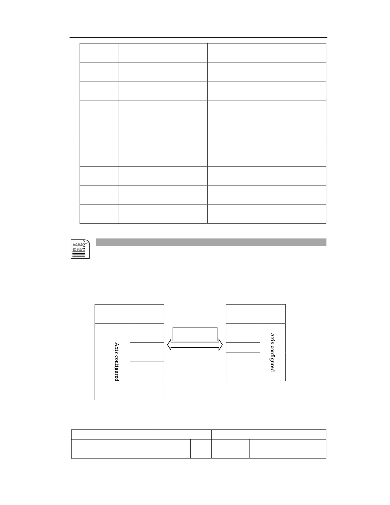
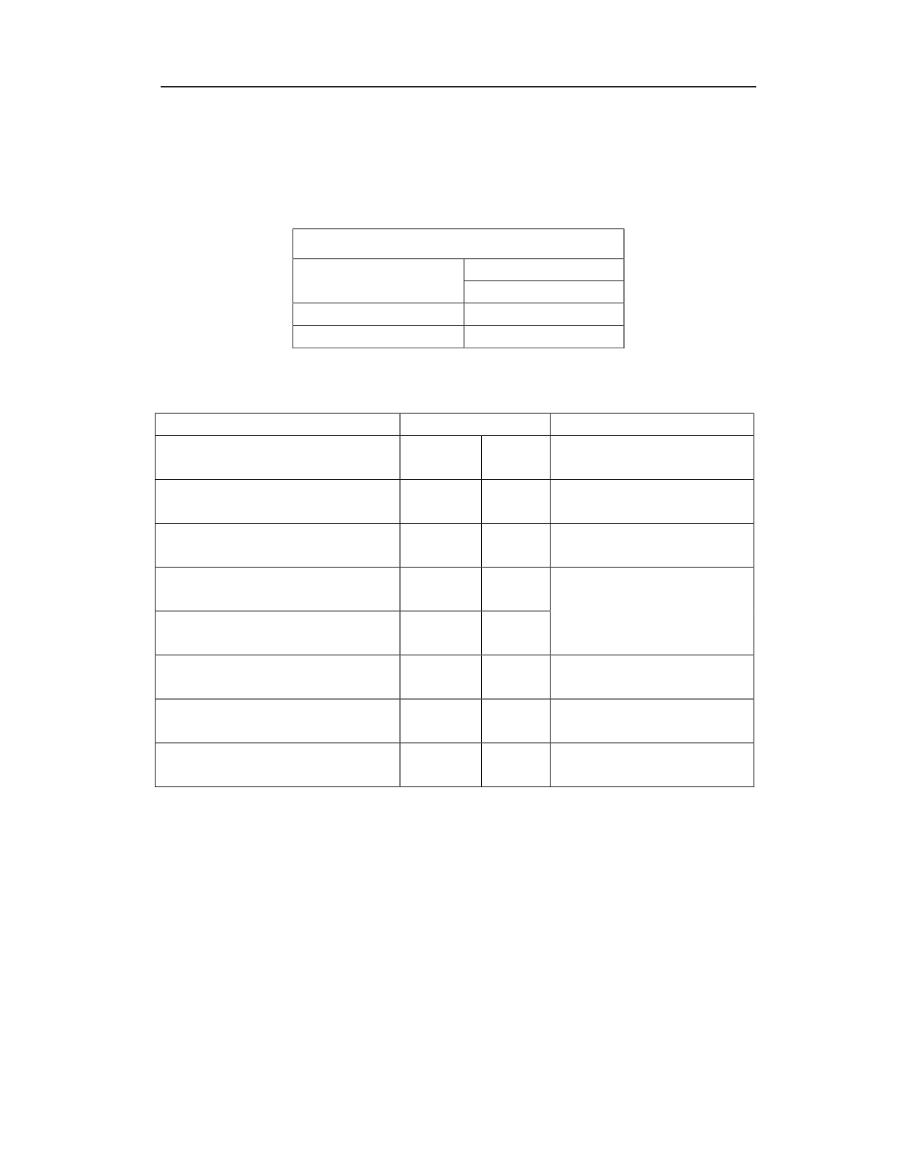
(1) The system is configured with dual channel. The spindles in the two channels need to
synchronously complete the exchange of workpieces (spindle 5 and spindle 6)
Channel 0
Channel 1
X(0)
Synchronous
X(3)
Y(4)
Y(1)
Z(5)
S(6)
Z(2)
S(5)
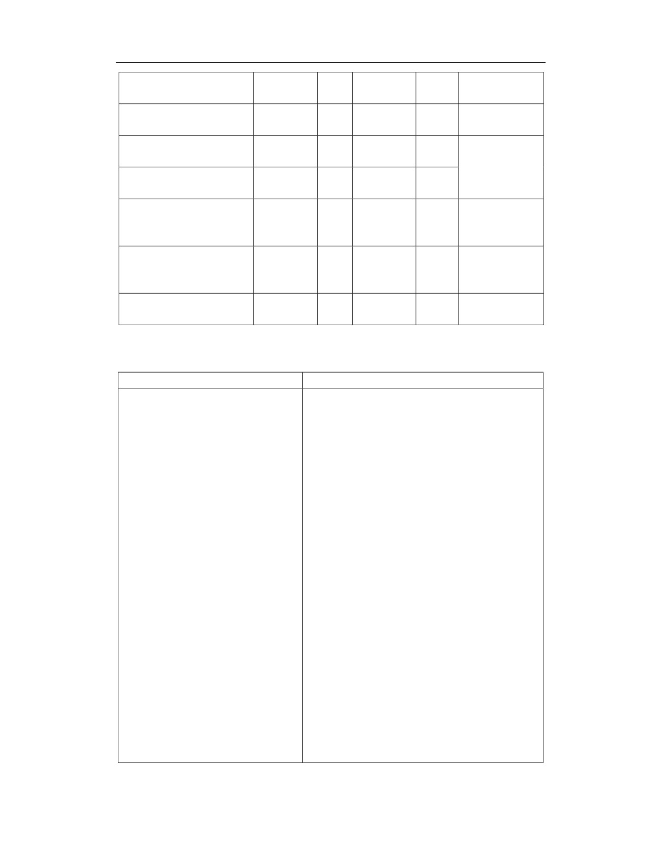
(2) Parameter setting
Channel 0
Channel 1
Parameter
Parameter
Value
Parameter
Value
Explanation
No.
No.
42
The first group of electronic
040340
0
041340
5
Set axis 5 as the
gearbox master axis number
master axis
The first group of electronic
040341
0
041341
6
Set axis 6 as the
gearbox slave axis number
slave axis
The first group of electronic
040342
0
041342
1
Set
the
gearbox master axis ratio
transmission ratio
The first group of electronic
040343
0
041343
-1
of master and
gearbox slave axis ratio
slave axes
The first group of electronic
040344
0
041344
0
Set to the actual
gearbox synchronization type
position
synchronization
The first group of electronic
040345
0
041345
1
Phase
angle
gearbox phase ON
synchronization is
enabled
The first electronic gearbox
040346
0
041346
0
phase angle
(3) Sample program
Channel 0
Channel 1
T0101 G99
G104P1
M3 S1000 ;Master axis starts
M4 S200; Slave axis rotates first (servo needs to be
G4X2
enabled first)
G104P1
G146; Synchronization starts
(The synchronization
G104P2
; Wait for synchronization
to
parameters are based on the settings of above table)
complete
T2222
G0 Y0.0
G98
G99G0 X30.0 Z15.2
G28 Z0.0 X0.0 F5000
G4X0.5
G104P2
G104P3
G104P3
G104P4
M21; Chuck is automatically released
G4 X0.3
G98
G99G1X-2.0F0.06
G0 Z-182.0
M5
;Master and slave axes stop
G1 Z-204 F5000
G104P5
G4 X1.0
G104P6
M22; Chuck is automatically clamped
M30
G4 X0.3
G104P4
G104P5
G28 Z0.0
M5
G104P6
G147; Synchronization ends
M30
43
Example 2
(1) The system is configured with a single channel, one spindle and one power head.
The power head cooperates with the spindle to process 4, 6, and 8 polygons with the fly cutter (the
fly cutter is equipped with 2 tools).
Channel 0
X(0)
Feed axis
Z(2)
Spindle
S(5)
Power head
S1(3)
(2) Parameter setting
Channel 0
Parameter
Parameter
Value
Description
No.
Master axis No. of the first group of
040340
5
Set axis 5 as master axis
electronic gearbox
Slave axis No. of the first group of
040341
3
Set axis 3 as slave axis
electronic gearbox
Master axis ratio of the first group of
040342
0
Not set
electronic gearbox
Slave axis ratio of the first group of
040343
0
electronic gearbox
The first group of electronic gearbox
040344
0
Set to the actual position
synchronization type
synchronization
The first group of electronic gearbox
040345
1
Phase angle synchronization is
phase opens
enabled
The first group of electronic gearbox
040346
0
Not set
phase angle
(3) Sample program:
%1234
M103S1=0; Power head is enabled (slave axis)
M3S200; Master axis starts
G0Z30
G146 I1 J-2 R0; The synchronization is enabled with the transmission ratio of master
and slave axes being 1:-2 (power head rotates reversely); the phase
angle R is 0, at this time a quadrilateral is processed.
T1
G0Z2
44
X-23
G01X-12.44F2
Z0
Z-3F1
G0X-23
M3S200
G146I1J-3R0; The synchronization is enabled with the transmission ratio of master
and slave axes being 1:-2 (power head rotates reversely); the phase
angle R is 0, at this time an hexagon is processed.
G1X-17.6F1
Z-6
G0X-23
M3S200
G146I1J-4R0; The synchronization is enabled with the transmission ratio of master
and slave axes being 1:-2 (power head rotates reversely); the phase
angle R is 0, at this time an octagon is processed.
G1X-20.32F1
Z-9
G0X-23
Z50
X-50
G147; Synchronization ends
M30
Note
1) If I, J, R programming is specified with the G146 command, the corresponding functions set
with the parameters will not take effect. At this time, it is based on the parameter settings in the
program processing command. If I, J, and R are not specified in the G146 command, then the two
spindle coupling control parameters are based on the channel parameter settings.
2) When there is no P parameter in the G146 command, the system uses the first group of electronic
gearbox parameters by default.
3) If the master and slave axes are respectively set in two channels, when using the electronic
gearbox function, the G146 command needs to be executed in the channel to which the slave axis
belongs, and the parameters should also be set in the channel where the slave axis is located.
Otherwise, when running the program in the master axis channel, the system will alarm: the
program syntax error.
4) If G147 is absent in the program, the system will cancel the G146 mode during panel reset or
emergency stop reset. In programming, please note that after enabling G146 synchronization, user
needs to cancel synchronization with G147. Otherwise, when the program runs again, the system
will alarm: the spindle is not ready, and send the command alarm.
45
6 Tool Function
6.1
T Command in Lathe System
Function and Purpose
In the process of machining parts on a lathe, different tools are often used. In order to simplify
the program, it is assumed that the positions of the tool noses are the same during programming.
However, due to the different shapes and installations of the tools, the actual positions of the
noses cannot be consistent. The T command function of the lathe is used to realize the tool
change control and the offset compensation processing for the inconsistency of the actual
positions of the tools.
In addition, when the system realizes position offset compensation, it can also realize tool nose
radius compensation under the same offset number.
Command Format
1. T command function format
T and the following 4 digits, see the figure below.
The first 2 digits are the tool number (the currently selected tool number)
The last 2 digits are the tool compensation number (the register number for storing the
offset and the register number for storing the radius compensation)
Geometry offset number of tool
Tool number selection
2. Relative deviation and absolute deviation
There are two ways to select the commonly used tool deviation: relative deviation and absolute
deviation
Relative deviation value
The position deviation of each tool nose relative to the datum tool nose. In this mode, the
46
program also needs the command to call the position relationship between the datum tool and
the workpiece zero (such as G92 command).
Absolute deviation value
When each tool is at the machine zero position (the machine returns to zero and the tool is at
the machining tool position), the position deviation of the workpiece zero relative to each too
nose. This method is adopted by this system.
Description
1. Tool offset setting
The first two digits of the T command are the tool number for tool selection; the last two digits
are the tool offset number for calling the tool offset. When the tool offset number is 00, it means
that the offset is 0, that is, the offset function is cancelled.
The tool offset number can be the same as or different from the tool number, that is, a tool can
correspond to multiple offset numbers (values).
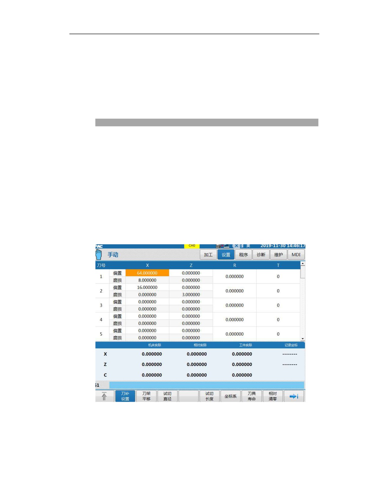
The tool offset is set in the setting interface of the lathe, as shown in the figure below. The tool
offset of the X axis and Z axis can be set through the tool offset setting and tool post translation
setting. For specific operations, please refer to the lathe operation manual.
There is also a wear setting for the wear of the tool. When the tool is worn due to excessive use,
the offset will become larger. When this value is set, the system will also calculate the wear
value on the offset value to correct the tool offset amount (the specific amount of wear is
determined after the workpiece is measured).
The parameter 000064 Tool Wear Accumulation Enable can make the tool wear value set every
47
time be accumulated to the tool offset of the system.
2. Three levels of coordinate system
Machine coordinate system
External zero offset, G54-G59 coordinate systems
T command coordinate system
The low-level coordinate system is completed on the basis of the high-level coordinate system,
that is, the calling of the T command offset and wear is completed on the machine coordinate
system, the external zero offset, and the coordinate system of G54-G59.
Example
External zero offset X is 8, Z is 0
G54 coordinate system X is 4, Z is 0
No. 1 tool offset is X11, wear is 0
No. 2 tool offset is X14, wear is 3
No. 3 tool offset is X9, wear is -1
G54
T0101; Change No. 2 tool No. 2 and call No. 1 tool offset
G01 X5 When the workpiece coordinate system reaches 5, the actual machine X is 28
(5+8+4+11+0)
T0202; Change to No. 2 tool and call No. 2 tool offset
G01 X5 When the workpiece coordinate system reaches 5, the actual machine X is 34
(5+8+4+14+3)
T0303; Change to No. 3 tool and call No. 3 tool offset
G01 X5 When the workpiece coordinate system reaches 5, the actual machine X is 25
(5+8+4+9-1)
T0301; Change to No. 3 tool and call No. 1 tool offset
G01 X5 When the workpiece coordinate system reaches 5, the actual machine X is 28
48
(5+8+4+11+0)
Note
1) Pay attention to the position of the tool when the program executes tool change to prevent
the tool touching other devices.
2) The tool offset value needs to be set for each tool installed.
3) Both the wear value and the offset value will be included in the program. If it is not needed,
0 is set.
4) Regardless of the relative offset or absolute offset mode, the tool offset value generally needs
to be got by tool setting.
6.2
T Command in Milling System
Function and Purpose
The tool function is also called T function, which specifies the tool number. It is designated by
the 4 digits (0~9999) after the address T.
By designating a value following the address T, a code signal is input to the machine tool to
control the tool selection on the machine tool.
When the traverse command and the T command are specified in the same program line, there
are three execution methods based on the M code type:
M06 is to set the synchronization type, and the traverse command and M code are executed
simultaneously;
M06 is set to the Pre type, after the M code is executed, the traverse command is executed
M06 is set to Post type, after the traverse command is executed, the M code is executed
The choice of these three methods depends on the machine tool manufacturer's regulations
Description
When the T command is executed on the machining center, a code signal or pulse signal is input
to the machine tool to control the magazine to rotate to the selected tool, and then wait until the
tool change is automatically completed with M06.
Parameters related to magazine
Machine user parameter 010089 T Command Control Mode sets the tool change mode and
tool processing mode selection of T command in binary.
49
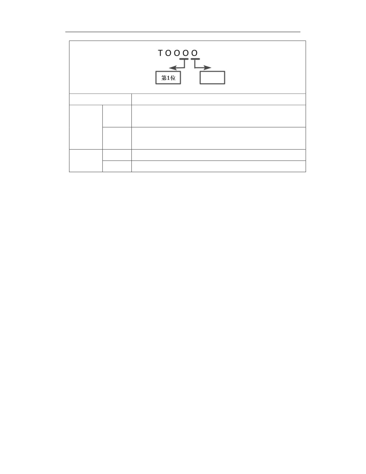
Bit 0
Bit
Functions
T command only has tool selection function for the magazine which have
0
the tool preselection function, e.g., manipulator magazine
Bit 0
T commands have the functions of tool selection and tool change, e.g.
1
magazine of drilling-tapping center
0
Disable tool machining mode
Bit 1
1
Enable tool machining mode
NC parameter 000012 Tool Axis Selection Mode is used to determine which axis the G43/G44
tool length compensation should compensate.
0: Tool length compensation is always compensated to the Z axis.
1: The tool length compensation axis is switched according to the coordinate plane
selection modal G command (G17/G18/G19), corresponding to the Z/Y/X axis respectively.
Channel parameter 040127 Starting Tool Number is used to set the starting tool number of
magazine in the tool compensation table in the current channel, used in conjunction with the
channel parameter Number of Tools
Channel parameter 040128 Number of Tools is used to set the number of tools in the current
channel, which is consistent with the number (or add one) of tool positions of magazine in the
current channel. If the starting tool number in channel 0 is set to 1, the number of tools is set to
5, the starting tool number in channel 1 is set to 6, and the number of tools is set to 10, then the
data saved about the tools 1-5 in the tool compensation table (the tool offset is included for
lathe system) is of the magazine 0 in the channel, and the data saved about the tools 6-15 is of
the magazine 1 in the channel.
The channel parameter 040060 Number of Tool Data Saved by System is used to set how many
tools (radius, length) the system saves. This parameter must be greater than or equal to the sum
of the "number of tools" set in all channels.
Parameter related to big/small tool
Machine user parameter 010099 Magazine Management Interface for Big/Small Tool
0: Disable the magazine management interface for big/small tool;
1: Enable the magazine management interface for big/small tool.
Parameter related to tool grouping and life management
Channel parameter 040130 Tool Life Management Mode
50
0:Disable tool life function;
1:Enable tool life function, and grouping is not supported;
2: Enable tool life function, grouping is supported, and T command specifies tool group
number;
3: Enable tool life function, grouping is supported, and T command specifies tool
number (just for milling system);
Channel parameter 040133 Ignored Number of T Command Life Management.
Channel parameter 040135 Length Compensation of Tool Group in Milling: tool group length
compensation number after tool grouping function is enabled.
Channel parameter 040136 Radius Compensation of Tool Group in Milling: tool group radius
compensation number after tool grouping function is enabled.
Parameters related to multi-tool-edge function
NC parameter 000372 Number of Tool Edges can enable the multi-tool-edge interface. When
the number of tool edges is 0, the regular tool compensation interface is enabled; when the
number of tool edges is 1-9, the multi-tool-edge interface is enabled.
Note
The tools in the magazine table are managed by the system and generally cannot be modified.
For the umbrella type tool magazine, the M06 code and the T command are required to be
written in the same block. Pay attention to the tool magazine table during tool change, the tool
number of group 0 (such as 15) is the position number of the tool clamped on the spindle in
magazine. If other tools need to be installed on the spindle, the tool must be returned to the
position (No. 15) in magazine. At this time, there must be no tools in this position in the
magazine, otherwise a collision will occur.
Therefore, when magazine loads the tool, it is recommended to install the tool on the spindle
first, and then run the M code and T command (such as M06 T01) in the MDI mode to install
the tool in the magazine through the spindle.
51
7 Feed Function
7.1
Overview
Function and Purpose
The feed function is that the CNC system issues a feedrate command to the servo drive, the servo
drive controls the motor, and then controls the movement of the tool or worktable.
The feed function not only needs to specify the speed of the feed movement, but also needs to
plan the speed for the start and stop of the feed movement. The CNC controller adopts automatic
acceleration and deceleration control in the feed control. While the worktable is moving, the speed
and direction of feed may change at the joint between the line segment and the line segment or
between the line segment and the arc, which causes the oscillation of the machine tool, and the
surface quality of the workpiece reduces. Therefore, automatic acceleration and deceleration
control is adopted to avoid this phenomenon.
Description
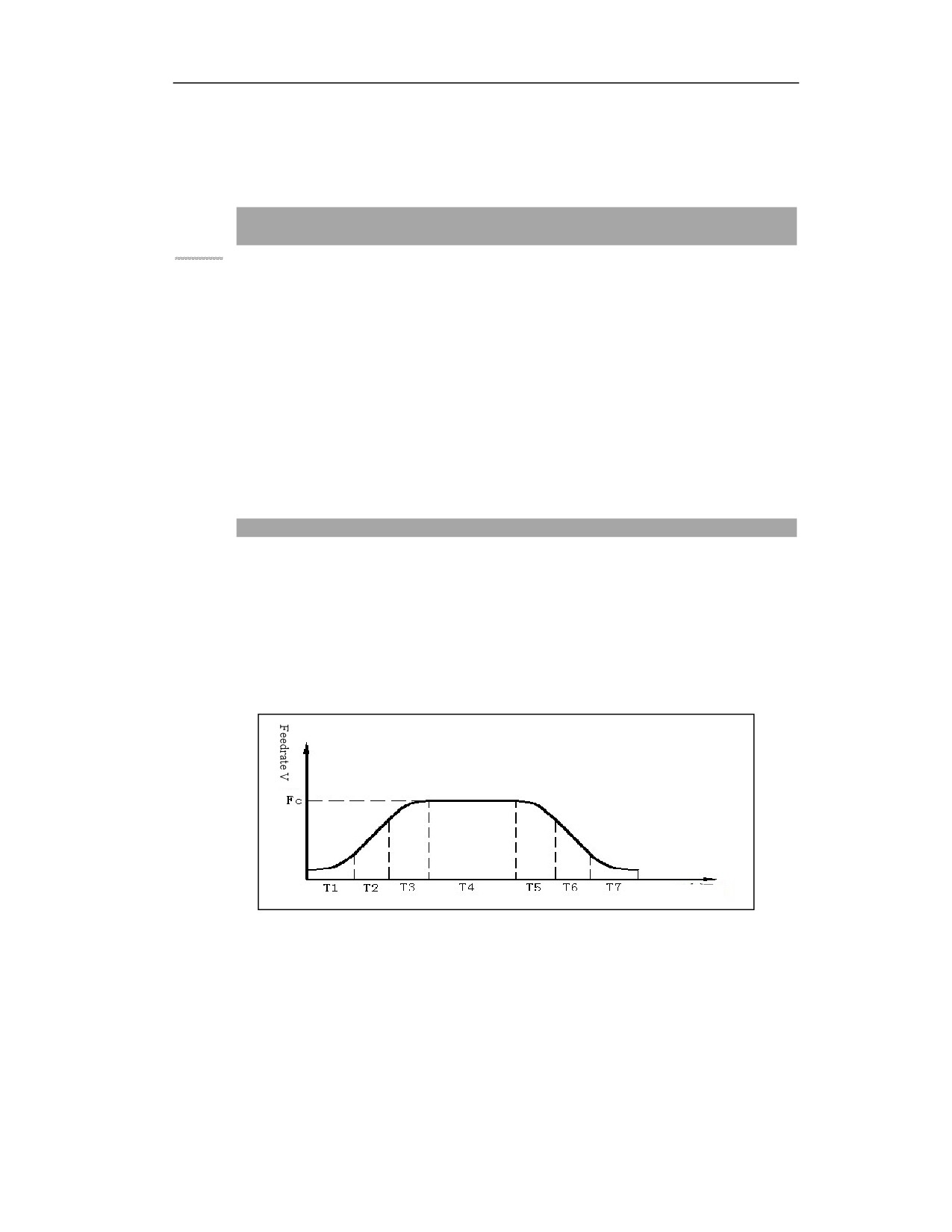
The automatic acceleration and deceleration control of the CNC controller adopts the S-curve
acceleration and deceleration planning method, which accelerates and decelerates during the start
and end of the motion, so that the speed changes softly to adapt to the performance of the motor
and reduce the impact on the machine tool. Real-time control chart. The chart below shows the
real-time control of S-curve acceleration and deceleration
Time t
Through S-curve acceleration and deceleration, the traditional three-stage acceleration and
deceleration is changed into a seven-stage acceleration and deceleration, forming an S curve.
It is divided into: acceleration section composed of T1, T2, and T3; T4 section of the feed at a
constant speed V; deceleration section composed of T5, T6, and T7.
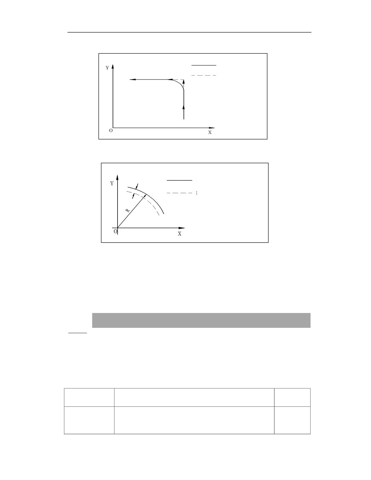
During the cutting, the change of the movement direction between the blocks will cause the
rounded path of tool, as shown in the figure:
52
Actual tool path
Programmed path
Figure A
In the circular interpolation, the radial error appears as shown in the figure:
Error
Actual tool path
Programmed path
Figure B
The fillet trajectory in Figure A and the error shown in Figure B depend on the feedrate. Under
normal circumstances, the greater the speed, the greater the fillet in Figure A, and the greater the
error in Figure B.
Override: Use the knob switch on the machine operation panel to adjust the rapid traverse speed
or cutting feedrate.
7.2
Feedrate Setting
Function and Purpose
According to the specifications of the machine tool, the maximum speed of the machine tool and
the maximum speed of the cutting tool can be set. The maximum speed of the machine tool is the
speed of the machine tool during non-cutting movement, which is mainly determined by the
machine itself. The maximum speed of the cutting of the tool is the maximum speed that the
machine tool can reach during cutting. Their speed can be specified in the following table:
Command mode
Description
Unit
The maximum rapid traverse speed must be the maximum value of
Max. rapid traverse
all the speed setting parameters for the axis. The maximum rapid
mm/min
speed
traverse speed is closely related to the ratio of the external pulse
53

equivalent numerator to denominator. This parameter must be set
reasonably to avoid exceeding the motor speed range.
The maximum cutting feedrate is related to processing
requirements; mechanical transmission is related to the load; the
Max.
cutting
maximum processing speed must be less than the maximum rapid
mm/min
feedrate
traverse speed. The rotary axis is affected by the converted rotation
radius.
The feedrate function has three forms: rapid traverse speed, cutting feedrate, and second feedrate.
7.2.1 Rapid Traverse Speed
Function and Purpose
It is the highest speed for the machine tool, and the rapid traverse speed of each axis can be set
by parameters in the CNC system. The upper limit speed is set based on the condition of the
machine tool. Please refer to the machine tool manual for details.
Description
The Maximum Time for Exact Stop Check (Parm 010166) and Positioning Tolerance (Parm
100060) during rapid traverse.
a) Parm 010166: Set the maximum time for detecting the axis positioning tolerance after rapid
traverse positioning to a certain point. This parameter only takes effect when the axis parameter
Parm 100060 Positioning Tolerance is not 0.
b) Parm 100060: set the allowable exact stop error for the coordinate axis rapid traverse
positioning.
0: The current axis has no positioning tolerance limit.
Greater than 0: When Parm 010166 Maximum Time for Exact Stop Check is reached, if
the current axis machine coordinate still exceeds the set positioning tolerance, the CNC
system will alarm.
The tool moves from the start point to the end point at the highest speed of each axis, and the
rapid traverse speed is valid for G00, G28, and G29 commands.
(Note 1) The rapid traverse federate magnification is set based on the PLC editing and parameter
setting, and generally has two types:
Type 1: Set the 4-stage magnification for 0%, 25%, 50%, and 100%.
Type 2: Set the magnification in 10% units, ranging from 0% to 100%.
54
7.2.2 Cutting Feedrate
Function and Purpose
When the CNC system processes the parts, the cutting feedrate is specified by the address F and
the number. The tool moves at the cutting feedrate programmed. The cutting feedrate is valid for
G01, G02, and G03 commands. There are three command modes for the feedrate unit of the
milling system: G93, G94, G95.
Description
1)Feed per minute
Programming format
G94
; G code of feed per minute (Group 14)
F_
; Feedrate command (mm/min or inch/min)
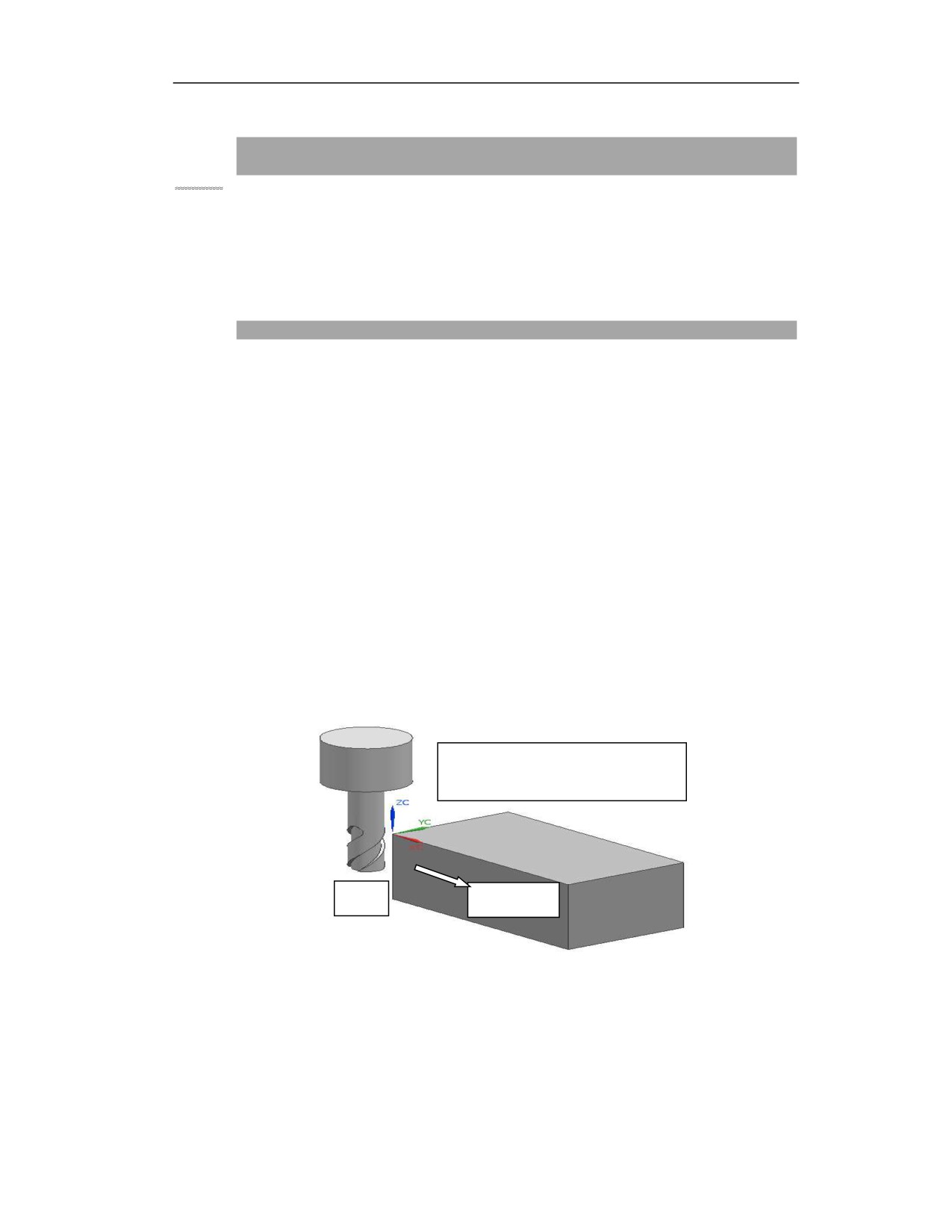
After G94 (feed per minute) is specified, the feed per minute of the tool is directly specified by
the value after F. G94 is a modal code. Once G94 is specified, it will remain valid until G95 (feed
per revolution) is specified. When the power is turned on, the default setting is feed per minute.
The switch on the machine operation panel can be used to to set the magnification for the feed
per minute, and the magnification can be set from 0% to 150% (the override interval is determined
by the MCP panel of the system). When G94 is specified, the feedrate F of the movement
command specifies the movement amount of the tool per minute, with the unit mm/min (G21
mode) or inch/min (G20 mode).
Feed amount per minute(mm/min,
inch/min)
Tool
Workpiece
Example: feed per minute
G01 X-20 Y-10 F300
;Feedrate 300mm/min
55
2)Feed per revolution
Programming format
G95
;G code of feed per revolution (Group 14)
F_
;Feedrate command (mm/rev or inch/rev)
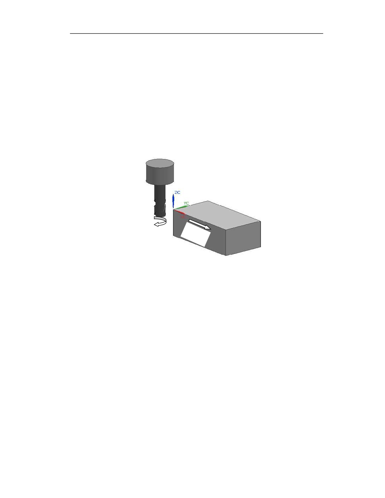
After G95 (feed per revolution) is specified, the value after F directly specifies the tool feed per
revolution (G95) of the spindle. G95 is a modal code. Once G95 is specified, it will remain valid
until G94 (feed per minute) is specified. With the switch on the machine operation panel, the
federate override can be applied to the feed per revolution, and the magnification ranges from 0%
to 150%.
Spindle rotation S
Feed F
Example:G95
M03 S1000
G01 X-50 Y-20 F0.2
; feedrate per revolution is 0.2mm/rev
Correspondence between feed per revolution and feed per minute: when spindle speed and feed
per revolution F are given, for example spindle speed S1000 and feed F0.2.
Feed per minute(F)=1000(spindle speed)×0.2(feed per revolution)=200mm/min
3)Inverse time feed
Command format
G93
;Inverse time feed command (Group 14)
F_
;Feedrate command(l/min)
By specifying G93, it becomes the inverse time specification mode. The inverse time feed
function is realized by the reciprocal of the specified speed, that is, the time it takes to execute the
current block. Use the F code to specify the inverse time FRN. The specified range of FRN is not
restricted by the inch/metric input, and the range is from 0.001 to 9999.999.
56
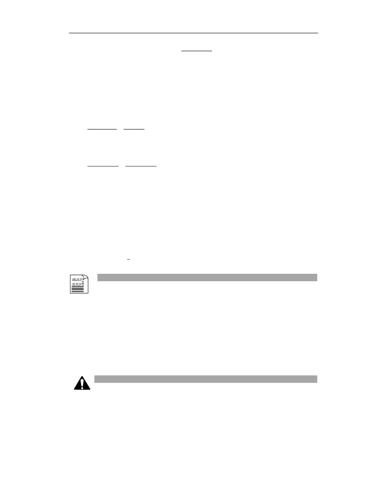
ଵ
FRN=
= ୗ୮ୣୣୢ
୧୫ୣ(୫୧୬)
ୈ୧ୱ୲ୟ୬ୡୣ
Speed: mm/min (in metric) or inch/min (inch)
Distance: mm (in metric) or inch (in inch)
When linear interpolation (G01) and circular interpolation (G02, G03)
(1)If one program line is ended in 1 minute,
FRN =ଵ
= ଵ
=1
;F1 is specified in program.
୧୫ୣ(୫୧୬)
ଵ(୫୧୬)
(2)If one program line is ended in 20 seconds,
ଵ
ଵ
FRN =
=3
;F3 is specified in program.
୧୫ୣ (ୱୣୡ)/ =ଶ/(୫୧୬)
(3)When the traverse time for F0.5 is specified, the time needed for execution of one program
line is,
Time(min)= ଵ
=ଵ
= 2
;2 minutes are needed.
ୖ
.ହ
(4)When the traverse time for F5 is specified, the time needed for execution of one program
line is,
Time(sec)= ଵ
=ଵ= 0.2
;12 seconds are needed.
ୖ
ହ
Example
G01 X10
G93
G01 X20 F10
;X axis moves 10mm after 0.1 minute (6 second)
The correspondence between the inverse time feed and the feed per minute: when the inverse time
feed F is given, for example F10. In the formular FRN=0.1(min)=6(sec), then it takes 6 seconds
to move the X axis 10mm. the feed rate per minute (F)=10/0.1=100mm/min.
Note
1) G93, G94, G95 are in the same group (Group 14). They are modal G codes, and mutually
cancelable. G94 is the default modal.
2) When F is designated in G93 mode and the calculated speed exceeds the maximum cutting
speed, the actual speed is clamped to the maximum cutting feed rate.
3) When circular interpolation is used in G93 mode, the speed is calculated from the arc radius,
57
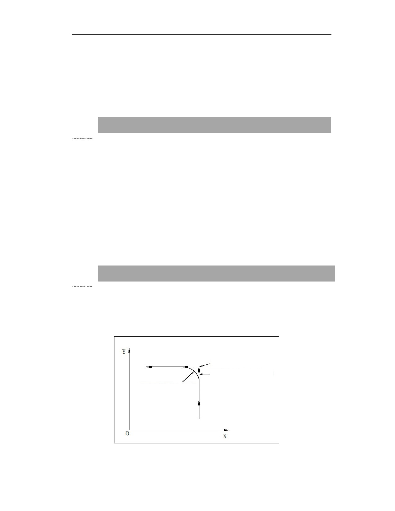
not from the actual moving distance of the program line. Therefore, when the arc radius is longer
than the arc distance, the actual time slows down; and when the arc radius is shorter than the arc
distance, the actual time speeds up. The cutting feed in a canned cycle can also use inverse time
feed.
4) The G93 command inverse time feed mode should be specified separately.
7.2.3 2nd Feedrate
Function and Purpose
The second feedrate E, which is different from the feedrate F, is generally used to limit the feedrate
at the end of the block. For example, in NURBS curve interpolation, F command specifies the
feedrate during interpolation, and E specifies the feedrate at the end of interpolation.
The feedrate F is a modal command, and the second feedrate E is a non-modal command, and it
is used when the second feedrate is required. If E is not specified, 0 is the default.
The second feedrate is mainly used in more complicated interpolation control, and is currently
only used in NURBS curve interpolation (G06.3).
(Note 1) The feedrate override has been configured in parameters 010308 to 010328, and ranges
from 0% to 120%.
7.3
Feed Control Mode
Function and Purpose
During cutting and feed, the trajectory of the tool is different in different control modes. There are
two cutting feed control modes for the CNC controller: exact stop and continuous cutting. For parts
needing sharp edges and corners, exact stop control is used; while parts with fillet edge or small
line segment programs, the continuous cutting is used.
Positioning tolerance check
Tool path in exact stop
mode
Tool path in cutting
mode
The correspondence between the two control modes is as follows:
58

Group
Cutting mode
G code
Modal
Description
No.
The tool decelerates at the end of the block
G09
Non-modal
00
and the positioning tolerance check is
Exact stop
performed. Then the next block is executed.
G61
Modal
The tool decelerates at the end of the block
and the positioning tolerance check is
12
performed. Then the next block is executed.
G64
Modal
The tool executes the next block without
Continuous cutting
(G05.1 Q0)
deceleration at the end of the block.
Description
1) Exact stop control
Non-modal exact stop G09
G09 is a non-modal command, which is only valid in the block where the G09 is specified.
Modal exact stop G61
G61 is a modal command (group 12). Once it is specified, the function remains valid until G64 is
specified.
2) Continuous cutting control G64
(1) G64 is a modal command (group 12). Once it is specified, this function is valid until G61 is
specified.
(2) For continuous cutting, whether to perform exact stop check at the corner between line segments
can be set by parameter G64 Parm 010169 (enable exact stop check at corner).
(3) The G64 is to set whether the exact stop at corner with G64 is performed. When this parameter
is set to 1, the CNC system will enable the exact stop check at corner with modal G64.
(4) In modal G64, if the feed length of the two adjacent straight lines is less than or equal to 5mm
and the vector angle is less than or equal to 36°, the CNC system will automatically adopt the arc
transition, which is not controlled by this parameter.
59
Example
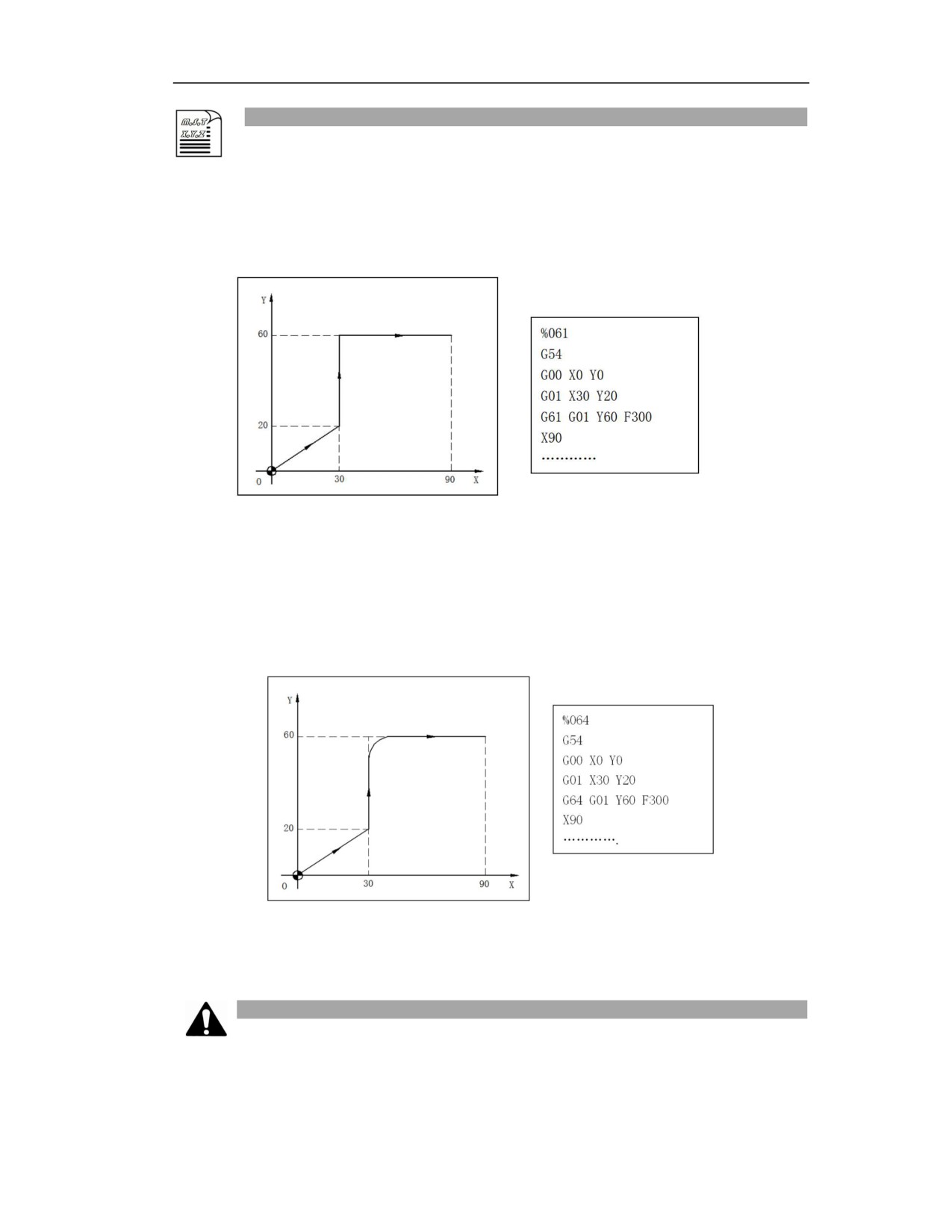
Example 1
Programming for the contour as shown in the figure: The programmed contour is required to match
the actual contour.
The programmed contour with G61 is the same as the actual contour.
Example 2
Programming for the contour as shown in the figure: Not stop is required between the blocks.
The programmed contour with G64 is different from the actual contour, and there is arc connecting
between the line segments.
Note
1) The difference between G61 and G09 is that G61 is a modal command, while G09 is a non-
modal command.
60
2) The programming axes in each block after G61 must stop exactly at the end of the block, and
then the next block is continued to be executed. The programmed contour with G61 and G09
conforms to the actual contour.
3) G64 (G05.1 Q0) continuous cutting mode:
When the programmed axes after G64(G05.1 Q0)just start to decelerate (the programmed end
point is not reached), the next block is executed. However, in the blocks with positioning commands
(G00, G60) or with exact stop check (G09), and in blocks without motion commands, the
positioning check is performed after the feedrate is decelerated to 0.
4) G61 and G64 (G05.1 Q0) are modal commands, which can be mutually cancelled.
5) The programmed contour with G64 (G05.1 Q0) is different from the actual contour. The
difference depends on the F value and the angle between the two paths. The greater the F, the greater
the difference.
7.4
Feedrate Control
Function and Purpose
When the CNC system is running the program in speed control, the tool needs to automatically
decelerate when performing circular processing and corner processing to reduce the load on the
tool, thereby reducing the impact on the machine tool, and avoiding tool marks on the workpiece.
Description
Circular speed control
(1) For circular cutting, the feedrate on the programmed path is controlled by the circular
deceleration radius (Parm 040042) and the circular deceleration speed (Parm 040043).
a) Circular deceleration radius (Parm 040042): to set the maximum circular radius for
deceleration. When the programmed circular radius is less than the set value, the feed cutting
is executed at the set circular deceleration speed (040043). When the programmed circular
radius is greater than the setting, the deceleration control is not performed. When 0 is set,
the circular deceleration function is invalid.
b) Circular deceleration speed control (Parm 040043): to set the target speed for circular
deceleration. When the programmed circular radius is smaller than the circular deceleration
radius (040042), the feed cutting is executed based on the set value. When the programmed
circular radius is greater than the circular deceleration radius (040043), the deceleration
control is not performed. When 0 is set, the circular deceleration function is invalid.
(2) For the large circular radius, the speed control can be directly performed by circular
61
interpolation, or can be performed by Parm 040149 (Whether Arc is Discrete into Straight Line).
Parm 040149 Whether Arc is Discretized into Straight Line: when the arc can be discrete into
straight line, the arc can be discretized into the connection of tiny line segments. Then for the case
where the straight line meets the arc or the arc meets the arc, it can be equivalent to the straight line
meets the straight line, and the speed at the junction of the two can be processed in the mode of
deceleration at corner.
0: Turn off the function of arc discrete into straight line.
1: Turn on the function of arc discrete to straight line.
(3) When performing radius compensation, the automatic deceleration mode adopted for circular
feedrate control is to use the parameter Parm 010044 Radius Compensation Circular Speed Strategy.
Radius compensation circular speed strategy Parm 010044: This parameter is used to adjust the
circular speed after radius compensation.
0: Turn off the function
1: Speed after radius compensation = (circular radius after radius compensation /
circular radius before radius compensation) * programmed speed
2: Speed after radius compensation
= sqrt
(circular radius after radius
compensation/circular radius before radius compensation) * programmed speed
11 to 19: Speed after radius compensation = programmed speed* (0.1 to 0.9)
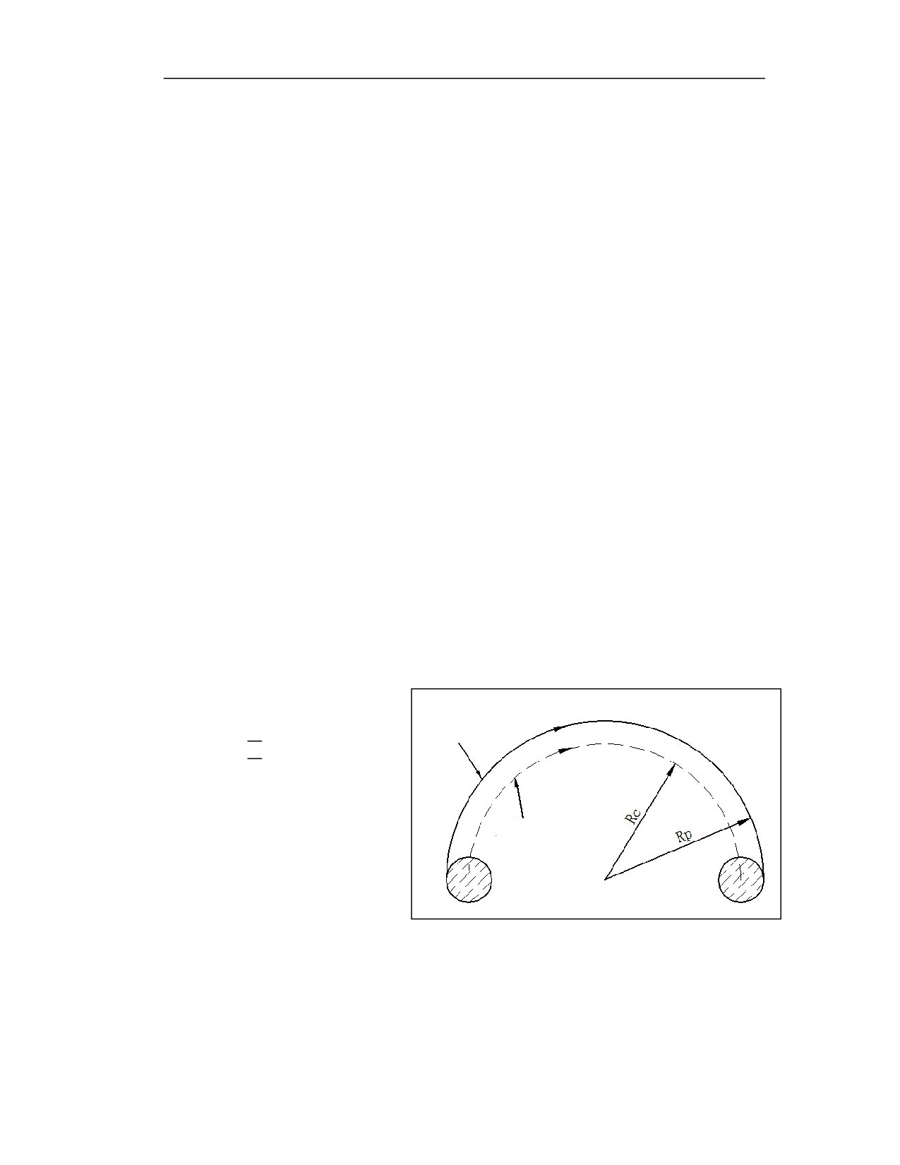
(Note 1) Modes 1 and 2 are the feedrate for the programmed path, which is determined by the
programmed value F of the circular cutting feedrate and the circular radius, as shown in the figure.
In the tool radius compensation mode, this function is valid.
1:F×ୖୡ
ୖ୮
Programmed path
2:F×ටୖୡ
ୖ୮
Rc: Tool center path radius
Tool center path
Rp: Programmed radius
62
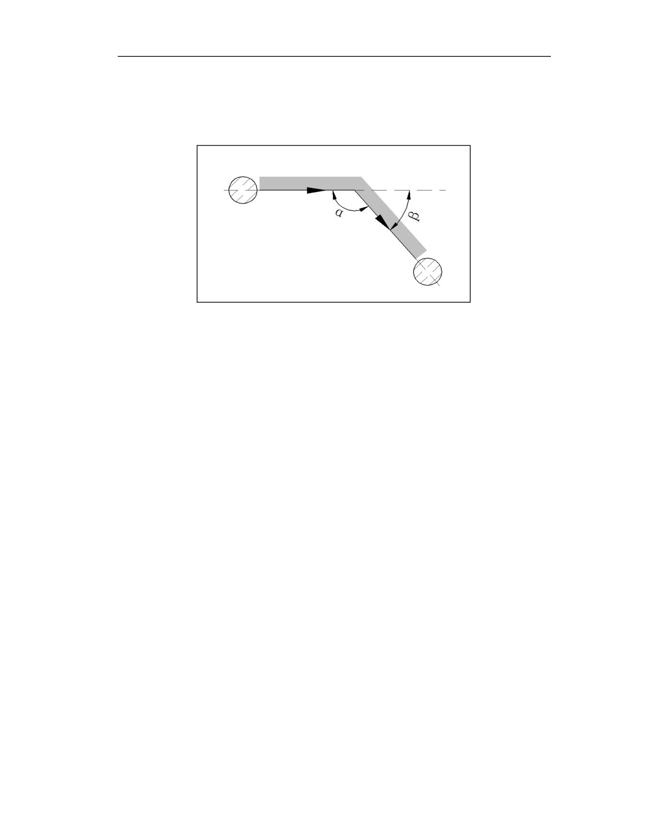
Corner speed control
When the CNC system is running the program, it uses the method shown in the figure to determine
whether it is a corner or a straight line (or basically a straight line) between the program blocks.
In the figure, α is the minimum internal angle (degree) of the corner to determine whether it is a
corner of the connection between the line segment amnd the line segment, and the β angle is to
determine whether it is a straight line or basically a straight line.
(1) Parameter related to the corner (α angle):
a) Parm 040141 Minimum internal angle for corner smoothing: During continuous small
line segment interpolation, local speed reduction can be performed based on the actual
programmed trajectory. When the sharp corner of the contour needs to be highlighted, the
speed should be reduced to zero at the top of the sharp corner. This parameter is used to set
the value of this angle. If the processed angle is less than this angle, the exact stop will be
performed; if it is greater than this angle, other ways will be used to plan the speed reduction
processing at this angle. If the maximum directed angle is set to 45°between the two small
line segments which are allowed to be compressed and merged, this parameter should be set
to 45.
b) Parm 040144 Deceleration scale factor at corner: For the polyline segment whose corner
angle is greater than the minimum smoothing internal angle (040141), the feed is executed
at the corner with circular transition, and the deceleration scale factor at corner can be used
to control the deceleration speed at corner. The smaller the set value, the smaller the
deceleration speed at corner, the smaller the corner roundnes, and the contour accuracy is
theoretically higher; but the milling time at the corner becomes longer and the efficiency is
reduced.
(2) Parameter related to collinear determination (β angle)
a) Maximum angle threshold in collinear determination: This parameter sets the maximum
exterior angle between two adjacent line segments which are determined to be collinear.
When the exterior angle is less than this value (radian value), the two line segments are
collinear, otherwise they are not. 0.017 is the default value.
63
(3) For the length and deviation of the small line segment spline fitting, the upper limit length of
the small line segment (mm) (Parm 040140), the lower limit length of the small line segment (mm)
(Parm 040145), and the allowable contour error of the small line segment trajectory (Parm 040143) )
are used for the spline fitting processing of the CNC system.
a) The upper limit length of the small line segment
(mm) (Parm 040140): used in
conjunction with the lower limit length of the small line segment to form the area range for
the small line segment spline fitting.
b) Allowable contour error of small line segment trajectory
(Parm 040143): During
continuous small line segment interpolation, the small line segment can be compressed and
merged based on the actual programmed trajectory. This parameter is to set the allowable
contour error between the compressed and merged small line segment and the original
programmed trajectory. When the contour error exceeds the set value, it will not be
compressed.
c) The lower limit length of small line segment (mm) (Parm 040145): During spline
interpolation, the spline smoothing (fitting) needs to be performed on the small line segment
based on the actual programmed trajectory. This parameter is to set the shortest length of
small line segment where the smoothing is allowed. If the length of the small line segment
is less than the set value, the smoothing of this line segment is not performed.
64
8 Position Command Function
8.1
Mode I of Absolute Command and Incremental Command(G90/G91)
Function and Purpose
There are two modes to define the position of the target point: absolute position and incremental
position.
For easier programming, the definition of the position should fit the workpiece drawing. When a
fixed reference point is given in the drawing, it is more convenient to use absolute programming;
and when the drawing size is given by the spacing between the contour nodes, it is more
convenient to use incremental programming.
There are two modes of absolute command and incremental command in the CNC system: mode
I and mode II. The mode 1 can be executed in lathe ystem (T) and milling system (M), and the
mode II can only be executed in lathe system (T).
Command Format
Mode I of absolute command and incremental command.
G90 IP_ Absolute programming
Parameter
Meaning
IP
By absolute command G90, the traverse command is always executed
with the workpiece coordinate system as the starting point
G91 IP_ Incremental programming
Parameter
Meaning
IP
By incremental command G91, the traverse command is always executed
with the current point as the starting point
Description
Absolute command G90: define the address of the target point. The value after the address word
is the coordinate value in the workpiece coordinate system;
Incremental command G91: define the address of the target point. The value after the address
word is the directional distance value from the target point to the previous point;
When using G90, G91 commands, the coordinate movement values after the commands can be
specified in absolute mode or incremental mode, but when defining the circular trajectory, the
radius R and circle center I, J, K values must be incremental values. G90 and G91 are modal
65
commands and can be mutually cancelled. G90 is the default.
Example
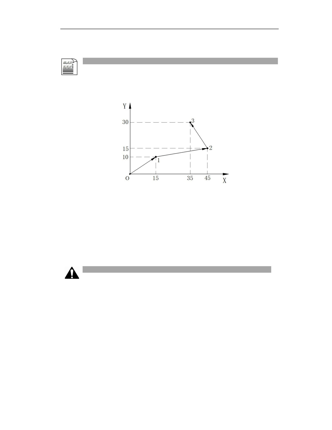
Example 1: The origin is the starting point, programming with G90 and G91; the tool is required
to move from the origin to points 1, 2, and 3 in order.
Starting
point
G90 programming
G91 programming
%
%
G54
G54
G00 X0 Y0 M3 S1000
G00 X0 Y0 M3 S1000
G90 G01 X15 Y10 F400
G91 G01 X15 Y10 F400
X45 Y15
X30 Y5
X35 Y30
X-10 Y15
M30
M30
Note
1) When using the G90 command to run the program, the system is in the absolute mode. During
running of the traverse command, the workpiece coordinate system is always used as the starting
point to move to the workpiece coordinate system position specified by the program, regardless
of the current position.
2) When using the G91 command to run the program, the system is in the incremental mode.
During running of the traverse command, the current position is always the starting point and the
value specified in the program is used as a relative value for moving.
3) G90 and G91 can be used in the same block, but pay attention to the difference caused by their
order.
4) The mode 1 of absolute command and incremental command can be executed in both lathe
system and milling system.
66
8.2
Mode II of Absolute Command and Incremental Command(X, Z/U, W(T)
Function and Purpose
There are two modes of absolute command and incremental command in the CNC system: mode
I and mode II. The mode 1 can be executed in lathe ystem (T) and milling system (M), and the
mode II can only be executed in lathe system (T).
When using mode II for programming, the switching between absolute position and incremental
position is simple. It is especially suitable for mixed programming, but it occupies the axis name
definition of the auxiliary axis, so this mode is more suitable for lathe system.
Command Format
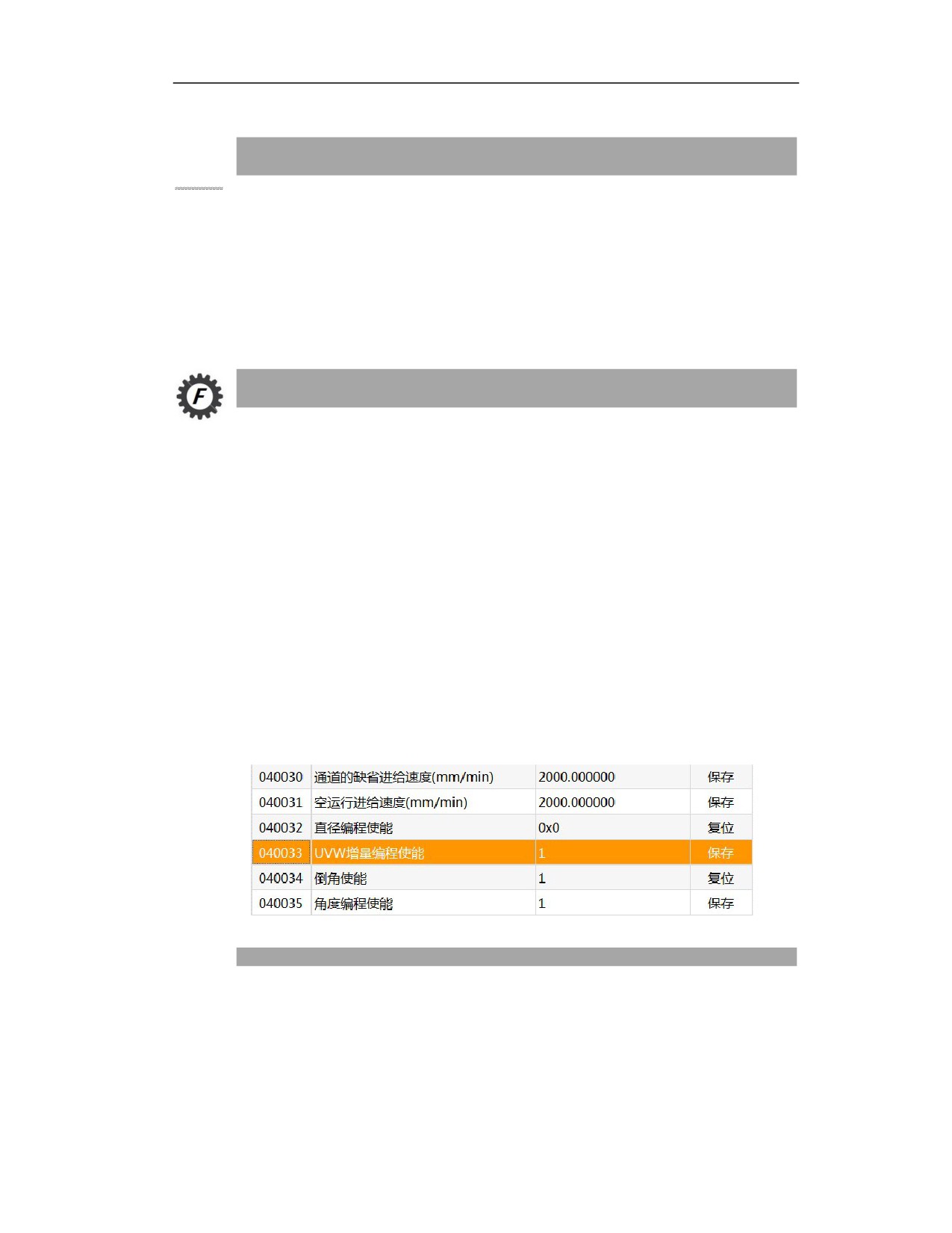
If user needs to use the mode II of absolute command and incremental command in lathe syste, it
is necessary to configure the parameter 040033 [UVW incremental programming enable] in the
channel parameter.
When the parameter 040033 is specified as 1, the incremental value programming can use U, V,
W to represent the incremental values on X, Y, Z axis respectively. At this time, the absolute value
is still specified by X, Y, and Z with G90. G90 is the default and does not need to be defined. The
format of mode II is: U, V, and W are for incremental programming, and X, Y, and Z are for
absolute programming. Of course, it can also be executed if the mode I is used for programming
at this time.
When parameter 040033 is specified as 0, the mode I is enabled. At this time, U, V, W definition
for incremental position cannot be executed.
The definition of channel parameter 040033 is shown in the figure below:
Description
1. Linear incremental programming
G01 X10 Z5 Move to 10 on X of the workpiece coordinate, and 5 on Z of the workpiece
coordinate;
G01 U10 W10 Move in the positive direction 10 on X based on the current coordinates, and
67
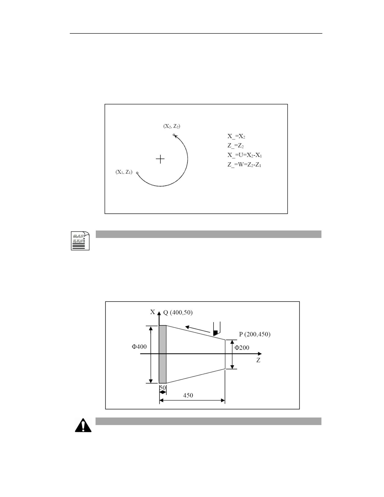
move in the positive direction 10 on Z based on the current coordinates.
2. Circular incremental programming
For circular programming, in addition to specifying the end position by absolute programming,
incremental programming can also be used to specify the incremental value in each direction of
the arc (UVW is also used), and it can also use XYZ and UVW for mixed programming.
End point
End point of arc
Absolute:
Incremental:
Starting point
Example
Tool moves to Q from P (The diameter value is on X axis)
Absolute command:G90X400Z50
Incremental command:1. G91X200Z-400
2. U200W-400
Note
1)UVW programming is only used for lathe system.
68
2)G91 is a modal command, and cannot be canceled by itself. The lines after G91 are all in G91
programming, and its modal can be canceled by G90.
8.3
Diameter Programming and Radius Programming(G36/G37
(T)
Function and Purpose
The workpiece on a CNC lathe is usually has a shape of rotating body, and its size on X axis can
be specified both by diameter mode and radius mode.
Radius programming: Use the radius value to define the X axis position of the target point. There
are two types: absolute radius value and incremental radius value. The absolute radius value is
the radius coordinate value on X axis; the incremental radius value is the incremental radius value
on X axis.
Diameter programming: Use the diameter value to define the X-axis position of the target point.
There are also two types: absolute diameter value and incremental diameter value. The absolute
diameter value is the diameter coordinate value on X axis; the incremental diameter value is the
incremental diameter value on X axis.
Diameter programming is more in line with the drawing of parts, so the diameter programming is
the default for lathe machine. The value in diameter programming is twice the value in radius
programming.
The setting of diameter programming is often used on the X axis of the lathe, and other axes
perpendicular to the rotary axis can also be set as the diameter programming axis when needed,
such as the Y axis of some turning centers.
Command Format
G36;
Diameter programming
G37;
Radius programming
G36 and G37 can be used to switch between diameter and radius programming.
Description
When the channel parameter 040032 is set to 0X1, the X-axis diameter programming of the
machine tool is enabled, and G36 or G37 can be used to set the diameter programming or radius
programming.
69
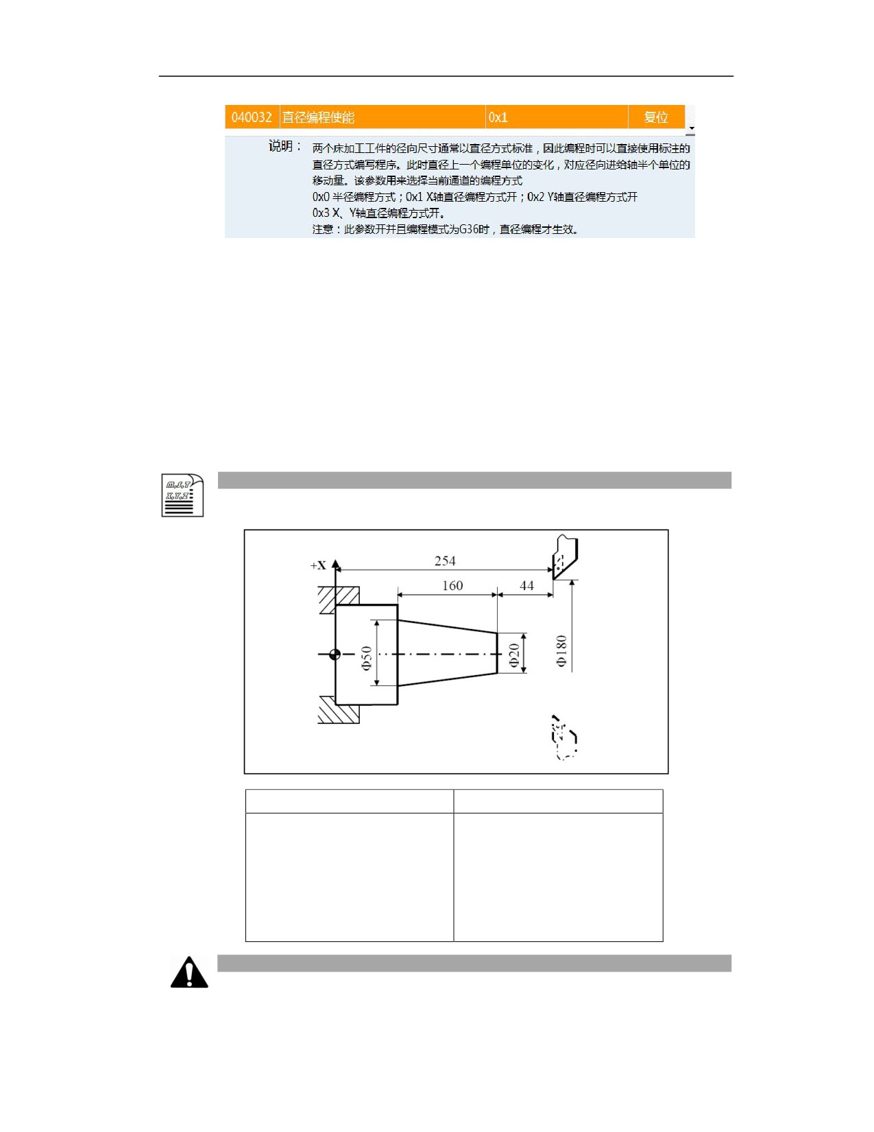
After the diameter programming is enabled, the default is G36 command (diameter programming).
After switching to radius programming with G37, it is necessary to return to diameter
programming with G36.
When using diameter programming, it is recommended to turn on the diameter display enable.
NC parameter 000065 is the parameter of Diameter Display Enable. For example, when the
parameter is set to 0X1, the X axis diameter display is enabled, and the X position value on the
system display interface is in diameter. The tool offset and the offset and wear on the tool
compensation interface are also displayed in diameter.
Example
Diameter programming
Radius programming
%3341
%3342
N1 G92 X180 Z254
N1 G92 X90 Z254
N2 G36 G01 X20 W-44
N2 G37 G01 X10 W-44
N3 U30 Z50
N3 U15 Z50
N4 G00 X180 Z254
N4 G00 X90 Z254
N5 M30
N5 M30
Note
1) Z axis command input has nothing to do with diameter and radius programming;
70
2) When G02 and G03 are specified, the R, I and K are the radius values;
3) R, the feed amount on X axis used in a symple canned cycle, is specified in radius;
4) For the lathe and turning center systems, the default is G36 diameter programming;
5) The axial feedrate is specified by the change of radius.
8.3
Inch/Metric(G20/G21)
Function and Purpose
User can select the unit of size through G20, G21.
Command Format
G20 IP_ Inch
Parameter
Meaning
IP
After G20 is specified, the traverse distance after
G20 is in inch.
G21 IP_ Metric
Parameter
Meaning
IP
After G21 is specified, the traverse distance
after G21 is in metric.
Description
Only the command unit can be switched with G20/G21, but not the input unit.
G20/G21 only works on the linear axis, and is invalid to the rotary axis.
Note
1) G20 and G21 are modal commands and can be mutually cancelled. The default is G21 after the
system is powered on.
2) The unit of data input in the G code is not related to the unit of data displayed on the HMI
interface. G20 and G21 are only used to select the unit of data input in processing G codes, and
cannot change the data unit displayed on the HMI interface.
71
3) Parameter 000025 [Inch/Metric] in NC parameters is used to set the data unit of the coordinate
displayed on the interface.
72
9 Delay Function
9.1
Delay Function
Function and Purpose
This function can suspend the movement of the machine tool by G04 X_ or P_ command to delay
the start of the next program. The delay time unit is X for seconds and P for milliseconds.
Command Format
G04 X__ / P__
Parameter
Meaning
X/P
Dwell time
X
Unit: second
P
Unit: millisecond
Example
Command
G04 X5
G04 X2.5
G04 P2000
G04 P1000.5
Delay seconds
5
2.5
2
1
Description
1) When the delay time is specified by X, the decimal point command is valid.
2) When the delay time is specified by P, the commands after the decimal point are ignored.
3) If there is a cutting command in the previous block, the delay time will be started to be
calculated after the block is stopped.
4) When the machine tool is locked, the delay command is also valid.
5) During the automatic operation, user can specify G04 to suspend the tool feed, and the
subsequent blocks will be executed automatically after the dwell time is reached.
6) The command value range of the dwell time: X minimum value is 0, maximum value 2000; P
minimum value is 0, maximum value 2147400.
73
Note
1) When using this function, please issue the X or P command after the G04 command to make it
clear that X or P is executed.
2) The number followed by X cannot exceed 2000, otherwise the system will alarm "Syntax-
Illegal number".
74
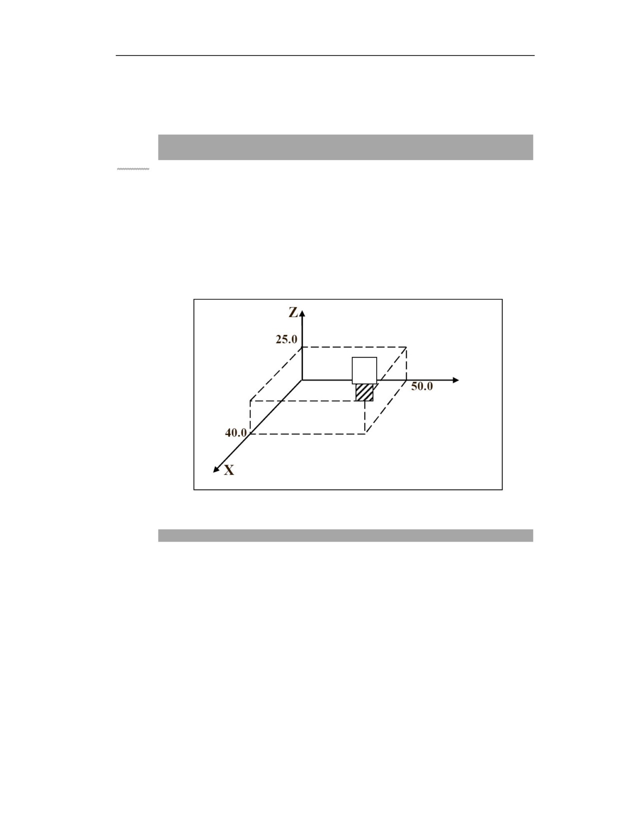
10 Coordinate System
10.1
Overview
Function and Purpose
In processing of machine tool, when a position reached by the tool is preset, the tool can move to
the specified position. This position should be given by the coordinate value in a certain
coordinate system, and the coordinate value is specified by the programmed axis. In this way, the
required workpiece can be processed based on the program.
When the 3 programmed axes are X, Y and Z axes, the coordinate values are specified as follows:
X_Y_Z_: This command is called size word.
The tool position specified by X40.0Y50.0Z25.0
Description
The system supports the following three coordinate systems for user to choose: (1) machine
coordinate system; (2) workpiece coordinate system; (3) local coordinate system.
The machine coordinate system is the fixed coordinate system of the machine tool, which
represents the position inherently determined by the machine tool.
The workpiece coordinate system is the coordinate system used by the programmer during
programming, and generally the reference point on the workpiece is regarded as the coordinate
origin.
The local coordinate system is a coordinate system created on the workpiece coordinate system
in order to simplify the creation of part of the processing program.
75
Note
The local coordinate system (G52) is valid in the coordinate system specified by workpiece
coordinate systems 1 to 6.
10.2
Machine Coordinate System
76

Function and Purpose
The machine zero is a fixed mechanical point on the machine tool. The coordinate system
established by the machine tool manufacturer with this point as the origin is referred to as the
machine tool coordinate system.
After turning on the power, manual reference point return is executed to establish the machine
coordinate system. Once the mechanical coordinate system is established, it remains unchanged
until the power is cut off.
Command Format
G53 X__/ Y__/ Z__/; Absolute size (target position in machine coordinate system)
Description
1) G53 is a non-modal command, which is only valid in the block where the machine coordinate
system is specified. When user needs to execute direct machine tool coordinate system
programming, G53 must be specified in the current line;
2) The target position specified by G53 cannot be in incremental programming, only absolute
programming can be used. When the incremental command (G91) is specified, the G53 command
is ignored.
3) When G53 command is specified, the tool radius compensation, tool length compensation, tool
nose radius compensation and other functions are cleared.
4) Before specifying the G53 command, the machine coordinate system must be set. Therefore,
the reference point must be returned manually or automatically by the G28 command after power-
on. When an absolute encoder is used, this operation is unnecessary.
5) Machine coordinate system is set before calling G53. The system must establish the machine
coordinate system through the reference point return.
6) The system reference point does not necessarily coincide with the origin of the machine
coordinate system, and the relationship between them is shown in the figure below.
77
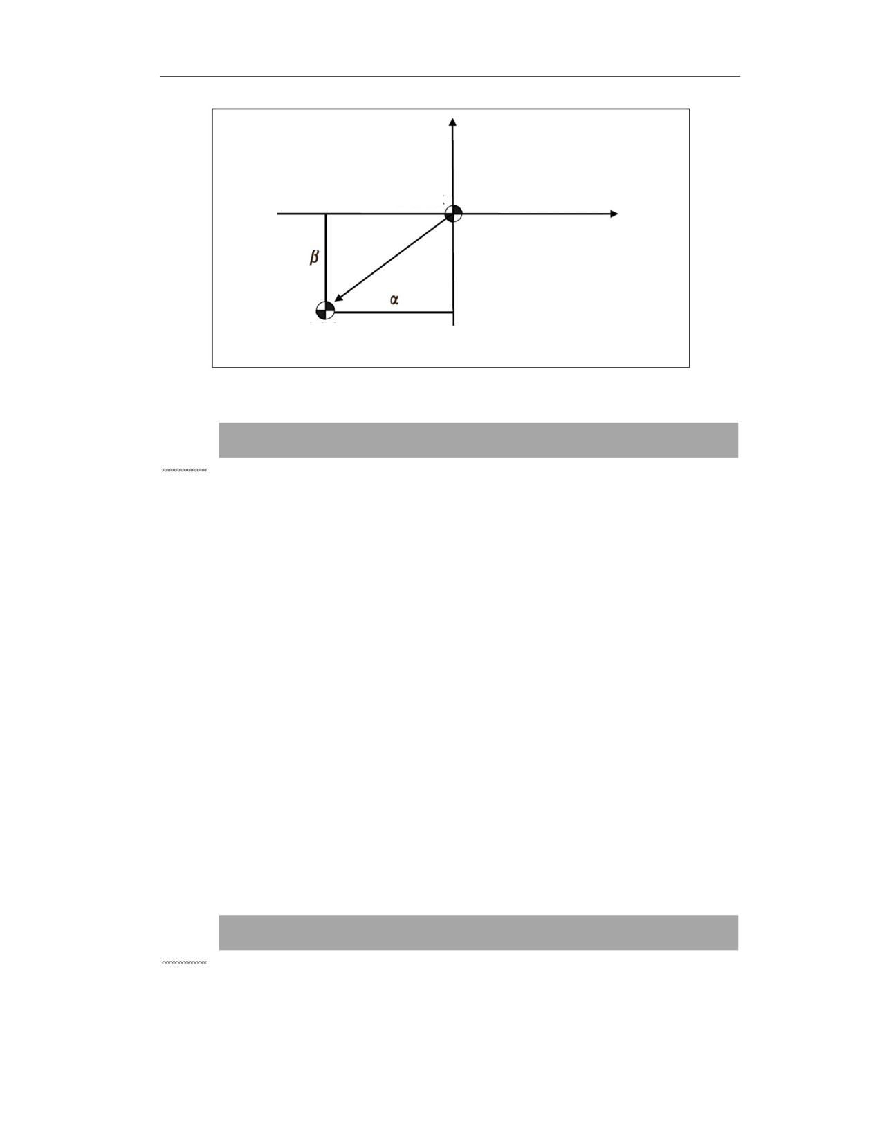
Machine origin
Reference point
10.3
Workpiece Coordinate System
Function and Purpose
The workpiece coordinate system is used by the programmer during programming. The
programmer selects a known point on the workpiece as the zero of the workpiece coordinate
system. The introduction of the workpiece coordinate system is to simplify programming and
reduce calculations.
There are three ways to establish a workpiece coordinate system:
(1) Use the workpiece coordinate system setting command (G92) to establish a workpiece
coordinate system;
(2) Use the workpiece coordinate system selection commands (G54~G59) to establish a
workpiece coordinate system;
(3) Use the extended workpiece coordinate system selection command (G54.01~G54.60) to
establish a workpiece coordinate system;
For the lathe, in the absolute tool offset compensation mode, the workpiece coordinate zero can
be set with the T command.
In addition, the zero of workpiece coordinate system established in the above ways can be
modified by G10 command, and a new workpiece coordinate system can be formed.
10.3.1 Workpiece Coordinate System Setting (G92)
Function and Purpose
The meaning of the G92 command is to determine the position of the workpiece origin through
the coordinate value of the tool location in the workpiece coordinate system. The position of the
workpiece coordinate system changes with the change of the tool position when this command is
78
executed. The prerequisite for correct processing is that the operator must correctly set the tool
position on the set coordinates through the tool setting.
Command Format
G92 IP(X…Y…Z…)_;
Parameter
Meaning
IP
The directed distance from the origin of the
coordinate system to the starting point of the
tool
Before executing the program containing the G92 command, user must perform the tool setting
operation to ensure that the workpiece coordinate system origin established by the G92 command
is consistent with the programmed origin.
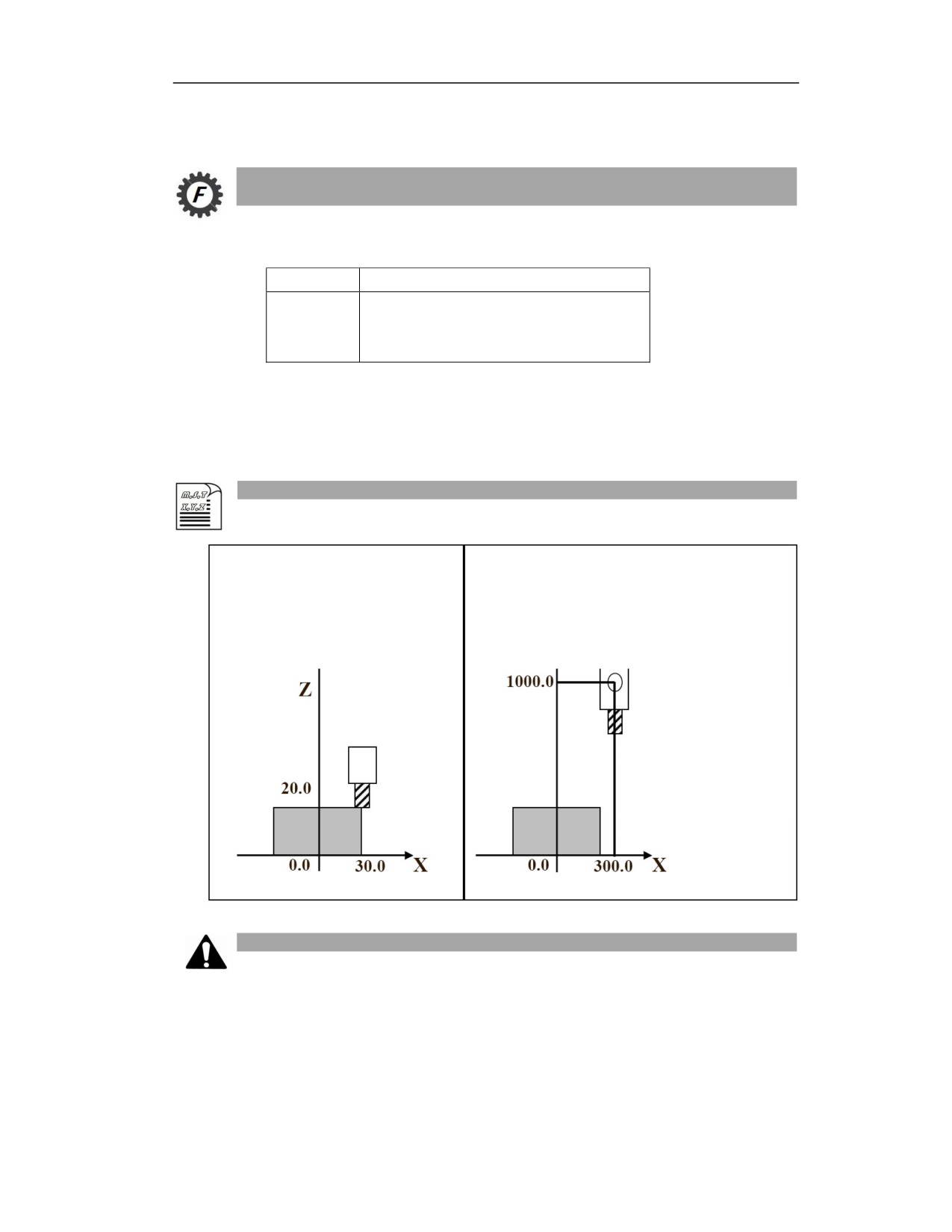
Example
Example
1:
use G92X30.0Z20.0;
Example 2: use G92X300.0Z1000.0; command to
command to set the coordinate system
set the coordinate system (The starting point of
(tool nose is the starting point of program)
program is the reference point on shank)
To move the tool nose to
the command position in
absolute
programming,
perform the tool length
compensation for the
difference between the
tool nose and reference
point
Note
1) When executing this block, only the workpiece coordinate system is established, and the tool
does not move;
2) G92 is a non-modal command;
3) After the length compensation is added, if the coordinate system is set by the G92 command,
the set coordinate system is the coordinate position before compensation. However, the G92
79