HNC8 Series CNC Controller. Programming Manual (V2.4) - page 1
HNC8 Series CNC Controller
Programming Manual
V2.4
Content
Introduction _____________________________________________________________________ i
Content __________________________________________________________________________ ii
1 Overview __________________________________________________________________________7
1.1
Coordinate Axis _________________________________________________________________________ 7
1.1.1 Machine Coordinate Axis _________________________________________________________________ 7
1.1.2 CNC Control Axis _________________________________________________________________________ 7
1.2
Reference Point, Machine Origin, and Machine Coordinate System _____________________ 9
1.3
Workpiece Origin and Workpiece Coordinate System _________________________________ 10
1.4
Coordinate System and Travel _________________________________________________________ 10
1.5
Positional Relationship between Coordinate Systems __________________________________11
1.7
General Programming Methods and Steps _____________________________________________12
2 Program Format and Structure _________________________________________________ 13
2.1
Program Format ________________________________________________________________________13
2.1.1 Address and Command Word ___________________________________________________________13
2.1.2 Block and Block Number ________________________________________________________________15
2.1.3 General Structure of Program ___________________________________________________________16
2.1.4 File Attributes of Program _______________________________________________________________ 16
2.1.5 Program and Program Name____________________________________________________________17
2.1.6 Optional Block Skip ______________________________________________________________________18
2.2
Main Program and Subprogram _______________________________________________________18
2.3
Cautions before Machining_____________________________________________________________ 20
3 Preparatory Function (G Code) _________________________________________________ 21
3.1
G Code Modal and Grouping __________________________________________________________21
3.2
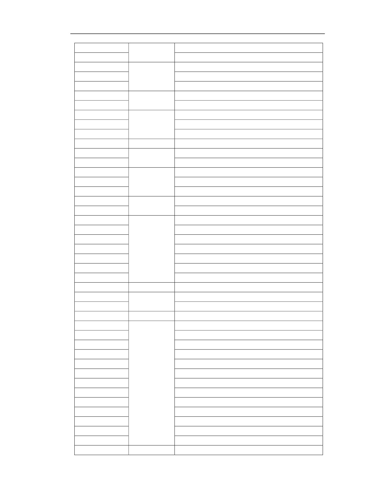
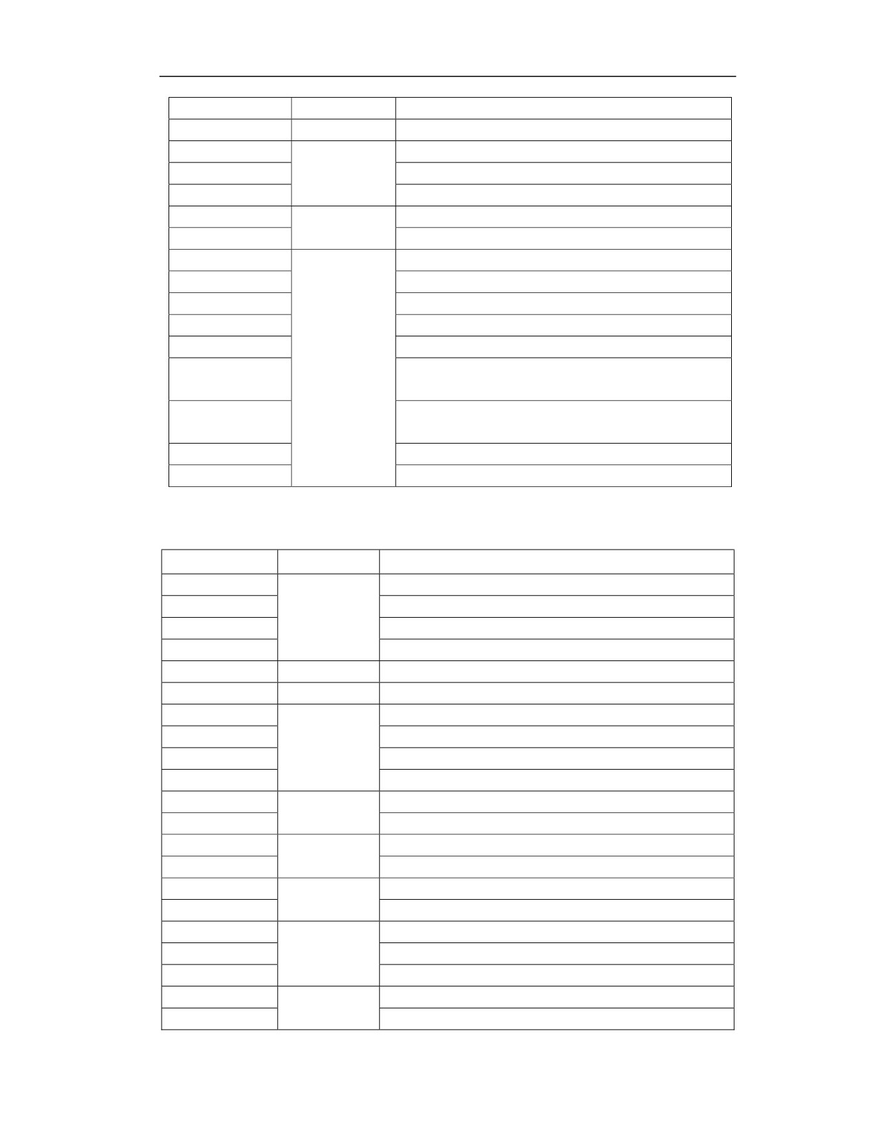
List of G codes (T) ______________________________________________________________________21
3.3
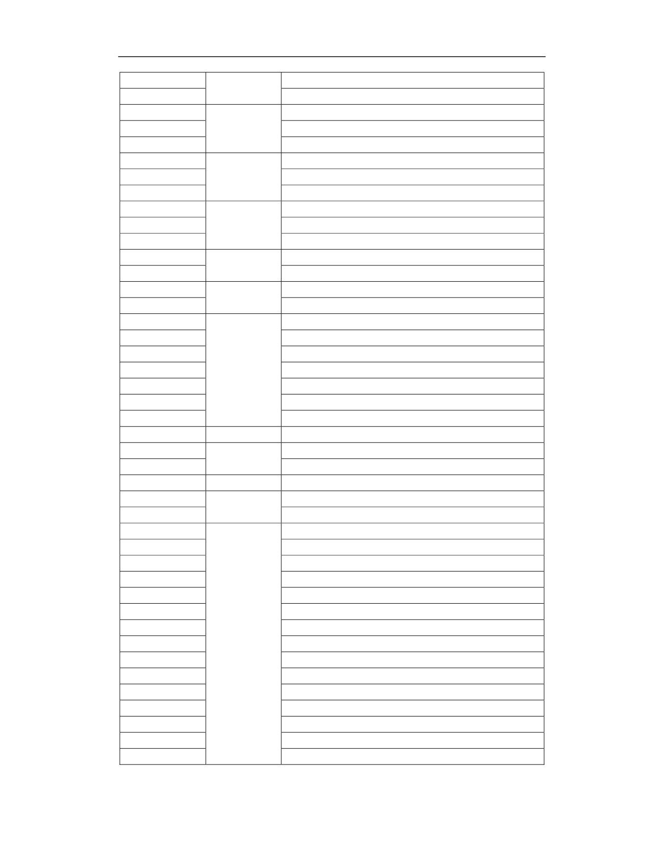
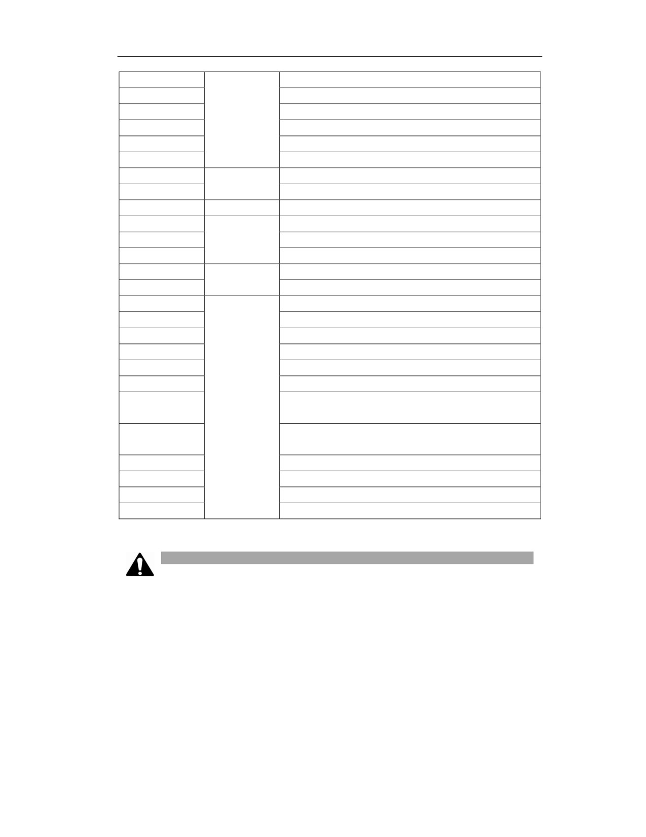
List of G codes (M) _____________________________________________________________________23
4 Auxiliary Function _______________________________________________________________ 26
4.1
M Command ___________________________________________________________________________ 26
4.1.1 Default Auxiliary Function of CNC _______________________________________________________28
4.1.2 Auxiliary Function Set by PLC ____________________________________________________________31
4.2
Table of M Command Function and Regular Status ____________________________________ 32
5 Spindle Function ________________________________________________________________ 35
5.1
Spindle Speed Setting __________________________________________________________________35
5.2
Constant Linear Speed Cutting Control(G96/G97
(T) _____________________________36
5.3
Spindle Clamping Speed _______________________________________________________________38
5.4
C/S-Axis Switching(CTOS/STOC)____________________________________________________39
5.5
Spindle Orientation_____________________________________________________________________40
ii
5.6
Spindle Synchronization Control(G146/G147) ______________________________________41
6 Tool Function ___________________________________________________________________ 46
6.1
T Command in Lathe System ___________________________________________________________ 46
6.2
T Command in Milling System__________________________________________________________ 49
7 Feed Function ___________________________________________________________________ 52
7.1
Overview _______________________________________________________________________________52
7.2
Feedrate Setting ________________________________________________________________________ 53
7.2.1 Rapid Traverse Speed ___________________________________________________________________ 54
7.2.2 Cutting Feedrate_________________________________________________________________________55
7.2.3 2nd Feedrate ____________________________________________________________________________58
7.3
Feed Control Mode_____________________________________________________________________ 58
7.4
Feedrate Control _______________________________________________________________________ 61
8 Position Command Function ___________________________________________________ 65
8.1
Mode I of Absolute Command and Incremental Command(G90/G91) _____________65
8.2
Mode II of Absolute Command and Incremental Command (X, Z/U, W)(T) ______67
8.3
Diameter Programming and Radius Programming(G36/G37
(T) _________________69
8.3
Inch/Metric(G20/G21) _______________________________________________________________71
9 Delay Function __________________________________________________________________ 73
9.1
Delay Function _________________________________________________________________________ 73
10
Coordinate System ___________________________________________________________ 75
10.1
Overview ______________________________________________________________________________ 75
10.2
Machine Coordinate System __________________________________________________________76
10.3
Workpiece Coordinate System ________________________________________________________ 78
10.3.1 Workpiece Coordinate System Setting (G92) ___________________________________________ 78
10.3.2 Workpiece Coordinate System Selection G54~G59(G54.X) ________________________ 80
10.3.3 Extended Workpiece Coordinate System Selection(G54.x) __________________________81
10.3.4 Workpiece Coordinate System Modification (G10) _____________________________________82
10.4
Local Coordinate System Setting (G52) _______________________________________________83
10.5
Coordinate Plane Selection(G17,G18,G19) _____________________________________86
10.6
Machine Origin and 2nd, 3rd, 4th, and 5th Reference Points _________________________87
10.7
Reference Point Return (G28/G29) ____________________________________________________88
10.8
2nd, 3rd, 4th,5th Reference Point Return (G30) ____________________________________________ 91
11
Interpolation Function________________________________________________________ 94
11.1
Positioning (G00) ______________________________________________________________________94
11.2
Unidirectional Positioning (G60) ______________________________________________________97
11.3
Linear Interpolation (G01) _____________________________________________________________99
11.4
Circular Interpolation(G02/G03) _________________________________________________ 102
11.5
3D Circular Interpolation(G02.4/G03.4) __________________________________________ 107
11.6
Thread Cutting(G32)(T) ________________________________________________________ 109
11.7
Helical Interpolation(G02/G03) __________________________________________________ 112
11.8
Imaginary Axis Specifying and Sine Interpolation (G07) _____________________________ 114
iii
11.9
Polar Coordinate Interpolation(G12/G13) _______________________________________ 116
11.10
Cylindrical interpolation(G07.1)_________________________________________________ 121
11.11
Polar Coordinate Command(G15/G16)_________________________________________ 124
11.12
NURBS Spline Interpolation ________________________________________________________ 130
11.13
HSPLINE Spline Interpolation ______________________________________________________ 132
12
Tool Compensation Function________________________________________________
135
12.1
Turning Tool offset Compensation(T)____________________________________________ 135
12.2
Turning Tool Nose Radius Compensation(G40/G41/G42)(T) __________________ 138
12.3
Milling Tool Length Compensation(M) __________________________________________ 144
12.4
Milling Tool Radius Compensation(G40/G41/G42
(M) ________________________ 153
12.5
Detailed Explanation of Tool Radius Compensation ________________________________ 157
12.5.1 Tool Radius Compensation Action ___________________________________________________ 157
12.5.2 Tool Radius Compensation Action Diagram__________________________________________ 159
12.5.3 Compensation Direction Change During Tool Radius Compensation ________________ 165
12.5.4 When Tool Radius Compensation is not Executed ___________________________________ 167
12.5.5 There is a Block without movement in Tool Radius Compensation___________________ 169
12.5.6 Action Insertion in Tool Radius Compensation _______________________________________ 171
12.5.7 Change of Compensation Value in Tool Radius Compensation ______________________ 172
12.5.8 Interference Check ___________________________________________________________________ 173
13
Programmable Data Input(G10/G11) ____________________________________
176
13.1
Programmable Data Input Command(G10/G11) ________________________________ 176
13.2
Workpiece Coordinate System Origin Input_________________________________________ 176
13.3
Extended Workpiece Coordinate System Origin Data Input ________________________ 177
13.4
System Parameter Data Output _____________________________________________________ 178
13.5
Milling Tool Length Compensation Data Input ______________________________________ 179
13.6
Milling Tool Radius Compensation Data Input ______________________________________ 180
13.7
Lathe Tool Offset Data Input ________________________________________________________ 181
13.8
Get and Modify Single Cutting Time ________________________________________________ 182
14
Standard Canned Cycle of Lathe(T) ______________________________________
183
14.1
Simple Cycle of Lathe _______________________________________________________________ 183
14.1.1 Inner (Outer) Diameter Cutting Cycle ________________________________________________ 183
14.1.2 End Face Cutting Cycle (G81) ________________________________________________________ 187
14.1.3 Thread Cutting Cycle(G82) ________________________________________________________ 189
14.1.4 End Face Deep-hole Drilling Cycle(G74) __________________________________________ 192
14.1.5 Outer Diameter Grooving Cycle (G75) _______________________________________________ 194
14.2
Drilling Canned Cycle for Lathe System _____________________________________________ 197
14.2.1 Axial Drilling Cycle(G83)/Radial Drilling Cycle(G87)____________________________ 197
14.2.2 Axial Rigid Tapping Cycle (G84)/ Radial Rigid Tapping Cycle (G88) __________________ 202
14.3
FANUC Mode of Lathe System ______________________________________________________ 204
15
Canned Cycle for Milling System (M) _______________________________________
207
15.1
Standard Canned Cycle for Milling System__________________________________________ 207
15.2
High-speed Deep-hole Drilling Cycle(G73)______________________________________ 212
iv
15.3
Reverse Tapping Cycle(G74) _____________________________________________________ 216
15.3.1 Reverse Tapping Cycle _______________________________________________________________ 216
15.3.2 Reverse Peck Tapping Cycle__________________________________________________________ 217
15.4
Fine Boring(G76) _________________________________________________________________ 221
15.5
Drilling Cycle (Center Drills)(G81) ________________________________________________ 225
15.6
Drilling Cycle with Pause(G82) ___________________________________________________ 228
15.7
Deep Hole Drilling Cycle (G83) ______________________________________________________ 230
15.8
Tapping Cycle (G84) ________________________________________________________________ 233
15.8.1 Tapping Cycle(G84) _______________________________________________________________ 234
15.8.2 Peck Tapping Cycle (G84) ____________________________________________________________ 235
15.9
Boring Cycle (G85) __________________________________________________________________ 238
15.10
Boring Cycle (G86) _________________________________________________________________ 241
15.11
Reverse Boring Cycle (G87) ________________________________________________________ 244
15.12
Boring Cycle (Manual) (G88) _______________________________________________________ 247
15.13
Boring Cycle (G89) _________________________________________________________________ 250
15.14
Drilling Canned Cycle Cancel (G80) ________________________________________________ 252
16
Extended Canned Cycle(M) ______________________________________________
254
16.1
Extended Canned Cycle (M) _________________________________________________________ 254
16.2
Engraving Canned Cycle (G1025) ___________________________________________________ 254
16.3
Drilling Type ________________________________________________________________________ 259
16.3.1 Circumferential Hole Drilling Cycle (G70)_____________________________________________ 259
16.3.2 Circular Hole Drilling Cycle (G71)_____________________________________________________ 263
16.3.3 Straight Line Hole Cycle (G78)________________________________________________________ 266
16.3.4 Chess Type Hole Cycle (G79) _________________________________________________________ 269
16.4
Milling Cycle ________________________________________________________________________ 272
16.4.1 Circular Groove Milling Cycle (Type 1) (G181) ________________________________________ 272
16.4.2 Circular Groove Milling Cycle (Type 2) (G182) ________________________________________ 275
16.4.3 Circumferential Groove Milling Cycle (G183) _________________________________________ 279
16.4.4 Rectangular Pocket Milling Cycle (G184) _____________________________________________ 283
16.4.5 Circular Pocket Milling Cycle (G185)__________________________________________________ 287
16.4.6 End Face Milling Cycle(G186) _____________________________________________________ 290
16.4.7 Rectangular Boss Milling Cycle (G188) _______________________________________________ 293
16.4.8 Round Boss Milling Cycle (G189) _____________________________________________________ 297
16.4.9 Milling Cycle Alarm Diagnosis ________________________________________________________ 301
17
Multiple Repetitive Cycle in Lathe(T) ____________________________________
306
17.1
Inner (Outer) Diameter Roughing Multiple Repetitive Cycle (G71) __________________ 306
17.2
End Face Roughing Multiple Repetitive Cycle (G72) ________________________________ 313
17.3
Closed Turning Multiple Repetitive Cycle (G73) _____________________________________ 317
17.4
Thread Cutting Multiple Repetitive Cycle (G76) _____________________________________ 321
18
Programming Simplifying Function (M) ____________________________________
324
18.1
Mirroring Function(G24,G25) __________________________________________________ 324
18.2
Scaling Function(G50,G51) _____________________________________________________ 330
v
18.3
Rotation Transformation(G68,G69) ____________________________________________ 334
19
User Macro and Subprogram Calling _______________________________________ 337
19.1
User Macro Program ________________________________________________________________ 337
19.1.1 Variable ______________________________________________________________________________ 337
19.1.2 Operation Command_________________________________________________________________ 346
19.1.3 Macro Statement _____________________________________________________________________ 349
19.2
Macro Program Calling _____________________________________________________________ 353
19.2.1 Argument Specification Rules ________________________________________________________ 353
19.2.2 Non-modal Call (G65)________________________________________________________________ 354
19.2.3 Calling Macro Program with G Code _________________________________________________ 355
19.2.4 Calling Macro Program with M Command ___________________________________________ 356
19.2.5 Classification of Subprogram _________________________________________________________ 359
19.2.6 Macro Program Example _____________________________________________________________ 360
19.3
Manual Calling Subprogram ________________________________________________________ 362
20
High-speed High-Precision Function _______________________________________ 364
20.1
Machining Optimization Function G125/G126 ______________________________________ 364
20.2
High Speed High Precision Mode Selection(M
(G05.1) ________________________ 373
20.3
High Speed High Precision Parameter Setting ______________________________________ 376
vi
1 Overview
1.1
Coordinate Axis
1.1.1 Machine Coordinate Axis
Function and Purpose
In order to simplify programming and ensure the versatility of the program, a unified standard has
been formulated for the naming of coordinate axes and directions of CNC machine tools.
The fixed linear feed coordinate axes are represented by X, Y, Z which are referred to as the basic
coordinate axes; the coordinate axes rotating around the X, Y, and Z axes are represented by A, B,
and C which are referred to as the rotary coordinate axes.
1) Basic coordinate axes X, Y, Z
The direction of the machine tool axis depends on the type of machine tool and the layout of each
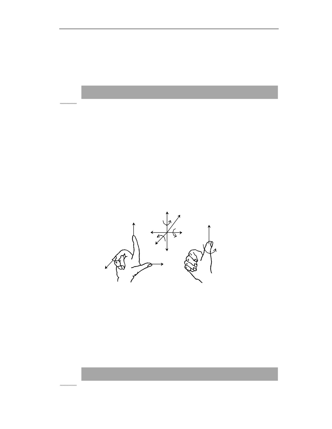
component. The relationship between the X, Y, and Z coordinate axes is determined by the right-
hand rule, as shown in Figure 1-1. In this figure, the thumb points in the positive direction of X
axis, the index finger points in the positive direction of Y axis, and the middle finger points in the
positive direction of Z axis.
+Y
+B
+Z'
+X +Y +Z
+Y
+X'
+X
+C
+A
+Z
+A +B
+Y'
+C
+X
+Z
Figure 1-1 Machine coordinate axis
2) Rotary axis
The circular feed coordinate axes that rotate around the X, Y, and Z axes are represented by A, B,
and C respectively. According to the right-hand screw rule as shown in Figure 1-1, the thumb
points to +X, +Y, +Z directions, and the index finger and middle finger point to +A, +B, +C
directions of circular feed motion.
1.1.2 CNC Control Axis
Function and Purpose
7

The standard HNC8 CNC controller has 3 axes; it can control up to 5 axes by adding auxiliary
axes. When specifying each machining axis and direction, use the preset coordinate letter and
the set direction.
Item
HNC-8 (Standard)
Basic controlled axes
3 axes
Extended controlled axes (total)
5 axes at maximum (including CS axis)
Basic simultaneously-controlled axes
3 axes
Extended simultaneously-controlled axes
5 axes at maximum
Axis name: 3 standard basic axes are X, Y, Z, and the the additional axes can be named A, B, C,
U, V, W.
Note: The additional axis names U, V, W can be set by the parameters, and are not related to the
UVW instruction words during lathe incremental programming. For details, see the instructions
on lathe incremental programming.
8
1.2
Reference Point, Machine Origin, and Machine Coordinate System
Function and Purpose
Reference point: The machine reference point is a fixed mechanical point on the machine tool
(For some machine tools it is determined by the travel switch and dog, and for some machine tools
it is directly determined by the grating ruler zero, etc.)
Machine origin: The machine zero is a fixed point on the machine tool, and the CNC device uses
it as a reference for position control. The machine zero is determined by the reference point and
the system parameter "coordinate value of reference point in machine coordinate system".
Machine coordinate system: The machine coordinate system is the inherent coordinate system
of the machine tool. It takes the machine zero as the origin, and each coordinate axis is parallel to
the corresponding machine axis. The origin of the machine coordinate system is also called the
machine origin or machine zero. In the machine coordinate system, the workpiece is always
considered to be stationary, while the tool is considered to be moving.
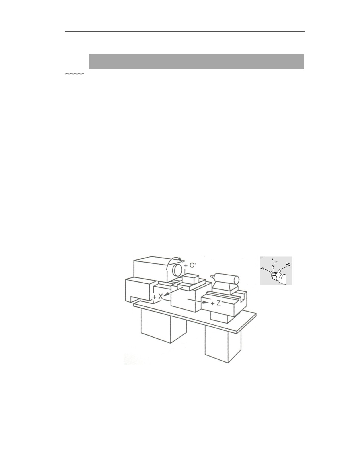
Figure 1-2 shows the horizontal lathe with front tool post. Since it is a machine tool with a rotary
spindle, first user determines the Z-axis direction: the spindle axis direction is the Z-axis direction,
and the direction the tool moves away from the workpiece is the positive direction of Z-axis; then
user determines the X-axis direction: in the machining plane of the machine tool, the direction
perpendicular to the Z-axis is the X-axis direction, and the direction the tool moves away from the
workpiece is the positive direction of X-axis; At last user determines the Y-axis direction: the Y-
axis positive direction can be determined based on the right-hand Cartesian rule.
Figure 1-2 Horizontal lathe with front tool post
Figure 1-3 shows a single-column vertical milling machine (or machining center). Since it is a
machine tool with a rotary spindle, first user determines the Z-axis direction: the spindle axis
direction is the Z-axis direction, and the direction the tool moves away from the workpiece is the
Z-axis positive direction; then user determines the X-axis direction: while the operator is facing
the column and the worktable is moving, relative to the workpiece the direction of the tool moving
9
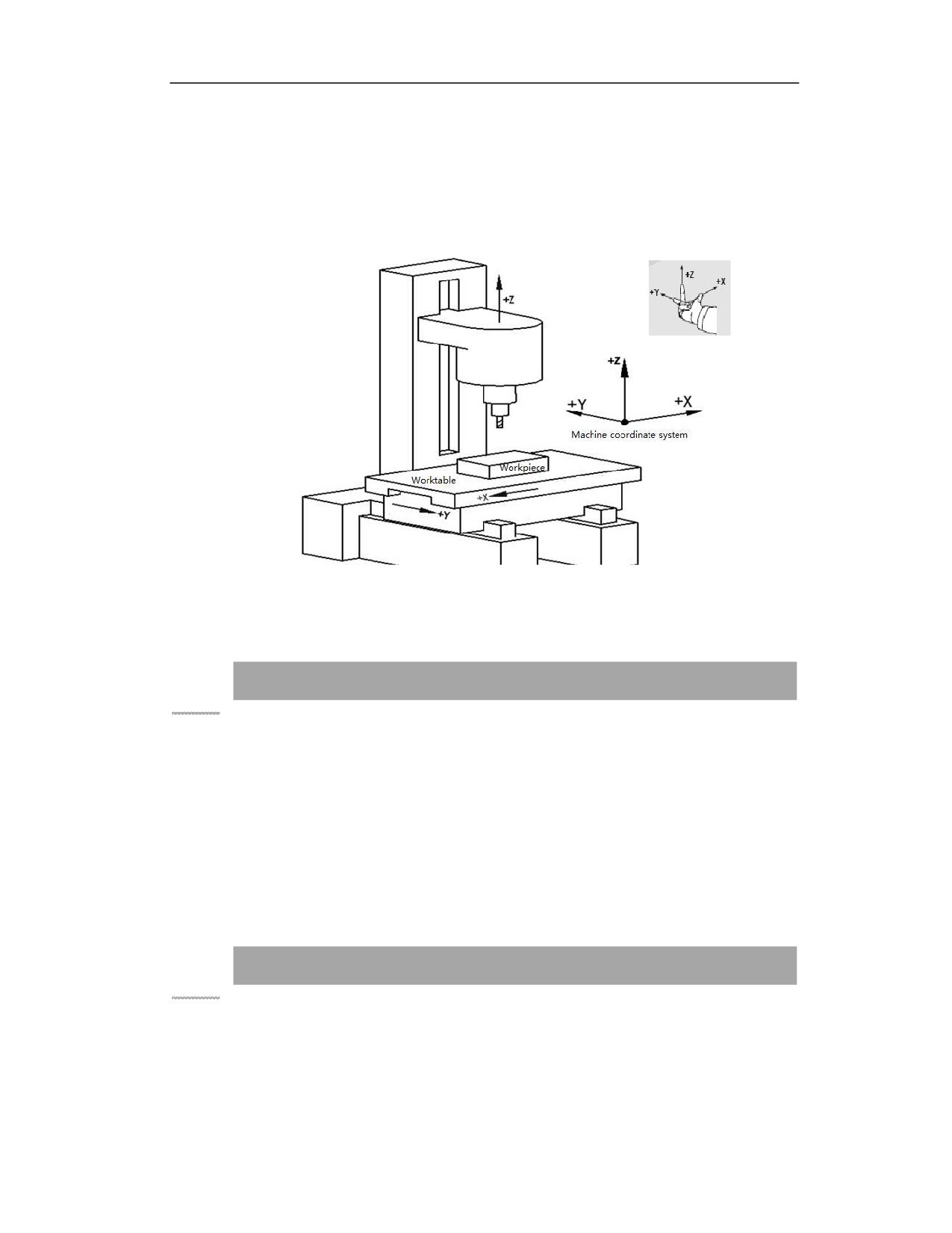
to the right is the X-axis positive direction; at last user determines the direction of the Y axis:
according to the right-hand Cartesian rule, the positive direction of Y-axis is the direction tool
moves to the column relative to the workpiece.
Taking the machine zero point as the origin, the coordinate system established with each axis of
the machine tool is the machine coordinate system of the machine tool.
Figure 1-3 Vertical milling machine with single column
1.3
Workpiece Origin and Workpiece Coordinate System
Function and Purpose
The workpiece coordinate system is used by the programmer during programming. The
programmer selects a known point on the workpiece as the origin (also referred to as the program
origin), and establishes a coordinate system parallel to each axis of the machine tool, which is
called the workpiece coordinate system. Once the workpiece coordinate system is established, it
will remain valid until it is replaced by a new workpiece coordinate system.
The workpiece coordinate system is determined by the programmer, and generally a position that
is convenient for processing and calculation is selected.
1.4
Coordinate System and Travel
Function and Purpose
The travel of the machine tool coordinate system is divided into effective travel and mechanical
travel. The effective travel is the range of tool movement which is set by CNC parameters; the
mechanical travel is determined by the travel switch, and its value is determined by the
manufacturer. The relationship between the machine zero (M), machine reference point (m),
workpiece coordinate origin (W), effective travel and mechanical travel of the machine coordinate
10
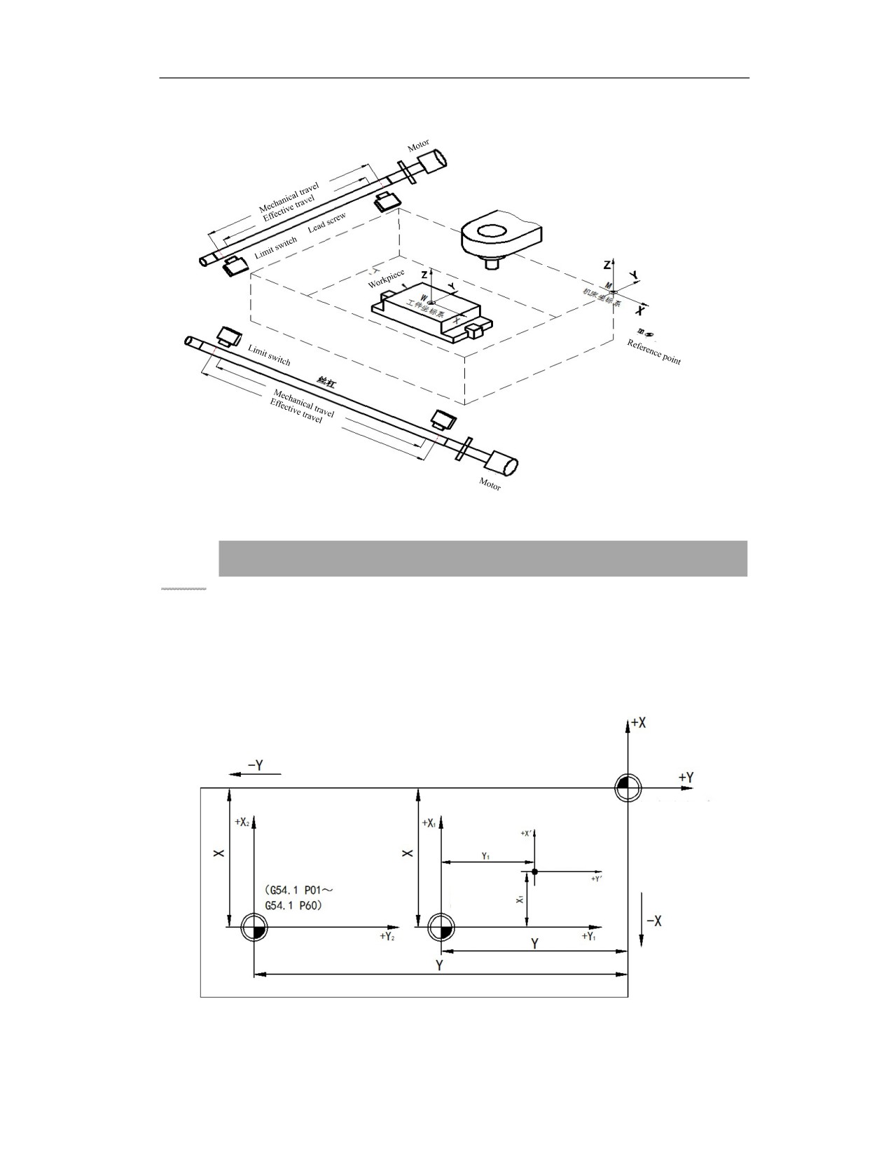
system is shown in the figure below.
W: workpiece coordinate system
M: machine coordinate system
1.5
Positional Relationship between Coordinate Systems
Function and Purpose
The coordinate system set with the machine zero as the origin is referred to as the machine
coordinate system. The machine tool manufacturer sets the machine zero for each machine tool.
The workpiece coordinate system is the coordinate system used in workpiece processing.
Generally, their position setting relationship is shown in the figure below.
Machine coordinate system
Local
coordinate
system (G52)
Workpiece coordinate system
Workpiece
coordinate
system
(G54 - G59)
11
1.7
General Programming Methods and Steps
Function and Purpose
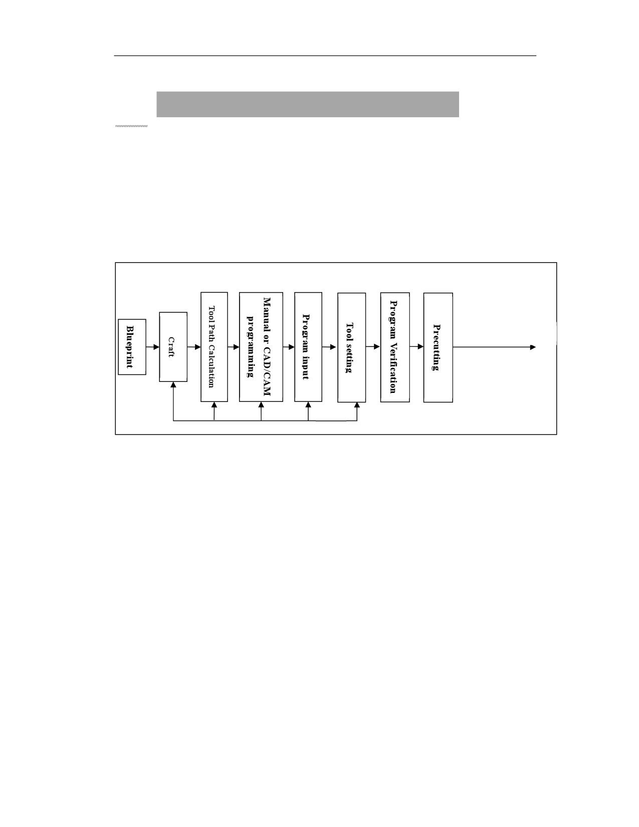
Programming means that the programmer determines the processing technology of the parts based
on the drawing. The processing process, process parameters, processing path and auxiliary actions
required in processing such as tool change, cooling, clamping, etc. are documented as the program
list in accordance with the processing sequence and the command code and program format
specified by the CNC machine tool used. Then all the contents in the program list are input into
the CNC controller, so that the CNC machine tool can process based on the contents.
The general methods and steps for programming and processing are as follows:
Batch Machining
Edit
12
2 Program Format and Structure
2.1
Program Format
Function and Purpose
When providing information to a controller, the format specified is referred to as the program
format. The format used by the controller is referred to as the word address format.
A program is a collection of "block" units, and a "block" is used to specify a machine action
(sequence). These commands (blocks) are worked out in the order of actual tool movement. A
program block is a collection of "word" units, and a "word" is used to specify a command of an
operation. A word is a collection of characters (English letters, numbers, symbols), and the
characters are arranged in a certain order.
2.1.1 Address and Command Word
Function and Purpose
The command information used by this controller consists of letters (A, B, C...Z), and numbers
(0, 1, 2...9), and symbols (+, -, /...). These letters, numbers, and symbols are collectively referred
to as characters. What is expressed in this form is referred to as a code. This controller uses ISO
code which is written in notepad format.
Description
The initial letter of a word is referred to as the address, which defines the meaning of the following
numerical information. A command word is composed of address characters (command characters)
and numeric data with signs (such as the word with a defined dimension) or without signs (such
as the preparatory function word G code). In this controller, the word is composed of a letter
(word address) and several numbers following it. (User can also add symbols such as "-" at the
beginning of the number).
13
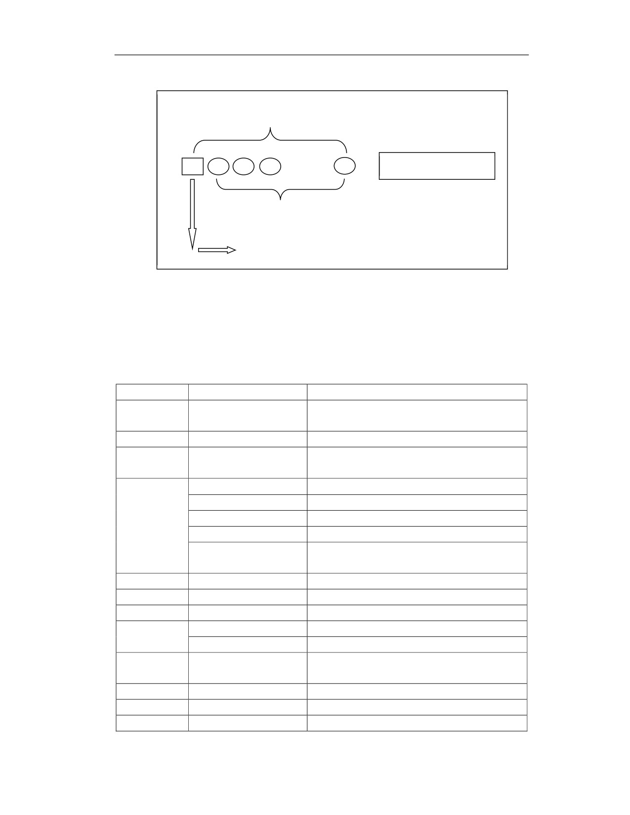
Word
For example, X153.7
Number
Letter(Word address)
Structure of word
Different command characters and the subsequent numbers in the block determine the meaning
of each command word. The main command characters contained in the CNC program block are
shown in Table 2.1.
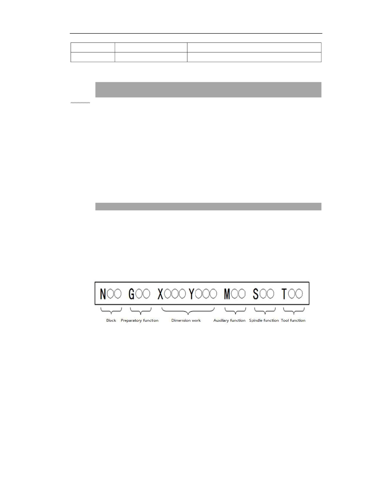
Table 2.1 List of command characters
Function
Address
Meaning
Parts program
Letter O
Program No.:O1~4294967295
No.
Block No.
N
Block No.:N0~4294967295
Preperatary
G
Command action mode (straight line, circular arc, etc.):
function
G00 to G200
X,Y,Z
Traverse command of linear axis: ±21474
A,B,C
Traverse command of rotary axis: ±21474
Dimension word
U,V,W
Incremental programming command of lathe: ±21474
R
Circular radius of canned cycle
I,J,K
Coordinates of circle center relative to the starting point
for canned cycle
Feedrate
F
Feedrate:0 to 50000
Spindle function
S
Spindle speed:0 to 100000
Tool function
T
Tool number:0 to 99
Auxiliary
M
ON/OFF control at the machine side:0 to 99
function
A
Worktable indexing
Compensation
H,D
Tool compensation number:00 to 99
No.
Dwell
P,X
The dwell time: millisecond, second
Program No.
P
Sub-program number:1 to 4294967295
Repeat times
L
The number of repetitions of subprogram, the number of
14
repetitions of canned cycle
Parameter
P,Q,R
Canned cycle parameter
2.1.2 Block and Block Number
Function and Purpose
The composition of the block: A program block is composed of more than one word. A group of
single-step sequential commands or a line of several functional commands is referred to as a
program block.
Block number: the number used to distinguish each block, which is composed of address N and
the following 5 digits (1 to 99999). The block number is placed at the beginning of the block, and
can be specified in any order. Any block number can be skipped except for the block number
specified by the code command with special meaning. The block number can be specified for all
blocks, and also can be specified only for the blocks required by the program. However, for
convenience, in general the block number is specified in the order of processing steps.
Descriptions
A program block defines a command line to be executed by the CNC controller. The format of
the block defines the syntax of the functional words in each block.
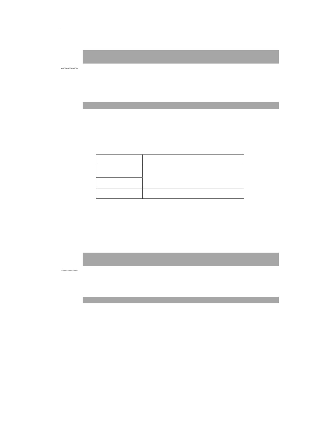
The structures of block number and block are as follows:
1 block (or command line)
E.g. N100 G01 X24.7 Y59.31 M03 S1000 T0101; the part underlined is the block number
A block starts with the sequence number that identifies the block (the block number can also be
absent), and ends with the block end code. In this manual, a newline indicates the end of the block.
Like a notepad, a newline character indicates the end of the line. The preliminary function
determines the content of the dimension character. In this manual, the dimension words are
represented by IP.
15
2.1.3 General Structure of Program
Function and Purpose
A program of parts is executed in the order of the block line, not in the order of the block number,
but it is recommended to write the block number in ascending order when writing the program.
Description
Program start: The first cell of the first line cannot be numbers or symbols other than "%".
Program end: the program end code is usually specified at the end of the program, and one of the
following codes is to indicate the program end code.
Code
Meaning
M02
End of main program
M30
M99
End of subprogram
Comment symbol: the content bracketed () or after the semicolon ";" is the comment text.
Single line command: When writing the processing G code program, some commands must be
written in a single line. Such as M30, M02, M99, M6T, CTOS, STOC, G16, G15, G05.1, G04.
2.1.4 File Attributes of Program
Function and Purpose
User can set the access attribute for the file program to be writable or readable.
Description
Editing prohibited: The current loader can be set to "read-only" through interface operations. At
this time, the file cannot be rewritten until it is set to "writeable" through interface operations.
In addition, user can also control the access properties of the program through the key switch of
the project panel, but this key switch is effective on all programs in the program manager, that is,
when the switch is turned off, all programs will become read-only until the switch is turned on.
16
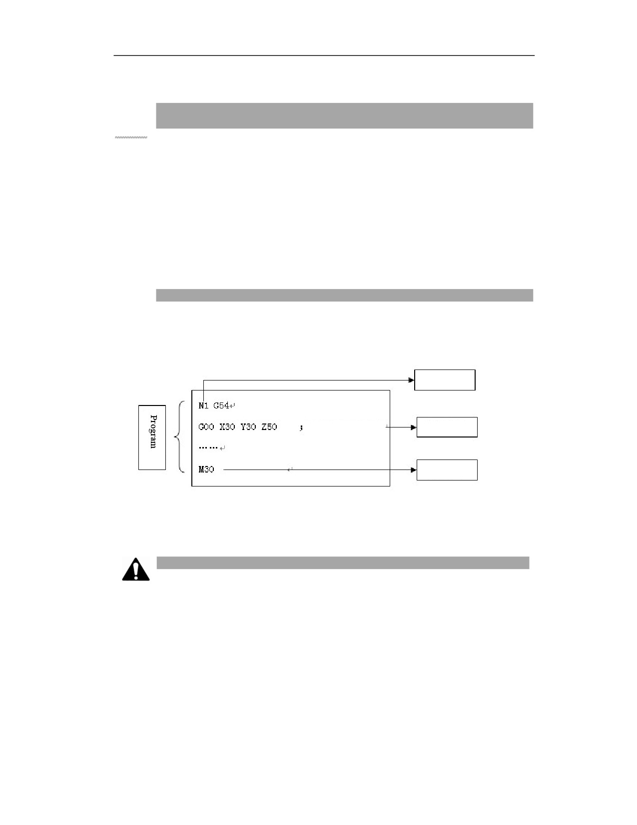
2.1.5 Program and Program Name
Function and Purpose
Program: A parts program is composed of several blocks that follow certain structure, syntax and
format rules, and each block is composed of several command words. The program name
corresponds to each workpiece, or is a number to classify programs in the unit of subprogram. The
program name is a number used to distinguish each program. Use the address "O" (capital letter
O) and the following number or letter to specify.
The newly created program name on the system can be up to 7 numbers or letters; the system can
read the program name created externally with greater than 7 characters.
Description
This system calls the program by calling the program name for processing or editing.
Block No.
The starting position
Comment
Program end
If the program end code is executed during the program execution, the CNC ends the program
execution and goes into the reset state. When the subprogram end code is executed, the control
returns to the main program that calls the subprogram.
Note
If the Optional Skip switch on the machine operation panel is turned on, for example,
/M02;
/M30;
/M99; Not considered to be the end of the program.
17
2.1.6 Optional Block Skip
Function and Purpose
This function means that the block after the "/" (slash) code in the processing program can be
selectively ignored until the block ends.
Description
The specific function starting with the "/" symbol. It is used to choose whether the selective
processing block is executed or not.
Detailed description: When the Optional Skip switch is ON, the line codes with the symbol "/" at
the beginning of the block are skipped; when the Optional Skip switch is OFF, the line codes with
the symbol "/" at the beginning of the block are executed, and the "/" symbol does not work.
For example, when certain blocks in the program do not need to be executed under certain
circumstances, but need to be executed in another environment, this function can be used.
Note
The ON or OFF setting of the Optional Skip button on the CNC controller must be executed before
the program runs.
The special "/" symbol for optional skip must be at the beginning of the block. (If it is inserted in
the middle of the block, it is used as a division operation command of the user macro)
Example: N30 G1 X15/Y5; error, illegal symbol alarm
/N30 G1 X15 Y5; correct
2.2
Main Program and Subprogram
Function and Purpose
When a same processing mode appears multiple times in a program, this mode can be edited into
a program for repeated calling to simplify the program. Such a program is referred to as a
subprogram, and the original program is referred to as the main program. The call of the
subprogram is performed with M98 or G65 command, and the return from the subprogram is
performed with M99 command. Refer to the chapter of user macro program for the specific
subprogram calling of G65.
The subprogram can be called repeatedly up to 999 times. User can also call other subprograms
in a subprogram, and up to 6 layers are supported.
Description
18
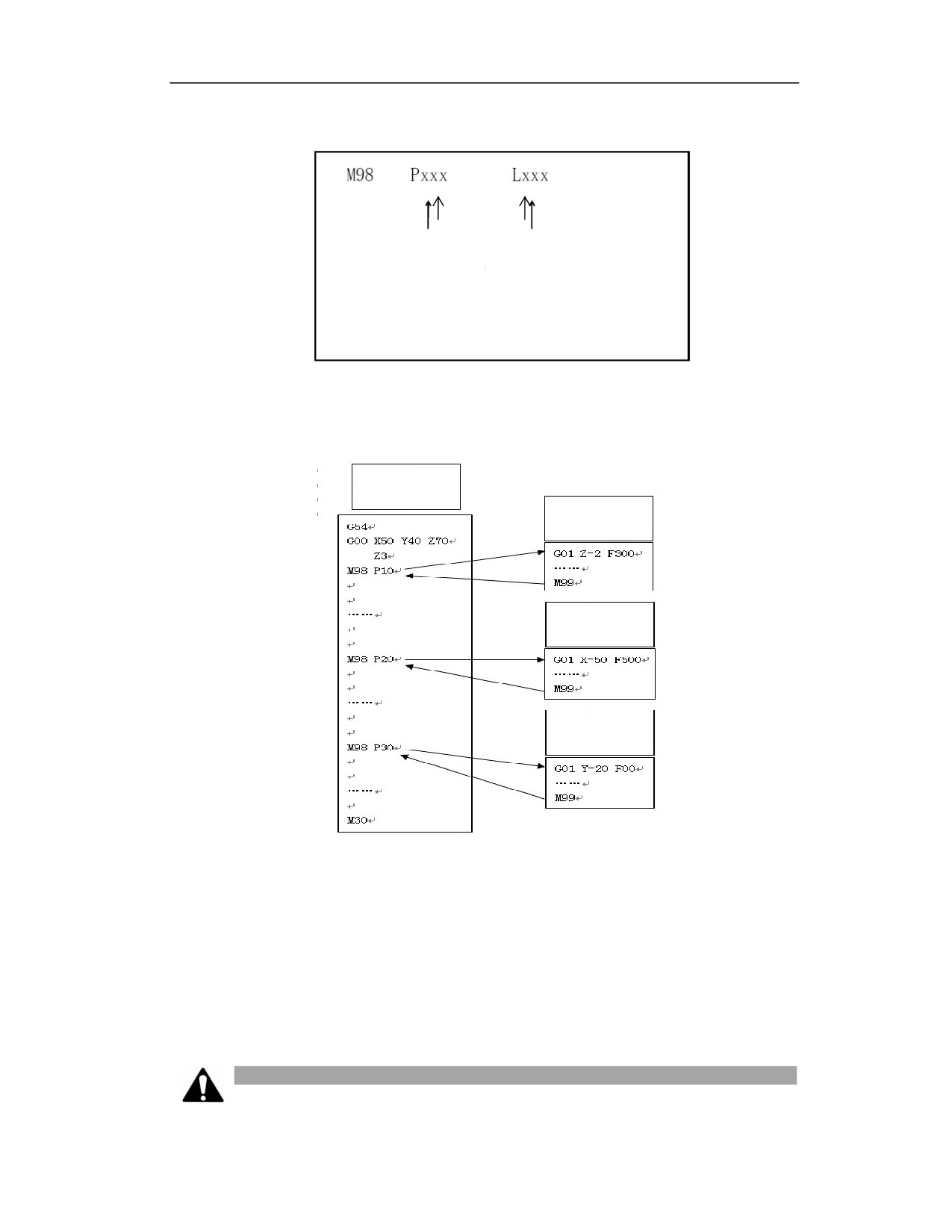
Structure of calling subprogram:
Times the subprogram
Subprogram No.
is called repeatedly
When L is not specified, that means the repetition times is
not specified, and the subprogram can only be called once
When a call to subprogram execution command occurs during the execution of the main program,
the subprogram command is executed. When the subprogram is executed, return to the main
program to continue the execution.
Main program:
O01
Subprogram:
O10
Subprogram:
O20
Subprogram:
O30
Special usage of M99: when it is used as the main program end command, return to the main
program head to execute the program again.
There are two forms to call subprogram:
1) The subprogram is placed after the main program, that is, after the end of the program (M30 or
M02). The program number called can start with % or the letter O;
2) When the subprogram is used as a separate program, it should be placed in the same disk
(system disk or USB disk) as the main program.
Note
19
1) In both forms, the subprogram placed after the main program has priority, that is, the first case
is prior to the second case.
2) When calling a subprogram, the name of the subprogram cannot have a suffix, otherwise the
alarm "File not loaded" is issued.
3) The subprogram cannot be executed in MDI, otherwise the alarm will be issued. "MDI cannot
call external subprograms".
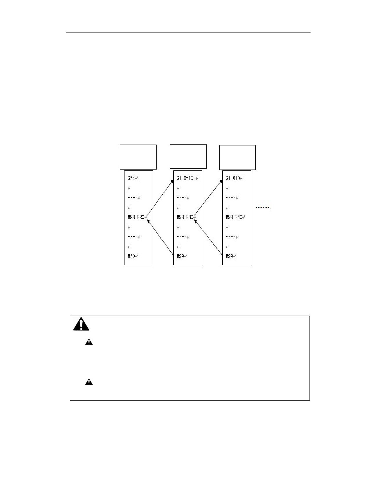
When the main program calls a subprogram, it is regarded as a first layer of subprogram, and the
called subprogram can also call another subprogram. The depth can reach up to 6 layers, as shown
below:
Subprogram:
Subprogram:
Subprogram:
O10
O20
O30
Subprogram structure nesting
2.3
Cautions before Machining
Caution
When creating a processing program, please select appropriate processing
conditions and be careful not to exceed the performance, capacity, and limitations
of the machine and NC. We do not take the above processing conditions into
consideration for the cases mentioned in this manual.
Please perform dry run before actual machining to confirm the machining program,
tool compensation amount, workpiece offset amount, etc.
20
3 Preparatory Function (G Code)
3.1
G Code Modal and Grouping
Function and Purpose
Modal of G code
G codes can be divided into two types according to their effective states: non-modal G codes and
modal G codes.
Non-modal G code: It is valid only when the G code is specified, and it is invalid if it is not
specified.
Modal G code: This type of G code is stored by the CNC system after it is executed once, and
remains valid until it is replaced by other codes in the same group.
Grouping of G codes
G codes are divided into several groups according to their functions. Group 00 is for non-modal
G codes, and the other groups are for modal G codes.
Description
1) Multiple G codes of different groups can be specified in the same block.
2) If multiple codes of the same group are specified in the same block, only the last specified code
is valid.
3) If the G code of group 01 is specified in the canned cycle, just like the G80 command is
specified, the canned cycle can be cancelled. But the G code of canned cycle does not affect the
code of 01 group.
3.2
List of G codes (T)
After the controller is powered on, the one marked with "【 】" in the table is the initial modal
in the same group, and the one marked with "『 』" is the equivalent macro name of the G code.
G code
Group No.
Function
G00
Rapid traverse positioning
【G01】
Linear interpolation
01
G02
Circular interpolation CW/ Helical interpolation CW
G03
Circular interpolation CCW/ Helical interpolation CCW
G04
00
Dwell
G07
Imaginary axis designation
G08
00
Read-ahead OFF
G09
Exact stop check
21
G10
Programmable data input
07
【G11】
Programmable data input cancel
G17
XY plane selection
【G18】
02
ZX plane selection
G19
YZ plane selection
G20
Inch input
08
【G21】
Metric input
G28
Reference point return
G29
00
Return from reference point
G30
Return from 2nd, 3rd, 4th, 5th reference points
G32
01
Thread cutting
【G36】
Diameter programming
17
G37
Radius programming
【G40】
Tool radius compensation cancel
G41
09
Left tool compensation
G42
Right tool compensation
G52
Local coordinate axis setting
00
G53
Direct machine coordinate system programming
G54.x
Extended workpiece coordinate system selection
【G54】
Workpiece coordinate system 1
G55
Workpiece coordinate system 2
G56
11
Workpiece coordinate system 3
G57
Workpiece coordinate system 4
G58
Workpiece coordinate system 5
G59
Workpiece coordinate system 6
G60
00
Unidirectional positioning
【G61】
Exact stop mode
12
G64
Cutting mode
G65
00
Macro non-modal call
G71
Inner/Outer roughing multiple repetitive cycle
G72
Face end roughing multiple repetitive cycle
G73
Close turning multiple repetitive cycle
G76
Threading cutting multiple repetitive cycle
G80
Inner/Outer diameter cutting cycle
G81
Face end cutting cycle
G82
06
Thread cutting cycle
G74
Face end deep-hole drilling cycle
G75
Outer diameter pocket cutting cycle
G83
Radial drilling cycle
G87
Axial drilling cycle
G84
Axial rigid tapping cycle
G88
Radial rigid tapping cycle
【G90】
13
Absolute programming
22
G91
Incremental programming
G92
00
Workpiece coordinate system setting
G93
Inverse time feed
【G94】
14
Feed per minute
G95
Feed per revolution
【G97】
Constant linear speed control ON
19
G96
Constant linear speed control OFF
G101
Axis release
G102
Axis acquire
G103
Command channel loader
G103.1
Command channel loader running
G104
Channel synchronization
G108
00
Spindle is switched to C axis
『STOC』
G109
C axis is switched to spindle
『CTOS』
G110
Alarm
G115
Rotary axis angle resolution redefining
3.3
List of G codes (M)
G code
Group No.
Function
G00
Rapid traverse positioning
【G01】
Linear interpolation
01
G02
Circular interpolation CW/ Helical interpolation CW
G03
Circular interpolation CCW/ Helical interpolation CCW
G04
00
Dwell
G05.1
27
High speed high precision mode
G07
Imaginary axis designation
G07.1
Cylindrical interpolation
00
G08
Read-ahead OFF
G09
Exact stop check
G10
Programmable data input
07
【G11】
Programmable data input cancel
G12
Polar coordinate interpolation ON
18
【G13】
Polar coordinate interpolation OFF
【G15】
Programmable data input
16
G16
Programmable data input cancel
【G17】
XY plane selection
G18
02
ZX plane selection
G19
YZ plane selection
G20
Inch input
08
【G21】
Metric input
23
G24
Mirroring ON
03
【G25】
Mirroring OFF
G28
Reference point return
G29
00
Return from reference point
G30
Return from 2nd, 3rd, 4th, 5th reference points
【G40】
Tool radius compensation cancel
G41
09
Left tool compensation
G42
Right tool compensation
G43
Tool length Compensation plus
G44
10
Tool length Compensation minus
【G49】
Tool length Compensation Cancel
【G50】
Scaling ON
04
G51
Scaling OFF
G52
Local coordinate system setting
00
G53
Direct machine coordinate system programming
G54.x
Extended workpiece coordinate system programming
【G54】
Workpiece coordinate system 1
G55
Workpiece coordinate system 2
G56
11
Workpiece coordinate system 3
G57
Workpiece coordinate system 4
G58
Workpiece coordinate system 5
G59
Workpiece coordinate system 6
G60
00
Unidirectional positioning
G61
Exact stop mode
12
【G64】
Cutting mode
G65
00
Macro non-modal call
G68
Rotation transformation enable
05
【G69】
Rotation transformation cancel
G73
Deep hole drilling cycle
G74
Reverse tapping cycle
G76
Fine boring cycle
【G80】
Canned cycle cancel
G81
Center drilling cycle
G82
Drilling cycle with pause
G83
Deep hole drilling cycle
G84
06
Tapping cycle
G85
Boring cycle
G86
Boring cycle
G87
Back boring cycle
G88
Boring cycle (manual)
G89
Boring cycle
G181
Circular groove cycle (type 1)
G182
Circular groove cycle (type 2)
24
G183
Circumferential groove milling cycle
G184
Rectangular pocket cycle
G185
Circular pocket cycle
G186
Face end milling cycle
G188
Rectangular boss cycle
G189
Circular boss cycle
【G90】
Absolute programming
13
G91
Incremental programming
G92
00
Workpiece coordinate system setting
G93
Inverse time feed
【G94】
14
Feed per minute
G95
Feed per revolution
【G98】
Start point return of canned cycle
15
G99
Reference point return of canned cycle
G101
Axis release
G102
Axis acquire
G103
Command channel loader
G103.1
Command channel loader running
G104
Channel synchronization
G106
Measurement data record and export
G108
00
Spindle is switched to C axis
『STOC』
G109
C axis is switched to spindle
『CTOS』
G110
Alarm
G115
Rotary axis angle resolution redefining
NURBS
NURBS spline interpolation
HSPLINE
HSPLINE spline interpolation
Note
After the controller is powered on, the one marked with "【 】" in the table is the initial modal
in the same group, and the one marked with "『 』" is the equivalent macro name of the G code.
During the operation, if a code not included in the G code is specified, a program error (alarm
code) will occur.
25
4 Auxiliary Function
4.1
M Command
Function and Purpose
The auxiliary function code is composed of the address word M and the following numbers. It
is mainly used to control the parts program and auxiliary functions such as various auxiliary
switch actions of the machine tool. Among them, M00, M01, M02, M30, M92, M93, M98, M99
are used to control the parts program. They are default auxiliary functions defined by CNC, are
not determined by the machine tool manufacturer and unrelated to the PLC program. Other M
codes are used for auxiliary switch actions of the machine tool, and their functions are not
determined by the CNC, but specified by the PLC program, so the codes may vary with different
machine tool manufacturers. The functions provided in this manual are conventional definitions.
The specific conditions are subject to the machine description.
Description
Pre and post attributes for M code
When the M function is specified in the same block as the traverse command, the execution
sequence of the M command may be pre, post, and synchronous.
Pre function: The M function is executed before the axis movement programmed in the block.
Post function: The M function is executed after the axis movement programmed in the block.
Synchronous function: The M function is executed simultaneously with the axis movement
programmed in the block.
In the parameter configuration of this system, the M code table can be set to take effect in three
ways: pre, post, and synchronous. Which state is applicable depends on the machine
specifications.
26
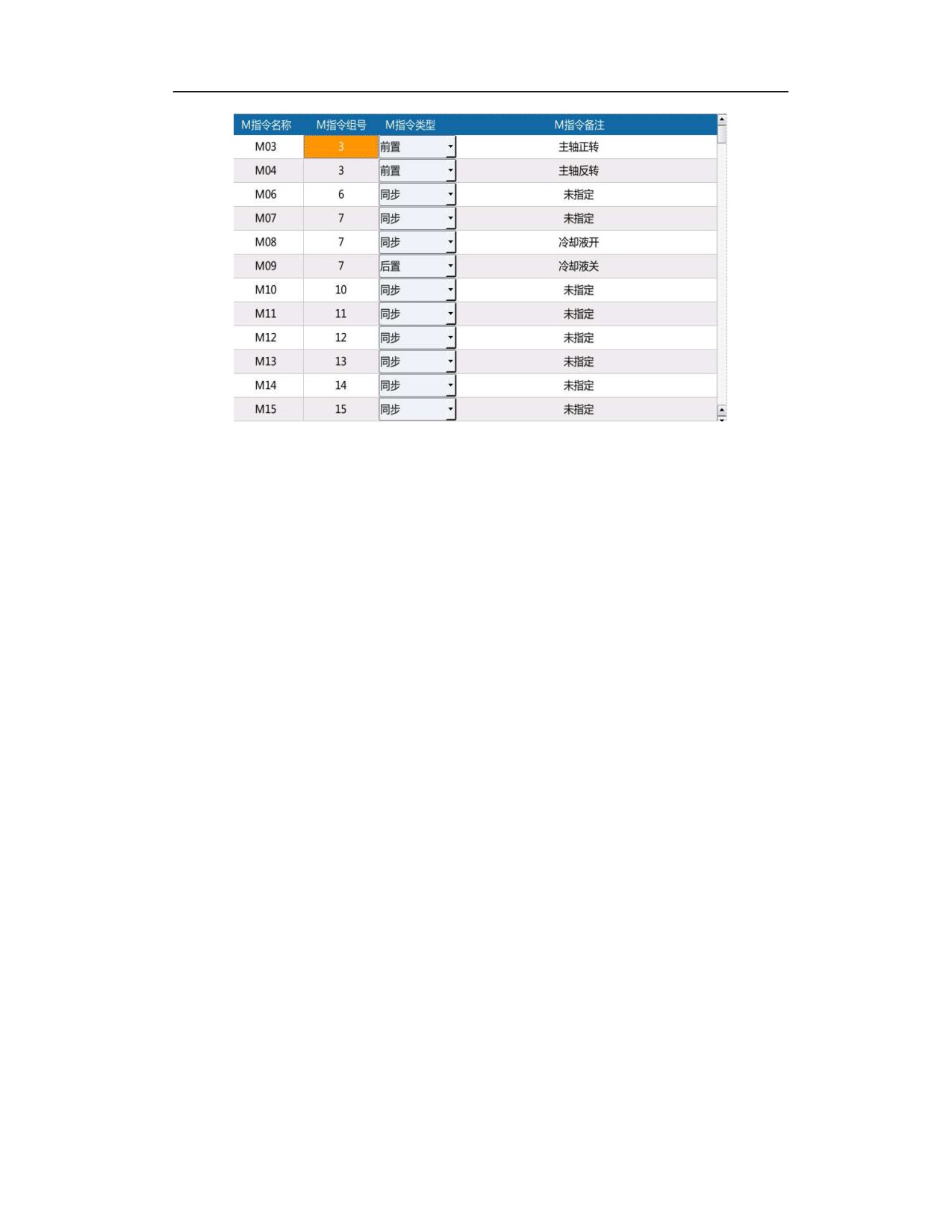
(Note 1) The activation modes of M codes M00, M01, M02, M05, M30, M92, and M93 that are
not displayed in the list are fixed and cannot be modified.
(Note 2) The M code that is set or defaulted to the post should not be specified together with the
traverse command. It is better to be specified in a line separately, otherwise errors of some M
codes may occur.
Multiple M command specification instructions
Usually only one M code is valid for a block. In this system, at most 4 M codes can be specified
in a block. When users need to specify multiple M codes in a block, please note the following:
(1) Up to 4 M codes can be specified in a block, and multiple M codes in the same group are
regarded as one.
(2) When multiple M codes of the same group are designated in a block, the last M code in the
block is effective.
(3) When multiple different groups of M codes are designated in a block, the M codes in the
block are all effective.
(4) M codes such as M00, M01, M02, M30, M99 cannot be specified together with other M
codes.
(5) M codes such as M00, M01, M02, M30, and M99 require to be specified in a separate line,
that is, the program line containing the above M codes can not only have one M code, and cannot
have other execution commands including G and T commands.
(6) The corresponding relationship between M codes and functions depends on the specific
settings of the machine tool manufacturer. See the machine tool manufacturer's manual for
details.
27
Note
Although multiple M codes can be specified in a block, due to the different specifications of
each machine tool and the different settings by each machine tool manufacturer, it is
recommended not to specify multiple M codes in a block at the same time, otherwise
unpredictable errors may occur.
4.1.1 Default Auxiliary Function of CNC
Function and Purpose
M00 Program dwell
When the CNC executes the M00 command, it will pause the execution of the current program
to facilitate the operator to perform operations such as tool and workpiece size measurement,
workpiece U-turn, manual speed change, etc.
During pause, the feed of the machine tool is held, and all the existing modal information
remains unchanged. User should press the CycleStart button on the operation panel for the
continued execution of subsequent program.
M00 is valid for the current program line, it is the post M function. Its post attribute is not
allowed to be modified.
M01 Optional stop
If user presses the Optional Stop button on the operation panel, when the CNC executes the M01
command, it will suspend the execution of the current program and the machine tool will be in
the feed hold state to facilitate the operator to perform the tool extension length and workpiece
size measurement, workpiece U-turn, manual speed change and other operations. During pause,
the feed of the machine tool stops, and all the existing modal information remains unchanged.
User should press the CycleStart button on the operation panel for the continued execution of
subsequent program.
If user does not activate the Optional Stop button on the operation panel, when the CNC executes
the M01 command, the program will not pause and continue to execute.
M01 is valid in the current program line, it is the post M function. Its post attribute is not allowed
to be modified.
M92 Program dwell (manual intervention)
When CNC executes M92, the program execution pauses and the machine is in feed hold state,
but the difference from M00 is that at this time user can manually intervene in each axis,
manually command its movement, and then switch to the Auto mode to continue the running of
28
the current program after pressing CycleStart button.
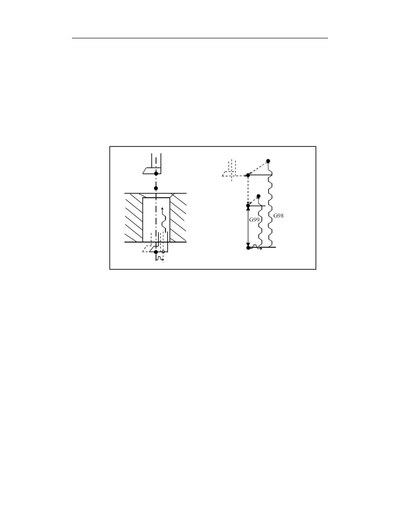
M92 can be used in the following occasions:
(1) In manual boring, when the boring tool is automatically processed to the bottom of the hole,
the machine tool stops running, and changes the working mode to "Jog". Through manual
operation, the tool can only retract after moving radially in the opposite direction of the tool
nose for a certain distance to avoid the wall of the workpiece hole. The general milling machine
can complete fine boring with this command without the need of spindle exact stop function.
Return
to
point B
Spindle CW
Initial point B
Reference point R
Return to
point B
Reference point R
Spindle CW
Hole bottom Z
Delay at hole bottom,
Hole bottom Z
spindle stop
(2) During manual measurement, when the user manually measures the tool or workpiece
through the dialogue interface, the CNC actually processes it as a manual measurement cycle,
and M92 is inserted in the appropriate place in the cycle to guide the user to complete the entire
measurement task. If the system executes M92 of the canned cycle, the program is paused. At
this time, the system waits for the user to switch to the "Jog" mode to command the measuring
axis to run to the measuring position, and then switches to the "auto" mode. User presses the
CycleStart button to continue the measurement cycle.
M93 Program dwell (manual intervention is disabled)
The M93 command is equivalent to the M00 command. Unlike M92, the user cannot perform
manual intervention when the program is paused with M93.
M02 End of program
M02 is in the last block of the main program. When the CNC executes the M02 command, the
spindle, feed, and coolant of the machine tool stop, and the machining ends.
If user needs to re-execute the program which has been finished its execution with M02, user
29
has to call the program again, or press the "rerun" key in the submenu of automatic processing,
and then presses the CycleStart button on the operation panel.
M02 is valid in the current program line. It is the post M function. Its pre and post attributes are
not allowed to be modified, and it must be specified in a separate line.
M30 Program ends and returns
The functions of M30 and M02 are basically the same, but the M30 command also has the
function of returning to the program head.
If user needs to re-execute the program which has been finished its execution with M30, just
press the CycleStart button on the operation panel again.
(Note 1) This command must be placed in a separate line to take effect.
M98/M99 Subprogram call
If the program contains a fixed sequence or frequently repeated pattern, such a sequence or
pattern can be stored as a subprogram in the memory to simplify the program.
(Note 1) The maximum number of subprogram calls (L) is 10,000 times.
(Note 2) A subprogram can be called from the main program.
(Note 3) A called program can also call another subprogram.
Structure of subprogram
%xxxx; Subprogram No.
……; Subprogram contents
M99; Subprogram returns
Subprogram call (M98)
M98 P__ L__
P__: Subprogram No. called (in Arabic numerals)
L__: The number of times the subprogram is called repeatedly
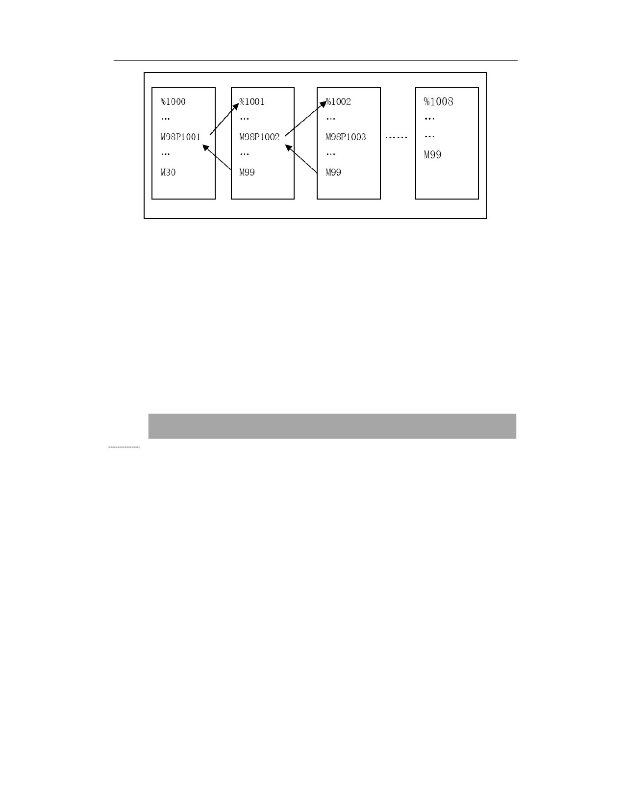
Nested call of subprogram
When the main program call a subprogram with M98, it can be regarded as a first-level of
subprogram call. The subprogram call can be nested up to 6 levels, as shown below:
30
(Note 1) When the main program calls a subprogram with M98, G80 must be added before M99
in the subprogram to ensure the correct operation of the program.
(Note 2) M98/M99 need to be used in a separate line (avoid being in the same line with other
commands).
Use M99 in the main program
If M99 is executed in the main program, the control returns to the beginning of the main program,
and the main program is executed from its beginning, and loops forever.
4.1.2 Auxiliary Function Set by PLC
Function and Purpose
M03/04/05 Spindle control
M03 Starts the clockwise rotation of spindle at the speed programmed (viewed from the positive
direction to the negative direction of Z axis).
M04 Starts the counterclockwise rotation of spindle at the speed programmed.
M05 Spindle stops
(Note 1) M03, M04, and M05 can mutually cancel each other.
(Note 2) The spindle can be switched from position mode to speed mode with M03/M04 instead
of G109.
31
M06 Tool change
M06 is used to call a tool which needs to be installed on the spindle of the machining center. When
this command is executed, the tool will be automatically installed on the spindle. For example:
M06 T01; the tool 01 will be installed on the spindle.
(Note 1) M06 is effective in the current program line.
(Note 2) M06 needs to be used in a separate line (avoid being in the same line with other
commands).
M07/08/09 Coolant control
M07 and M08 are to turn on the coolant pipeline (based on the definition of the machine tool
manufacturer).
M09 is to turn off the coolant pipe.
M64 Workpiece counting
M64 will accumulate the number of completed workpieces in the system processing statistics
M19/M20 Spindle orientation
M19 is to enable spindle orientation.
M20 is to disable spindle orientation
4.2
Table of M Command Function and Regular Status
Pre/Post/Synchronous
Function
Function is valid
remains valid
Code
Function
in the block it
until it is
Synchronous
Pre
Post
exists
canceled
#
○
M00
Program dwell
#
○
M01
Optional stop
#
○
M02
End of program
M03
Spindle rotation CW
○
○
32

M04
Spindle rotation CCW
○
○
M05
Spindle stop
#
○
M06
Tool change
○
○
M07
Coolant 2 ON
○
○
M08
Coolant 1 ON
○
○
M09
Coolant OFF
○
○
M10 to M18
Undefined
○
M19
Spindle orientation
○
○
○
M20
Spindle orientation cancel
Tool release (umbrella-type
○
M21
○
magazine)
Tool clamping (umbrella-
○
M22
○
type magazine)
Magazine forward
○
M23
○
(umbrella type magazine)
Magazine backward
○
M24
○
(umbrella type magazine)
Tool selection (umbrella-
○
M25
○
type magazine)
M26 to M29
Undefined
Program ends and returns
#
○
M30
to its head
M31 to M63
Undefined
○
○
M64
Workpiece counting
M65 to M91
Undefined
33
Program dwell (manual
M92
#
○
intervention)
Program dwell (manual
M93
#
○
intervention is not allowed)
M94 to M97
Undefined
○
○
M98
Subprogram call
Subprogram returns to
○
○
M99
main program
M100 to
Undefined
M999
“○”:The function is conventionally specified.
“#”: The function status is fixedly specified.
For the "undefined" codes, its function may be defined when the standard is revised in the future.
34
5 Spindle Function
5.1
Spindle Speed Setting
Function and Purpose
The spindle speed can be controlled by the number specified after the address S.
In addition to running in speed mode (rotating at a certain speed), the spindle can also operate in
position mode (switching to the rotary axis for interpolation calculation).
Through the M command controlled by the PLC, the S command is processed and terminated.
Example
%1234
G92X0Y0Z20;Establish coordinate system
G00 X0 Y0 Z2;Positioned above the hole
M03S2000;CW spindle rotation
G41 G01 X20 D01 F300;Establish tool radius compensation
G03X40R10;Start the circular cutting
G03 I-40 Z-10 L5;Mill the hole in spiral
G03 I-40;Smooth the hole bottom
G03X20R10;Exit the circular cutting
G40G01X0;Cancel tool radius compensation
G0Z20;Lift the tool
M05;Spindle stops
M30;End of program
35
5.2
Constant Linear Speed Cutting Control(G96/G97
(T)
Function and Purpose
This function is only applicable to CNC lathe system. It adjusts the spindle speed with the
movement of the tool nose position (constant linear speed cutting control), so that the speed of the
cutting point is always a constant speed (fixed cutting speed), which improves the uniformity of
the surface.
As the tool nose is moving to the workpiece origin, the spindle speed of the machine tool is getting
higher and higher until the machine specification limit is reached, which is very dangerous.
Therefore, please be sure to set to the maximum speed limit in the spindle speed limit setting
command (G46).
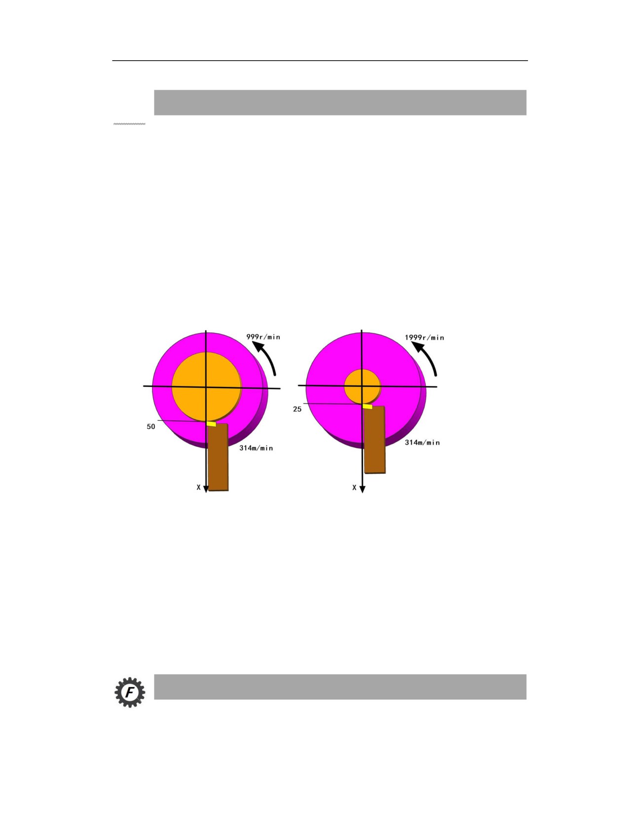
Constant linear speed control when the constant speed cutting control command G96 is set to
S314m/min.
Workpiece radius: 50mm (radius value) Workpiece radius: 25mm (radius value)
Because the linear speed is constant, the spindle speed is calculated as the tool nose position moves,
and it changes automatically.
In the above example, because the linear speed (314 m/min) is constant, the speed changes from
999 (r/min) to 1999 (r/min) as the radius of the workpiece changes (50mm → 25mm).
The relationship between linear speed and spindle speed
n=1000*V /πD
n——machine spindle speed r/min
V——Cutting linear speed of workpiece circumference m/min
D——Diameter of workpiece mm
Command Format
G96 P_ S_ ; To activate constant linear speed cutting control function of specified axis
36
G46 X_ P_; Spindle speed limit
G97 S_ ;
To disable constant linear speed cutting control function of specified axis
Parameter
Meaning
P
The control axis of the constant linear speed cutting control specified with the G96
command, the axis specified by P is determined by the system axis parameters. 1~3
respectively represent the X, Y, and Z axes;
The maximum speed limit of the spindle (r/min) when the G46 command specifies the
constant linear speed cutting control;
S
Specify the constant linear speed (mm/min or inch/min) with G96 command;
The designated spindle speed (r/min), after the constant linear speed cutting control is
canceled with G97 command,;
X
Minimum spindle speed limit (r/min) for constant linear speed;
Description
(1) The system only supports the X-axis to control spindle speed for constant linear speed cutting
control. The system has not yet opened the function of controlling the spindle speed with Y or Z
axis for constant linear speed cutting control;
(2) G96/G97 is a pair of modal commands, and they can be mutually canceled;
(3) The G46 command function is only valid when the constant linear speed cutting control
function is valid;
(4) To use the constant linear speed cutting control function, the spindle must be able to change
speed automatically. (E.g., servo spindle, PWM spindle);
(5) When performing the constant linear speed cutting control function, if the spindle speed is
greater than the maximum spindle speed, it will be clamped at the maximum spindle speed.
(6) The linear speed of spindle is specified with S command when the constant linear speed cutting
control is enabled.
(7) The constant linear speed calculation is always executed at the time of the cutting feed
command (such as G01).
(8) The constant linear speed cutting control cancel command (G97) is only available when the
constant linear speed cutting control command is enabled.
Note
1) G96 must be followed by G46 to limit the maximum and minimum spindle speed. When the
controlled axis of the constant linear speed cutting control approaches to the spindle center, the
spindle speed increases, and the allowable speed of the workpiece and chuck may be exceeded,
which may cause damage to the tool and machine tool, and even cause injury; while the controller
axis of the constant linear speed cutting control moves away from the spindle center, the spindle
37
speed decreases, which will be less than the actual machining speed required, resulting in the
inability to machine qualified parts. Therefore, G96 must be followed by G46 to limit the
maximum and minimum spindle speeds, and when user specifies the constant linear speed cutting
control during programming, pay attention to the distance between the controlled axis and the
spindle center.
2) When G96 is commanded, do not omit the linear speed command "S_". When the command is
omitted, the system will alarm.
5.3
Spindle Clamping Speed
Function and Purpose
The maximum and minimum spindle speeds are limited by G46 command. According to the
specifications of the workpiece, the chuck installed on the spindle, and the tool, the spindle speed
limit is set when the speed needs to be restricted, so that qualified products can be processed. It is
often used in conjunction with constant linear speed control G96/G97.
Command format
G46 X_ P_; Spindle speed limit
Parameter
Meaning
P
Max. spindle speed limit(r/min) when constant linear speed cutting control is
specified
X
Min. spindle speed limit (r/min) when constant linear speed cutting control is
specified
Description
The speed is limited only in the constant linear speed cutting control mode.
Note
Spindle clamping speed G46 is often used in conjunction with the constant linear speed cutting
control G96/G97. G96 must be followed by G46 to limit the maximum and minimum spindle
speed. When the controlled axis of the constant linear speed cutting control approaches to the
spindle center, the spindle speed increases, and the allowable speed of the workpiece and chuck
may be exceeded, which may cause damage to the tool and machine tool, and even cause injury;
while the controller axis of the constant linear speed cutting control moves away from the spindle
center, the spindle speed decreases, which will be less than the actual machining speed required,
resulting in the inability to machine qualified parts. Therefore, G96 must be followed by G46 to
limit the maximum and minimum spindle speeds, and when user specifies the constant linear speed
cutting control during programming, pay attention to the distance between the controlled axis and
38
the spindle center.
5.4
C/S-Axis Switching(CTOS/STOC)
Function and Purpose
In addition to running in speed mode (rotating at a certain speed), the spindle can also run in
position mode (switching to the rotary axis for interpolation calculation). At this time, the spindle
drive needs to support the speed mode/position mode switching function (ie C/ S-axis switching
function).
In some applications such as the rigid tapping function, the C/S-axis switching function is required.
Command format
STOC/G108 IP;
CTOS/G109 IP;
Parameter
Meaning
IP
IP can be A/B/C, the number after them indicates the spindle number in the channel, the
value ranges from 0 to 3;
When the IP is absent after STOC, the No. 0 spindle is changed to the C axis by default;
When the IP is absent after CTOS, the C axis is changed to to the No. 0 spindle by
default.
Explanation: 1) G108 B0 means to switch No. 0 spindle to B axis; G109 B0 means to switch B
axis back to No. 0 spindle. Generally, the G108 B0 function is used on the 5-axis machine tool;
the 3-axis milling machine generally only uses G108 (no IP is written afterwards), and the No. 0
spindle becomes the C axis by default.
Example
%0007; Rigid tapping test program, R is the program zero
G92 G17 Z0.000
G109
M03 S1000.000; CW spindle rotation
M05
G90 G0 Z1
G108; Switch speed mode to position mode for spindle
G98 G84 Z-20.000 R1 P500 F1.000; Perform rigid tapping
G109; Switch position mode to speed mode for spindle
G01 Z0.000
M30
Note: The current version of the system software G84 canned cycle already includes the C/S-axis
39
//////////////////////