HNC8 Series CNC Controller. Programming Manual (V2.4) - page 3

command must not be in the same line with the G command which causes the change of length
compensation vector, for example, it cannot run in the following blocks;
The block where G43/G44 is specified;
The block where H code is specified in the G43/G44 mode;
The block where G49 is specified in G43/G44 mode;
In the G43/G44 mode, the block where is vector is restored after the
compensation vector is temporarily cancelled by G28, G53, etc.
In addition, when the workpiece coordinate system is set by G92 command, the blocks before it
stop, and the tool length compensation amount selected by MDI cannot be changed.
10.3.2 Workpiece Coordinate System Selection G54~G59(G54.X)
Function and Purpose
The six standard workpiece coordinate systems preset in the system can be selected through the
six commands G54 to G59. The standard workpiece coordinate system zero is manually input
through the HMI interface.
Description
In the control system, G54 ~ G59 commands can be used to select the current workpiece
coordinate system among 6 preset workpiece coordinate systems. When there are many workpiece
sizes and there are relatively multiple different marking datums, the coordinate values of several
datum points in the machine coordinate system can be input into the system in advance through
MDI as the coordinate origin of G54 ~ G59, and the system will remember these points
automatically. Once one of the G54~G59 commands is executed, the origin of the workpiece
coordinate system is the current programmed origin, and the absolute coordinates in the
subsequent blocks are the values relative to the programmed origin.
G54 Workpiece coordinate system 1
G55 Workpiece coordinate system 2
G56 Workpiece coordinate system 3
G57 Workpiece coordinate system 4
G58 Workpiece coordinate system 5
G59 Workpiece coordinate system 6
Example
G54 G90 G00 X100 Y100 Z5; Position to X100 Y100 Z5 position in G54 coordinate system
G55;
Set G55 as the current coordinate system
G00X30Y30;
Move to the point X30Y30 in G55
G52X45Y15;
Establish a local coordinate system G52 in the current G55
80
coordinate system
G00G90X35Y20;
Move to the point X35Y20 in G52
G53X35Y35;
Move to the point X35Y35 in G53 (machine coordinate
system)
Note
1) The workpiece coordinate systems G54 to G59 are established after the power is turned on and
the reference point is returned.
2) G54 coordinate system is automatically selected when the power is turned on.
3) Even if the workpiece coordinate system is switched by G54 to G59 and G54.X, the tool radius
compensation of the designated axis will not be cancelled.
4) G54 to G59 and G54.X are modal commands.
10.3.3 Extended Workpiece Coordinate System Selection(G54.x)
Function and Purpose
In addition to the six workpiece coordinate systems specified by G54 to G59 for users to choose,
the milling system also provides the extended workpiece coordinate systems.
The system provides 60 extended workpiece coordinate systems for users to choose.
Command Format
G54.X; To select No. X extended workpiece coordinate system
Parameter
Meaning
X
The index number of the extended workpiece coordinate system, ranges
from 1 to 60, a total of 60.
Example
%1234
G54.18
G90 G00 X100 Y100 Z50; Position to X=100 Y=100 Z=50 in the 18th extension
coordinate system
M30
81
Note
Once the workpiece coordinate system is selected, it remains valid until it is selected by another
workpiece coordinate system
Select the standard workpiece coordinate system 1 (G54) when the power is turned on
G54.1 P1 additional workpiece coordinate system 1
G54.1 P2 additional workpiece coordinate system 2
┇
G54.1 P60 additional workpiece coordinate system 60
10.3.4 Workpiece Coordinate System Modification (G10)
Function and Purpose
Generally, the operator can modify the external workpiece origin offset or the workpiece origin
offset through the HMI interface to change the workpiece coordinate system. And with this
function, G10 command can be used to realize the above changes in the program. For details, see
"Chapter 13 Programmable Data Input"
Command Format
G10 L2 Pp IP_;
Parameter
Meaning
P=0
External workpiece zero offset value
P=1 to 6
Workpiece zero offset of workpiece coordinate systems 1 to 6
the workpiece origin offset of each axis in the absolute mode
IP
(G90); and the offset added to the workpiece zero set originally of
each axis in the incremental mode (G91), and the result of the
addition of the two is the new workpiece zero offset
Note
After the external workpiece zero offset is set, when the coordinate system is set with G92, the
coordinate system is not affected by the external workpiece zero offset. For example, when
"G92X100.0Y80.0" is commanded, the coordinate system where the current position of the tool
is X=100.0, Y=80.0 is specified.
82
10.4
Local Coordinate System Setting (G52)
Function and Purpose
When programming on the workpiece coordinate system, for convenience, user can create a sub-
workpiece-coordinate-system in the workpiece coordinate system. Such a sub-coordinate-system
is called a local coordinate system.
Command Format
G52 IP_; To set local coordinate system
G52 IP 0; To cancel coordinate system
Parameter
Meaning
IP
To specify the origin of local coordinate system
Description
1) Use G52 IP_; command to set the local coordinate system in all workpiece coordinate systems.
The IP value is the coordinate position in the workpiece coordinate system, and the position in
the workpiece coordinate system is the origin of the local coordinate system.
2) Once the local coordinate system is set, the movement command of the specified axis will be
the coordinates in the local coordinate system;
3) If user needs to cancel the local coordinate system or specify the coordinate value in the
workpiece coordinate system, coincide the origin of the local coordinate system with the origin
of the workpiece coordinate system.
83

Local coordinate system
G64: workpiece coordinate system
Local coordinate
system
G59: workpiece
coordinate system
Machine coordinate system
Origin of machine coordinate system
Reference point
Local coordinate system
84
Example
%1234
G55;Select G55, assuming that the coordinates of G55 in the machine tool coordinate
system are (10, 20)
G1 X10Y10F1000;Move to the machine coordinate system (20, 30)
G52 X30Y30;Establish a local coordinate system based on all workpiece coordinates, the
origin of the local coordinate system is (30, 30)
G1 X0Y0;Move to the origin of the local coordinate system (the current position of the
machine tool coordinate system is (40, 50))
G52 X0Y0;Cancel local coordinate system setting, and the system restores to G55
coordinate system
G1 X10Y10;Move to the machine coordinate system (20, 30)
M30
Note
1) When the manual reference point return of an axis is performed, the zero of the local coordinate
system of the axis is consistent with the zero of the workpiece coordinate system. The result is
the same as the result of the command G52 α0. (Α: axis returning to reference point)
2) The local coordinate system setting does not change the workpiece coordinate system and the
machine coordinate system.
3) When the workpiece coordinate system is set by G92 command, if the coordinate values of all
axes are not commanded, the local coordinate system of the axis for which the coordinate value
is not specified will not be cancelled, and will remain unchanged.
4) The offset in tool radius compensation is temporarily cleared with G52.
5) After the G52 block, the motion command is immediately specified in absolute mode
85
10.5
Coordinate Plane Selection(G17,G18,G19)
Function and Purpose
Coordinate plane selection G17/18/19 commands are used for the selection of the machining plane
in operations such as circular interpolation, tool radius compensation
(M), and rotation
transformation (M).
Description
G code
Plane
X
Y
Z
G17
XY plane
X axis or
Y axis or
Z axis or its
G18
ZX plane
its parallel
its parallel
parallel axis
G19
YZ plane
axis
axis
X, Y, Z are determined by the axis address appearing in the block where G17, G18 or G19
is specified;
When the axis address is omitted in the G17, G18 or G19 block, it is considered that the
basic 3-axis address is omitted;
When G17, G18, G19 are not specified in the block, the plane remains unchanged;
The movement command has nothing to do with the plane selection;
Parameter 000012 is used to set the tool length compensation axis;
Example
G17X_Y_
;XY plane
G18X_Z_
;XZ plane
G19Y_Z_
;YZ plane
X_Y_
;YZ plane is not changed
G17
;XY plane
G18
;XZ plane
G18Y_
;XZ plane, the movement on Y has no relationship with planes.
Note
G17, G18, and G19 are modal functions, which can be mutually cancelled. The default modal is
86
G17 after power-on. The movement command has nothing to do with plane selection. For example,
when G17 G01 Z10 is commanded, the Z axis still moves.
10.6
Machine Origin and 2nd, 3rd, 4th, and 5th Reference Points
Function and Purpose
There is a fixed mechanical point on the machine tool which can be used as the reference point
of the machine tool. This point is referred to as the machine origin, and its position is determined
by the dog of reference point return or the grating zero point. The machine origin is the reference
point of the basic mechanical coordinate system, and is a fixed mechanical point determined by
the reference point return. The reference point return function can accurately move the tool to the
set fixed position. The 1st, 2nd, 3rd, 4th, and 5th reference points are the positions preset with the
coordinate values in the parameters based on the origin of the basic machine coordinate system.
The first reference point in this system is usually set to 0. The 2nd, 3rd, 4th, and 5th reference
points are usually used for each buffer point and tool change point for the tool change action, so
as to realize the correct tool change action. Therefore, when the parameter values of the second,
third, fourth, and fifth reference points are set, please do not modify them at will, otherwise, the
tool cannot be changed, the tool change action error or dangerous situation may occur.
The values of the 2nd, 3rd, 4th, and 5th reference points are set by parameters. The values are set
based on the style of the magazine or the requirements of the machine tool manufacturer. Usually,
the setting is completed before the machine leaves the factory.
Take axis 0 as an example, through the coordinate values set in the coordinate axis parameters
(100017, 100021 to 100024), up to 5 reference points of the machine coordinate system can be
specified.
87
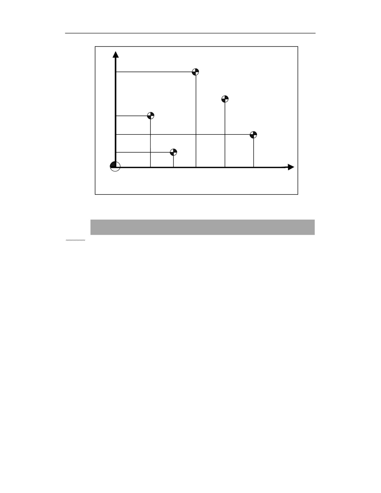
Reference point 2
Reference point 3
Reference point 1
Reference point 5
Reference point 4
Machine origin
10.7
Reference Point Return (G28/G29)
Function and Purpose
Through Automatic reference point return, the position of the machine tool can be corrected to
make the positions for machining or tool change consistent.
When returning to the reference point (G28) automatically, the tool quickly moves to the reference
point after passing the intermediate point, and the specified intermediate point is stored by CNC.
When returning from the reference point (G29), it will automatically move to the specified point
along the specified axis through the intermediate point.
The process of the reference point return and the return from reference point is shown in the figure
below:
88
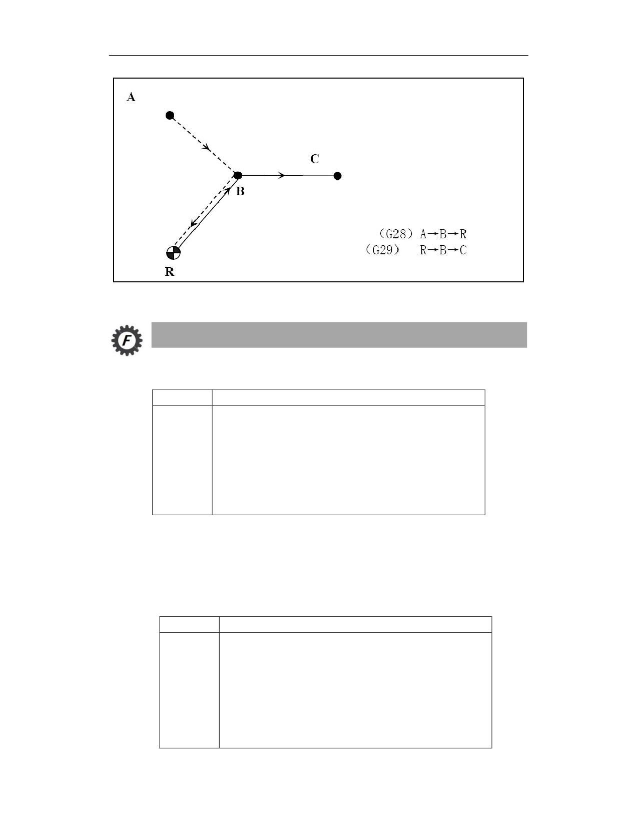
Starting point of reference point return
Target point of reference point return
Intermediate point
Automatic reference point return
Return from reference point
Reference point
(Note 1) The return from the reference point (G29) is only valid for the M series.
Command Format
G28 IP_;1st reference point return (automatic reference point return)
Parameter
Meaning
IP
In absolute mode (G90), to specify the absolute position of
the intermediate point.
In incremental mode (G91), to specify the distance between
the intermediate point and the starting point.
There is no need to calculate the specific amount of
movement between the intermediate point and the reference
point.
(Note 1) The coordinates of the IP command are the values in the workpiece coordinate system.
When the automatic reference point return command is executed, only the axis with the designated
intermediate point will move, and the axis without the designated intermediate point will not
move.
G29 IP_;Return from reference point
Parameter
Meaning
IP
In absolute mode (G90), to specify the position of the target
point.
In the incremental mode (G91), the intermediate point of G29
must be the intermediate point set by G28 last time, and G91
is executed for the coordinate value after G29 on the basis of
the intermediate point of G28.
89
(Note 1) The coordinates of the IP command are the values in the workpiece coordinate system,
and the intermediate point is the one previously specified with G28 and G30.
Description
Parameter setting
G29 related parameters are as follows (only the channel 0 parameters are listed)
Parameter
Description
040112
G28 intermediate point takes effect one time
040112:This parameter is to set whether the G28 intermediate point takes effect one time or
multiple times in the subsequent machining codes. If it takes effect multiple times, then the G28
intermediate point can be returned with G29 multiple times; if it takes effect one time, then it only
works on the first G29 after the G28.
0:G28 intermediate point takes effect one time.
1:G28 intermediate point takes effect multiple times.
Example
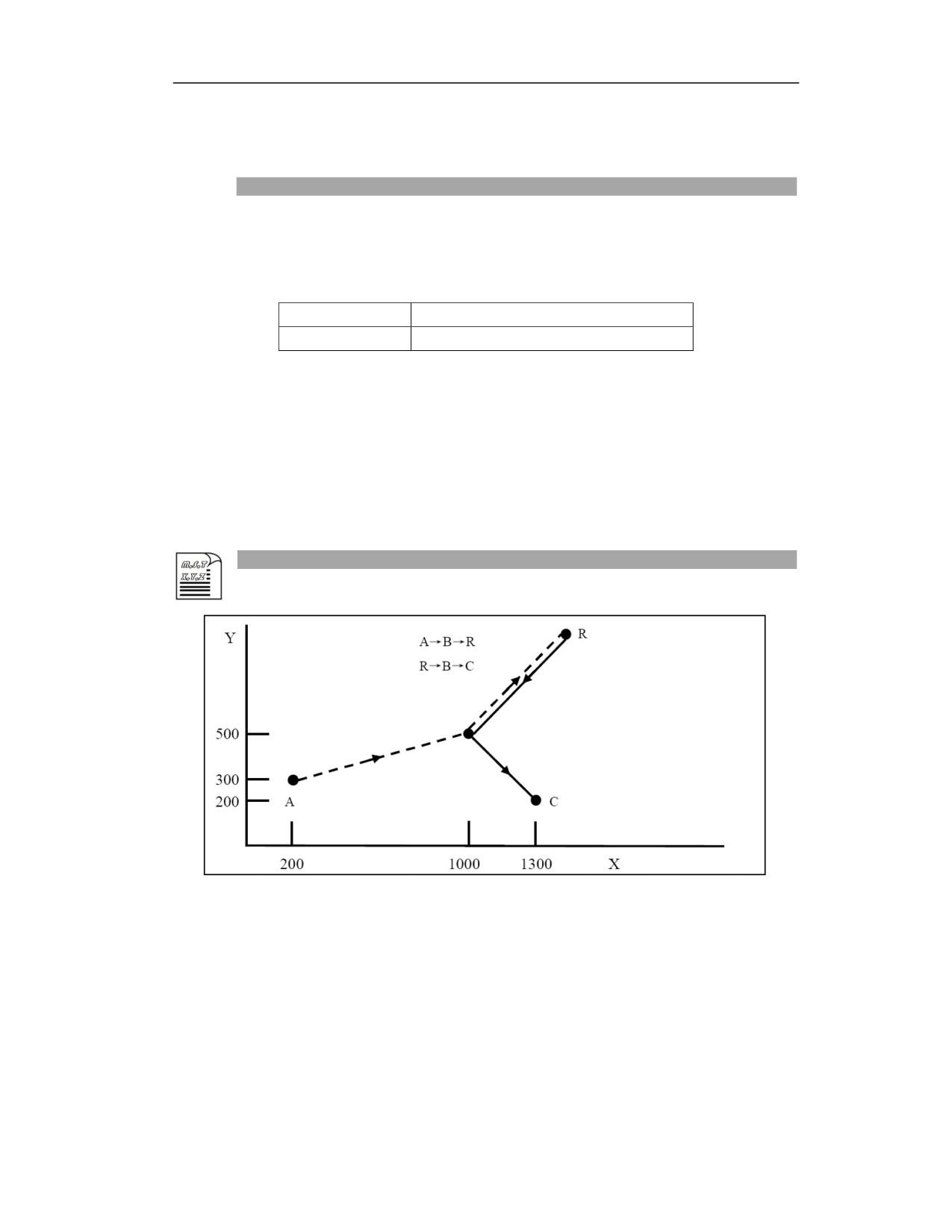
Reference point
B Intermediate
point
Starting point of
Target point of reference
reference
point
point return
return
G54
G00 X200Y300
G28 G90 X1000.0 Y500.0; The program from A to B. After passing the intermediate point
B, move to the reference point R
T6M06;Change tool at the reference point
G29 X1300.0 Y200.0;From the reference point R through the middle point B, move to the
C specified by G29
M30;Program ends
90
10.8
2nd, 3rd, 4th,5th Reference Point Return (G30)
Function and Purpose
With G30 P2 (P3 P4 P5) command, the 2nd, 3rd, 4th or 5th reference points (origin) return can
be performed.
Command Format
Return to the 2nd, 3rd, 4th or 5th reference points
G30 P2 IP_
; Return to the 2nd reference point (P2 can be omitted)
G30 P3 IP_
; Return to the 3rd reference point
G30 P4 IP_
; Return to the 4th reference point
G30 P5 IP_
; Return to the 5th reference point
Parameter
Meaning
In absolute mode (G90), to specify the absolute position of intermediate point;
IP
In incremental mode, to specify the distance from intermediate point to the
starting point.
There is no need to calculate the specific amount of movement between the
intermediate point and the reference point.
Description
Parameter setting:
Accurate reference point return enable
For the reference point return with G28, G30, the reference point return mode can be set to the
accurate return by parameters. In this mode, the zero pulse position is required to be found when
the reference point return is performed with G28, G30. The reference point return with G28 and
G30 is of the normal mode by default, and the zero pulse doesn’t need to be found, with the related
parameter set to 0. When it is necessary to return to the reference point with high accuracy, please
adopt the accurate reference point return and set the corresponding parameter to 1.
The relevant parameters of accurate reference point return are as follows (only the parameters in
channel 0 are listed):
Parameter
Description
040110
G28 Z pulse search Enable
040111
G28/G30 rapid traverse positioning selection
040110: This parameter is to set whether to search for Z pulse when reference point return is
91
performed with G28. G28 Z Pulse Search Enable is only for incremental motors. For absolute
motors, this parameter must be set to 0; for incremental motors, it can be set to 0 or 1.
0: search Z pulse.
1: not search Z pulse.
040111: This parameter is to set whether G28/G30 returns to the machine zero at the G00 rapid
traverse speed after moving to the machine reference point at the speed of G01.
0: Return to the machine zero at the speed of G01.
1: Return to the machine zero at the speed of G00.
Note
1) Tool length compensation and tool radius compensation cannot be canceled with G28/G29/G30.
2) When G28/G30 is executed, the tool completes the cancellation of tool radius compensation
during the process from the starting point to the intermediate point; during the process from the
intermediate point to the reference point, there is no tool radius compensation. When G29 is
executed, there is no tool radius compensation during the process from the reference point to the
intermediate point; the tool radius compensation is restored during the process from the
intermediate point to the target point.
3) The intermediate point specified by G28/G30 in the tool length compensation will be
cumulatively calculated with the length compensation, and the reference point to be returned
finally will not be cumulatively calculated with the length compensation. Whether the tool length
compensation will be restored after G28/G30 is executed is determined by NC parameter 000014.
The NC parameter 000014 is as follows:
Parameter
Description
000014
Whether to restore tool length compensation after G53/G28
This parameter is to set whether to automatically restore the tool length compensation function
after G53 command is executed.
0: After executing G53 command, the tool length compensation function is not restored
automatically.
1: After executing G53 command, the tool length compensation function is
automatically restored.
Note: G30 is the same as G28.
4) Whether the target point specified by G29 in the tool length compensation and the intermediate
point stored by G28 or G30 will be cumulatively calculated with the length compensation is
related to whether the NC parameter 000014 and G28/G30 commands are before or after G43.
The parameter is set to 0. When the G28 command is before G43, the intermediate point and
92
target point of G29 operation will accumulate with the tool length compensation;
The parameter is set to 1. Whether the G28 command is before or after G43, the intermediate
point and target point of G29 operation will be accumulated with tool length compensation;
5) When G28, G30, and G29 are executed, all axes move to the reference point or the intermediate
point at the G00 rapid traverse speed or G01 speed, and the speed can be controlled by the rapid
traverse override switch or the feed override switch.
6) During reference point return with G28/G30, first move to the intermediate point at the speed
of G01, and then return to the reference point at the speed of G0. The speed of returning to the
reference point can be set by channel parameter 040111 (take channel 0 as an example).
7) During the return from the reference point with G29, first move to the intermediate point at the
speed of G0, and then to the target point at the speed of G01.
8) G29 should be executed after G28 and G30 are executed, otherwise the execution may be
abnormal if there is no intermediate point stored.
93

11 Interpolation Function
11.1
Positioning (G00)
Function and Purpose
With this command, the machine tool can quickly and accurately move to the target position, and
its moving trajectory can be set by parameters as linear or non-linear path.
Command Format
G00 X__Y__Z__α__ ; (α is the auxiliary axis)
Parameter
Meaning
Represent the coordinate value. It is expressed as an absolute position or
X, Y, Z, α
an incremental position with the G90/G91 state.
Description
(1) G00 is a modal command, which is the 01 group command in the G command code. G00 can
be abbreviated as G0 in the programming.
(2) After G00 is specified, it will remain valid until it is replaced by the same group of G codes
(i.e. G01, G02, G03, G32 in group 01), and then only the coordinate address needs to be
commanded.
(3) With parameter 000013 [G00 Interpolation Enable], two tool paths can be specified:
a) Non-linear interpolation rapid traverse positioning:
When the parameter is set to 0, the tool will move at the rapid traverse speed of each axis
from the current position to the positioning target specified in the block.
b) Linear interpolation rapid traverse positioning:
When the parameter is set to 1, the tool path is the same as the linear interpolation G01. The
tool path is the shortest path between the start point and the end point. The positioning speed
is automatically calculated within the range where the specified axis speed does not exceed
its rapid traverse feedrate to ensure the shortest allocated time.
94
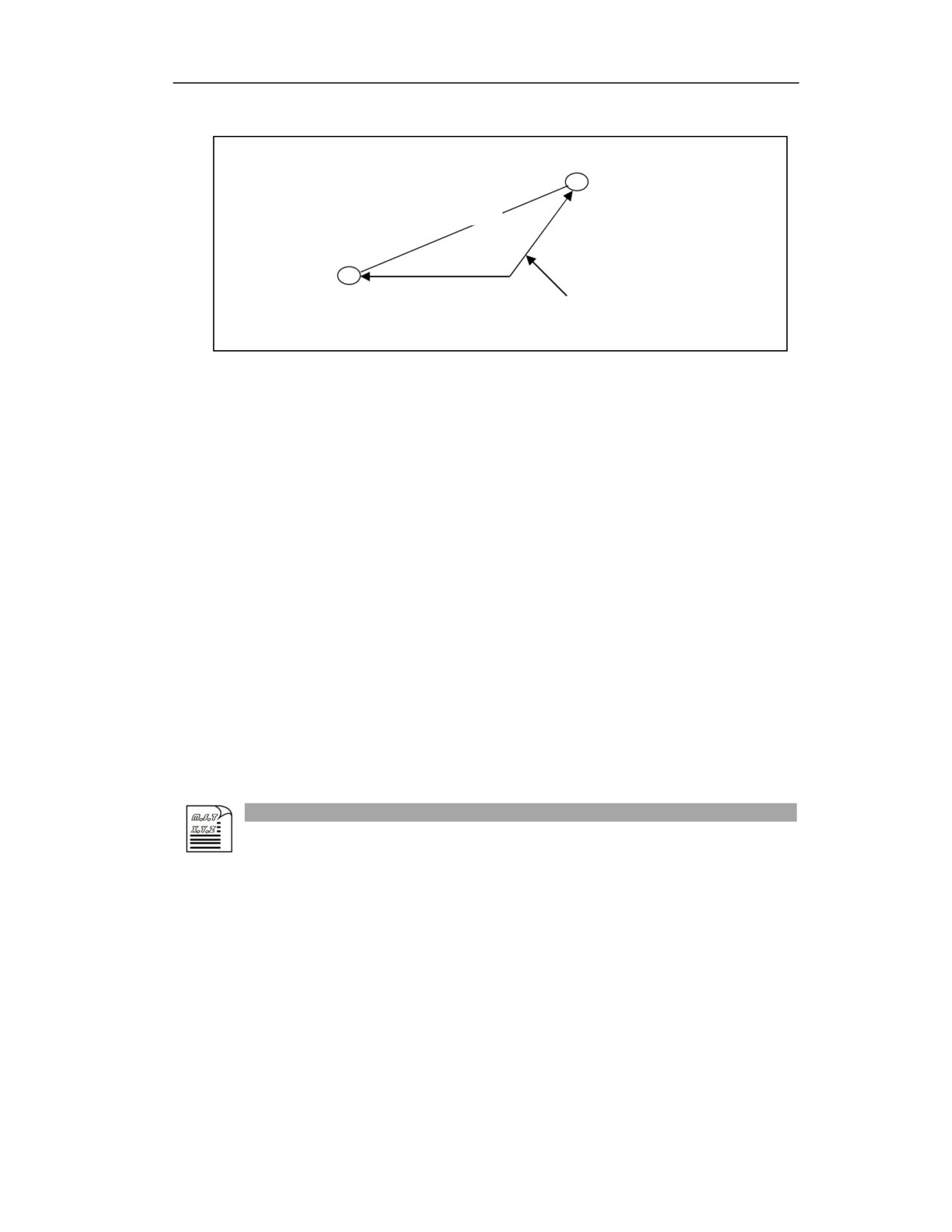
Starting point
Linear interpolation positioning
End point
Non-linear interpolation
positioning
(4) The maximum rapid traverse speed in G00 command is set by the axis parameter [Maximum
rapid traverse speed] (100034 for axis 0),(101034 for axis 1),(102034 for axis 2), etc., respectively
corresponding to each axis setting, and cannot be specified by F .
(Note 1) The parameter value of the maximum rapid traverse speed cannot be greater than the
maximum motor speed * screw pitch.
(5) When the program is running, the rapid traverse speed of G00 is controlled by the rapid
traverse speed override on the system operation panel.
(6) G00 is generally used for rapid traverse positioning before processing or rapid traverse
retraction after processing. In the positioning mode enabled by G00, the tool accelerates to a
predetermined speed at the starting point of the block, and decelerates near the target position.The
next block is executed after the tool is in the position.
(7) The allowable error of G00 rapid positioning is set by the system parameters (100060 for axis
0), (101060 for axis 1), (102060 for axis 2), etc. (the system parameter 010166 Maximum Time
for Exact Stop Check sets the maximum time to check the positioning tolerance of the coordinate
axis after reaching a certain point with the rapid traverse positioning (G00))
Example
Example 1: As shown in the figure below, programming with G00: the tool is required to move
from point A to point B in rapid traverse positioning.
95
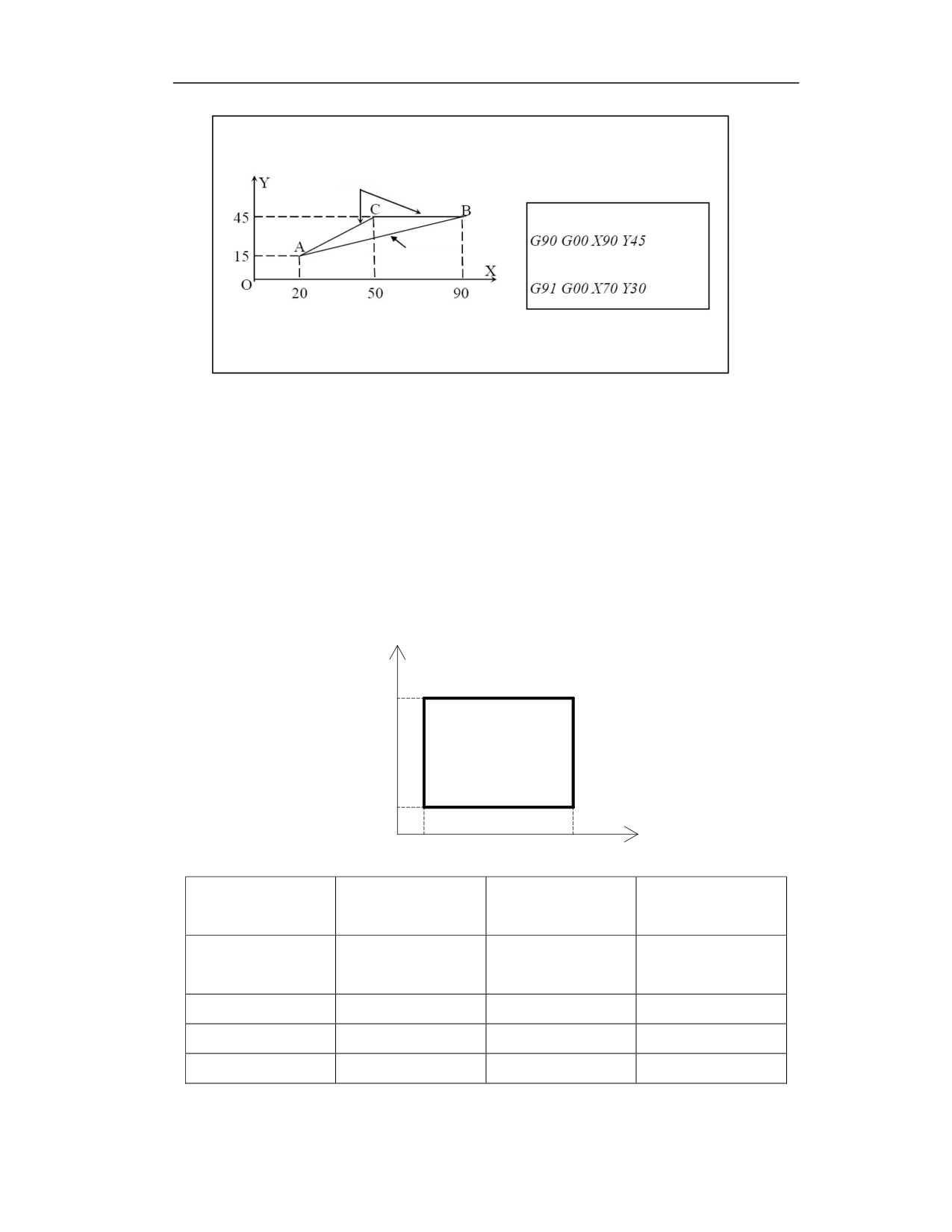
Actual path 1
Rapid
traverse
positioning from A to B
Absolute programming
Actual path 2
Incremental programming
(1)In the non-linear interpolation mode, when the rapid traverse speeds on X axis and Y axis
are the same, the rapid traverse positioning path from point A to point B is A—C—B;
(2)In the linear interpolation mode, when the rapid travers speeds on X axis and Y axis are the
same, the rapid traverse positioning path from point A to point B is A-B;
Example 2: As shown in the figure below, use G00 to program, a→b→c→d (starting point is at
origin X0, Y0).
Y
b
c
55
10
a
d
X
0
10
60
Machining path
Absolute
Incremental
Programmed
programming
programming
position
Rapid traverse
G90G00X10Y10
G91G00X10Y10
(X10、Y10)
positioning to a point
a→b
Y55
Y45
(X10、Y55)
b→c
X60
X50
(X60、Y55)
c→d
Y10
Y-45
(X60、Y10)
96
Note
(1) The rapid traverse speed can be corrected by the rapid traverse override knob on the panel.
(2) There is no value after the G command, and the system alarms "Syntax-Illegal symbol".
11.2
Unidirectional Positioning (G60)
Function and Purpose
This function enables each positioning movement of the machine tool to be realized in one
direction, by which the backlash of the machine tool can be eliminated and precise positioning
can be achieved.
Command Format
G60 X__Y__Z__α__ ;(α is the auxiliary axis)
Parameter
Meaning
The coordinate value. With the mode of G90 or G91, it is expressed as an
X,Y,Z,α
absolute position or an incremental position
Description
(1) G60 is a non-modal command. It is the 00 group command in the G command code, and is
valid only for the current line.
(2) When the system runs the G60 command, it is executed at the G00 rapid traverse speed.
(3) When executing G60 command, the offset amount and direction are set through the following
parameters. The positive and negative values determine the offset direction.
1st axis
Parm100030
G60 offset value vector of the first axis
2nd axis
Parm101030
G60 offset value vector of the second axis
3rd axis
Parm102030
G60 offset value vector of the third axis
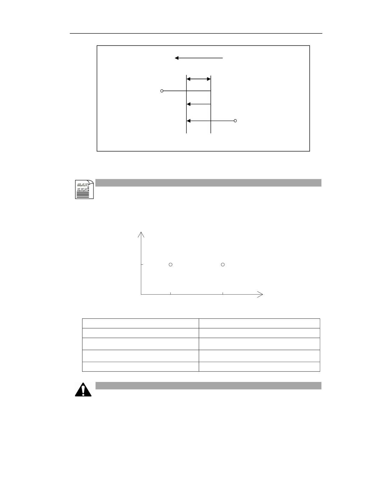
(4) In order to eliminate the influence of backlash, the positioning in one direction of the axis can
be commanded. As shown in the figure below, when the movement direction is consistent with
the positioning direction, the positioning is performed in a conventional way; when the movement
direction is inconsistent with the positioning direction, first move an additional offset along the
movement direction, and then move an offset distance along the positioning direction, finally
reach the end of the positioning.
97
Positioning direction
Offset
Start
Starting point
End point
Example
Use unidirectional positioning from A→B (parameter 100030 value is -10)
Y
Starting point
End point
A
B
30
X
0
30
70
Programming commands
Commanded coordinates
N1 G54
N2 G0X30Y30
N2
(X30、Y30)
N3 G60X70
N3
(X80、Y30)→(X70、Y30)
N4 M30
Note
1) Even if the tool movement distance is zero, unidirectional positioning is performed;
2) The set overtravel in unidirectional positioning should be greater than the backlash of the
corresponding axis, otherwise the backlash cannot be completely eliminated during unidirectional
positioning
98
11.3
Linear Interpolation (G01)
Function and Purpose
This command uses the combination of coordinates and feedrate commands to move
(interpolation) the tool linearly from the current point to the target point specified by the
coordinate address at the speed specified in the address F. At this time, the feedrate specified by
address F is always the linear speed in the direction of tool center movement.
Command Format
G01 X__Y__Z__α__F__ ;(α is the auxiliary axis)
Parameter
Meaning
The coordinate value. With the mode of G90 or G91, it is expressed as an
X, Y, Z, α
absolute position or an incremental position
F
Feedrate(mm/min or °/min)
Description
(1) G01 is a modal command, which is the 01 group command in the G command code, and can
be canceled by G00, G02, G03 and G32. G01 can be abbreviated as G1 in the programming.
(2) With the G01 command, the tool moves linearly from the current position to the end point
specified in the block at the synthetic feedrate specified by F in the simultaneous-axis mode.
(3) The feedrate specified by F is valid until the new value is designated. Therefore, it does not
need to be specified in every block.
(4) The maximum processing speed of G01 is set by the system axis parameter [maximum
processing speed] (100035 for axis 0),(101035 for axis 1),(102035 for axis 2), etc., respectively
corresponding to each axis. When the programmed F feedrate is greater than the maximum
processing speed set by the axis parameter, the system executes at the maximum processing speed
set by the axis parameter.
(Note 1) The maximum processing speed set cannot be greater than the maximum motor
speed * screw pitch
(5) When the program is running, the G01 processing speed is controlled by the speed override
on the operation panel of the system
(6) When F feedrate is not specified after G01 command, and the programming is in G94 feed per
minute, the system executes at the feedrate set by parameter 040030 "Default feedrate in
channel(mm/min)"; When the programming is in G95 feed per revolution, the system executes at
the feedrate set by parameter 040044 " Default feedrate in channel (mm/r)".
99
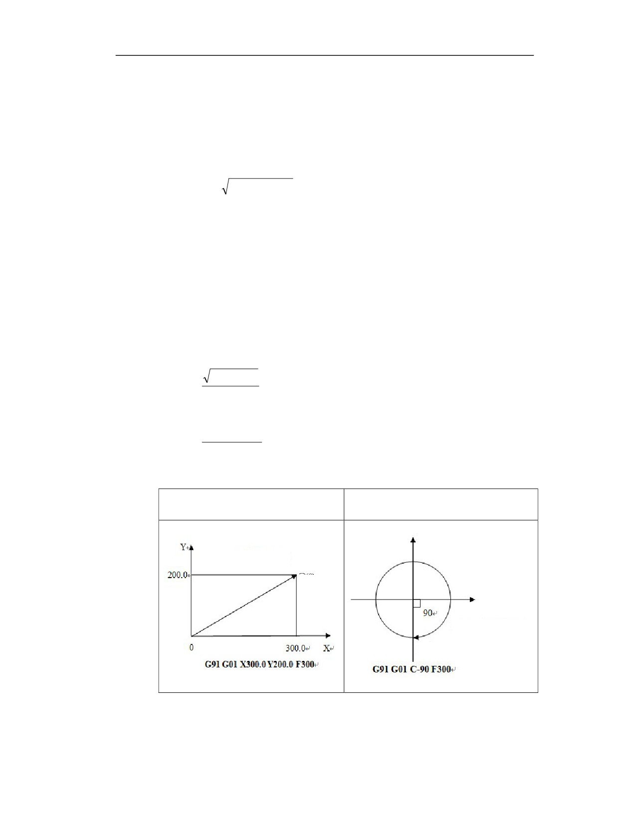
(7) The speed along each axis in each direction is as follows:
G91 G01 Xα Yβ ZγFf;
Speed along X axis Fα=α×f/L;
Speed along Y axis Fβ=β×f/L;
Speed along Z axis Fγ=γ×f/L;
2
2
2
L
For the rotary axis, the feedrate is specified by the linear speed.
(8) When the linear axis α (such as X, unit mm) and rotary axis β (such as C, unit deg) perform
the linear interpolation, the tangent speed in the Cartesian coordinate system of α and β is the
specified F (mm/min) speed. The speed on β is obtained by converting the required time to
deg/min using the above formula.
For example, G91 G01 X20.0 C40.0 F300.0;
Assume that the 40.0 deg of the C axis in metric is 40 mm.
The allocated time is:
20
2
402
≈0.14907min
300
The speed on C axis is:
40 deg
≈268.3deg/min
0.14907 min
(9) The trajectory in linear interpolation and rotary interpolation is as follows:
Linear interpolation
Rotary interpolation
Feedrate 300mm/min
End point
Start point
Feedrate
300
degrees/min
Start point
End point
10
Example
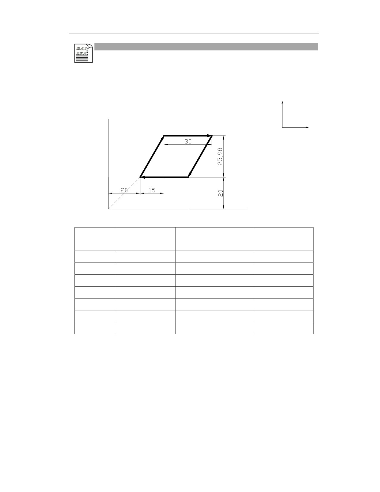
Perform the cutting on P1→P2→P3→P4 at a feedrate of 600mm/min; P0→P1 is the rapid
traverse positioning
Y
X
P2
P3
P1
P4
P0
Processing
Absolute
Incremental programming
Commanded position
path
programming
Positioning
G54G0X0Y0
G54G0X0Y0
(X0、Y0)
P0→P1
X20Y20
G91X20Y20
(X20、Y20)
P1→P2
G1X35Y45.98F600
G1X15Y25.8F600
(X35、Y45.98)
P2→P3
X65
X30
(X65、Y45.98)
P3→P4
X50Y20
X-15Y-25.98
(X50、Y20)
P4→P1
X20
X-30
(X20、Y20)
Program ends
M30
M30
10
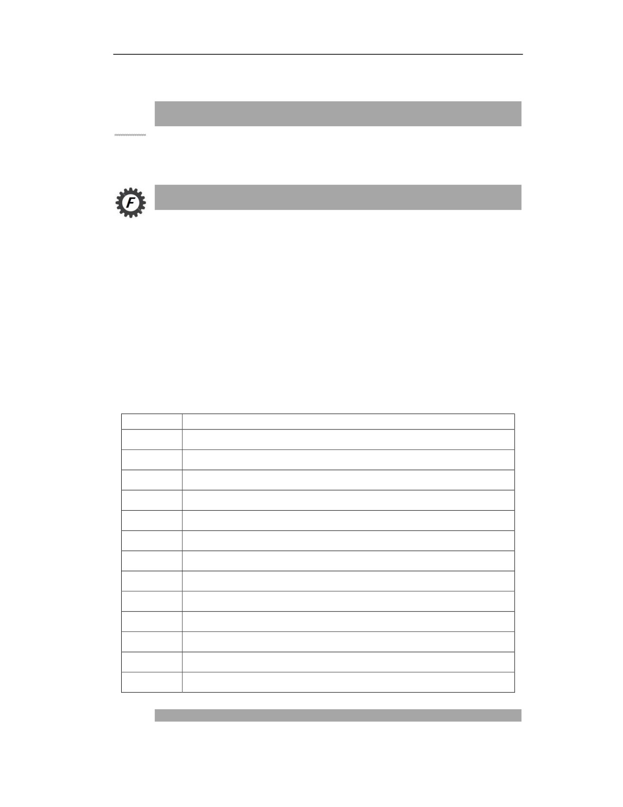
11.4
Circular Interpolation(G02/G03)
Function and Purpose
With this command, the tool moves to the end point in the specified plane (G17, G18, G19) along
the specified circular direction.
Command Format
G02
I
_
J
_
G17
X
_
Y
F
_
Circular interpolation in XY plane
G03
R
_
G02
I
_
K
_
G18
X
_
Z
F
_
Circular interpolation in ZX plane
G03
R_
G02
J
_
K
_
G19
Y
_
Z
F
_
Circular interpolation in YZ plane
G03
R_
Parameter
Meaning
G02
Circular interpolation CW
G03
Circular interpolation CCW
G17
Circular interpolation in XY plane
G18
Circular interpolation in ZX plane
G19
Circular interpolation in YZ plane
X
Movement amount on X axis of circular interpolation or X coordinate of circular end
Y
Movement amount on Y axis of circular interpolation or Y coordinate of circular end
Z
Movement amount on Z axis of circular interpolation or Z coordinate of circular end
R
Radius (with sign, "+" minor arc, "-" major arc)
I
The distance from the circular starting point to the circular center on X (with sign)
J
The distance from the circular starting point to the circular center on Y (with sign)
K
The distance from the circular starting point to the circular center on Z (with sign)
F
Feedrate, modal
Description
10
1)Circular command description
G02/G03 are modal commands, which are the 01 group commands in G codes. G02/G03 can be
abbreviated as G2/G3 during programming.
2)Circular interpolation direction
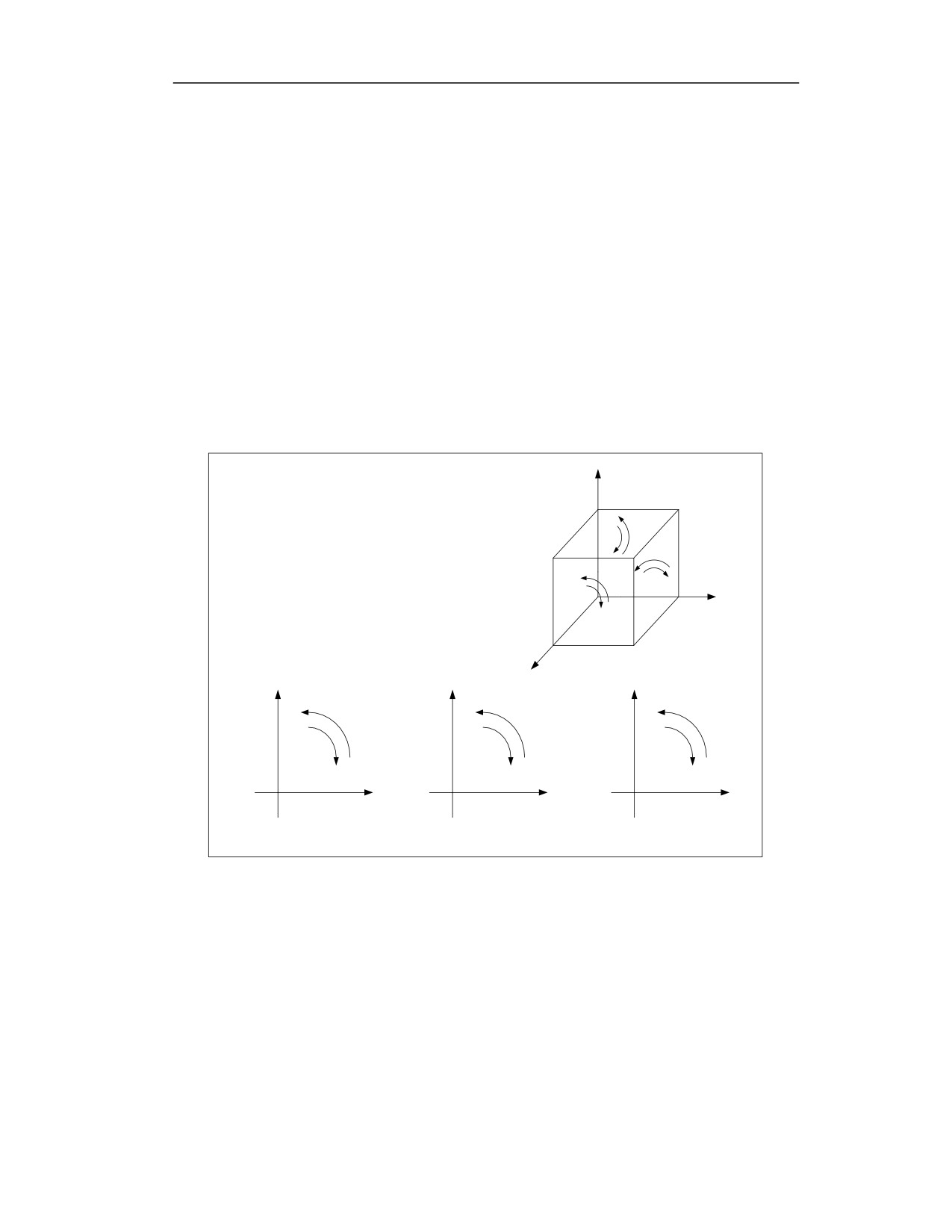
The definition of the circular interpolation direction in each plane: In the Cartesian coordinate
system, viewed from the positive to negative direction of the third axis, when the circular motion
direction is consistent with the clockwise direction, it is the clockwise circular interpolation
direction; when the circular motion direction is the same as the counterclockwise direction, it is
the counterclockwise interpolation direction.
The third axis is Z axis in XY plane, Y axis in ZX plane, and X axis in YZ plane. The definitions
of directions are as follows:
Z
G02
G03
G03
G03
G02
G02
X
Y
Y
X
Z
G03
G03
G03
G02
G02
G02
X
Z
Y
G17(X-Y)
plane
G18(Z-X)
plane
G19(Y-Z)
plane
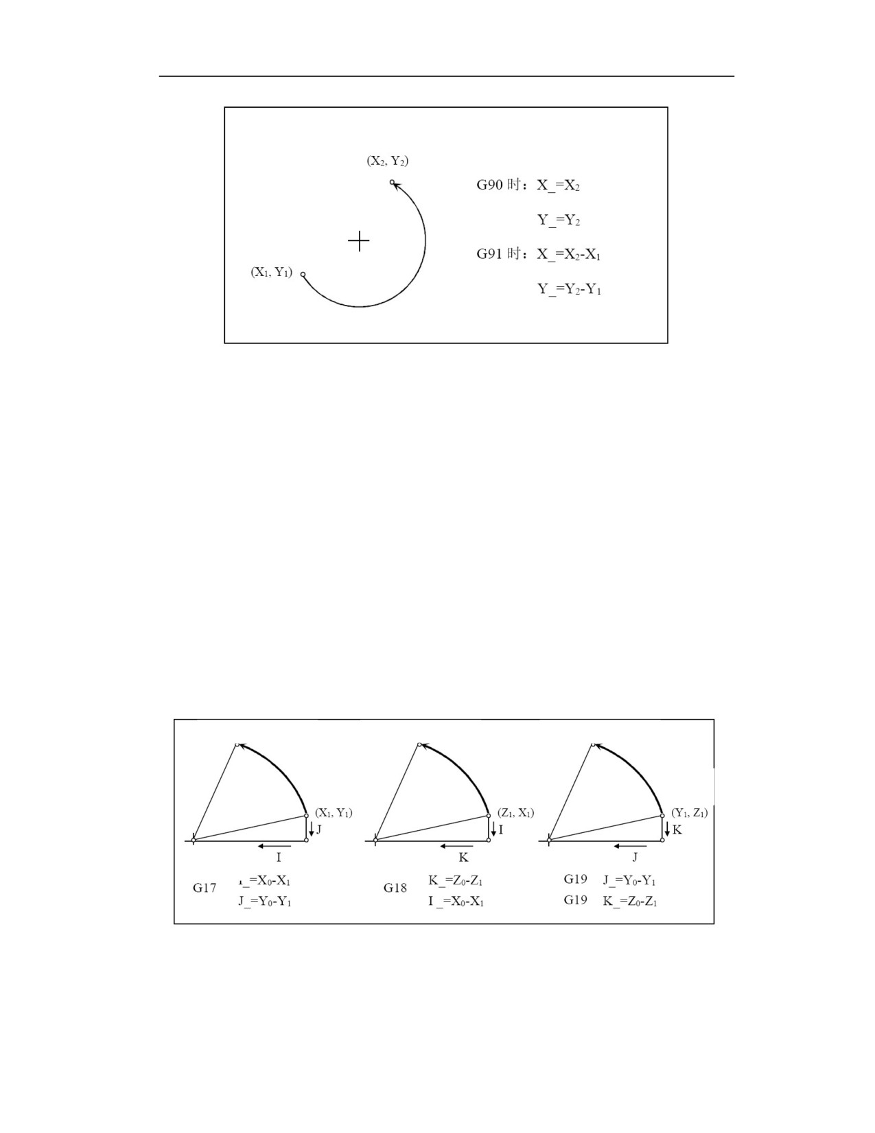
3)Circular end point
The circular end is specified with position command (X, Y, Z)
In absolute mode (G90),(X,Y,Z)specifies the absolute position of circular end; in incremental
mode (G91), (X,Y,Z) specified the distance from the circular starting point to the circular
end point.
10
End point
End point of arc
Starting point
4)UVW incremental programming
In addition to XYZ, UVW can also be used to specify the circular end point.
For the turning system (T series), when the channel parameter [UVW incremental programming
enable] (040033) is set to 1, UVW can be used instead of XYZ to represent the movement amount
(increment) in G02/G03 on the XYZ-axis, and user can also use XYZ and UVW for programming
simultaneously. (The premise is that the UVW axes are not designated as the traverse axes)
5)Circular center with IJK
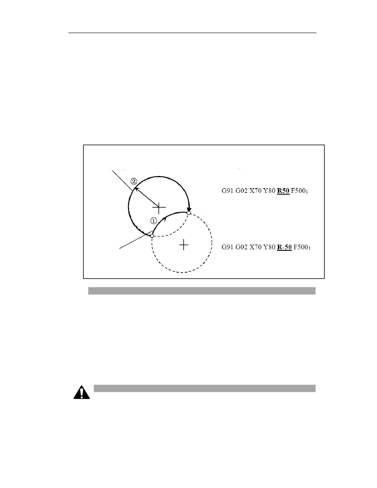
Command (I, J, K) is used to specify the position of the circular center.
The value specified by (I, J, K) is the vector component viewed from the starting point to the
circular center, and whether in G90 or G91 it is always an incremental value.
The sign of the values specified with (I, J, K) determines the direction.
The representation of the circular center is shown in the figure below
End point (X2,Y2)
End point (Z2,X2)
End point (Y2,X2)
Starting
Starting point
Starting point
point
Circle center
Circle center
Circle center (Y0, Z0)
(X0, Y0)
(Z0, X0)
6)Full circle programming
If all the position commands (X, Y, Z) are omitted during programming, it means that the start
point and the end point coincide. At this time, a full circle is designated with (I, J, K) programming.
10
If specified with R, it becomes an arc of 0 degrees, and the system alarms.
7)Semicircle programming
The circular center can be specified by the above-mentioned (I, J, K) as well as the radius. There
are two cases for the radius being used to specify the center of the circle.
a) An arc with a center angle less than 180°;
b) An arc with a center angle greater than 180°;
Therefore, user should specify clearly what arc is for the programming, which is determined by
the sign of the radius R. As shown below,
Arc of the center angle larger than 180°
Arc
1
End
point
Arc
2
Starting
point
Arc of the center angle smaller
than 180°
Parameter setting
Parameters of circular interpolation
If the difference between the radiuses of circular starting point and end point is greater than the
setting value of [Circular Interpolation Contour Error] (000010), or the ratio of the difference
between the radiuses of circular starting point and end point to actual radius exceeds the setting
value of [Allowable deviation of circular radius] (000011), the system will alarm.
When parameter 010098 [Whether to switch to G01 when G02/G03 is by default] is set to 1, and
the radius is not specified in the G02/G03 command, the block will be executed with G01.
Note
1)If I, J, K and R are specified at the same time in the non-full-cirlce circular interpolation, the
arc specified with R is valid.
2)If the axis not in the plane is specified, the alarm will be issued.
10
3)For the semicircle or the acr with center angle close to 180 degrees, specifying the center
position with R will result in the circular center calculation error due to the rounding error in
the programmed position. In this case, I, J, K should be used to specify the circular center.
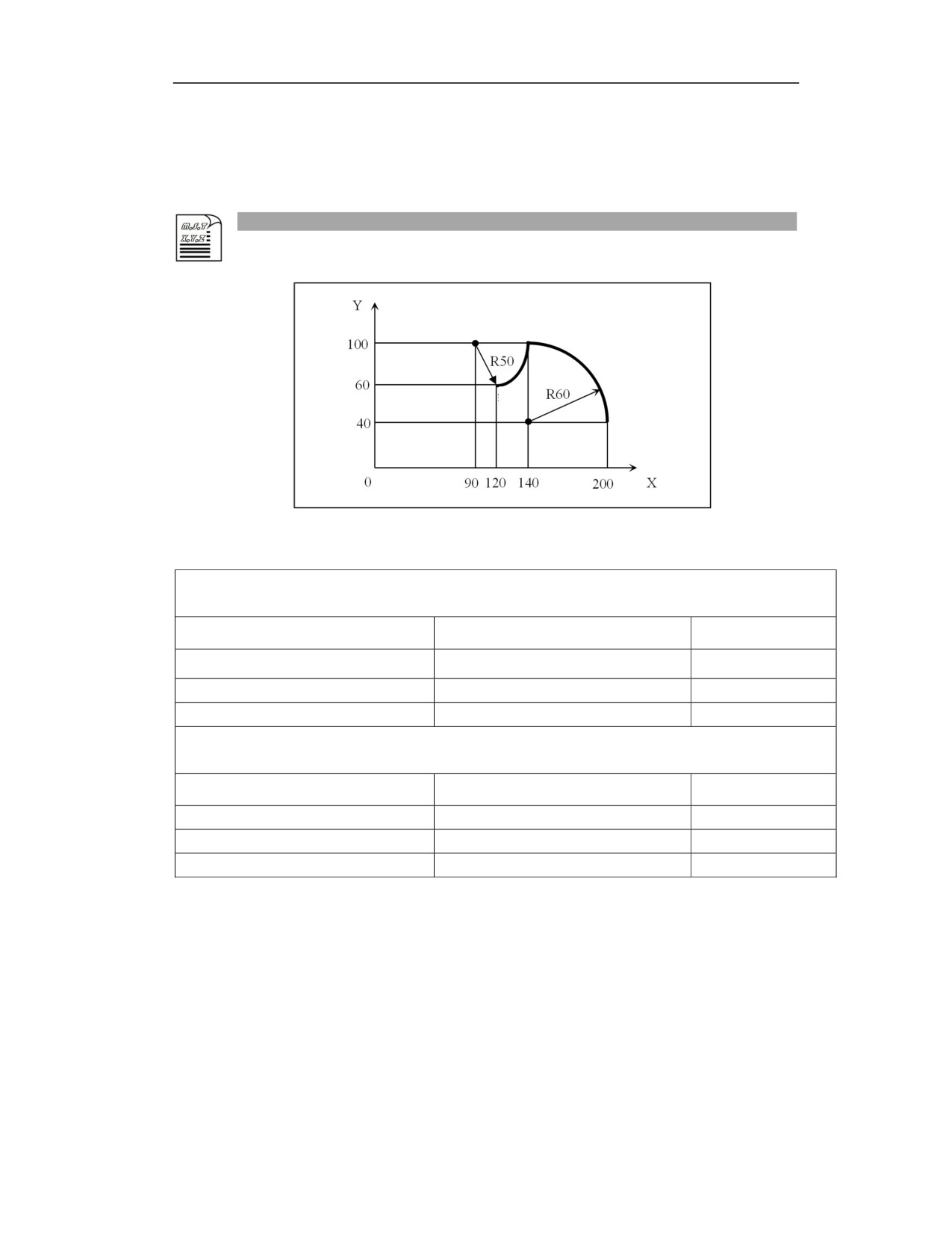
Example
End
Starting
point
The programming for the tool path shown in the figure above is as follows:
Programming with R
Absolute programming
Incremental programming
Commanded position
G54G0 X200.0 Y40.0 ;
G54G0 X200.0 Y40.0;
(X200、Y40)
G90 G03 X140.0 Y100.0 R60.0 F3000 ;
G91 G03 X-60.0 Y60.0 R60.0 F3000 ;
(X140、Y100)
G02 X120.0 Y60.0 R50.0;
G02 X-20.0 Y-40.0 R50.0;
(X120、Y60)
Programming with IJK
Absolute programming
Incremental programming
Commanded position
G54 G0 X200.0 Y40.0;
G54 G0 X200.0 Y40.0;
(X200、Y40)
G90 G03 X140.0 Y100.0 I-60.0 F3000;
G91 G03 X-60.0 Y60.0 I-60.0 F3000;
(X140、Y100)
G02 X120.0 Y60.0 I-50.0;
G02X-20Y-40I-50.0
(X120、Y60)
10
11.5
3D Circular Interpolation(G02.4/G03.4)
Function and Purpose
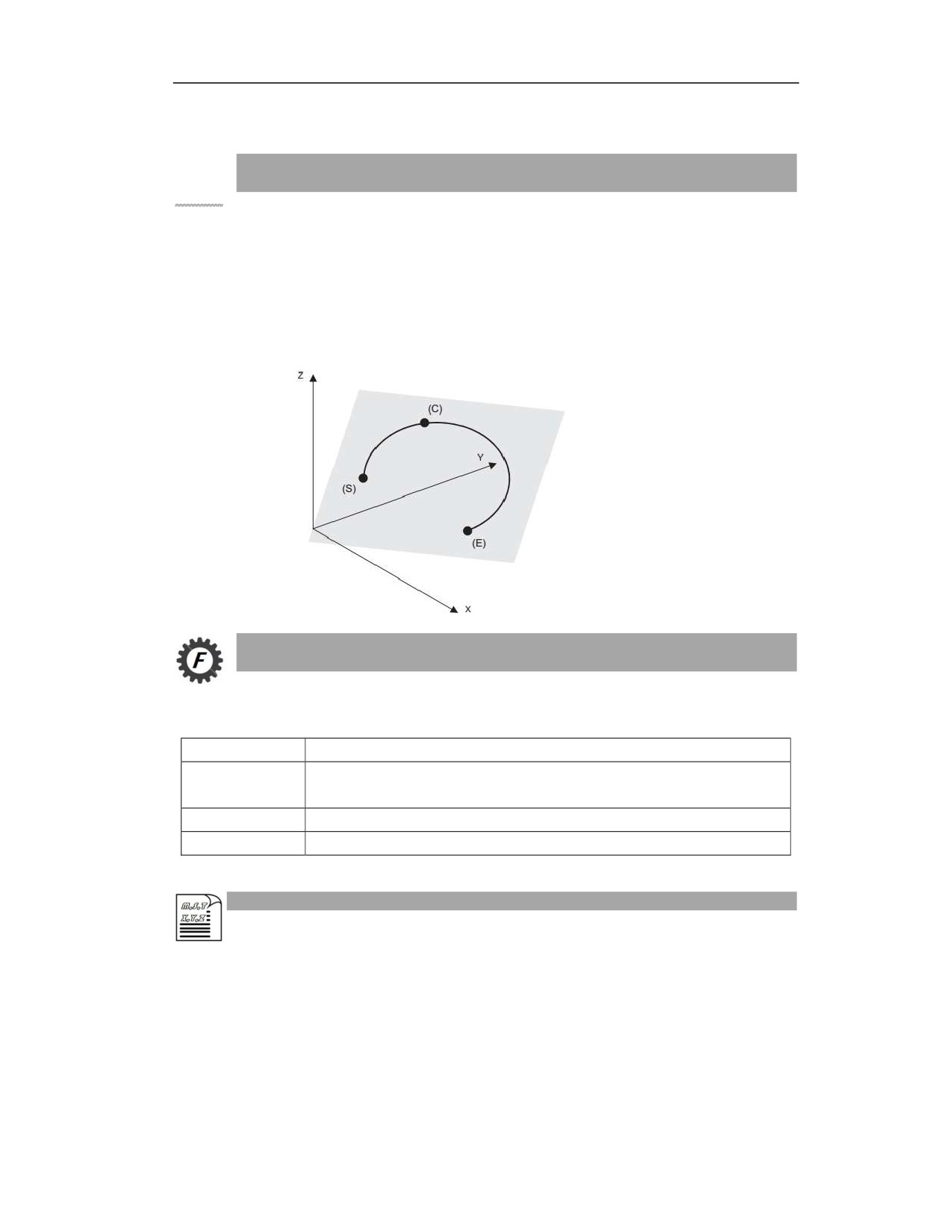
To execute the circular interpolation in three-dimensional space, in addition to the starting point
(current position) and end point, it is also necessary to specify any point on the arc (intermediate
point). Based on the 3 points (starting point, intermediate point, end point), the defined arc can be
processed.
Currently the system has not yet opened this command.
(S) Starting point (current position)
(E) End point
(C) Intermediate point
Command Format
G02.4/G03.4 X__Y__Z__I__J__K__ F__ ; (α is the auxiliary axis)
Parameter
Meaning
The coordinate value. With the mode of G90 or G91, it is expressed as an absolute
X, Y, Z, α
position or an incremental position
I, J, K
The coordinates of the intermediate point in the space
F
Feedrate(mm/min)
Example
Three arcs in space are machined as shown below
10
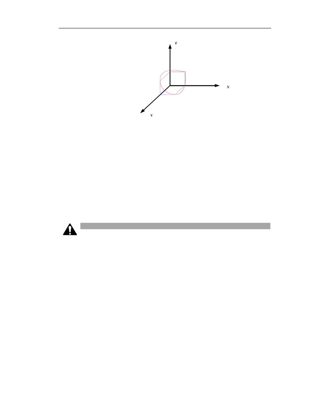
%877
G90 X80 Y0 Z80
F2000
G64
G03.4 X80 Y-80 Z0 I88 J0 K0
X0 Y-80 Z80 I32 J-74 K32
X80 Y0 Z80 I0 J0 K88
M30
Note
(1) The intermediate point is specified by IJK, whether in G90 or G91 mode, it is always the
directed distance from starting point to end point.
(2) G02.4 is same as G03.4, cannot specify the rotation direction.
(3) When any two of the circular starting point, intermediate point and end point coincide or the
three points are in the same straight line, the system will alarm.
(4) Please disable tool radius compensation function during 3D circular compensation.
(5) 3D circular interpolation cannot be used to specify the full circle (the starting point is
inconsistent with the end point); if need to specify the full circle, user could divide the full circle
into several segments.
10
11.6
Thread Cutting(G32)(T)
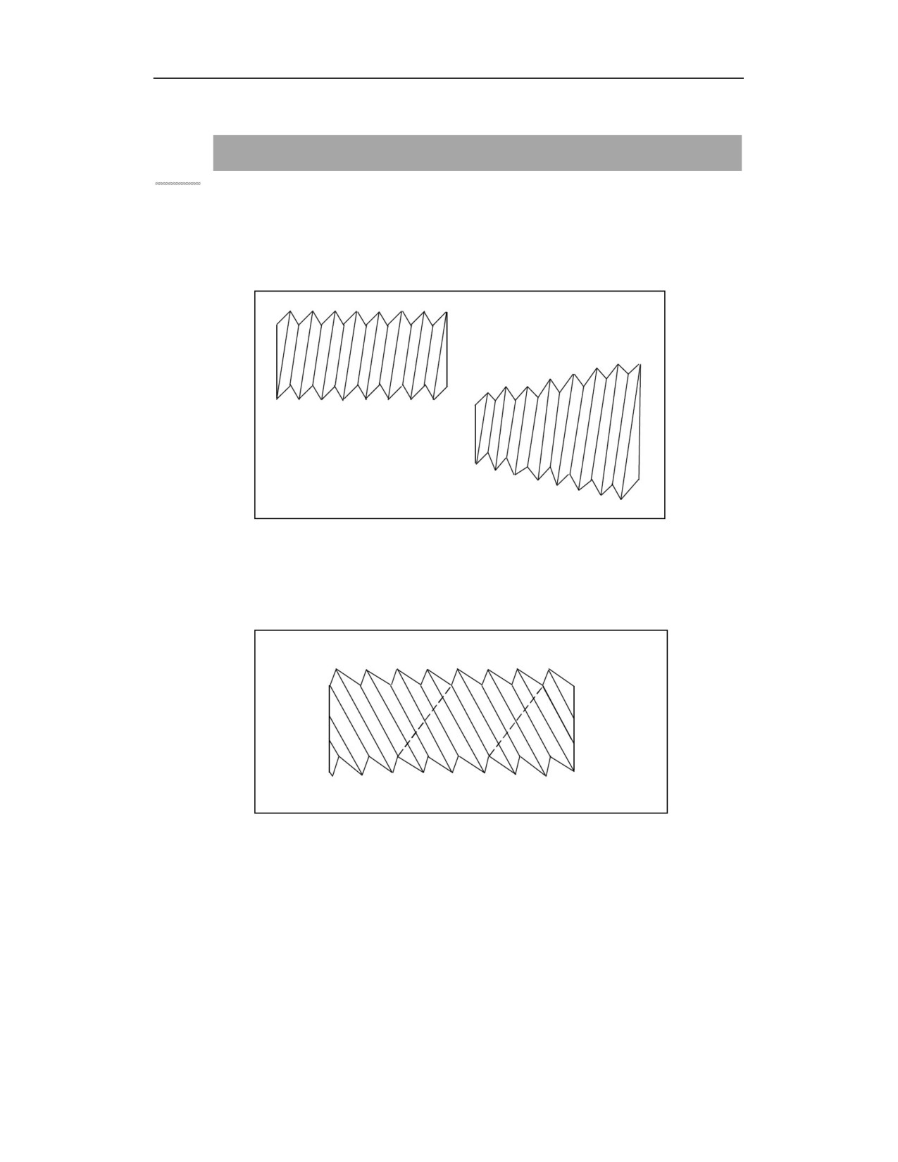
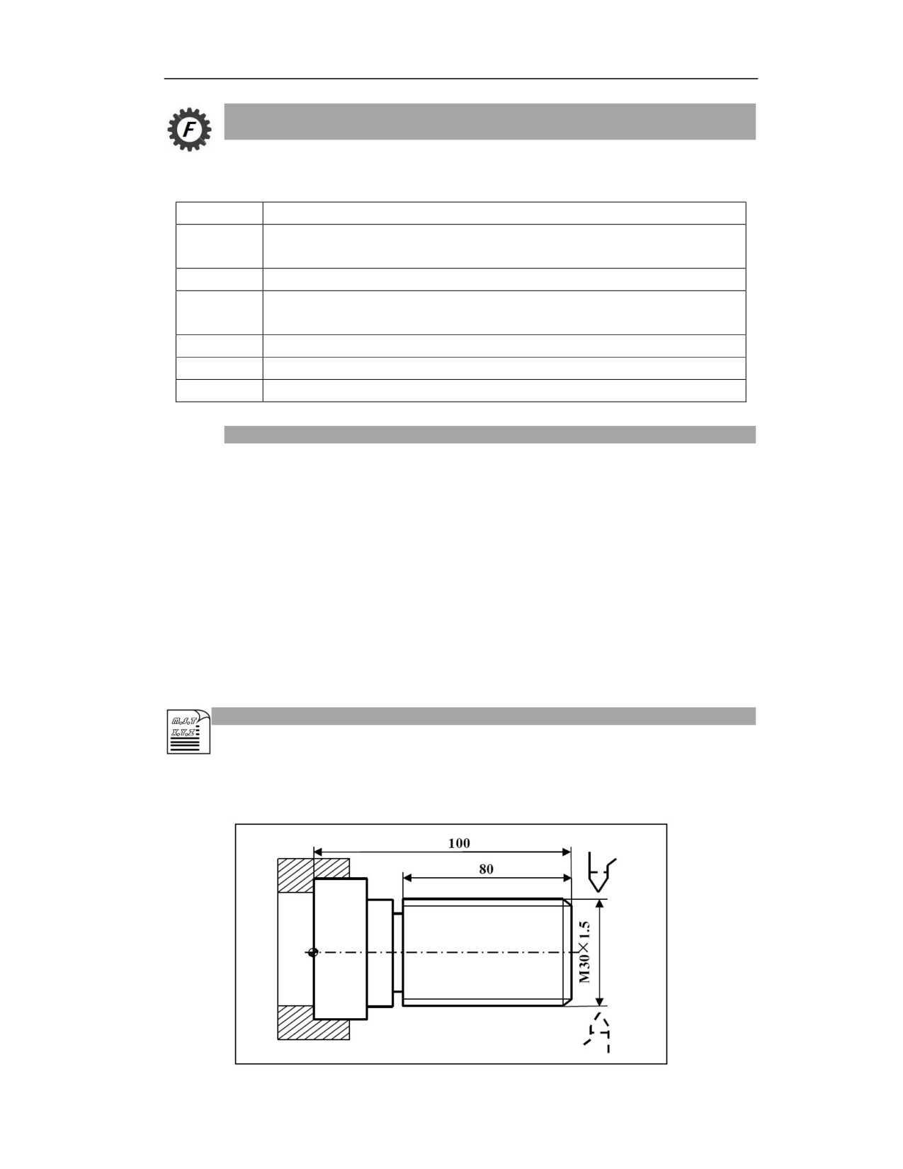
Function and Purpose
The tool feeds while the spindle rotates, so that different types of threads can be machined, such
as variable-pitch threads and multi-start threads. As shown below:
1. Equal-pitch single-start thread
2. Equal-pitch multi-start thread
Specify the thread starting angle P to process multi-start threads. If P=180 degrees, the double-
start thread can be processed.
10
Command Format
G32 X(U)_ Z(W)_ F_ P_ R_ E_
Parameter
Meaning
XZ
Coordinates of thread end point (G90)
Incremental value of thread end point relative to thread starting point (G91)
UW
Incremental value of thread end point relative to thread starting point
F
Thread lead; thread pitch for single-start thread (projection distance in the long axis
direction)
P
Angle of thread starting point
R
Undercut on Z axis, in incremental, can be omitted
E
Undercut on X axis, in incremental radius, can be omitted
Description
The undercut amount is the size of the incomplete thread profile. The undercut length (axial
dimension) of the ordinary thread is generally 1 to 2 times the pitch, and the radial length should
be the thread height.
For the undercut machining, R specifies the distance on Z axis, and E specifies the distance on X-
axis. The proportional relationship between the two determines the angle of undercut.
The signs of R and E values determines the undercut machining direction. The undercut
machining direction should be consistent with the thread machining direction; otherwise the
complete thread profile will be damaged.
Example
Programming for the thread shown as below. The thread lead is 1.5mm, and the feed amount
(diameter value) each time is 0.8mm, 0.6 mm, 0.4mm, 0.16mm.
11
%3316
N1 T0101
(Set the coordinate system, select the No.1 tool)
N2 G00 X50 Z120
(Move to the starting point)
N3 M03 S300
(Spindle rotates at 300r/min)
N4 G00 X29.2 Z101.5
(Move to the thread starting point, acceleration stage 1.5mm,
feed
depth 0.8mm)
N5 G32 Z19 F1.5
(Cutting to the thread end point, deceleration stage 1mm)
N6 G00 X40
(Rapid traverse retraction on X axis)
N7 Z101.5
(Rapid traverse retraction to thread starting point on Z axis)
N8 X28.6
(Rapid traverse to thread starting point on X axis with the feed depth 0.6mm)
N9 G32 Z19 F1.5
(Cutting to the thread end point)
N10 G00 X40
(Retraction on X axis)
N11 Z101.5
(Retraction to thread starting point on Z axis)
N12 X28.2
(Rapid traverse to thread starting point on X axis with feed depth 0.4mm)
N13 G32 Z19 F1.5
(Cutting to thread end point)
N14 G00 X40
(Retraction on X axis)
N15 Z101.5
(Retraction to thread starting point on Z axis)
N16 U-11.96
(Retraction to thread starting point on X axis with feed depth 0.16mm)
N17 G32 W-82.5 F1.5
(Cutting to thread end point)
N18 G00 X40
(Retraction on X axis)
N19 X50 Z120
(Return to tool setting point)
N20 M05
(Spindle stops)
N21 M30
(Main program ends and resets)
Note
(1) Do not modify the feedrate override and spindle override during thread cutting;
(2) It is very dangerous to stop the tool feed of thread cutting without stopping the spindle, it will
suddenly increase the cutting depth. Therefore, the dwell function is invalid during thread cutting.
If the feed hold button is pressed during thread cutting, the feed hold is invalid. Feed hold is only
valid during non-thread processing;
(3) When thread cutting is executed in the single block state, the tool stops after the first non-
thread cutting is executed.
11
(4) During thread cutting, the working mode is not allowed to change from auto mode to JOG
mode, incremental mode or reference point return mode.
11.7
Helical Interpolation(G02/G03)
Function and Purpose
In addition to specifying circular interpolation, G02 and G03 can be used to perform helical
interpolation by specifying the movement distance of the third axis, and perform thread milling
and cavity-type parts hole processing.
Command Format
G02
I_J_
G1
X_Y_Z_
L_F_ Circular interpolation in XY plane
7
}
{
}
G03
R_
G02
I_K_
G1
X_Z_Y_
L_F_
Circular interpolation in ZX plane
8
G03
}
{
R_
}
G02
J_K_
G1
Y_Z_X_
L_F_
Circular interpolation in YZ plane
9
}
{
}
G03
R_
Parameter
Meaning
G02
Circular interpolation CW
G03
Circular interpolation CCW
G17
Circular interpolation in XY plane
G18
Circular interpolation in ZX plane
G19
Circular interpolation in YZ plane
X
Movement amount on X axis of circular interpolation or X coordinate of circular end
Y
Movement amount on Y axis of circular interpolation or Y coordinate of circular end
Z
Z axis coordinate of end point in absolute programming; incremental amount of end
point on Z axis relative to starting point (even with L)
R
Radius (with sign, "+" minor arc, "-" major arc)
I
The distance from the circular starting point to the circular center on X (with sign);
for the conical interpolation in XZ plane, it is the height increase or decrease of one
spiral rotation.
J
The distance from the circular starting point to the circular center on Y (with sign)
11
K
The distance from the circular starting point to the circular center on Z (with sign)
F
Feedrate, modal
L
Number of helical rotations (positive number without decimal point)
Description
(1) The rotation direction of helical interpolation refers to the direction of the arc projected to the
two-dimensional plane
(2) For full circle programming, if all the position commands (X, Y, Z) are omitted during
programming, it means that the start point and end point coincide. At this time, a full circle is
specified with (I, J, K). If R is used for specifying, it becomes a 0 degree arc, and the system
alarms.
Example
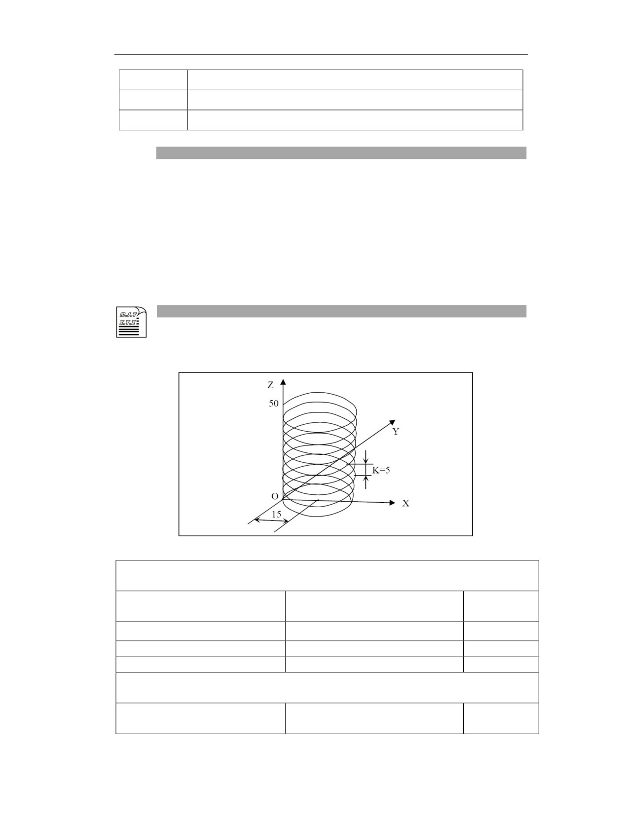
Process the helix as shown below,
Programming with R
Commanded
Absolute programming
Incremental programming
position
G54 G0 X30 Y0 Z0;
G54 G0 X30 Y0 Z0;
(X30、Y0、Z0)
G90 G03 X0 Y0 Z50 R15 L10 F3500
G91 G03 X-30 Y0 Z50 R15 L10 F3500
(X0、Y0、Z50)
M30
M30
Programming with IJK
Commanded
Absolute programming
Incremental programming
position
11
G54 G0 X30 Y0 Z0;
G54 G0 X30 Y0 Z0;
(X30、Y0、Z0)
G90 G03 X0 Y0 Z50 I-15 J0 K0 L10
G91 G03 X-30 Y0 Z50 I-15 J0 K0 L10
(X0、Y0、Z50)
F3500
F3500
M30
M30
11.8
Imaginary Axis Specifying and Sine Interpolation (G07)
Function Purpose
If an axis is designated as an imaginary axis, the axis only participates in the interpolation
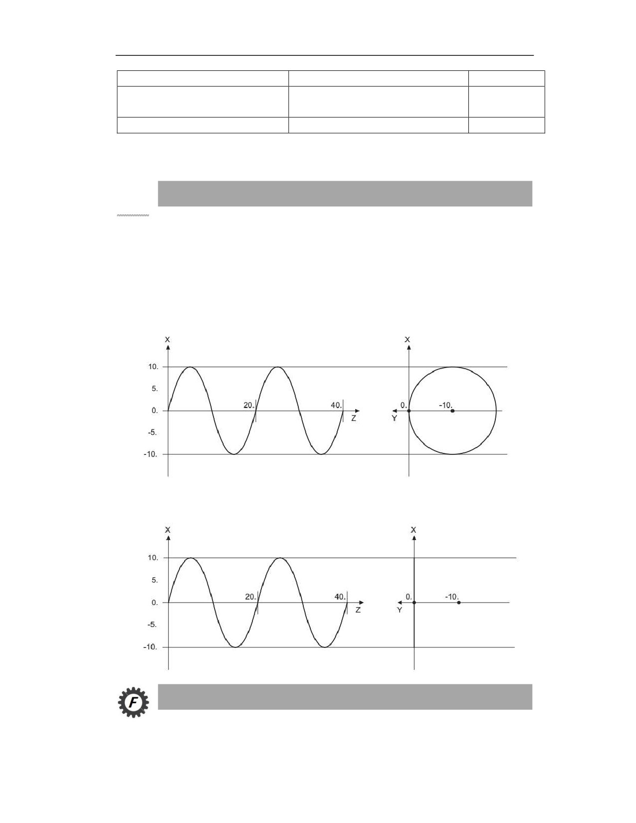
computing, but does not move. If a certain axis is designated as the imaginary axis (axis without
actual movement) in the helical interpolation, its running path is: the projected path of the helical
interpolation on the plane perpendicular to the imaginary axis. This running path corresponds to
sine line and cosine line (SIN interpolation or COS interpolation).
Normal helical interpolation
Helical interpolation in imaginary axis (Y-axis is the imaginary axis)
Command Format
G07 α0(α1);
11
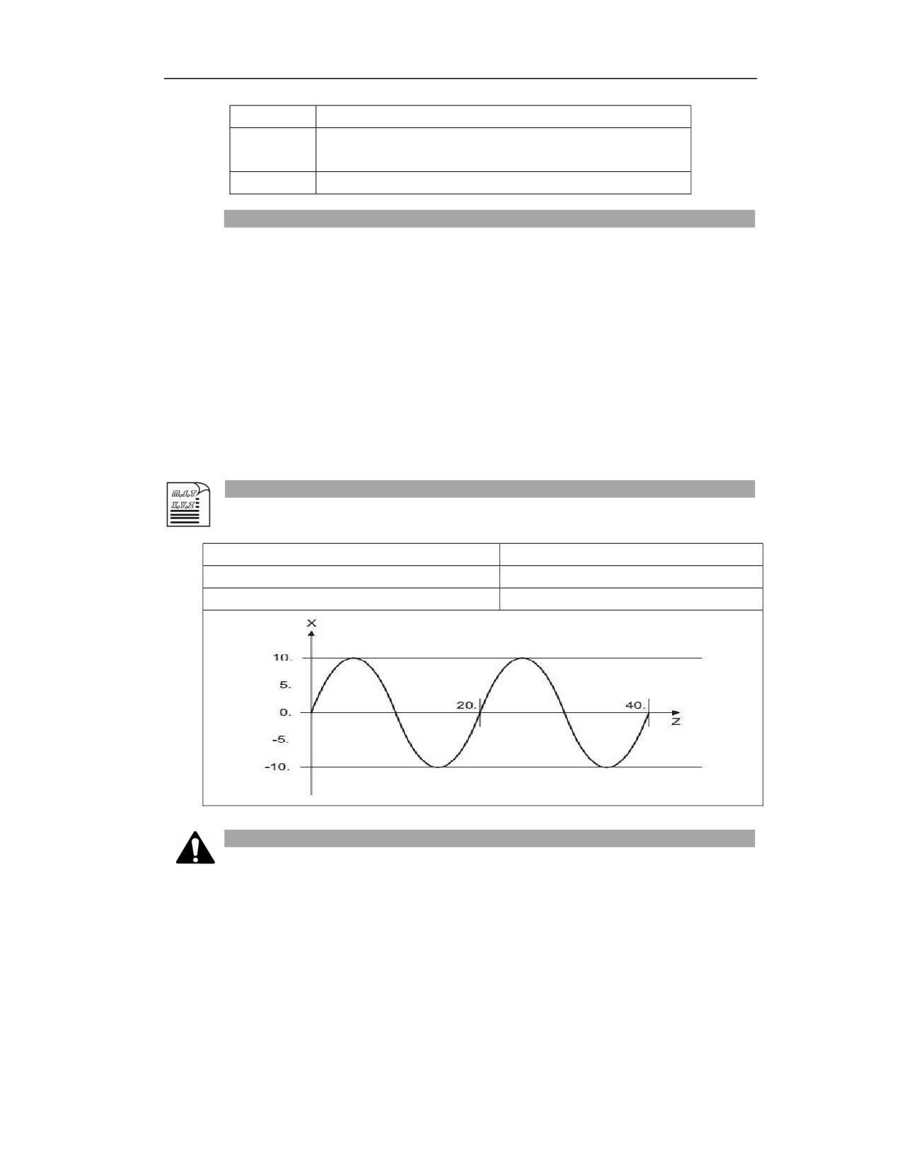
Parameter
Meaning
α0
Imaginary axis interpolation mode is enabled
α1
Imaginary interpolation mode is disabled
α
Axis name of imaginary axis
Description
(1) Between "G07 α0;" and "G07 α1;", the α axis is an imaginary axis.
(2) The axis designation for imaginary axis setting can be applied to all axes of the NC axis.
(3) Multiple imaginary axes can be set.
(4) If a command other than the imaginary axis interpolation mode Enable (0)/Disable (1) is
enabled, it will be regarded as imaginary axis interpolation Disable (1). However, when an
imaginary axis is specified without the value, it is regarded as imaginary axis interpolation Enable
(1).
Example
N01 G07 Y0 ;
Y axis is used as an imaginary axis.
N02 G17 G02 X0 Y0 Z40 I0 J-10 L2 F50
SIN interpolation is performed in XZ plane
N03 G07 Y1 ;
Y axis is restored to the actual axis.
Note
(1) The interpolation functions that can be used in the imaginary axis interpolation are helical
interpolation and spiral interpolation.
(2) The imaginary axis interpolation needs to be canceled at the time of high-speed high-precision
(G05.1Q1/G05.1Q2/G05.1Q3)
(3) The imaginary axis interpolation is valid during auto operation, and invalid during JOG
operation. The imaginary axis interpolation is also valid during handwheel interpolation.
(4) Although the traverse command of the imaginary axis is ignored, when the feedrate is allocated,
11
the allocation of the imaginary axis is the same as the actual axis.
(5) If the imaginary axis is set again during the imaginary axis interpolation, no error will occur,
and the effect of the imaginary axis will continue to be maintained.
(6) When the imaginary axis is canceled, the usage of the non-imaginary axes is not affected.
(7) If reset, the imaginary axis is canceled.
11.9
Polar Coordinate Interpolation(G12/G13)
Function and Purpose
Polar coordinate interpolation is a contour control function, which converts the programmed
position in the Cartesian coordinate system into linear axis movement (tool movement) and rotary
axis movement (workpiece rotation). It can be programmed on the selected plane (polar
coordinate interpolation plane) to complete the milling or grinding of the face contour of the rotary
workpiece.
In the polar coordinate interpolation mode, linear interpolation and circular interpolation can be
commanded, and absolute programming, incremental programming, diameter programming,
radius programming, tool radius and length compensation can be used (polar coordinate
interpolation is performed based on the compensated path).
This function is often used in turning centers with power head tools.
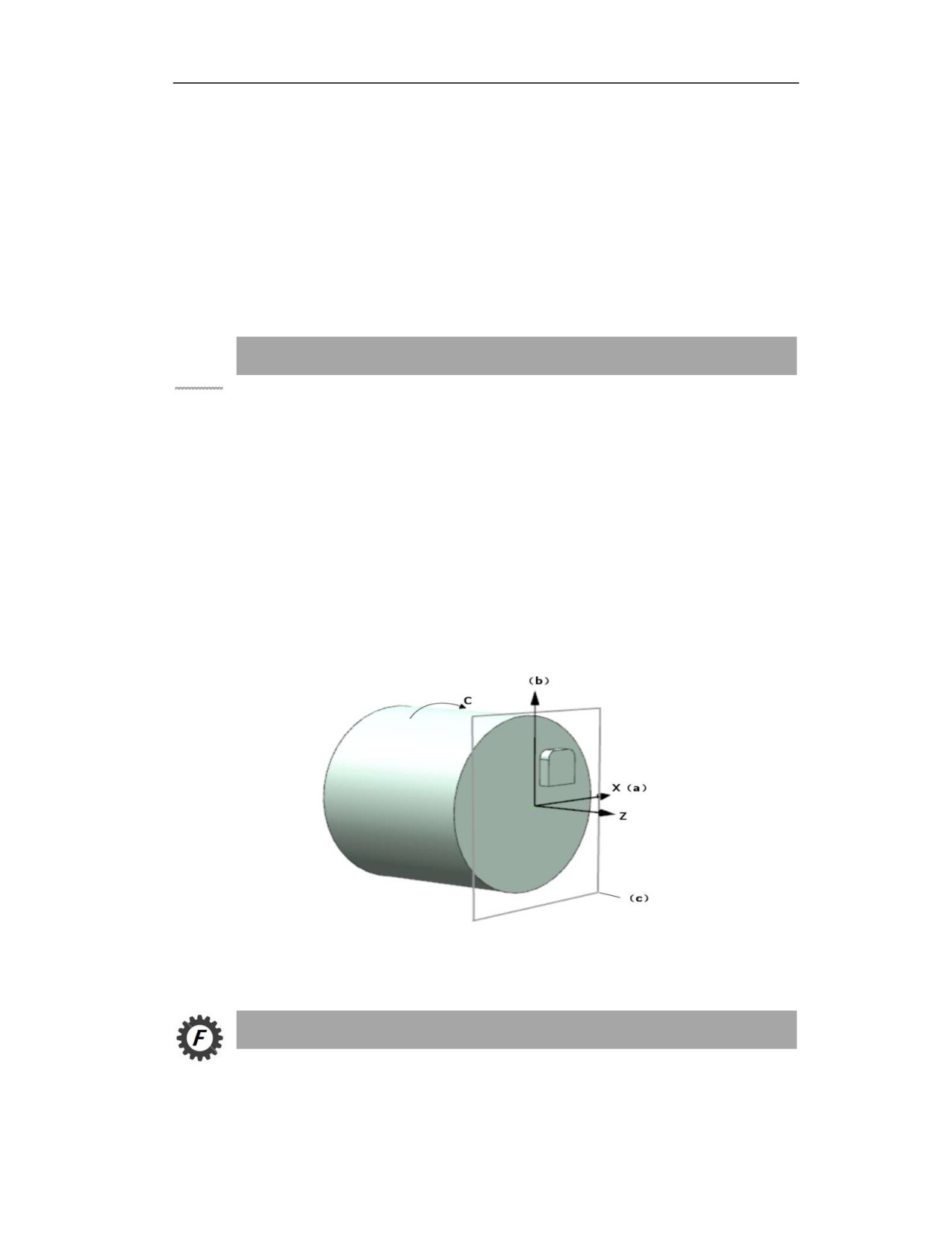
(a) Linear axis
(b) Rotary axis (imaginary axis)
(c) Polar coordinate
interpolation plane (G17 plane)
Command Format
G12 ;
11
G13 ;
Parameter
Meaning
G12
Polar coordinate interpolation is enabled.
G13
Polar coordinate interpolation is disabled.
Description
1)Polar coordinate interpolation plane
The polar coordinate interpolation plane uses the linear axis as the first right-angled axis of the
plane, and the imaginary axis orthogonal to the linear axis as the second axis of the plane. The
plane composed of 2 orthogonal axes is the polar coordinate interpolation plane, and the polar
coordinate interpolation is executed on this plane. In the polar coordinate interpolation, the origin
of the workpiece coordinate system is regarded as the origin of the coordinate system.
2)Polar coordinate interpolation parameter setting
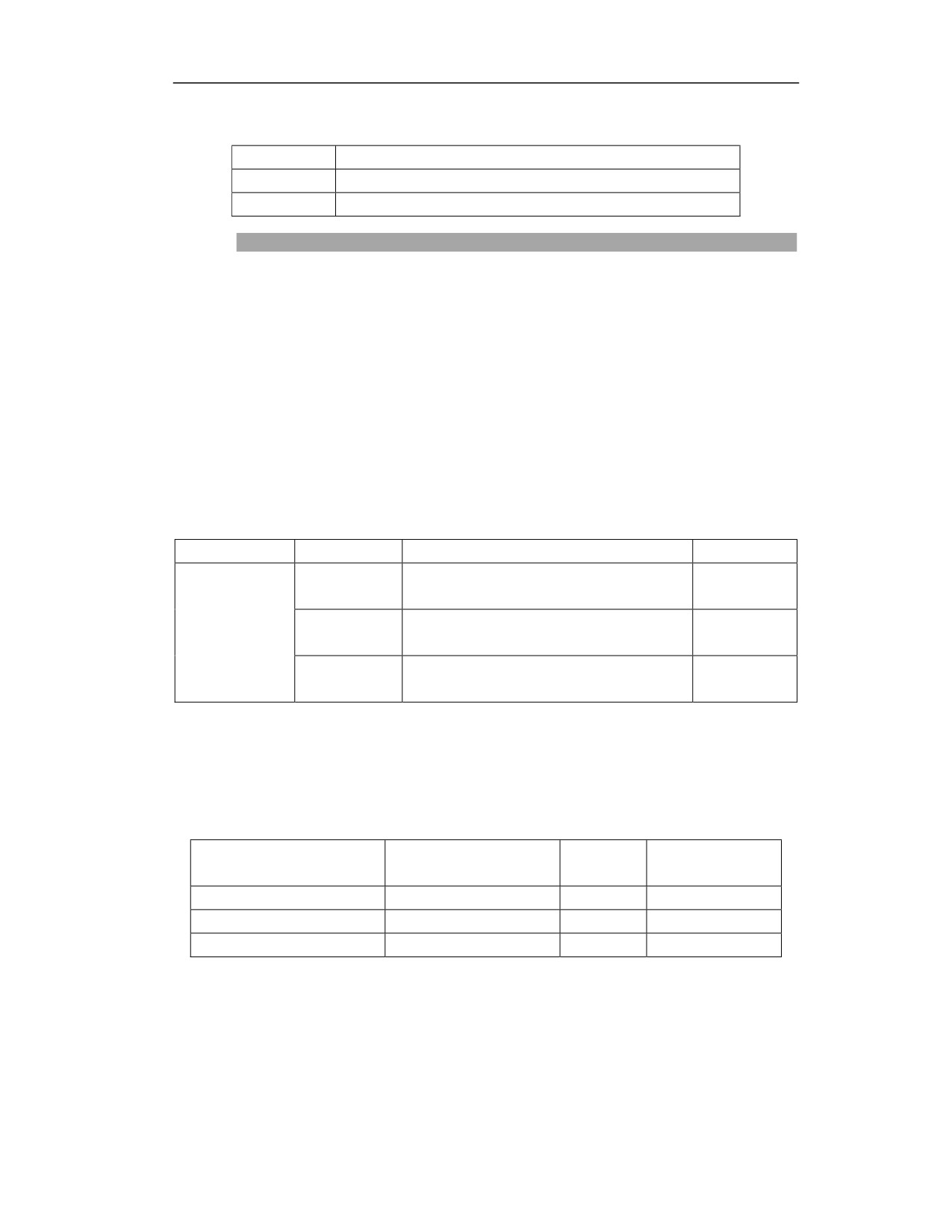
The linear axis, rotary axis and imaginary axis in polar coordinate interpolation need to be set in
the parameters in advance. The relevant parameters are as follows:
Parameter name
Parameter
Description
Default
Parm040095
Linear axis No. in polar coordinate
0 (X axis)
interpolation
Channel
Parm040096
Rotary axis No. in polar coordinate
5 (C axis)
parameter CH0
interpolation
Parm040097
Imaginary axis No. in polar coordinate
1 (Y axis)
interpolation
The linear axis and the imaginary axis of the polar coordinate interpolation coordinate system are
determined by the above parameters. The linear axis is used as the horizontal axis of coordinate
system in the polar coordinate interpolation and the imaginary axis is used as the vertical axis. In
the execution plane formed by the linear axis and the imaginary axis, the corresponding circular
interpolation address words are shown in the following table:
Parm040095 parameter
Linear axis name in polar
Plane
Circular definition
setting
coordinate interpolation
address words
0
X
G17
I, J, R
1
Y
G18
J, K, R
2
Z
G19
I, K, R
3)Imaginary axis eccentricity compensation
When there is an error in the imaginary axis direction from the rotation axis center of the first axis
in the plane, that is, the rotation axis center is not on the X axis, this function can be used for the
compensation, and the system will perform polar coordinate interpolation after calculating the
error. Enable this function and set the Parm040099 parameter in the channel parameters as the
measurement error value.
11
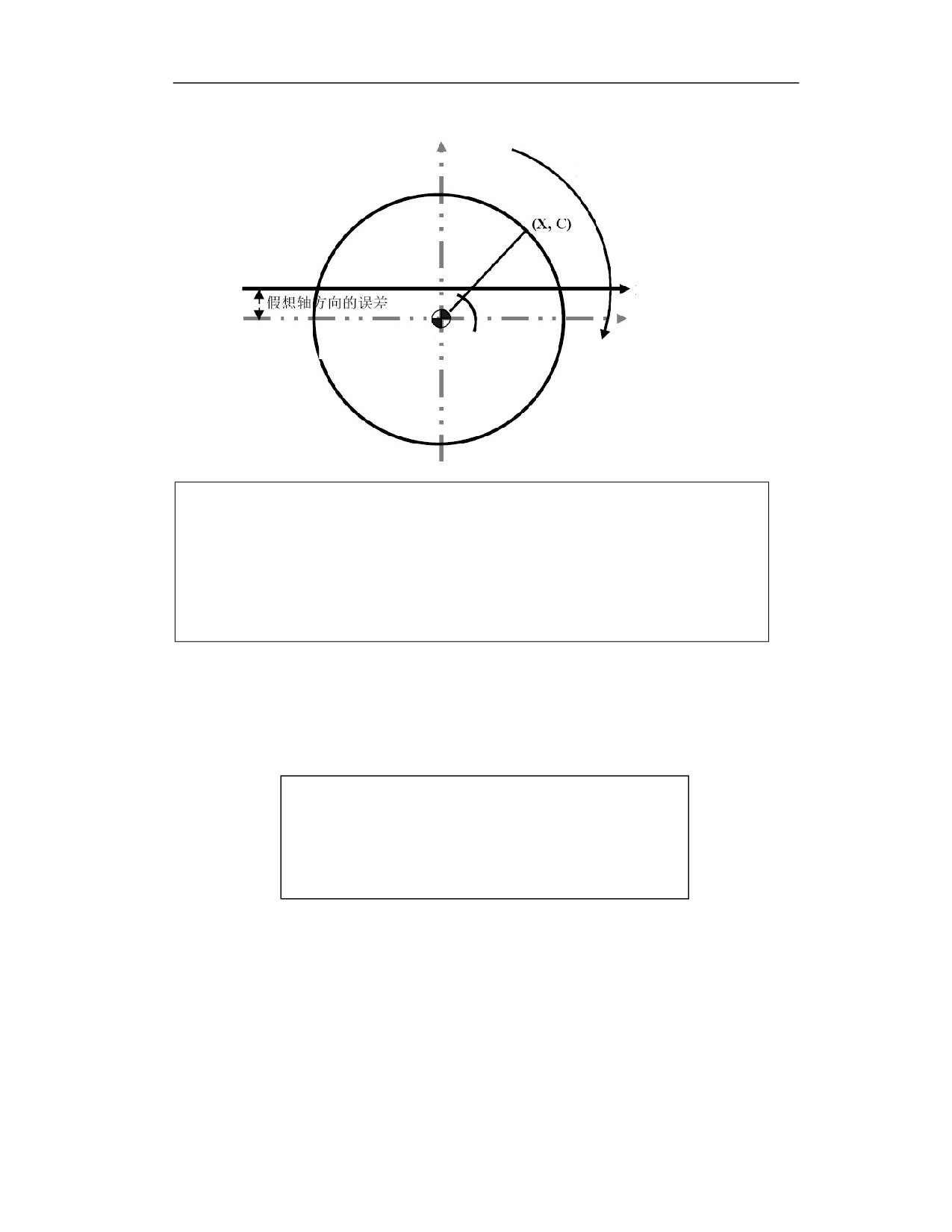
Imaginary axis (C axis)
Rotary axis
Error in the imaginary
axis direction
X axis
Rotary axis center
(X,C) The point in the X-C plane (the rotary axis center is used as zero of X-C plane)
X X axis coordinate in the X-C plane
C Coordinate of imaginary axis in the X-C plane
P Error in the imaginary axis direction
4)Coordinate system offset in polar coordinate interpolation
In polar coordinate interpolation, the following format can be used to translate the workpiece
coordinate system.
G12 X_C_; (Polar coordinate interpolation used for X axis and C axis)
G12 Y_A; ( Polar coordinate interpolation used for Y axis and A axis)
G12 Z_B; (Polar coordinate interpolation used for Z axis and B axis)
X-C (Y-A, Z-B) is used to specify the coordinate value of the center position of the rotary axis C
(A, B) in the interpolation plane relative to the origin of the workpiece coordinate system (see the
figure below)
11
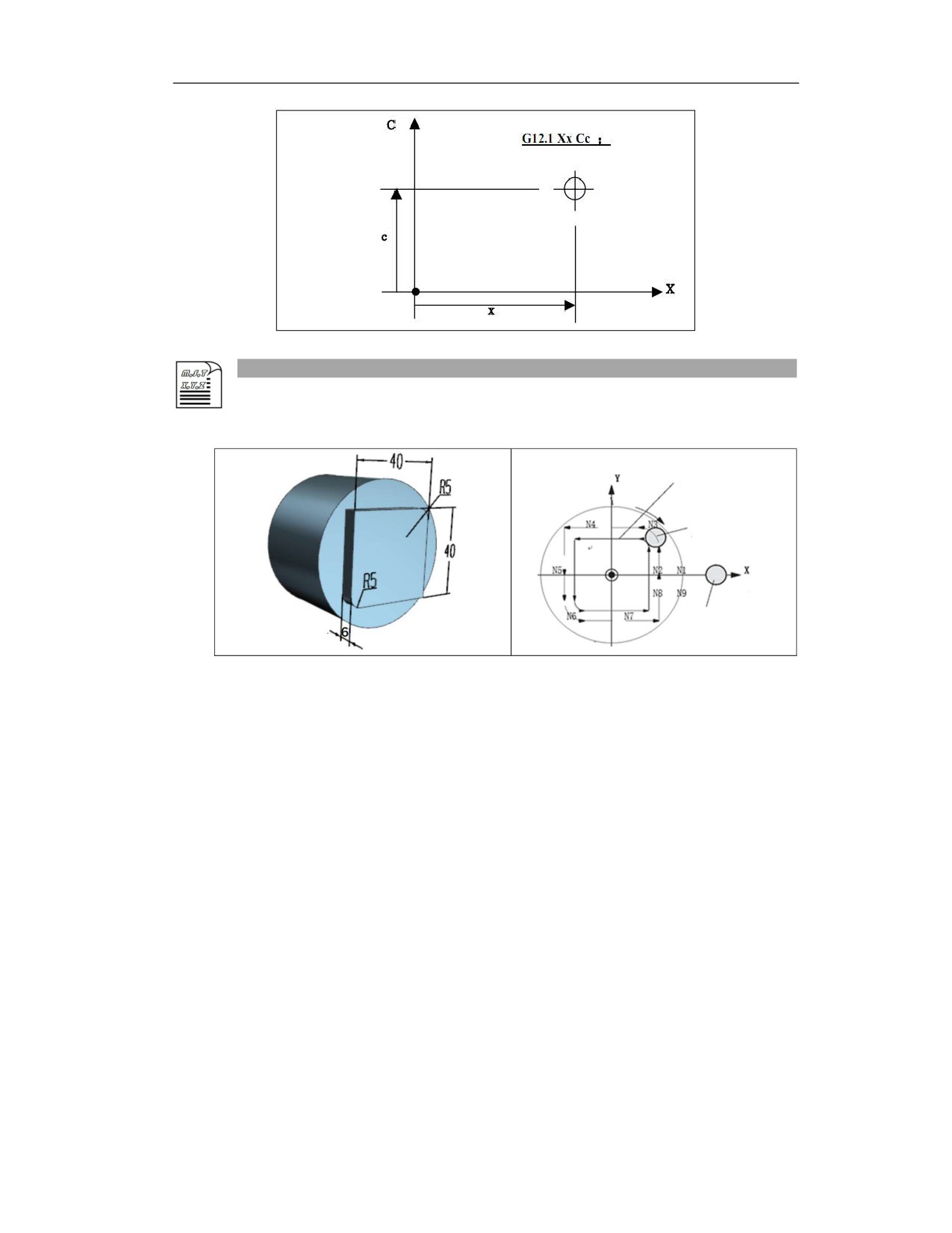
C axis center
Workpiece coordinate
system origin
Example
Example 1: Face contour milling
Contour path
Tool path
Tool
%1234
G54
T0101;The workpiece coordinate system is built at the center of rotation on the right end
of the blank, with end milling cutter φ10
G108;Spindle is switched from speed mode to position mode
M103 S1=2000;Tool rotation CW
G37;Radius programming
G0X45Z50C0
G0Z-5
G12X0CO
G42D1G01X40F500(D1=5)
N1 G1X20
N2 C10
N3 G3X10 C20 R10
N4 G1X-20
N5 C-10
N6 G3X-10 C-20 I10 J0
N7 G1X20
N8 C0
N9 G40X40
11