HNC8 Series CNC Controller. Programming Manual (V2.4) - page 8
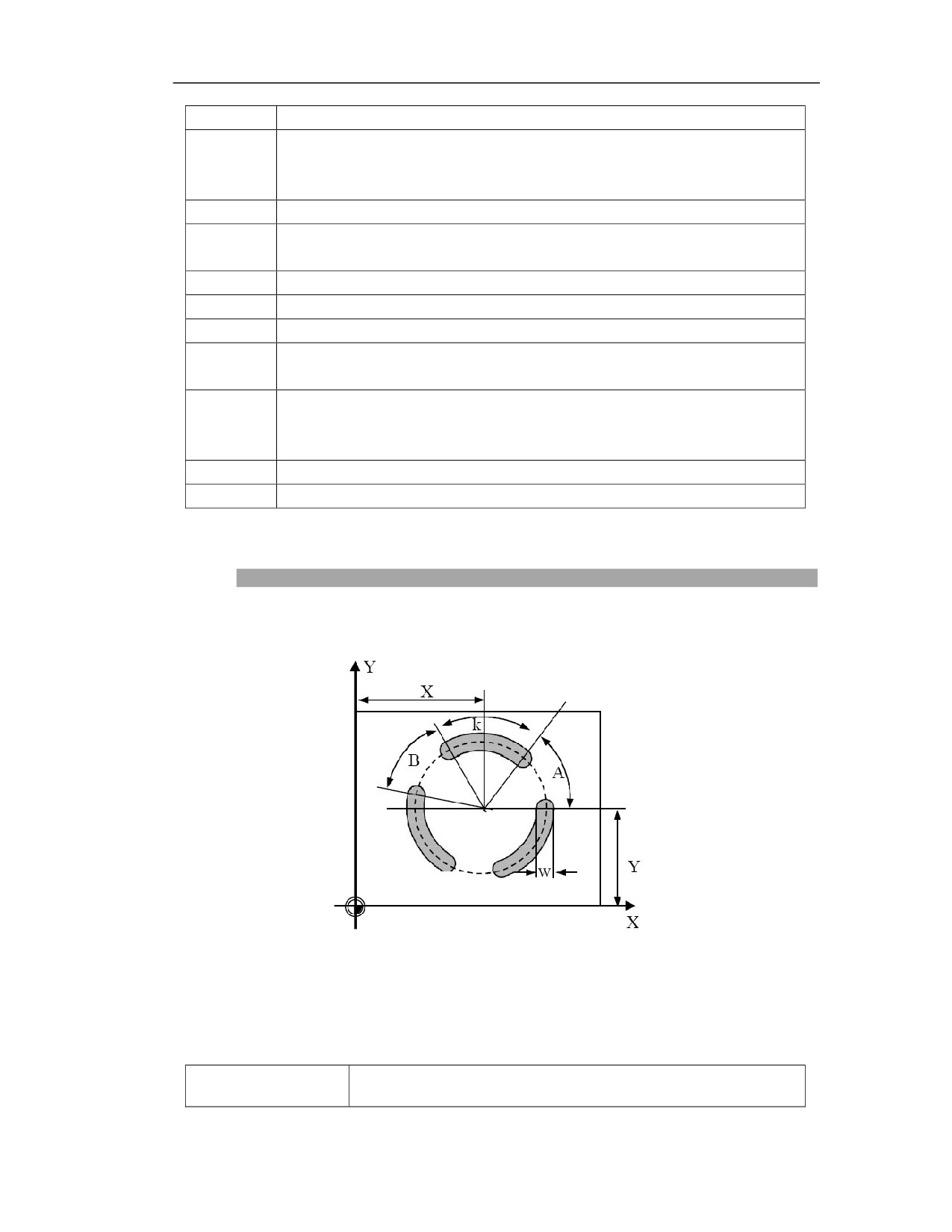
can be omitted when A=0)
Incremental angle (can be omitted when B=360/N; The negative value indicates the milling of
B
grooves in counterclockwise direction, and the positive value indicates the milling of grooves in
clockwise direction)
F
Milling speed in roughing
Max. feed depth in roughing (can be omitted when Q=groove depth-finishing allowance of
Q
groove bottom)
E
Finishing allowance of groove edge (can be omitted when E=0)
O
Finishing allowance of groove bottom (can be omitted when O=0)
U
Feedrate in finishing (can be omitted when U=F)
Spindle speed in finishing (can be omitted when P=spindle speed or default speed before
P
entering cycle)
Milling direction for grooving (can be omitted when C=3)
C
0:milling in the same direction; 1: milling in the reverse direction; 2: milling in G02 direction;
3: milling in G03 direction
D
Machining type (can be omitted when D=1) 1: roughing; 2: finishing
V
Tool radius
Description
Graphical representation
Milling direction
The spindle must be specified to rotate before entering the cycle. A reasonable milling direction
is calculated based on the spindle rotation direction M3/4 and the milling direction set by the user
before entering the cycle. The selection of the milling direction is shown in the following table:
Milling direction (cycle
Specify M03/M04 before entering cycle
280
parameter C)
M03 spindle rotation CW
M04 spindle rotation CCW
milling in the same
G03
G02
direction
milling in the reverse
G02
G03
direction
2:G02 direction
G02
G02
3:G03 direction
G03(1)
G03
省略 Omitted
G03
G03
Steps
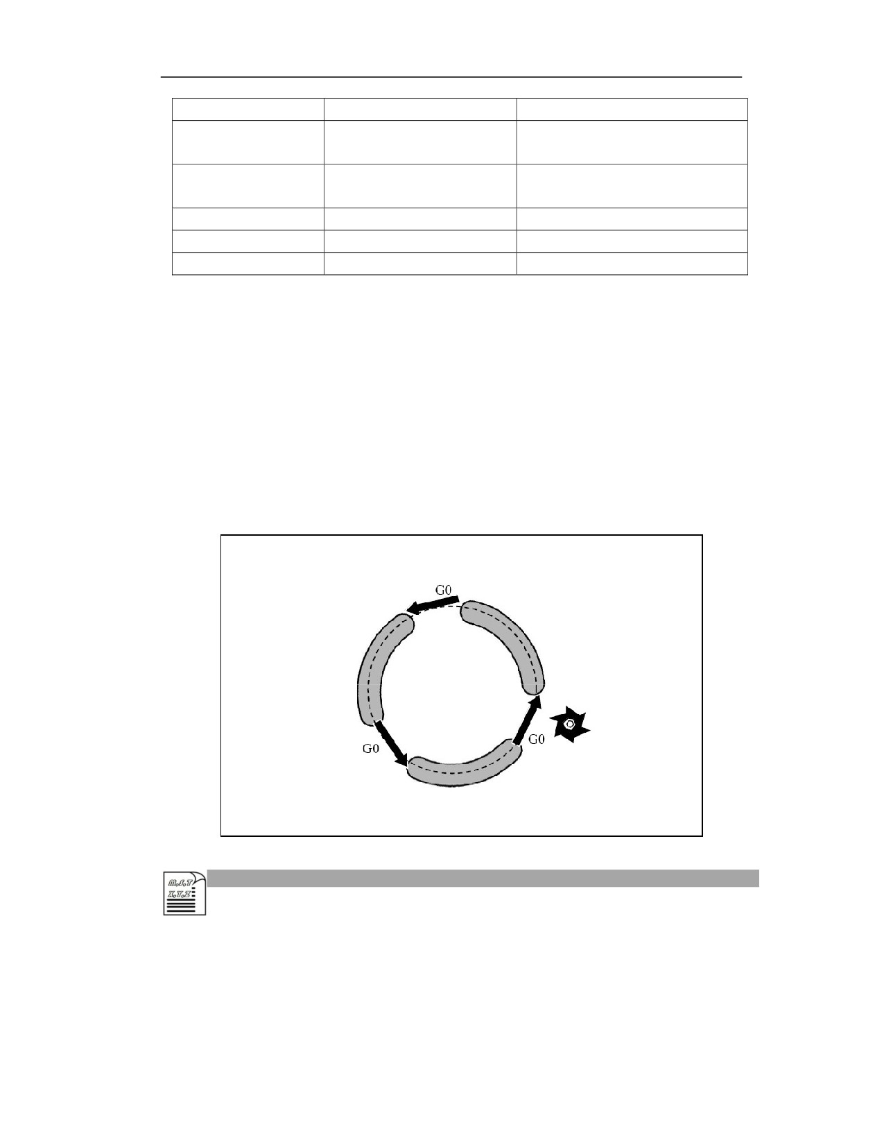
(1) When cycle runs, use G00 to reach the reference level R;
(2) Milling the current groove back and forth from inside to outside, the milling steps are similar to
G182;
(3) After finishing machining a groove, the tool retracts to the reference level and moves to the next
groove;
(4) After processing all grooves, retract the tool with G98/G99 to complete the cycle.
Example
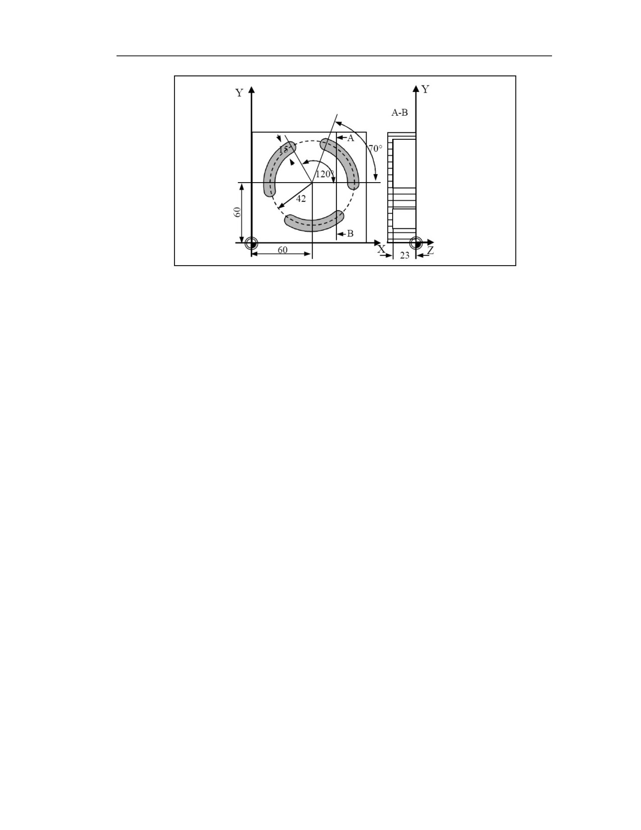
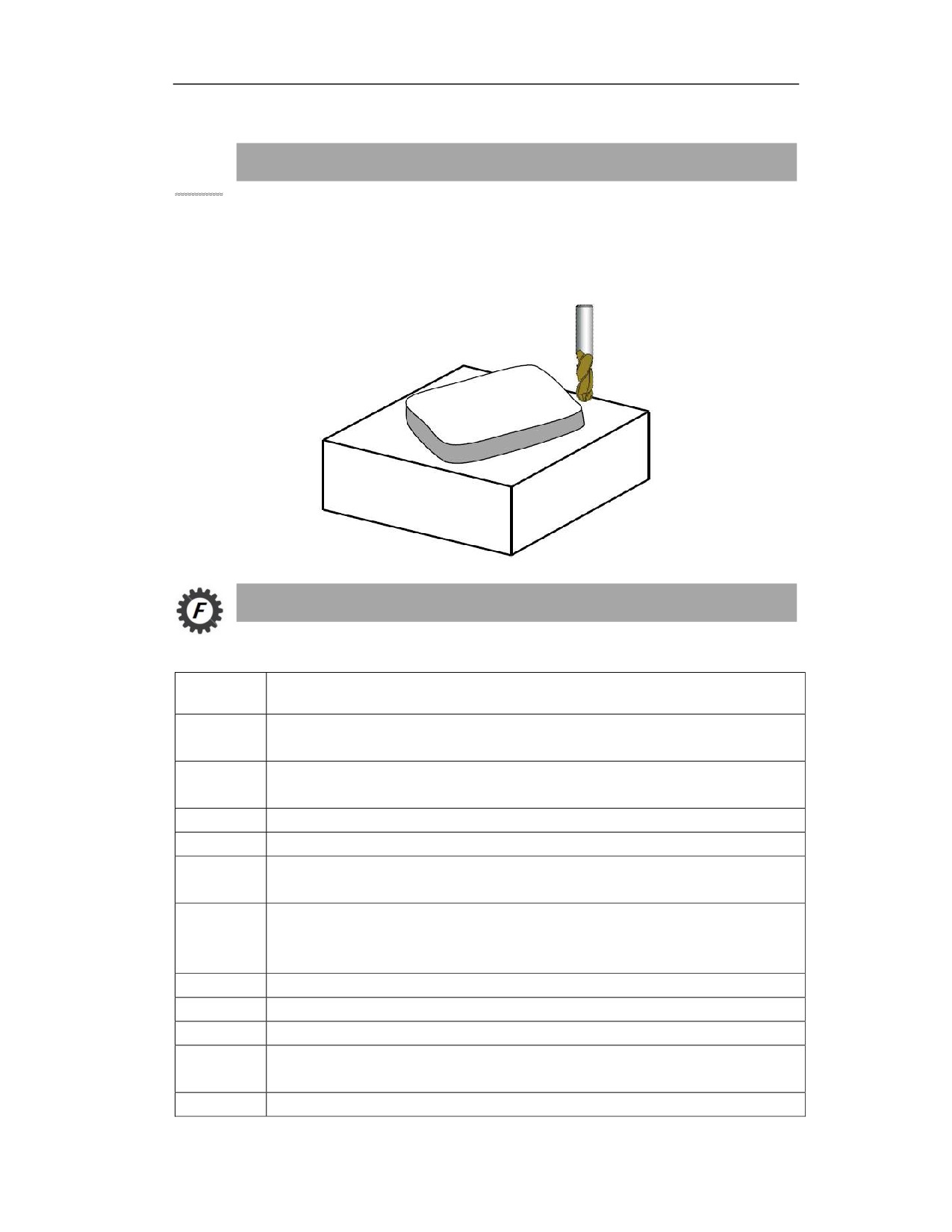
Machining three grooves on a circle with a center of (X60, Y60) and a radius of 42mm in the XY
plane. The groove size: width is 15mm, groove length angle is 70 degrees, groove depth is 23mm,
starting angle is 0 degrees, incremental angle is 120 degrees, the finishing allowance on the groove
contour is 0.5mm, and the depth of each feed is 6mm. The same speed and feed rate are used for
finishing and roughing. The finishing is completed in one cut, and the tool radius is 5mm.
281
%0528
N10 G54 G17 G90
N20 T10
N30 M06
N40 M03 S600
N50 G00 X60 Y60 Z5
N60G183R2Z-23N3K70W15X60Y60I42A70B120F100Q6E0.5O0.5V5
N70 M30
282
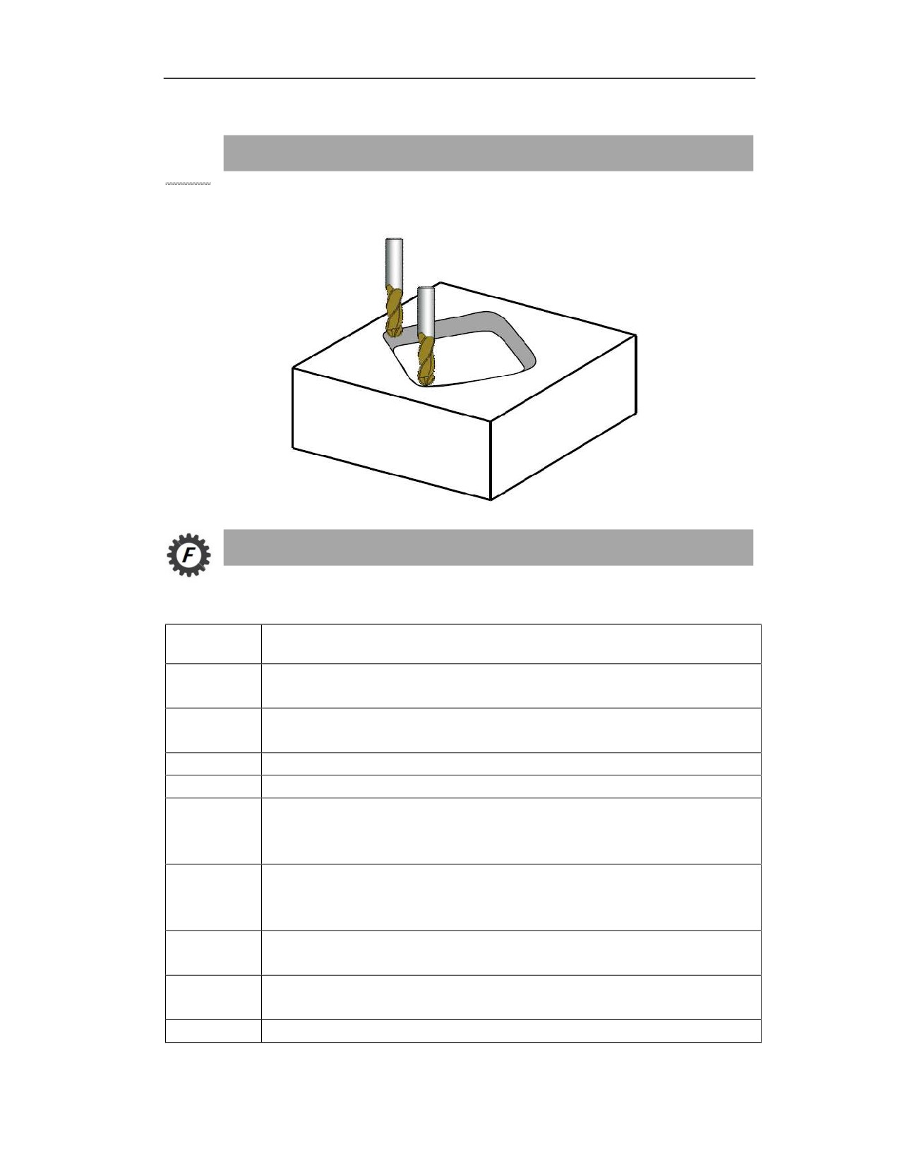
16.4.4 Rectangular Pocket Milling Cycle (G184)
Function and Purpose
This cycle is used for rough machining and finishing of rectangular pockets with circular corners.
Command Format
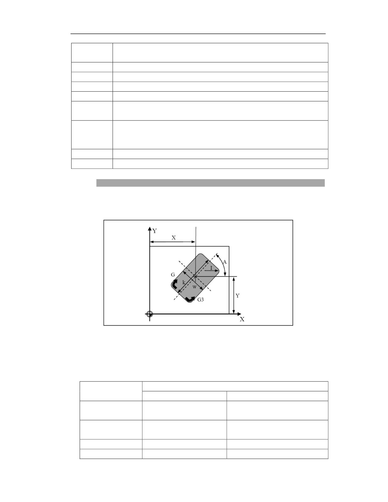
(G98/G99)G184R_Z_K_W_X_Y_I_A_F_ Q_E_O_H_U_P_C_D_V_;
Parameter
Meaning
Coordinates of R point in absolute programming; distance from initial level to R point
R
in incremental programming
Coordinate of pocket bottom in absolute programming; incremental value of pocket
Z
bottom relative to reference point R in incremental programming.
K
Pocket length
W
Pocket width
Center of pocket. Coordinate of the first axis in the current plane in absolute
X
programming; incremental value relative to the starting point in incremental
programming.
Center of pocket. Coordinate of the second axis in the current plane in absolute
Y
programming; incremental value relative to the starting point in incremental
programming.
Radius of circular corners of rectangular pocket (can be omitted or specified as 0 when
I
I=W/2)
The angle between the long side of the rectangular groove and the positive direction of
A
the first axis in the plane (can be omitted when A=0)
F
Milling speed in roughing
283
Max. feed depth in roughing (can be omitted when Q=groove depth-finishing allowance
Q
of groove bottom)
E
Finishing allowance of groove edge (can be omitted when E=0)
O
Finishing allowance of groove bottom (can be omitted when O=0)
H
Max. feed depth in finishing (can be omitted when H=Q)
U
Feedrate in finishing (can be omitted when U=F)
Spindle speed in finishing (can be omitted when P=spindle speed or default speed before
P
entering cycle)
Milling direction (can be omitted when C=3)
C
0:milling in the same direction; 1: milling in the reverse direction; 2: milling in G02
direction; 3: milling in G03 direction
D
Machining type (can be omitted when D=1) 1: roughing; 2: finishing
V
Tool radius
Description
Graphical representation
Milling direction
The spindle must be specified to rotate before entering the cycle. A reasonable milling direction
is calculated based on the spindle rotation direction M3/4 and the milling direction set by the user
before entering the cycle. The selection of the milling direction is shown in the following table:
Milling direction
M03/M04 Specify M03/M04 before entering cycle
(cycle parameter C)
M03 spindle rotation CW
M04 spindle rotation CCW
0:milling in the same
G03
G02
direction
1:milling in the
G02
G03
reverse direction
2:G02 direction
G02
G02
3:G03 direction
G03
G03
284
Omitted
G03
G03
Steps
(1) Position to the starting position of the cycle. This point can be any position, but it must be
ensured that the workpiece can be positioned from this point without collision;
Roughing (D=1)
(2) The midpoint of the edge of the wide side (finishing allowance of the pocket edge is left)is
positioned with G00, and the depth is fed with a feed amount Q. The pocket surface is milled from
the outside to the inside in the milling direction defined by C, and the tool returns to the same
cutting point, feed from the groove surface again to the finishing allowance at the bottom of the
groove.
Finishing(D=2)
(3) The midpoint of the edge of the wide side (finishing allowance of the pocket edge is left)is
positioned with G00, and the depth is fed with an amount H. The pocket surface is milled from
the outside to the inside in the milling direction defined by C, and the tool returns to the same
cutting point, feed from the groove surface again to the finishing allowance at the bottom of the
groove.
(4) After machining, move the tool to the initial level or reference level with G98/G99, and the
cycle ends.
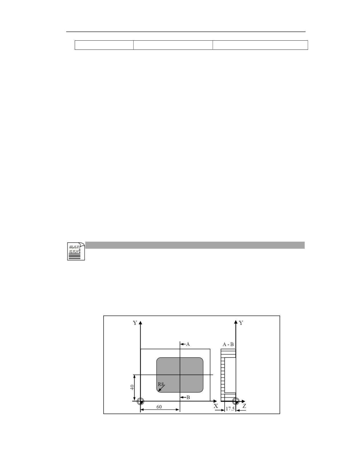
Example
Machine a pocket in the G17 plane with a length of 60mm, a width of 40mm, a corner radius of
8mm, and a depth of 17.5mm. The pocket forms a 0 degree angle with X axis. The finishing
allowance of edge is 0.75mm, and the finishing allowance of bottom is 0.2mm. The pocket center
is X60Y40, the feed depth is 4mm, and the tool radius is 5mm. Only rough machining is
performed, as shown below.
%0526
285
N10 G54 G90 G17
N20 T20
N30 M06
N40 M04 S600
N50 G00 X60 Y40 Z5
N60 G98G184R5Z-17.5K60W40X60Y40I8F120Q4E0.75O0.2D1V5
N70 M30
Note
(1) This cycle requires the use of end mills.
(2) Q and H respectively define the maximum feed depth during roughing and finishing. Note that
when the machining allowance cannot be divisible by Q or H, the last cut will be smaller than Q and
H;
(3) N, K, W, I, E, O, Q, H are input as non-negative numbers. If the input is negative, the negative
sign will be ignored in the cycle;
(4) Please refer to Section 16.4.9 for alarms generated by this cycle;
(5) If the input pocket width is greater than the pocket length, the cycle will automatically exchange
them to the expected position;
(6) The C specified the milling direction such as G182.
(7) The spindle rotation must be specified before entering cycle.
286
16.4.5 Circular Pocket Milling Cycle (G185)
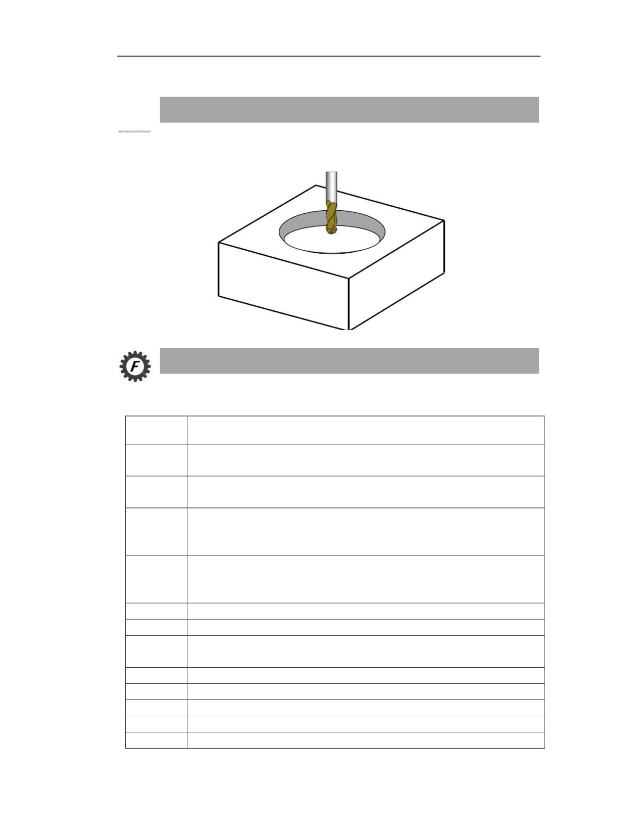
Function and Purpose
This cycle is used for processing circular pocket. Finishing and roughing are supported.
Command Format
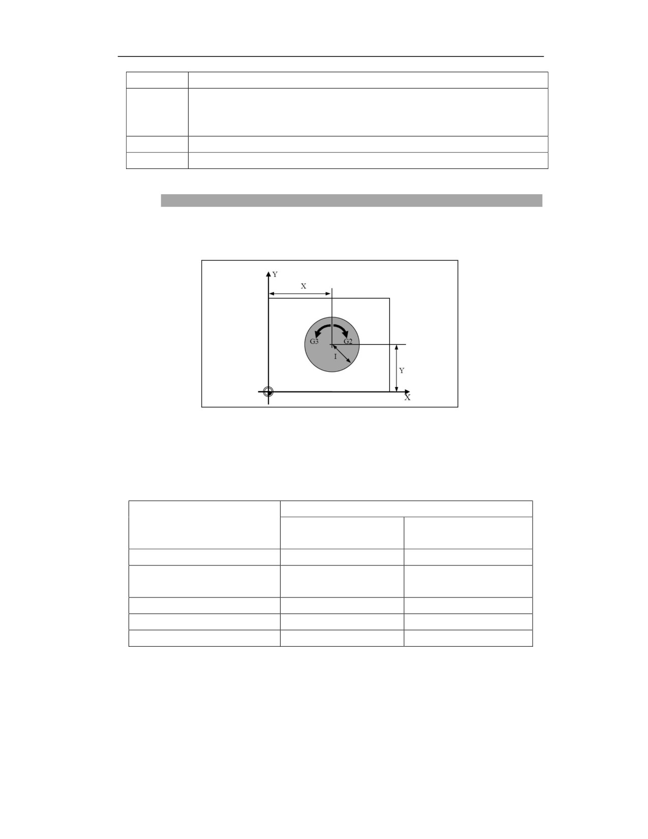
(G98/G99)G185R_Z_X_Y_I_ F_ Q_E_O_H_U_P_C_D_V_;
Parameter
Meaning
Coordinates of R point in absolute programming; distance from reference point B to R
R
point in incremental programming
Coordinate value of pocket bottom in absolute programming; incremental value of
Z
pocket bottom relative to reference point R in incremental programming
Center of pocket. Coordinate of the first axis in the current plane in absolute
X
programming; incremental value relative to the starting point in incremental
programming.
Center of pocket. Coordinate of the second axis in the current plane in absolute
Y
programming; incremental value relative to the starting point in incremental
programming.
I
Radius of pocket
F
Milling speed in roughing
Max. feed depth in roughing (can be omitted when Q=pocket depth-finishing allowance
Q
of pocket bottom)
E
Finishing allowance of pocket edge (can be omitted when E=0)
O
Finishing allowance of pocket bottom (can be omitted when O=0)
H
Max. feed depth in finishing (can be omitted when H=Q)
U
Feedrate in finishing (can be omitted when U=F)
P
Spindle speed in finishing (can be omitted when P=spindle speed or default speed before
287
entering cycle)
Milling direction (can be omitted when C=3)
C
0:milling in the same direction; 1: milling in the reverse direction; 2: milling in G02
direction; 3: milling in G03 direction
D
Machining type (can be omitted when D=1) 1: roughing; 2: finishing
V
Tool radius
Description
Graphical representation
Milling direction
The spindle must be specified to rotate before entering the cycle. A reasonable milling direction
is calculated based on the spindle rotation direction M3/4 and the milling direction set by the user
before entering the cycle. The selection of the milling direction is shown in the following table:
Specify M03/M04 before entering cycle
Milling direction (cycle
M03 spindle rotation
M04 spindle rotation
parameter C)
CW
CCW
0: milling in the same direction
G03
G02
1: milling in the reverse
G02
G03
direction
2: G02 direction
G02
G02
3: G03 direction
G03
G03
Omitted
G03
G03
Steps
(1) Selecting a position as the starting position of the cycle, this position can be random, and it must
be possible to reach to workpiece from this position without collision.
(2) Roughing(D=1)
288
Move to the reference level above the edge of pocket with G00 (leaving finishing allowance of the
edge), feed the amount Q, mill the pocket surface from outside to inside based on the milling direction
specified by C, return to the same point and mill the surface again to the finishing allowance at the
bottom of the pocket.
(3) Finishing(D=2)
Move to the reference level above the edge of pocket with G00 (leaving finishing allowance of the
edge), feed the amount H, mill the fillishing allowance from outside to inside based on the milling
direction specified by C, and return to the same point and mill the surface again to the finishing
allowance at the bottom of the pocket. Then mill the fillishing allowance of bottom from outside to
inside based on the milling direction specified by C
(4) After the pocket is machined, move the tool to the initial level or reference level with G98/G99,
and the cycle is completed.
Example
Mill a circular pocket. The center is X50 Y50, the radius is 100mm, the pocket depth is 50mm, the
finishing allowance of the pocket bottom and the pocket edge are 2mm and 1.5mm respectively, the
roughing depth is 4mm, and the tool radius is 5mm.
%1022
G54 X0 Y0 Z40
G17 G90
T10
M06
M03 S650
G99 G185 R0 Z-50 X50 Y50 I100 F300 Q4 E1.5 O2 V5D1; Roughing
X50 Y50 I100 P800 H1.5 D2; Finishing
M30
Notes
(1) Please refer to section 16.4.9 for the alarms generated in this cycle;
(2) Q and H are the maximum feed depths for roughing and finishing respectively. Note that when
the feed allowance cannot be divisible by Q or H, the last cut will be less than Q or H;
(3) I, E, O, Q, and H are specified as non-negative numbers. If a negative number is specified, the
negative sign will be ignored in the cycle;
(4) C specifies the milling direction such as G182;
(5) The spindle rotation must be specified before entering cycle.
289

16.4.6 End Face Milling Cycle(G186)
Function and Purpose
This cycle can mill any rectangular end face in finishing and roughing.
Command Format
(G98/G99)G186R_Z_N_W_X_Y_ I_ A_F_Q_J_O_H_K_U_P_C_D_V_
Parameter
Meaning
Coordinates of reference point R in absolute programming; distance from initial level B
R
to R point in incremental programming
Coordinate value of bottom in absolute programming; incremental value of bottom
Z
relative to reference point R in incremental programming
N
Length of the first axis of workpiece
W
Length of the second axis of workpiece
Starting position.
X、Y
Coordinate of the first axis in the current plane in absolute programming; incremental
value relative to the current point in incremental programming.
I
Safety margin in milling direction (can be omitted, I=tool radius)
The angle between the long side of the end face and the positive direction of the first axis
A
in the plane (can be omitted, A=0)
F
Milling speed in roughing
Max. feed depth in roughing (can be omitted, Q=milling depth-finishing allowance of
Q
bottom)
J
Milling width in roughing (can be omitted, J=tool diameter×80%)
O
Finishing allowance of workpiece bottom (can be omitted, O=0)
H
Max. feed depth in finishing (can be omitted, H=Q)
K
Cutting width in finishing (can be omitted, K=tool diameter×80%)
U
Milling speed in finishing (can be omitted, U=F)
Spindle speed in finishing (can be omitted, P=spindle speed or default speed before
P
entering cycle)
Milling direction (can be omitted, C=0)
0: Bidirectional machining of 1st axis in the selected plane
C
1: Bidirectional machining of 2nd axis in the selected plane
2: Unidirectional machining of 1st axis in the selected plane
3: Unidirectional machining of 2nd axis in the selected plane
Machining type (can be omitted, D=1)
D
1: roughing, 2: finishing
V
Tool radius
290
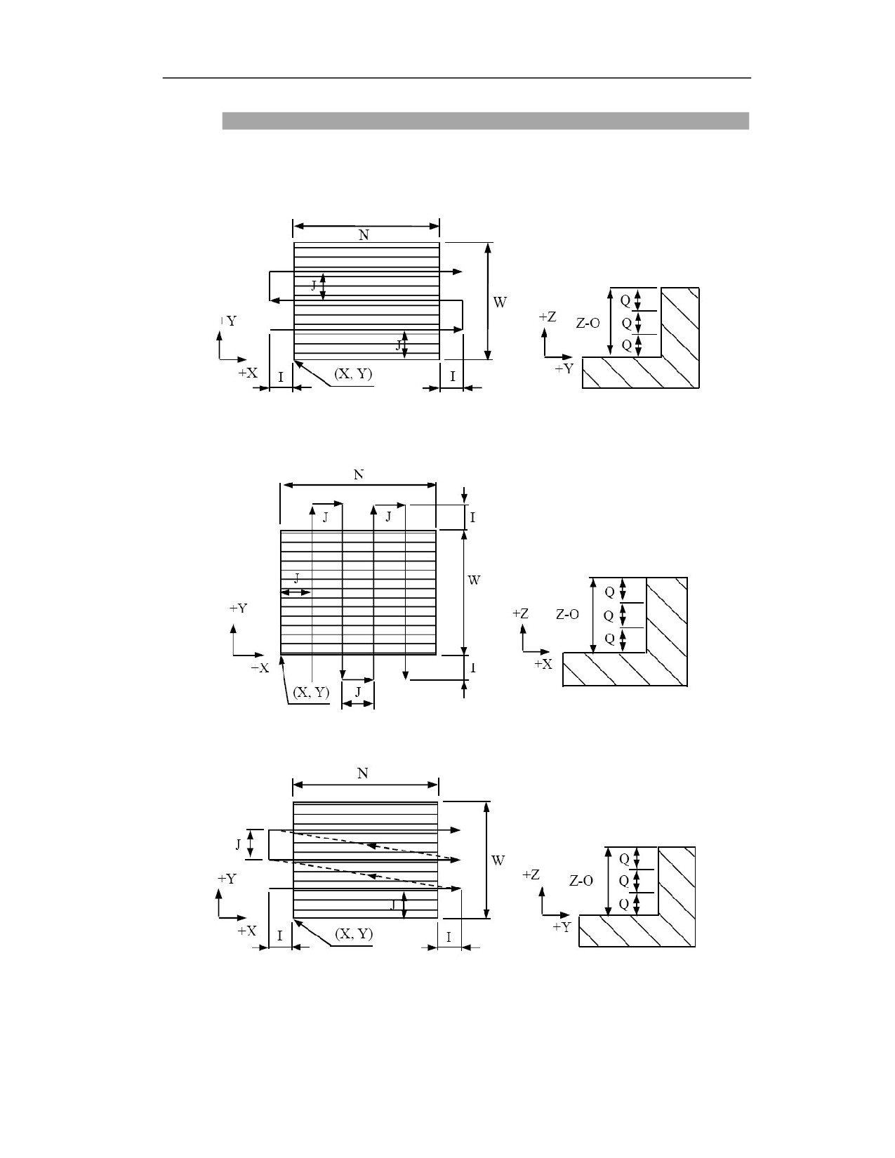
Description
C=0,D=1, bidirectional machining of X axis
C=1,D=1,unidirectional machining of X axis
C=2,D=1,unidirectional machining of X axis
C=3,D=1,unidirectional machining of Y axis
291
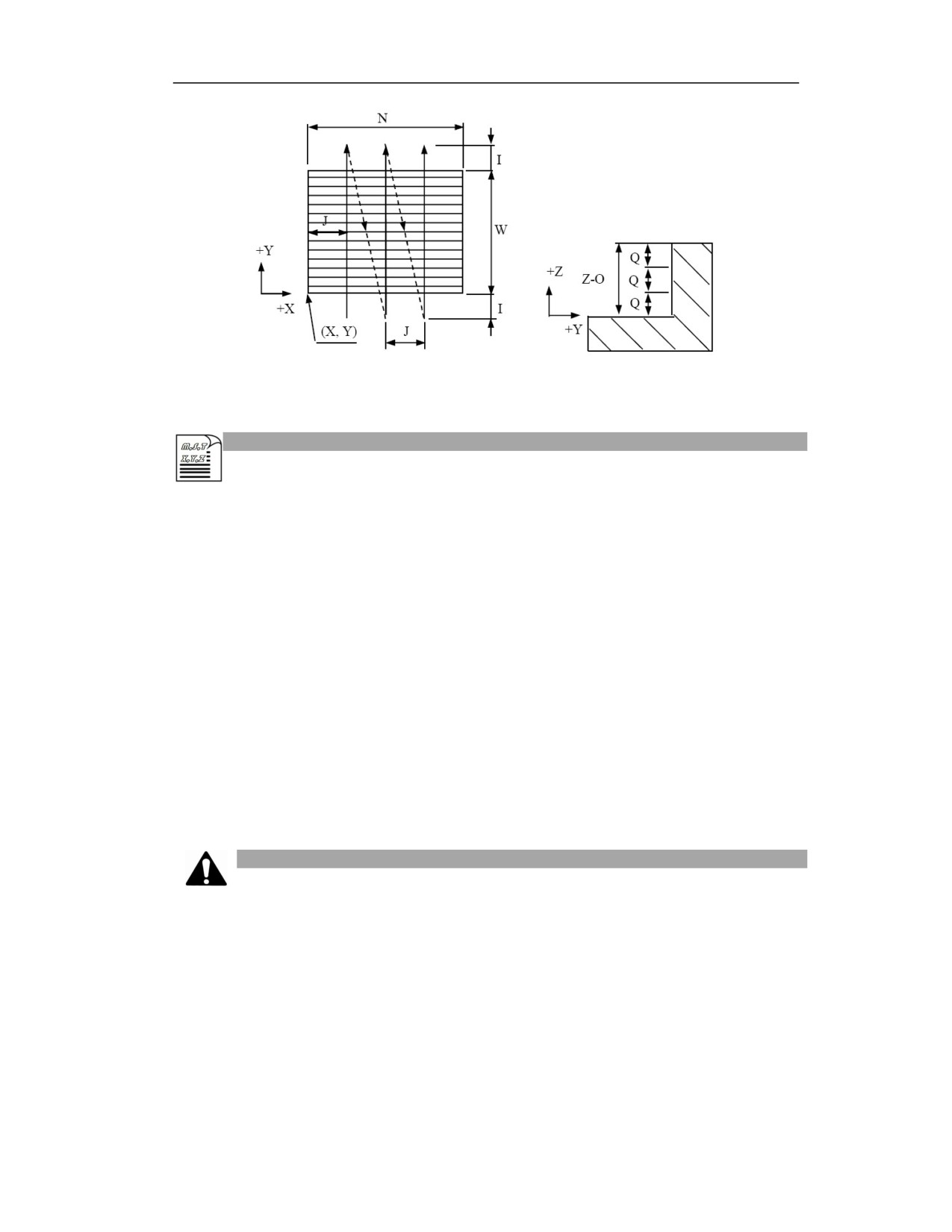
(Note 1) The above table only lists end face milling cycle in G17 plane (rough machining), for
G18/G19 plane and so on, finishing and hybrid machining (D=2) are also similar.
Example
For milling a rectangular end face, the end face dimensions and related process parameters are as
follows:
Initial level 10mm; reference level 2mm, only rough machining is allowed, each milling width
10mm, each feed depth 6mm, total milling depth 11mm, milling starting point (100, 100), end face
size 60mm×40mm, the safety margin in milling direction is 5mm. Bidirectional milling of X axis
is allowed, the processing feedrate of surface is 500mm/min, and the milling tool radius is 5mm.
N10
G54 X0 Y0 Z20
N20
G17 G90
N30
T10
N40
M06
N50
M03 S650
N60
G00 X0 Y0 Z20
N70
G99G186 Z-11 R0 N60 W40 X100 Y100 I5 F500 Q6 J10 V5
N80 M30
Note
1) N, W, I, O, Q, J, H, K are designated as non-negative numbers. If a negative number is input, the
negative sign will be ignored in the cycle;
2) For the feed width (J, K) and feed depth (Q, H), when the feed amount cannot be divisible by it,
the last cut will be smaller than the feed width or depth;
3) The spindle must be commanded to rotate before entering the cycle;
4) Please refer to section 16.4.9 for the alarms generated in this cycle.
292
华中 8 型数控系统编程说明书
16.4.7 Rectangular Boss Milling Cycle (G188)
Function and Purpose
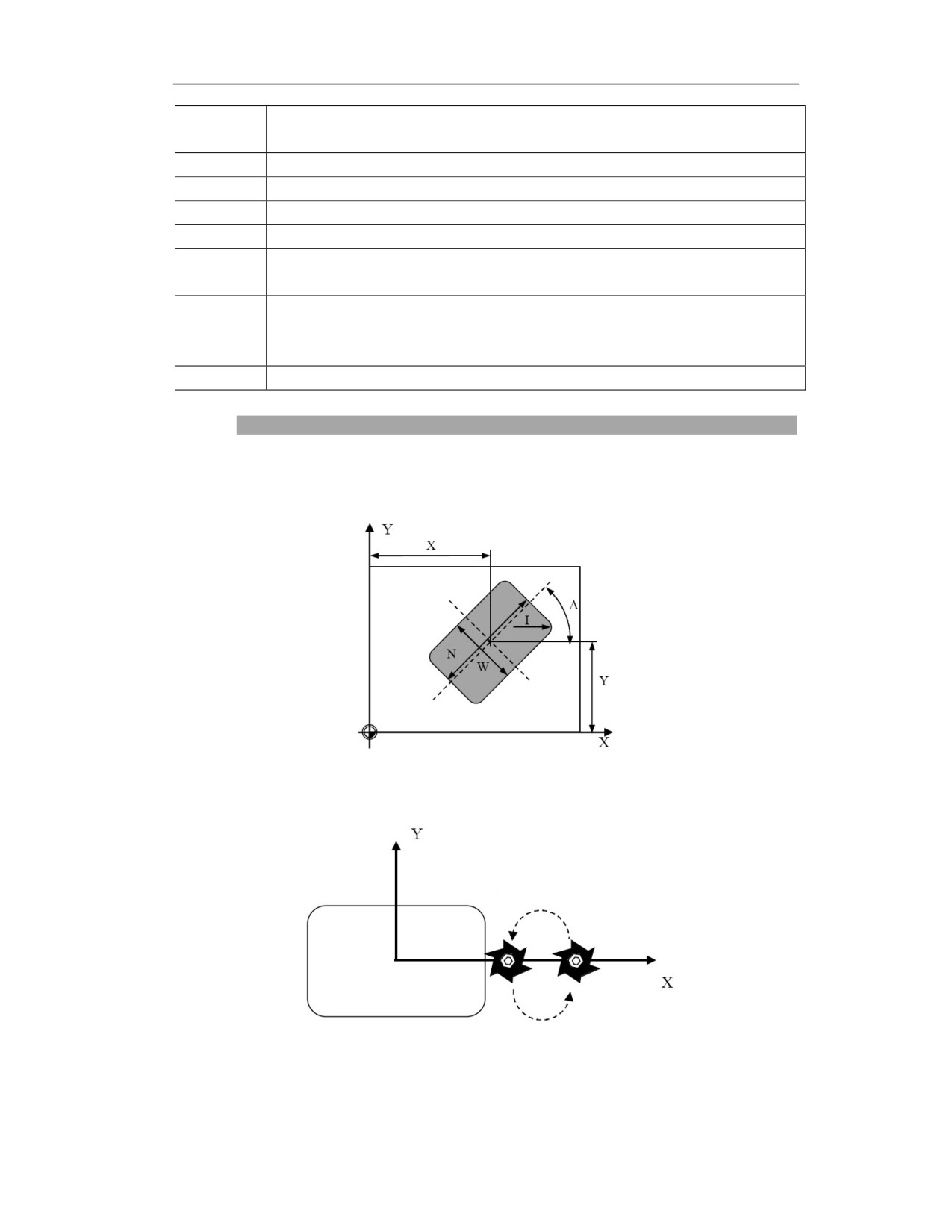
Rectangular boss milling cycle is for processing rectangular bosses of any size in the plane. The
rectangle bosses can have corner arcs. User can choose the type of machining, finishing, rough
machining or hybrid machining.
Command Format
(G98/G99)G188R_Z_N_W_X_Y_J_K_I_ A_F_ Q_E_O_H_U_P_C_D_V_;
Parameter
Meaning
Coordinates of R point in absolute programming; distance from reference point R to
R
initial level in incremental programming
Coordinates of boss bottom in absolute programming; distance from boss bottom to
Z
reference point R in incremental programming
N
Length of boss
W
Width of boss
Center of boss. Coordinate of the first axis in the current plane in absolute programming;
X
incremental value relative to the starting point in incremental programming.
Center of boss. Coordinate of the second axis in the current plane in absolute
Y
programming; incremental value relative to the starting point in incremental
programming.
J
Length of boss blank
K
Width of boss blank
I
Radius of corner of boss (can be omitted, I=W/2)
The angle between the long side of the rectangular boss and the positive direction of the
A
first axis in the plane (can be omitted, A=0)
F
Milling speed in roughing
293
华中 8 型数控系统编程说明书
Max. feed depth in roughing (can be omitted, Q=pocket depth-finishing allowance of
Q
boss bottom)
E
Finishing allowance of boss edge (can be omitted when E=0)
O
Finishing allowance of boss bottom (can be omitted when O=0)
H
Max. feed depth in finishing (can be omitted when H=Q)
U
Feedrate in finishing (can be omitted when U=F)
Spindle speed in finishing (can be omitted when P=spindle speed or default speed before
P
entering cycle)
Milling direction (can be omitted when C=3)
C
0:milling in the same direction; 1: milling in the reverse direction; 2: milling in G02
direction; 3: milling in G03 direction
D
Machining type (can be omitted, D=1) 1: roughing; 2: finishing
Description
Graphical representation
Enter contour, exit contour
Return to the contour
Leave the contour
In order to ensure the smoothness when the tool enters the workpiece, the cycle automatically
adds a semicircle path when entering and exiting the workpiece during execution. The radius is
determined by the cycle parameters, and the direction is opposite to the milling direction. If the
294
华中 8 型数控系统编程说明书
G2 direction is specified for milling, then the semicircle inserted here is in the G3 direction.
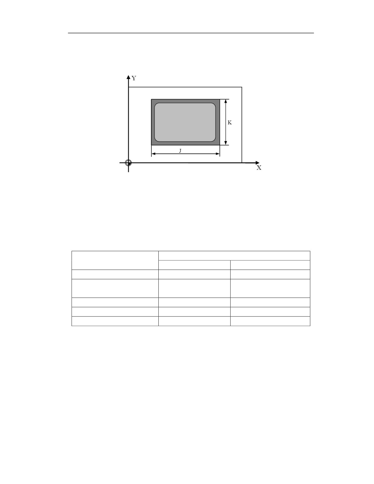
Size of boss blank
For the processing of pre-poured workpieces, the blank size of the rectangular boss can also be
considered, which is symmetrical to the boss size, and the center point is also (X, Y).
Milling direction
The spindle must be specified to rotate before entering the cycle. A reasonable milling direction
is calculated based on the spindle rotation direction M3/4 and the milling direction set by the user
before entering the cycle. The selection of the milling direction is shown in the following table:
Milling direction (cycle
Specify M03/M04 before entering cycle
parameter C)
M03 spindle rotation CW
M04 spindle rotation CCW
0: milling in the same direction
G03
G02
1: milling in the reverse
G02
G03
direction
2: G02 direction
G02
G02
3: G03 direction
G03
G03
Omitted
G03
G03
295
Steps
(1) Select a position as the starting position of the cycle. This point needs to be positioned on the
right side of the boss in the positive direction of the first axis in the plane. Note that the semicircle
automatically added needs to be taken into account.
(2) Roughing(D=1)
Move to the reference level above the wide side of the boss with G00, feed an amount, mill the
blank surface to the finishing allowance of the edge based on the milling direction, exit the
workpiece contour, rapid traverse to the starting point with G00, and feed to machine the surface
of boss to the finishing allowance of the bottom.
(3) Finishing(D=2)
Move to the reference level above the wide side of the boss with G00, feed an amount, enter the
workpiece contour to mill the finishing allowance of the edge based on the milling direction, exit
the workpiece contour, rapid traverse to the starting point with G00, and then feed to machine the
mill the bottom to the finishing allowance; and mill the finsihing allowance of the bottom.
(4) After the boss is machined, move the tool to the initial level or reference level with G98/G99,
and the cycle is completed.
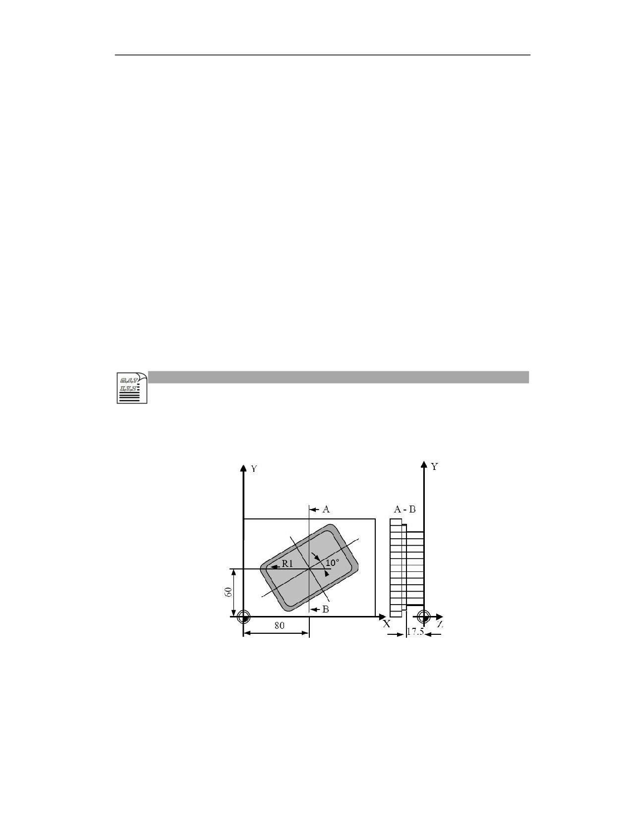
Example
Machine the rectangular boss as shown in the figure below, the boss size is 60mm×40mm, the
blank size is 80mm×50mm, and the tool radius is 3mm.
%1019
G17 G54 G90
T10
M06
M03 S650
G98 G188 R2Z-17.5N60W40X80Y60J80K50I15A10F200Q11E2O1V3
296
M30
Note
(1) Please refer to section 16.4.9 for the alarms generated in this cycle;
(2) W, J, K, I, E, O, Q, H are designated as non-negative numbers. If a negative number is specified,
the negative sign will be ignored in the cycle;
(3) The maximum feed depth of finishing and roughing is specified with Q and H respectively.
When the feed amount cannot be divisible by it, the last cut will be smaller than Q or H;
(4) The spindle must be commanded to rotate before entering the cycle;
(6) If the specified wide side is greater than the long side, the wide side and the long side will be
automatically exchanged by the cycle, and the corresponding rotation will be performed to meet
the desired boss position.
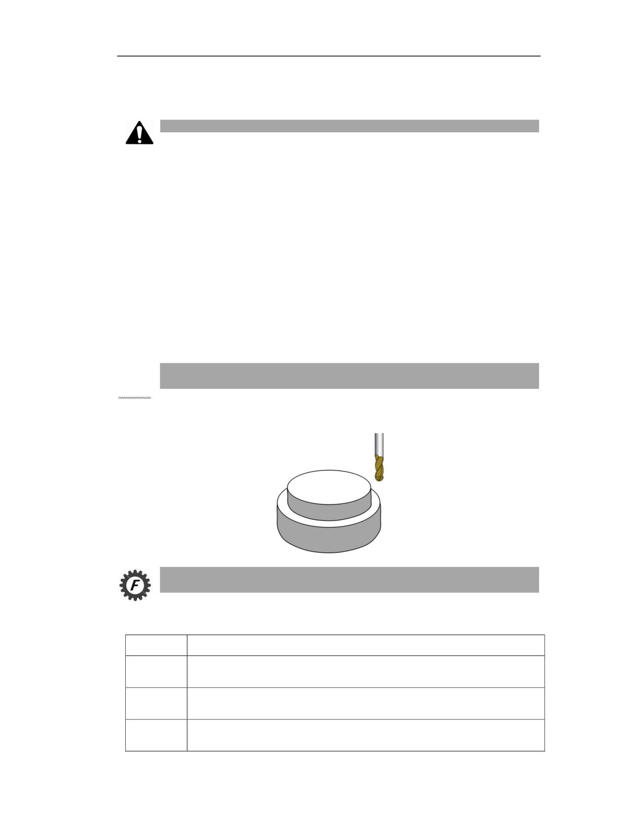
16.4.8 Round Boss Milling Cycle (G189)
Function and Purpose
This cycle is to machine the round boss of any size in the plane.
Command Format
(G98/G99)G189R_Z_X_Y_ I_ J_F_ Q_E_O_H_U_P_C_D_V_;
Parameter
Meaning
Coordinates of R point in absolute programming; distance from reference point R to
R
initial level in incremental programming
Coordinates of boss bottom in absolute programming; incremental value of boss bottom
Z
relative to reference point R in incremental programming
Center of boss. Coordinate of the first axis in the current plane in absolute programming;
X
incremental value relative to the starting point in incremental programming.
297
Center of boss. Coordinate of the second axis in the current plane in absolute
Y
programming; incremental value relative to the starting point in incremental
programming.
I
Radius of round boss
J
Radius of blank
F
Milling speed in roughing
Q
Max. feed depth in roughing (can be omitted)
E
Finishing allowance of boss edge (can be omitted, E=0)
O
Finishing allowance of boss bottom (can be omitted, O=0)
H
Max. feed depth in finishing (can be omitted, H=Q)
U
Feedrate in finishing (can be omitted, U=F)
Spindle speed in finishing (can be omitted, P=spindle speed or default speed before
P
entering cycle)
Milling direction (can be omitted, C=3)
C
0:milling in the same direction; 1: milling in the reverse direction; 2: milling in G02
direction; 3: milling in G03 direction
D
Machining type (can be omitted, D=1) 1: roughing; 2: finishing
V
Tool radius
Description
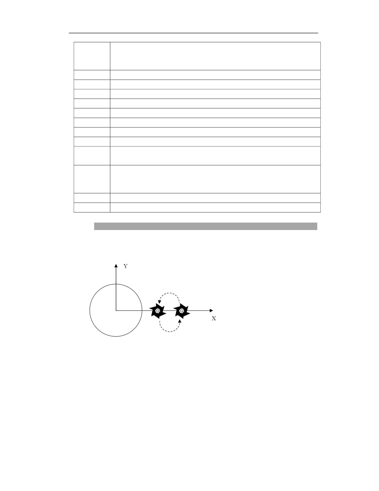
Enter contour, exit contour
Return to the contour
Leave the contour
Like the G188 cycle, this cycle also adds a semi-circle every time the tool horizontally enters or exits
the blank workpiece to ensure the smooth transition of the moving from boss edge to the blank, and
the radius of the semi-circle is automatically calculated by the cycle.
Blank size
Like the G188 cycle, this cycle can also set the size of the blank, and the center point is also (X, Y).
Milling direction
The spindle must be specified to rotate before entering the cycle. A reasonable milling direction is
calculated based on the spindle rotation direction M3/4 and the milling direction set by the user
before entering the cycle. The selection of the milling direction is shown in the following table:
298
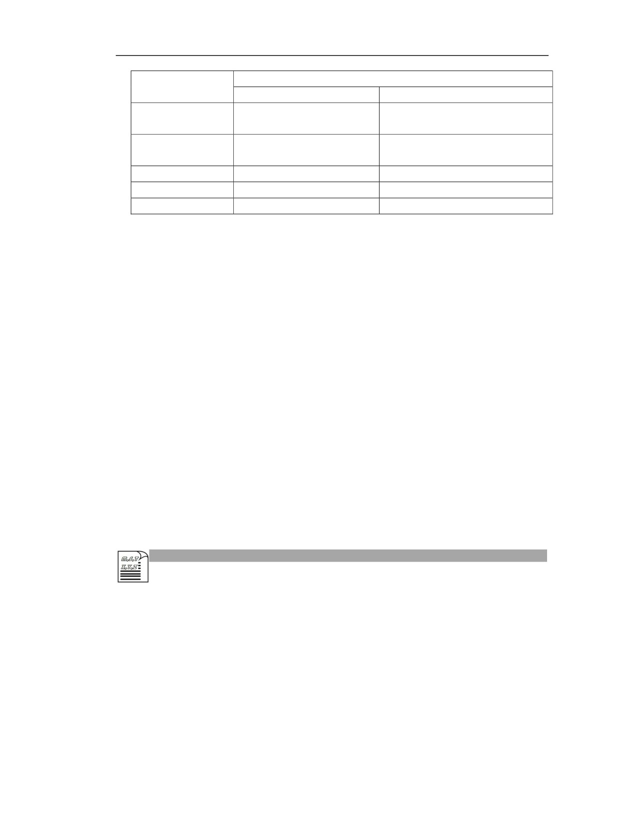
Milling direction
Specify M03/M04 before entering cycle
(cycle parameter C)
M03 spindle rotation CW
M04 spindle rotation CCW
0: milling in the
G03
G02
same direction
1: milling in the
G02
G03
reverse direction
2: G02 direction
G02
G02
3: G03 direction
G03
G03
Omitted
G03
G03
Steps
(1) Select a position as the starting position of the cycle. This point needs to be positioned on the
right side of the boss in the positive direction of the first axis in the plane. Note that the semicircle
automatically added by the cycle needs to be taken into account.
(2) Roughing(D=1)
Move to the reference level above the wide side of the boss with G00, feed an amount, mill the blank
surface to the finishing allowance of the edge based on the milling direction, exit the workpiece
contour, rapid traverse to the starting point with G00, and feed to machine the surface of boss to the
finishing allowance of the bottom.
(3) Finishing(D=2)
Move to the reference level above the wide side of the boss with G00, feed an amount, enter the
workpiece contour to mill the finishing allowance of the edge based on the milling direction, exit the
workpiece contour, rapid traverse to the starting point with G00, and then feed to machine the mill
the bottom to the finishing allowance; and mill the finsihing allowance of the bottom.
(4) After the boss is machined, move the tool to the initial level or reference level with G98/G99, and
the cycle is completed.
Example
Machine the round boss as shown in the figure below, the blank radius is 55mm, the feed depth for
each cut is 10mm, and the tool radius is 5mm.
299
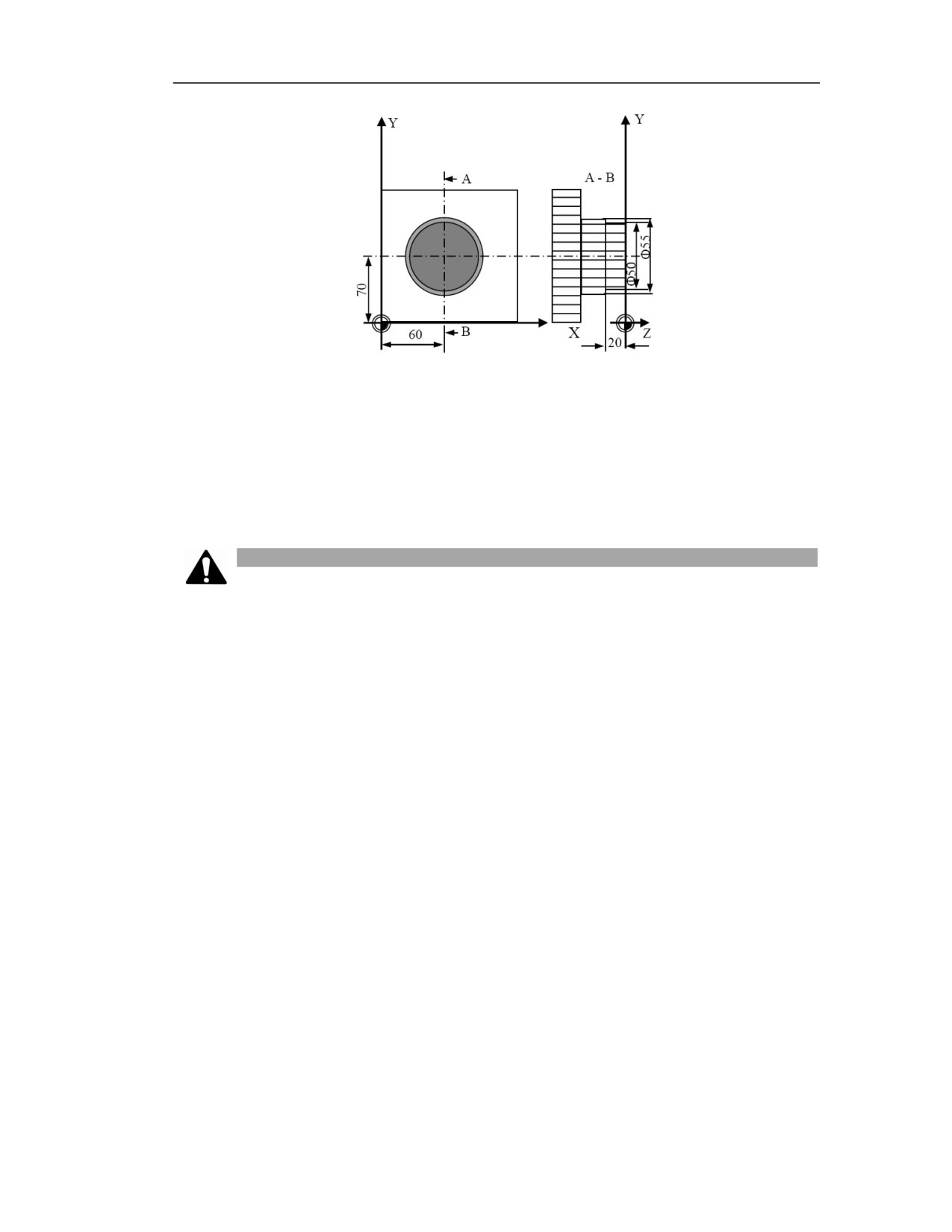
%1020
G17 G54 G90
T10
M06
M03 S650
G98G189 R2Z-20X60Y70I25J27.5F200Q10E1O1V5
M30
Note
(1) Please refer to section 16.4.9 for the alarms generated in this cycle.
(2) J, K, I, E, O, Q, H are designated as non-negative numbers. If a negative number is specified, the
negative sign will be ignored in the cycle.
(3) The maximum feed depth for roughing and finishing is specified with Q and H respectively, when
the feed amount cannot be divisible by it, the last cut will be smaller than Q or H;
(4) The spindle must be commanded to rotate before entering the cycle;
300

16.4.9 Milling Cycle Alarm Diagnosis
Function and Purpose
When the milling canned cycle is executed, if the system recognizes an error, an alarm will be
generated and the execution of the current cycle will be interrupted. It will continue after modified
by user.
This section lists the possible alarms that the system may generate during the execution of the
milling cycle, and analyzes the cause of the alarms. User can modify the program based on that
before continuing to execute the cycle.
Description
Alarm No.
Message
Source
Cause and comments
G181
G182
G183
G184
No tool radius V is specified before
800
No tool radius defined
G185
entering cycle.
G186
G188
G189
If R is not specified in this block, and
G181
the R modal value cannot be detected
G182
by the cycle, this alarm will be
G183
generated.
No reference level
G184
801
This parameter is required to specify
defined
G185
the groove depth in increments or
G186
when returning to the R level at the
G188
end of the cycle, so this parameter
G189
should be defined.
G181
G182
G183
The position of groove bottom needs
No groove
bottom
G184
to be defined, otherwise the groove
802
position defined
G185
depth cannot be determined in the
G186
cycle.
G188
G189
G181
If the number of grooves is specified
Number of grooves
803
G182
as 0, an alarm will be generated. The
defined as zero
G183
number of grooves should be specified
301

as an integer larger than 0.
The groove length must be greater
Groove lenth defined too
804
G182
than the groove width, otherwise this
small
alarm will be generated.
G181
G182
If the diameter of the milling cutter
G183
exceeds the groove length defined by
G184
805
Tool radius too large
the cycle, this alarm will be generated.
G185
User can use a milling cutter with a
G186
smaller radius to complete the milling.
G188
G189
If the arc center position is not
G181
No center position
explained in the block, and the cycle
806
G182
defined
fails to detect the modal position, this
G183
alarm will be generated.
If there is no arc radius modal value,
G181
the radius value must be specified in
807
No radius defined
G182
this row, otherwise this alarm will be
G183
generated.
Considering the angle between the
milling cutter radius and
the
grooves, there may be interference
G181
Interference
between
between the machined grooves, which
808
G182
grooves
will affect the contour shape of the
G183
groove. The interference check will be
performed before the cycle, and user
will be prompted in time.
。Due to the improper definition of the
number of grooves and the angle
Number of grooves
G181
between grooves, this alarm will be
809
conflicts
with angle
G182
generated if the number of grooves
increment defined
G183
×angle between grooves>
360
degrees.
G181
G182
G183
The alarm is generated when the
Max. feed depth defined
G184
maximum feed depth Q is greater than
810
too large
G185
the groove depth. If this alarm occurs,
G186
reduce Q.
G188
G189
811
Please command spindle
G181
Before the cycle is executed, the
302

to rotate before entering
G182
current spindle status is detected. This
cycle
G183
alarm will be generated if the spindle
G184
is not rotating.
G185
G186
G188
G189
G184
Center
position
not
If the position of circular pocket center
G185
812
defined
for
circular
or boss center is not defined, this
G188
pocket or boss
alarm will be generated.
G189
Radius position not
If the radius of round pocket or boss is
G185
813
defined
for
circular
not defined, this alarm will be
G189
pocket or boss
generated.
G182
G183
The reserved edge finishing allowance
Finishing allowance of
G184
814
is too large to complete the machining.
edge too large
G185
Please reduce the allowance.
G188
G189
G182
G183
The reserved finishing allowance of
G184
Finishing allowance of
edge is too large to complete the
815
G185
bottom too large
machining. Please reduce the
G186
allowance.
G188
G189
G182
G183
Max.feed
depth
in
G184
When the maximum feed depth H is
816
finishing defined too
G185
larger than the groove depth, this
large
G186
alarm is generated, then reduce H.
G188
G189
For G186, the end face size of the
workpiece to be processed must be
Size of workpiece to be
819
G186
specified, such as the length and the
machined not defined
width, otherwise this alarm will be
issued.
It is necessary to specify the starting
No milling starting
point of milling for face milling cycle
820
G186
position defined
G186, which is generally the lower
left corner of the workpiece in
303

machining plane. If it is not specified,
this alarm will be generated.
A safety margin must be specified for
Safety margin defined too
the face milling cycle for a good
821
G186
small
milling effect, and this value is not less
than the milling tool radius.
The milling width is not larger than
Milling width defined too
822
G186
tool diameter in roughing for face
large in roughing
milling cycle G186.
The milling width is not larger than
Milling width defined too
823
G186
tool diameter in finishing for face
large in finishing
milling cycle G186.
For round boss G189 or rectangular
No blank size defined for
G188
boss G188, the blank size needs to be
824
boss
G189
defined, otherwise this alarm will be
generated.
G181
If the groove length or width is not
G182
specified in this block, and the modal
No length or width
826
G183
value of the groove length is not
defined for pocket or boss
G184
detected by the cycle, this alarm will
G188
be generated.
The circular corner can be defined for
Corner radius defined too
the rectangular groove or rectangular
G184
829
large for rectangular
boss cycle, but it cannot be greater
G188
pocket and boss
than the half of the wide side,
otherwise this alarm will be generated.
For round boss G189 or rectangular
Blank
size
defined
G188
boss G188, the blank size must be
830
smaller than machining
G189
larger than the contour size, otherwise
size
this alarm will be generated.
G181
G182
V represents the compensation
G183
number in the tool compensation
Tool radius cannot be
G184
table. The value filled in the
873
zero
G185
compensation number is the tool
G186
radius. This value cannot be zero,
G188
otherwise this alarm will be generated.
G189
G182
During finishing machining, the
G183
finishing allowance of groove wall
No finishing allowance
874
G184
and the finishing allowance of groove
defined
G185
bottom cannot be unspecified or
G186
specified as
0 at the same time,
304

G188
otherwise this alarm will be generated.
G189
G182
G183
C sets a value other than 0, 1, 2, and 3.
G184
Milling
direction
If a milling direction not supported by
817
G185
definition error
the system is defined, this alarm will
G186
be issued.
G188
G189
G182
G183
D sets a value other than 1 and 2. If a
G184
Machining
type
milling direction not supported by the
818
G185
definition error
system is defined, this alarm will be
G186
issued.
G188
G189
305
17 Multiple Repetitive Cycle in Lathe(T)
This kind of canned cycle can simplify programming, and describe the tool path of roughing using
the shape data of finishing. The system provides four multiple repetitive cycles for users:
G71: Inner (outer) diameter roughing multiple repetitive cycle
G72: End face roughing multiple repetitive cycle
G73: Closed contour multiple repetitive cycle
G76: Thread cutting multiple repetitive cycle
Using multiple repetitive cycle commands, users only need to specify the finishing path and the
feed amount of roughing, and the system will automatically calculate the roughing path and the
number of cuttings.
Note
1. The cycles described in this chapter are only for lathe system.
2. For the multiple repetitive cycle of G71, G72, G73, please note the following:
The block designated by address P should have G00 or G01 command of group 01,
otherwise an alarm will be generated;
The multiple repetitive cycle cannot run in MDI.
In the multiple repetitive cycles G71, G72, G73, the block where the sequence
number designated by P, Q should not include M98 subprogram call or M99
subprogram return command;
In the multiple repetitive cycles G71, G72, G73, the tool compensation can be
performed only in the blocks of which sequence numbers designated by P and Q.
17.1
Inner (Outer) Diameter Roughing Multiple Repetitive Cycle (G71)
306
Function and Purpose
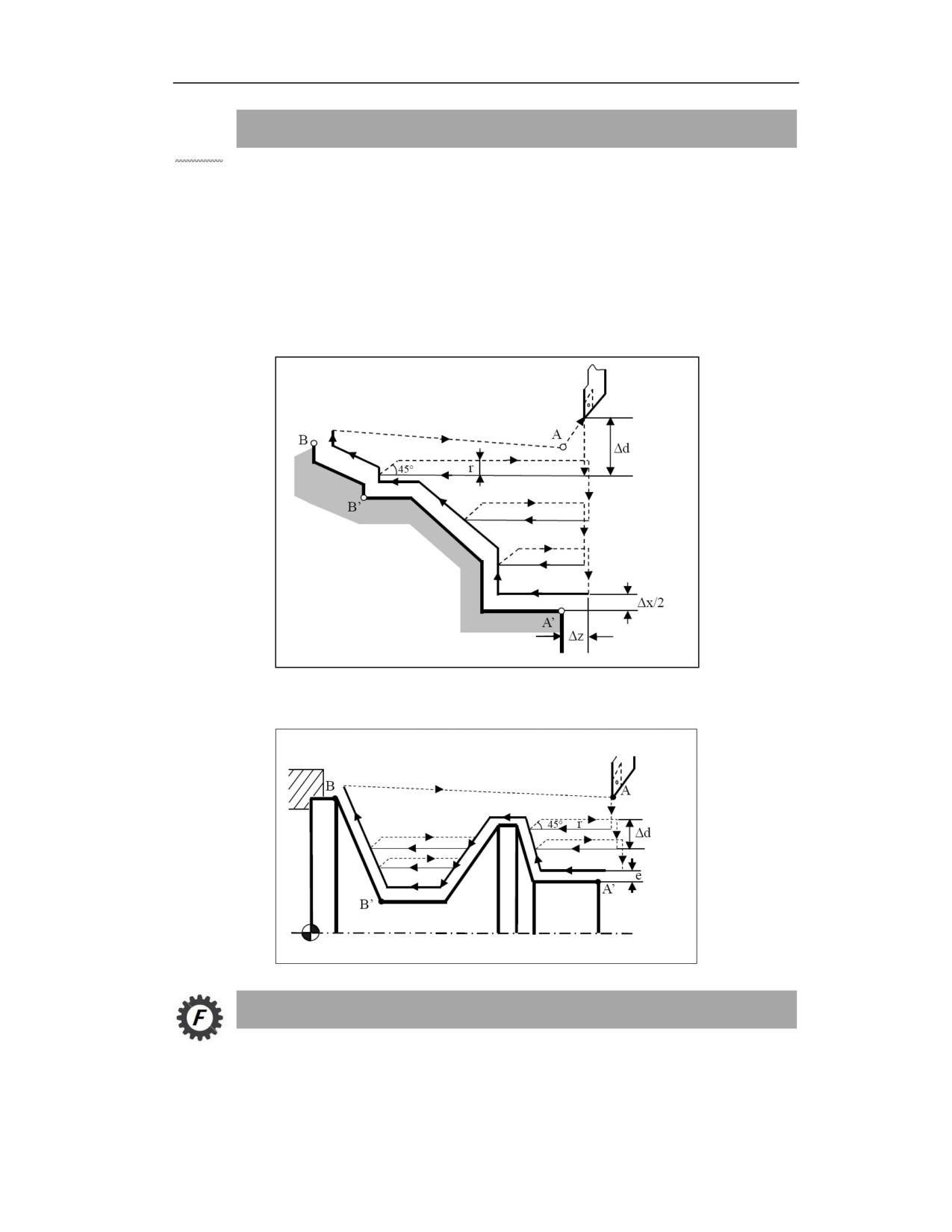
This cycle includes the inner (outer) diameter roughing multiple repetitive cycle with pocket and
without pocket.
This command executes rough machining as shown in the figure below, and the tool returns to
the starting point of the cycle. The finishing path A→A'→B'→B is executed sequentially based
on the following commands.
1. Path of inner/outer diameter roughing multiple repetitive cycle without pocket
2. Path of inner/outer diameter roughing multiple repetitive cycle with pocket
Command Format
1. Inner/outer diameter roughing multiple repetitive cycle without pocket
G71 U(d) R(r) P(ns) Q(nf) X(x) Z(z) F(f) S(s) T(t)
307
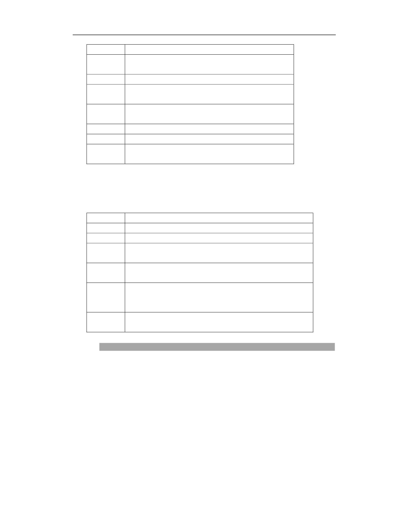
Parameter
Meaning
U
Cutting depth, without sign. The direction is determined by vector
AA′
R
Retraction amount
P
Sequence number of the first program block (AA' in the below
figure) for finishing path
Q
Sequence number of the last program block (BB' in the below
figure) for finishing path
X
Finishing allowance in X direction
Z
Finishing allowance in Z direction
FS T
F, S, T in G71 are valid in roughing, and F, S, T between block ns
and nf are valid in finishing
2. Inner/outer diameter roughing multiple repetitive cycle with pocket
G71 U(d) R(r) P(ns) Q(nf) E(e) F(f) S(s) T(t)
Parameter
Meaning
U
Cutting depth, without sign. The direction is determined by vector AA′
R
Retraction amount
P
Sequence number of the first program block (AA' in the below figure) for
finishing path
Q
Sequence number of the last program block (BB' in the below figure) for
finishing path
E
Finishing allowancewhich is the equal height distance in the X direction;
positive for outer diameter cutting, and negative for inner diameter
cutting
F S T
F, S, T in G71 are valid in roughing, and F, S, T between block ns and nf
are valid in finishing
Description
In the G71 cutting cycle, the cutting feed direction is parallel to the Z axis, so it is suitable for the
inner and outer diameter cutting along the axial direction.
This cycle is a rough machining cycle. It is necessary to reserve an appropriate allowance for
subsequent finishing. The finishing allowance in the X\Z axis direction is X(x) and Z(z), x
is the allowance on X, z is the allowance on Z.
Since the direction of the allowance is determined by the programmer based on the processing
technology, the system determines the direction of the feed according to the direction of the
finishing allowance set by the program. The direction of the finishing allowance (positive and
negative settings) must be correct, otherwise it will cause an error in the feed direction of the tool.
308
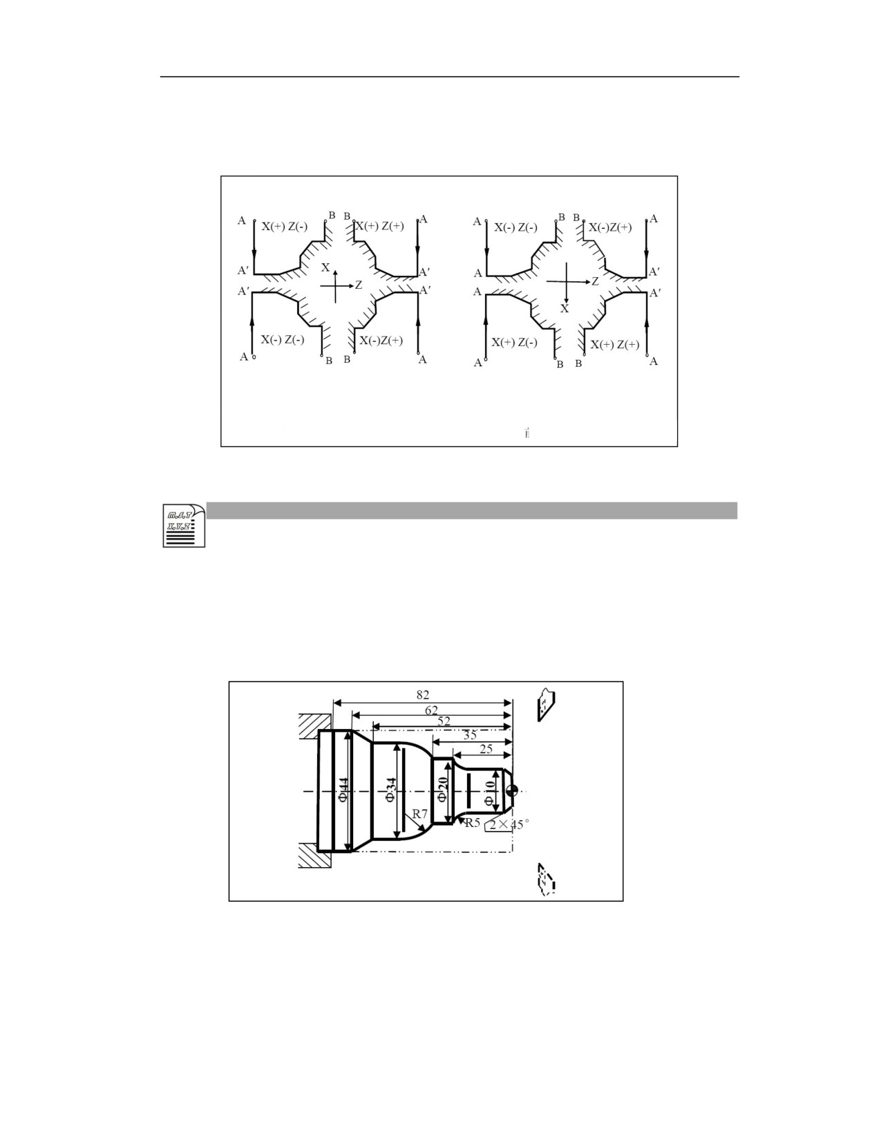
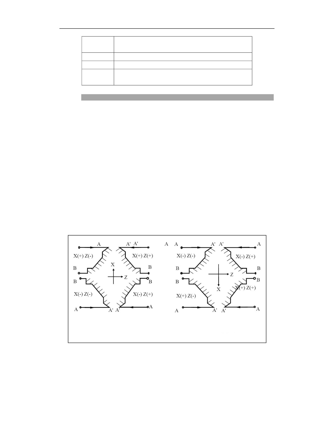
The relationship between the sign of the finishing allowance and the feed direction is shown in
the figure below. (+) means that the contour allowance is kept in the positive direction of the axis,
and (-) means that the contour allowance is kept in the negative direction of the axis.
Machine tool with rear tool post
Machine tool with front tool post
Example
Example 1: Use the outer diameter roughing multiple repetitive cycle to compile the machining
program of the part shown in the figure below: the starting point of the cycle is required to be A
(46, 3), and the cutting depth is 1.5mm (radius), the retraction amount is 1mm, the finishing
allowance in the X direction is 0.4mm, and the finishing allowance in the Z direction is 0.1mm.
The dotted line is the workpiece blank.
%3325
T0101; Set coordinate system, select No.1 tool
N1 G00 X80 Z80; Move to starting point of program
N2 M03 S400; Spindle rotates CW at 400r/min
309
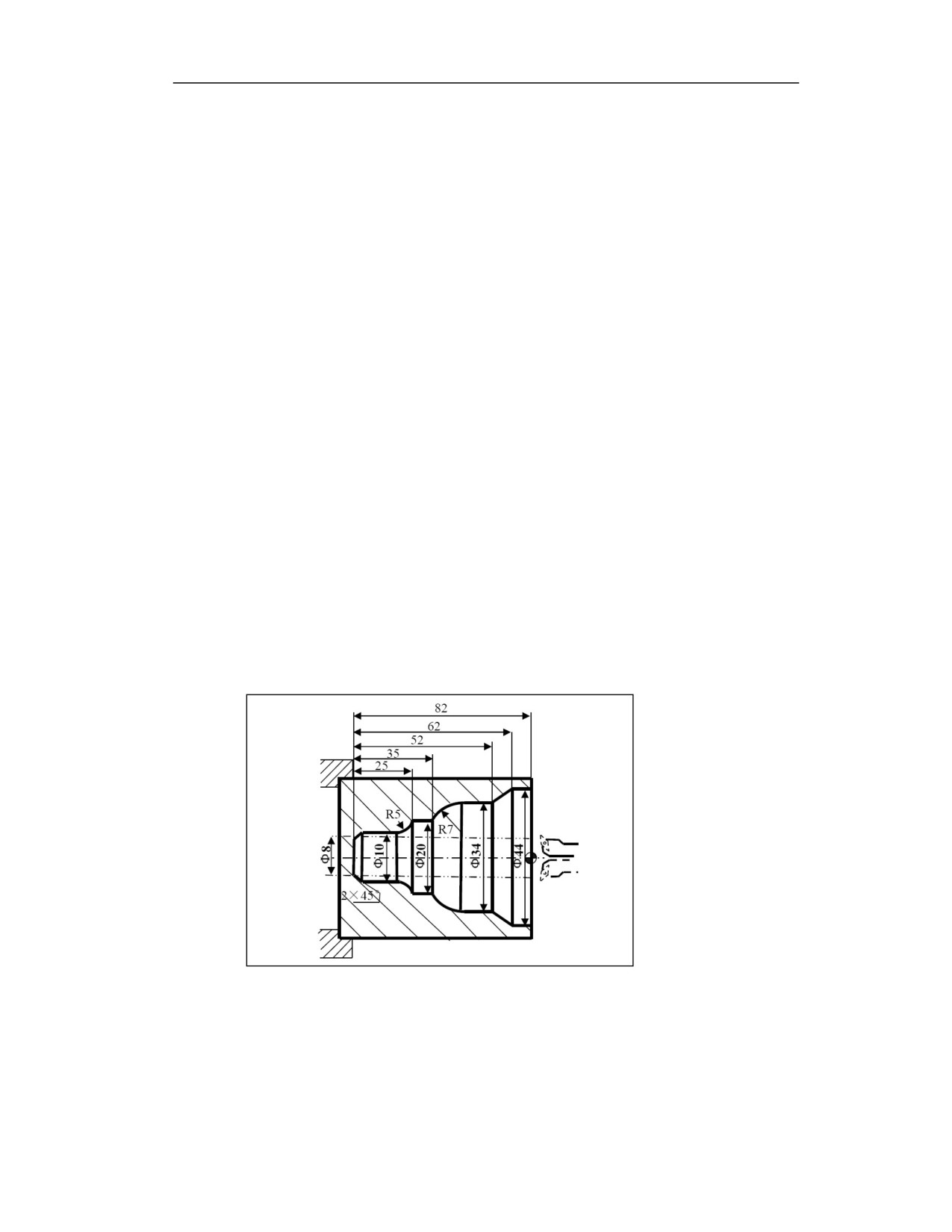
N3 G01 X46 Z3 F100; Move to starting point of cycle
N4 G71U1.5R1P5Q14X0.4 Z0.1; Rough cut:1.5mm Finish cut:X0.4mm Z0.1mm
N5 G00 X0; Finishing contour starts, move to extension line of chamfer
N6 G01 X10 Z-2 ; Finishing 2×45°chamfer
N7 Z-20; Finishing Φ10 outer circle
N8 G02 U10 W-5 R5; Finishing R5 arc
N9 G01 W-10; Finishing Φ20 outer circle
N10 G03 U14 W-7 R7; Finishing R7 arc
N11 G01 Z-52; Finishing Φ34 outer circle
N12 U10 W-10; Finishing outer cone
N13 W-20; Finishing Φ44 outer circle
N14 U1; Finishing contour end
N15 X50; Exit the machined surface
N16G00 X80 Z80; Return to tool setting point
N17 M05; Spindle stop
N18 M30; Main program end and reset
Example 2: Use the inner diameter roughing multiple repetitive cycle to compile the processing
program of the part shown in the figure below: the starting point of the cycle is required to be A
(6, 5), and the cutting depth is 1.5mm (radius). The retraction amount is 1mm, the finishing
allowance in the X direction is 0.4mm, and the finishing allowance in the Z direction is 0.1mm.
The dotted line is the workpiece blank.
%3326
N1 T0101; Select No. 1 tool, and determine the coordinate system
N2 G00 X80 Z80; Move to starting point of program or the tool change position
N3 M03 S400; Spindle rotates CW at 400r/min
N4 X6 Z5; Move to starting point of cycle
310
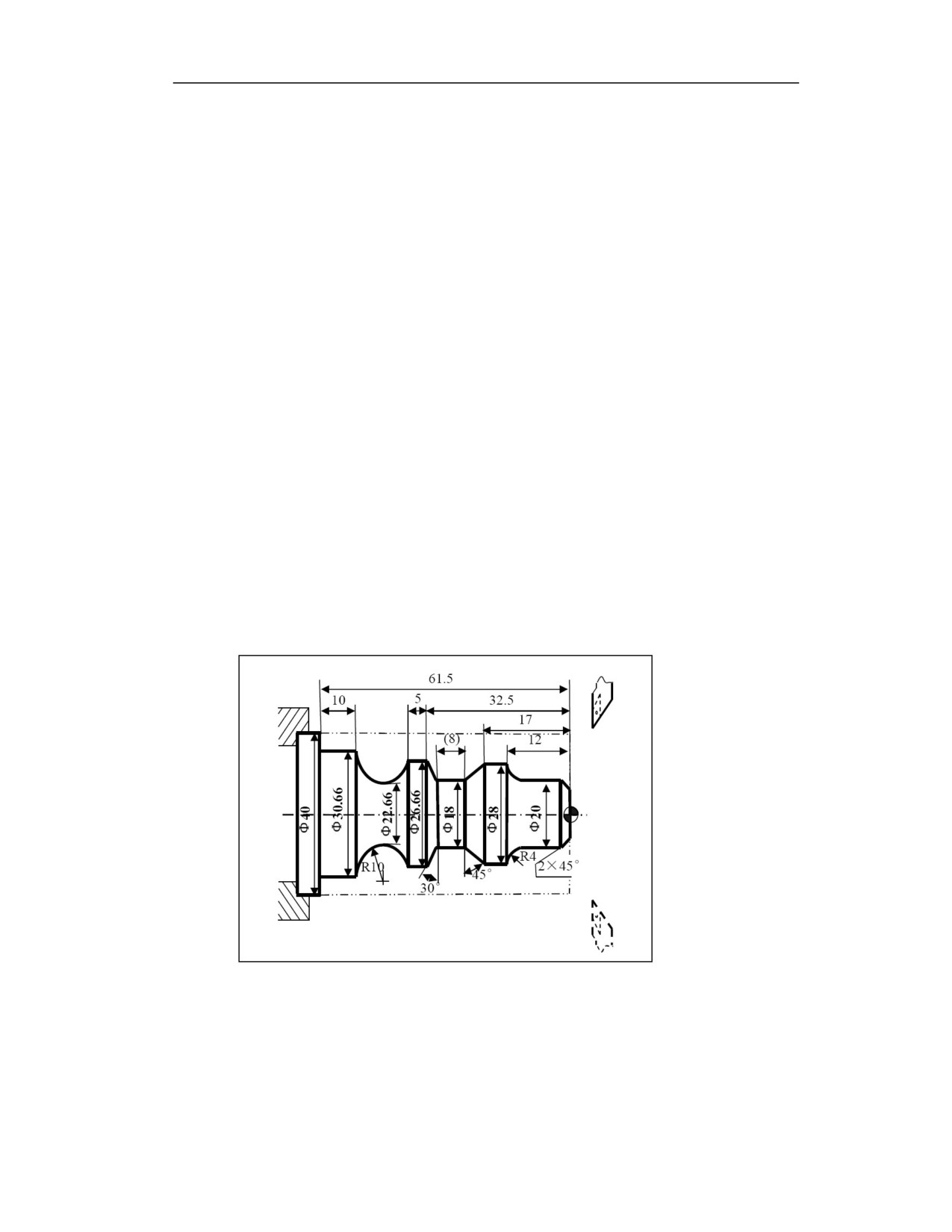
G71U1R1P8Q16X-0.4Z0.1 F100; Machining in inner diameter roughing cycle
N5 G00 X80 Z80; After rough cutting, move to tool change position
N6 T0202; Change to No.2 tool, and determine the coordinate system
N7 G00 G41X6 Z5; Tool nose radius compensation is added to No. 2 tool
N8 G00 X44; Finishing contour starts, move to Φ44 outer circle
N9 G01 Z-20 F80; Finishing Φ44 outer circle
N10 U-10 W-10; Finishing outer cone
N11 W-10; Finishing Φ34 outer circle
N12 G03 U-14 W-7 R7; Finishing R7 arc
N13 G01 W-10; Finishing Φ20 outer circle
N14 G02 U-10 W-5 R5; Finishing R5 arc
N15 G01 Z-80; Finishing Φ10 outer circle
N16 U-4 W-2; Finishing chamfer 2×45°, finishing contour end
N17 G40 X4; Exit machined surface, cancel tool radius compensation
N18 G00 Z80; Exit inner hole of workpiece
N19 X80; Return to starting point of program or tool change position
N20 M30; Spindle stop, main program end and reset
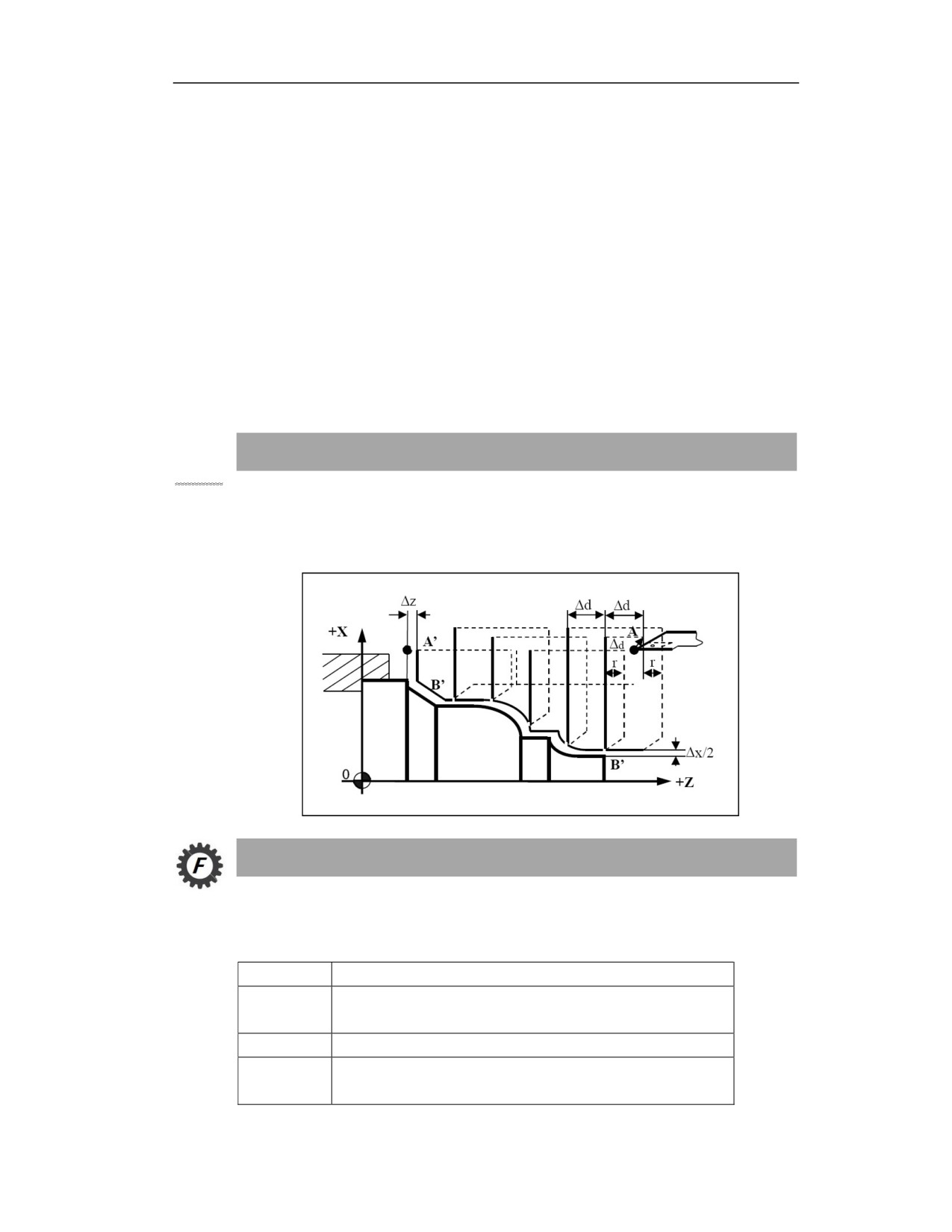
Example 3: Use the outer diameter roughing multiple repetitive cycle with pocket to compile the
processing program of the part shown in the figure below, where the dashed line is the workpiece
blank.
%3327
N1 T0101; Change to No.1 tool, and determine the coordinate system
N2 G00 X80 Z100 ; Move to starting point of program or tool change position
M03 S400; Spindle rotates CW at 400r/min
N3 G00 X42 Z3; Move to the starting point of cycle
311
N4G71U1R1P8Q19E0.3F100 ; Machining in roughing cycle with pocket
N5 G00 X80 Z100 ; Move to tool change position after roughing
N6 T0202; Change to No. 2 tool, and determind the coordinate system
N7 G00 G42 X42 Z3; Tool radius compensation is added to No. 2 tool
N8 G00 X10; Finishing contour starts, move to extension line of chamfer
N9 G01 X20 Z-2 F80; Finishing chamfer 2×45°
N10 Z-8 ; Finishing Φ20 outer circle
N11 G02 X28 Z-12 R4; Finishing R4 arc
N12 G01 Z-17; Finishing Φ28 outer circle
N13 U-10 W-5; Finishing tangent cone
N14 W-8 ; Finishing Φ18 outer circle
N15 U8.66 W-2.5; Finishing tangent cone
N16 Z-37.5 ; Finishing Φ26.66 outer circle
N17 G02 X30.66 W-14 R10 ; Finishing R10 tangent arc
N18 G01 W-10; Finishing Φ30.66 outer circle
N19 X40 ; Exit machined surface, finishing contour end
N20 G00 G40 X80 Z100; Cancel tool radius compensation, return to tool change
position
N21 M30; Spindle stop, main program end and reset
Note
(1) The G71 comand must have P, Q addresses ns, nf which must correspond to the start and end
sequence numbers of the finishing path, otherwise the cycle processing cannot be performed;
(2) The block of ns must be G00/G01 command, that is, the movement from A to A'must be a
linear or point positioning movement;
(3) In the blocks from sequence number ns to sequence number nf, subprogram should not be
included;
(4) The block of G71ns must be monotonically increasing or decreasing when there is not groove.
(5) The rough turning cycle is realized by the G71 command with addresses P and Q. The F S and
T functions specified in the motion command are invalid. But the F S and T functions specified
in the G71 block or the previous block are valid.
(6) When the constant speed limit is used for cutting speed control, the G96 or G97 specified in
the motion command between "ns" and "nf" is invalid. It is valid to specify G96 or G97 in the
G71 block or the previous block.
(7) If user needs to process contours with non-monotonic increasing or decreasing in Z direction,
the processing path between "H1", "ns" and "nf" in the G71 command line. If both X axis and Z
axis are monotonous increasing or decreasing, the machining allowance at this time is represented
312
by "XZ"; if there is a groove on the processed contour path in the X direction, the machining
allowance at this time is represented by "E".
(8) In principle when machining the outer circle, the cycle starting point must be established
higher than the highest point of the contour; when machining the inner hole, it must be lower than
the lowest point of the contour. (The starting point of the cycle can be controlled to be 0 to 1mm
lower than or higher than the highest point of the contour through the machine user parameter
010161)
(9) 10 pockets are supported at maximum for the machining of contour with pocket.
(10) G71 cannot be in the same line as M code
(11) In the any line with scanning mode, the block between ns and nf cannot be specified.
17.2
End Face Roughing Multiple Repetitive Cycle (G72)
Function and Purpose
This cycle is similar as G71.
The G72 turning is shown in the figure below, where the finishing path is A→A'→B'→B
Command Format
G72W(△d) R(r) P(ns) Q(nf) X(△x) Z(△z) F(f) S(s) T(t);
Parameter
Meaning
W
Cutting depth, without sign. The direction is determined by vector
AA′
R
Retraction amount
P
Sequence number of the first program block (AA' in the below
figure) for finishing path
313
Q
Sequence number of the last program block (BB' in the below
figure) for finishing path
X
Finishing allowance in X direction
Z
Finishing allowance in Z direction
F ST
F, S, T in G72 are valid in roughing, and F, S, T between blocks ns
and nf are valid in finishing
Description
In the G72 cutting cycle, the cutting feed direction is parallel to the X axis, so it is suitable for
face cutting along the X axis.
This cycle is a rough machining cycle. It is necessary to reserve an appropriate allowance for
subsequent finishing. The finishing allowance in the X\Z axis direction is X(x) and Z(z), x
is the allowance on X, z is the allowance on Z.
Since the direction of the allowance is determined by the programmer based on the processing
technology, the system determines the direction of the feed according to the direction of the
finishing allowance set by the program. Therefore, the direction of the finishing allowance
(positive and negative settings) must be correct, otherwise it will cause an error in the feed
direction of the tool.
The relationship between the sign of the finishing allowance and the feed direction is shown in
the figure below. (+) means that the contour allowance is kept in the positive direction of the axis,
and (-) means that the contour allowance is kept in the negative direction of the axis.
Machine tool with rear tool post
Machine tool with front tool post
314
华中 8 型数控系统编程说明书
Example
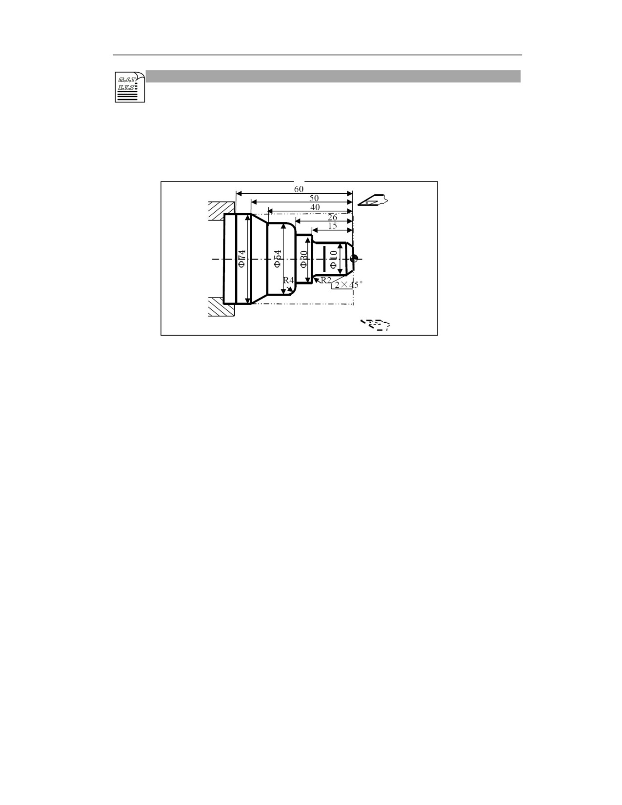
Example 1: Compile the machining program of the part as shown in the figure below: The starting
point of the cycle is required to be A (80, 1), and the cutting depth is 1.2mm. The retraction amount
is 1mm, the finishing allowance in the X direction is 0.2mm, and the finishing allowance in the Z
direction is 0.5mm. The dotted line is the workpiece blank.
%3328
N1 T0101; Change to No. 1 tool, and determine the coordinate system
N2 G00 X80 Z80; Move to starting position of program
N3 M03 S400; Spindle rotates CW at 400r/min
N4 X80 Z1; Move to starting point of cycle
N5 G72W1.2R1P8Q17X0.2Z0.5F100 ; Machining in face roughing cycle
N6 G00 X100 Z80; Move to tool change position after roughing
N7 G42 X80 Z1; Tool nose radius compensation is added
N8 G00 Z-53; The finishing contour starts, and move to extension line of chamfer
N9 G01 X54 Z-40 F80; Cone finishing
N10 Z-30; Φ54 outer circle finishing
N11 G02 U-8 W4 R4; R4 arc finishing
N12 G01 X30; Z26 face finishing
N13 Z-15; Φ30 outer circle finishing
N14 U-16; Z15 face finishing
N15 G03 U-4 W2 R2; R2 arc finishing
N16 G01 Z-2; Φ10 outer circle finishing
N17 U-6 W3;
2×45°chamfer finishing, contour finishing end
N18 G00 X50; Exit machined surface
N19 G40 X100 Z80; Cancel radius compensation, return to starting position of
program
N20 M30; Spindle stop, main program end and reset
315
华中 8 型数控系统编程说明书
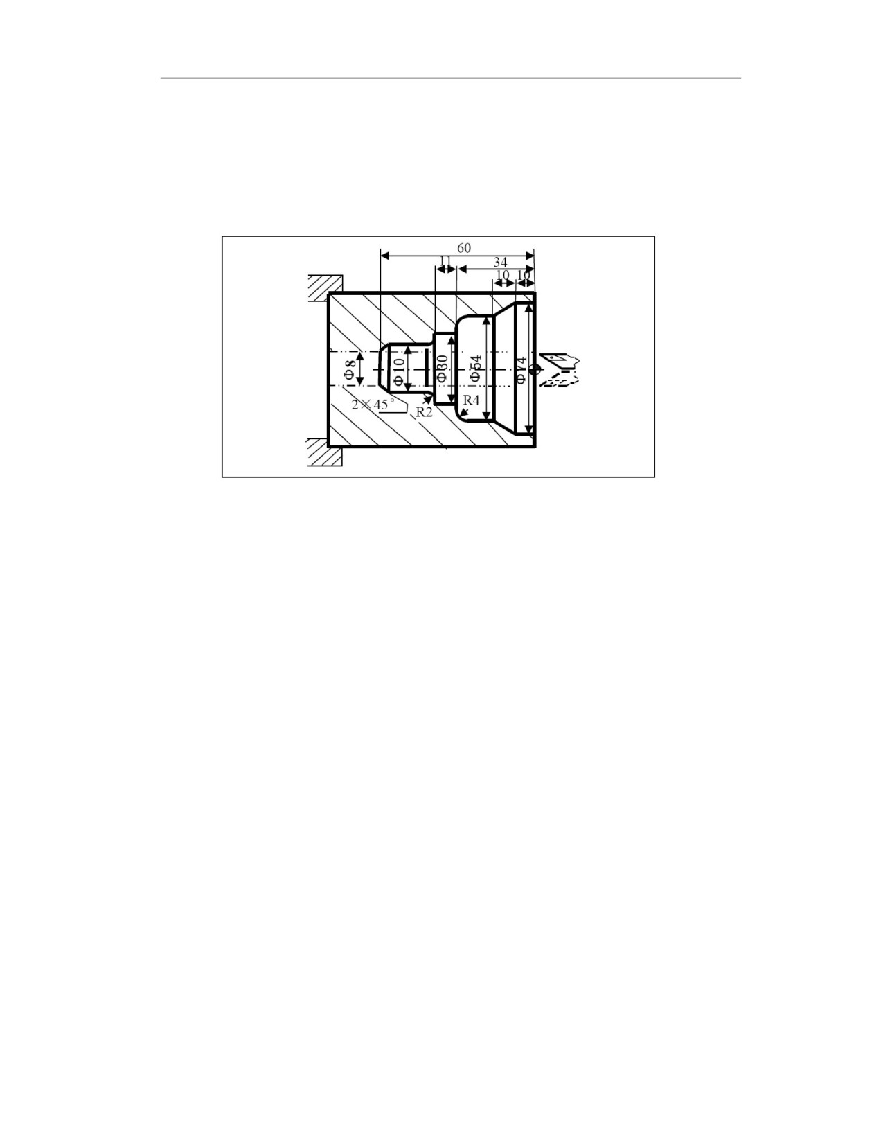
Example 2: Compile the machining program of the part as shown in the figure below: The starting
point of the cycle is required to be A (6, 3) and the cutting depth is 1.2mm. The retraction amount
is 1mm, the finishing allowance in the X direction is 0.2mm, and the finishing allowance in the Z
direction is 0.5mm. The dotted line is the workpiece blank
%3329
N1 T0101; Set coordinate system
N2 G00 X100 Z80; Move to starting point
N3 M03 S400; Spindle rotates CW at 400r/min
N4 G00 X6 Z3; Move to starting point of cycle
N5 G72W1.2R1P6Q16X-0.2Z0.5F100; Machining in face roughing cycle
N6 G00 Z-61; Contour finishing starts, move to extension line of chamfer
N7 G01 U6 W3 F80;
2×45°chamfer finishing
N8 W10; Φ10 outer circle finishing
N9 G03 U4 W2 R2; R2 arc finishing
N10 G01 X30 ; Z45 face finishing
N11 Z-34; Φ30 outer circle finishing
N12 X46 ; Z34 face finishing
N13 G02 U8 W4 R4; R4 arc finishing
N14 G01 Z-20; Φ54 outer circle finishing
N15 U20 W10; Cone finishing
N16 Z3; Φ74 outer circle finishing, contour finishing end
N17 G00 X100 Z80; Return to tool setting position
N18 M30; Spindle stop, main program end and reset
316
华中 8 型数控系统编程说明书
Note
(1) The rough turning cycle is realized by the G72 command with addresses P and Q. The F, S
and T functions specified in the motion command are invalid. But the F, S and T functions
specified in the G72 block or the previous block are valid.
(2) When the constant speed limit is used for cutting speed control, the G96 or G97 specified in
the movement command between "ns" and "nf" is invalid. It is valid to specify G96 or G97 in the
G72 block or the previous block.
(3) The block between sequence numbers "ns" and "nf" cannot call subprograms.
(4) The block trajectory between "ns" and "nf" must be gradually increased or decreased in X
direction. Non-monotonously increasing or decreasing contour shape processing is not currently
supported.
(5) In principle, the cycle starting point on Z-axis must be higher than the highest Z point of the
contour; (the cycles tarting point on Z can be controlled to be 0 to 1mm lower than the highest
point of the contour through the Machine User Parameters 010161).
(6) G72 command cannot be the same line as the M code.
(7) In the any line with scanning mode, the blocks between ns and nf cannot be specified
17.3
Closed Turning Multiple Repetitive Cycle (G73)
317

Function and Purpose
This cycle function is suitable for the machining of blanks with rough outlines, such as forging
and casting parts. When processing this kind of blank parts, this function can effectively achieve
a relatively balanced margin.
Command Format
G73 U(I) W(K) R(r) P(ns) Q(nf) X(△x) Z(△z) F(f) S(s) T(t);
Parameter
Meaning
W
Cutting depth, without sign. The direction is determined by vector
AA′
R
Retraction amount
P
Sequence number of the first program block (AA' in the below
figure) for finishing path
Q
Sequence number of the last program block (BB' in the below
figure) for finishing path
X
Finishing allowance in X direction
Z
Finishing allowance in Z direction
F ST
F, S, T in G72 are valid in roughing, and F, S, T between block ns
and nf are valid in finishing
Description
When this function is cutting the workpiece, the tool path is shown in the figure below. The tool
gradually feeds to make the path gradually close to the final shape of the part, and finally cut into
the shape of the workpiece. The finishing path is A→A'→ B'→B.
318
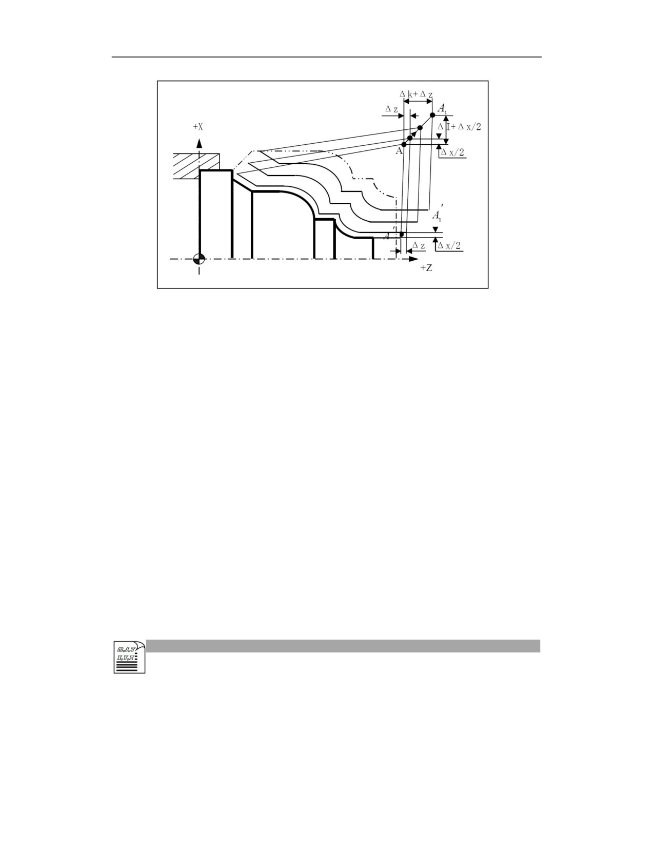
I: Roughing allowance in X axis direction
k: Roughing allowance in Z axis direction
r: Number of rough cuts
ns: Sequence number of the first program block (AA' in the below figure) for finishing path
nf: Sequence number of the last program block (BB' in the below figure) for finishing path
Δx: Finishing allowance in X axis direction
Δz: Finishing allowance in Z axis direction
f,s,t:F, S, T in G73 are valid in roughing, and F, S, T between block ns and nf are valid in
finishing
Note
ΔI and ΔK represent the total cutting amount during roughing, the number of roughing is r, the
cutting amount in X and Z direction is ΔI/r and ΔK/r;
The cycle machining is realized based on the P and Q values in G73 block. Note the signs of △
x and △z, △I and △K.
Example
Example 1: Set the starting point of cutting at A (60, 5); the rough machining allowances in the X
and Z directions are 3mm and 0.9mm respectively; the number of rough machining is 3; the
finishing allowances in the X and Z directions are 0.6mm and 0.1mm respectively. The dotted
line part is the workpiece blank.
319