HNC8 Series CNC Controller. Programming Manual (V2.4) - page 10
Canned cycle
There are two types of canned cycles. One is a general canned cycle, which is mainly used in
turning, milling, drilling, etc., and the other is a user canned cycle, which is created based on the
special needs of users.
Refer to Chapter 12 for the specific use of the general canned cycle.
User can add subprograms to the file of user canned cycle (USERDEF.CYC) as needed, and use
the corresponding G command in the main program. (The correspondence between G command
and user canned cycle subprogram number is shown in Chapter 14 and Chapter 15)
Open the user-defined cycle file USERDEF.CYC, index to the following contents, and add them
in turn. For example, add user subprogram 1010.
%1010
G01X10Y10F1000
Z50
M99
The main program uses command G1010 to call the above program.
19.2.6 Macro Program Example
Application example
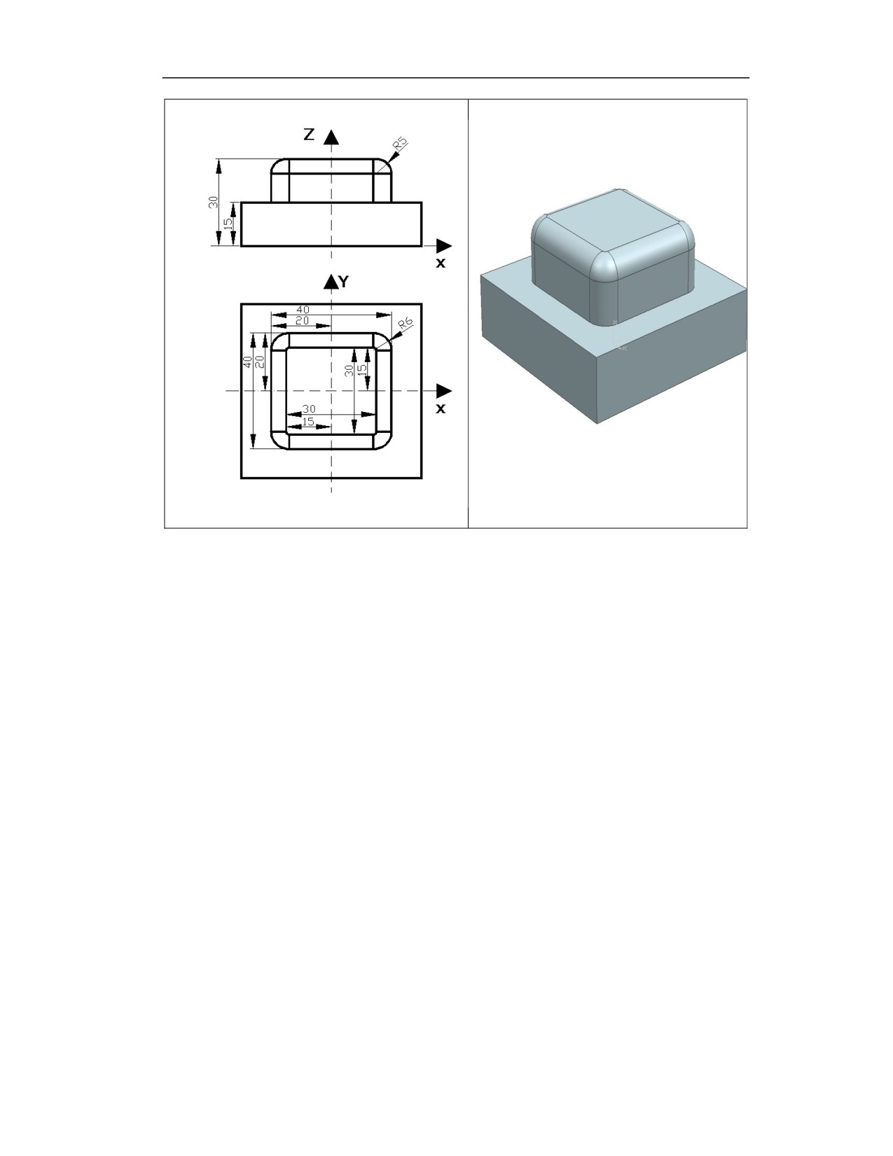
As shown in the figure, use a ball-end milling cutter to process the R5 fillet surface.
360
%0001
(The tool position point is the ball center)
G92 X-30 Y-30 Z25
#0=5
(Fillet radius)
#1=4
(Radius of ball-end cutter)
#2=180
(The initial value of the step angle γ. Unit: Degree)
WHILE #2 GT 90
G01 Z[25+[#0+#1]*SIN[#2*PI/180]]
(Calculate Z axis height)
#3=ABS[[#0+#1]*COS[#2*PI/180]]-#0 (Calculate radius offset)
G10 L12 P3 R[#3]
G01 G41 X-20 D3
Y14
G02 X-14 Y20 R6
G01 X14
G02 X20 Y14 R6
G01 Y-14
G02 X14 Y-20 R6
G01 X-14
G02 X-20 Y-14 R6
G01Y30
G01 X-30
G40 Y-30
#2=#2-10
ENDW
M30
361
19.3
Manual Calling Subprogram
Function and Purpose
In JOG mode, user can customize the buttons on the MCP panel, set the G register to 1 by the
button, and call the related suprograms, thereby realizing some more complex functions, such as
tool change, spindle C/S switching, etc.
The correspondence of G register points to subprograms is shown in the following table
G register point
Canned cycle subprogram
G2637.1
Call canned cycle subprogram O1007
G2637.2
Call canned cycle subprogram O1008
G2637.3
Call canned cycle subprogram O1009
G2637.4
Call canned cycle subprogram O1010
G2637.5
Call canned cycle subprogram O1011
G2637.6
Call canned cycle subprogram O1012
G2637.7
Call canned cycle subprogram O1013
G2637.8
Call canned cycle subprogram O1014
G2637.9
Call canned cycle subprogram O1015
G2637.10
Call canned cycle subprogram O1016
G2637.11
Call canned cycle subprogram O1017
G2637.12
Call canned cycle subprogram O1018
G2637.13
Call canned cycle subprogram O1019
G2637.14
Call canned cycle subprogram O1020
G2637.15
Call canned cycle subprogram O1021
F2637.0
Status bit: subprogram is running in JOG mode
Description
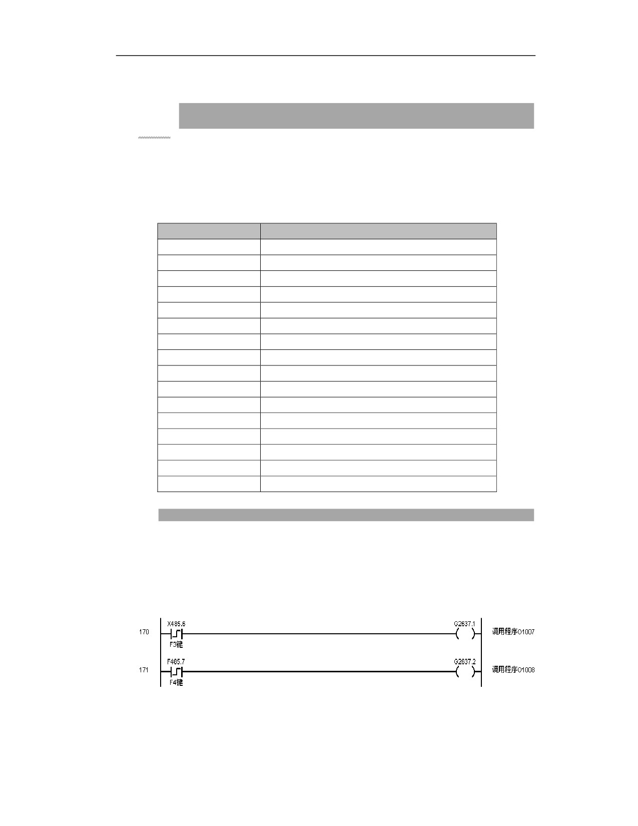
(1) In PLC, the program can be created as shown below (user can customize the buttons based on
the actual situation), the G command signal can be output, and the corresponding subprogram can
be called.
(2) In JOG mode, call the corresponding subprogram by clicking the button. Click the F3 button
as shown in the figure above to call
O1007 subprogram.
362
Note
(1) During the execution of the program, F2637.0 is always 1, and the buttons on the panel are in
the shielding state except for the reset and emergency stop buttons, and the clicks are invalid;
when the corresponding G register signal (e.g. G2637.1) is 0, F2637.0 is 0 after the subprogram
is executed.
(2) Currently, subprograms O1007 to O1021 must be placed in the file USERDEF.CYC. The
subprogram corresponding to the O1007 program starts with %1007, and O1008 corresponds
to %1008, and so on. In the line before M99 at the end of each subprogram, G80 must be added
to clear the canned cycle mode.
(3) When the subprogram is called manually, the buttons on the MCP panel should be in the
shielding state except for emergency stop button, but for the PLC output control buttons (such as
spindle CW, spindle CCW, cooling, etc.), PLC needs to be changed to shield these buttons.
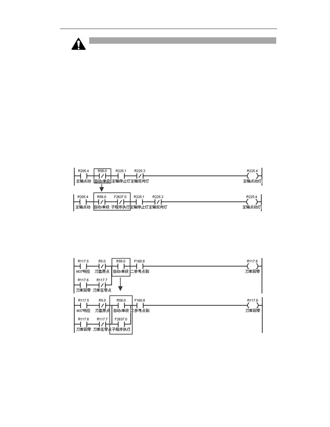
For example, shielding the function key of spindle CW:
For the M command that is only executed in the auto/single-block mode, the normally open point
of F2637.0 should be connected in parallel in the program, as shown in the figure below, to ensure
that the M command can be executed normally during calling subprogram in JOG mode.
363

20 High-speed High-Precision Function
20.1
Machining Optimization Function G125/G126
Function and Purpose
If the processing optimization function is turned on by the G command (G125) in the program,
the CNC system can optimize the speed of the related processing program (G code program) to
improve the surface quality of the part. This function is mostly used for finishing of curved or
mold parts.
Command Format
G125 ; Call machining optimization function
G126 ; Cancel machining optimization function
Example
The processing optimization function used to optimize standard curved surface parts processing
procedures
%0001
G40 G17 G49 G80 G90
G54
N0010 (ROUGH_MILL)
G0 X46.694 Y-51.205 S6000 M03
G125
; Call machining optimization function
Z5.
Z2.521
……………………………
G2 X-40.694 Y-53.651 I13.015 J58.936
G1 X-46.694 Y-51.382
G1 Z2.521
G0 Z5.
X46.694 Y-44.44
Z2.521
G1 Z-0.479
G1 X40.694 Y-47.014
G2 X16.255 Y-51.349 I-21.491 J50.099
G1 X-17.851 Y-51.371
………………………………
364
G126
; Cancel machining optimization function
M30
Description
Interface button and logo introduction
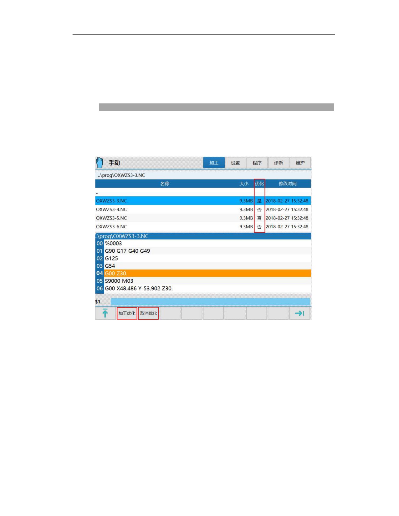
The following figure shows the program selection interface
Machining optimization
Optimize the processing program (G code) and generate the corresponding optimization file.
Operation
Select the corresponding program and click the key, then the program will be optimized. The
interface prompt bar and pop-up box display the processing optimization progress, as shown
below:
365
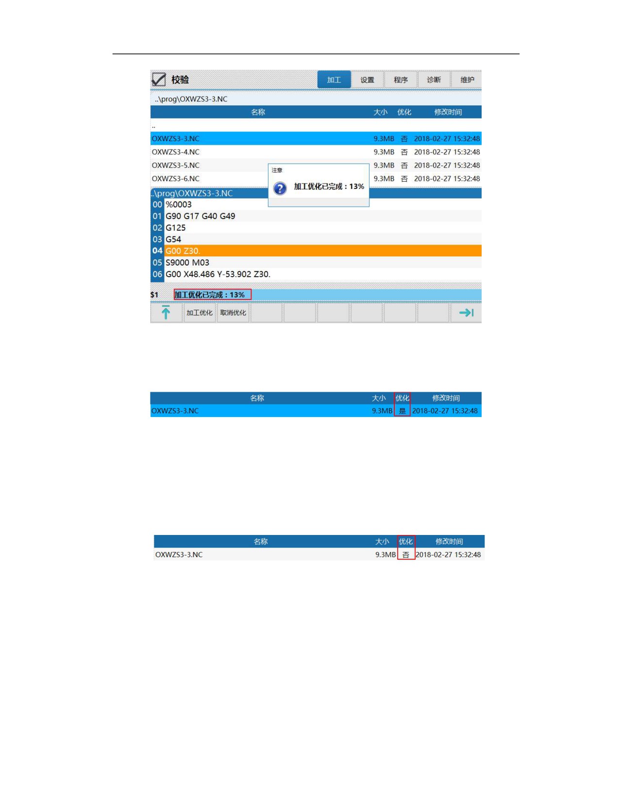
After the program is optimized, the optimization column will display "Yes", as shown in the figure
below.
Cancel optimization
When the program optimization process is terminated, the optimization column displays "No".
Operation
Select the corresponding program and click the button, then the program optimization will be
cancelled, and the optimization column will display "No", as shown in the figure below:
Optimization column
"Yes" means that the processing optimization operation has been completed for G code program,
"No" means that the processing optimization operation has been not completed for G code
program.
Description of processing program optimization
G code optimization operation
All G codes can be optimized through the processing optimization key. The interface operation
366

and corresponding handling are shown in the following table.
Object
Operation
Result
The G code is optimized normally. After the
Unoptimized G code
optimization is completed, the optimization column
displays "Yes".
G code optimization is canceled, and the optimization
Optimized G code
clolum displays “No”
Note
Different programs have different processing optimization procedures. Generally, t
he larger the program, the longer the optimization time, even as long as several
minutes. The program interface will display "Processing optimization complete
d..%, please wait patiently”.
In the process of processing optimization, the processing optimization interface is
locked and cannot be switched to other interfaces until the optimization is compl
eted, and then other operations can be performed.
For ordinary programs (<20M), during the optimization process, the optimization
completion progress is displayed in percentage (%) on the prompt bar; for super
large programs (>20M), during the optimization process, the optimization progress
is displayed as the number of program lines that has been optimized .
If there is an alarm in the system or an alarm occurs during the optimization, th
e optimization will fail, and user needs to perform the reset and cancel the opti
mization. The following prompt will be given: the system alarm causes the proce
ssing optimization to fail, press reset button to cancel the optimization.
Optimized G-code editing and corresponding optimization
When editing or modifying the optimized G code, the program needs to be re-optimized
automatically. The specific operation and handling are shown in the following table:
Operation
Handling
Replace the optimized program
Optimization of G code is canceled, and optimization column
with the program of the same
displays “No”
name
Optimization of G code is canceled, and optimization column
Delete optimized program
displays“No”
Save as or copy an optimized
The program is still being optimized, the optimization column
program
indicates “Yes”
367

The program saved or copied is not optimized, the optimization
column indicates "No"
The renamed program is still being optimized, the optimization
Rename the optimized program
column indicates “Yes”
Modify the optimized program,
Optimization of G code is canceled, and optimization column
and save the modification
indicates “No”
Click “cancel optimization”
Optimization of G code is canceled, and optimization column
button for the optimized program
indicates “No”
Optimization of called subprograms in the main program
In the main program/subprogram calling mode, the optimization processing mode can be called
by adding G125 to the main program, so that all subprograms adopt the optimization processing
mode. It is also possible to optimize a subprogram separately to realize the optimization
processing of the subprogram.
Operation
Handling
All subprograms called by the main program can be optimized
Optimize main program
synchronously, and the optimization attribute of each program is
displayed as "Yes".
Optimize subprogram
The optimization attribute of the corresponding subprogram is
seperately
displayed as "Yes".
Modify the optimized
Optimization of main program is canceled, and optimization
main program
column indicates “No”
Modify the optimized
Optimization of G code is canceled, and optimization column
subprogram
indicates “No”
Note
When the main program is used in combination with an external subprogram, if a
certain subprogram needs to use the optimization processing mode, add the G125
command at the head of the subprogram, add the G126 command before M99 at the
end of the program, and optimize the corresponding subprogram.
Currently calling processing optimization function of internal subprogram is not
supported.
The processing optimization function of M98P_L_ mode is not supported.
Activation of machining optimization mode
The optimized program can call the mold optimization processing mode only through the G
command calling. Generally, the G125 command is added to the program header.
368
Related G commands
G125: Indicates that the optimization processing function is turned on.
G126: Indicates that the optimization processing function is turned off.
Note
For unoptimized G code, G125 is added to the program header.When the program is
running, an alarm will be issued and prompts user "specified processing optimization
code does not exist".
If no G125 command is added to the optimized G code program, it will run in the
original mode and the original speed planning algorithm is selected to run the
program.
If the G125 command is added to the optimized G code program, it will run in the
optimized mode, and the new speed planning algorithm will be selected to run the
program.
Parameter configuration
1) Internal parameters of the algorithm
The following parameters are used internally by the algorithm, and can be set according to the
following instructions under normal circumstances; if the modification is needed, they must be
modified under the guidance of the developer.
040045 Standard field radius 1.35
Note: This parameter is to set the neighborhood radius length based on neighborhood speed
planning, the default value is 1.35.
040046 Single point deceleration angle scale factor 1.000
Along the tool path, when the tangent vector angle between two adjacent blocks is greater than a
certain threshold (the default is 10°), the end of the block is used as the deceleration point at the
end. This parameter is used to adjust the angular velocity threshold.
Actual threshold=10*single point deceleration angle scale factor
040047 Minimum angle ratio in the angle ratio criterion 3.000
This parameter is used to set the determination threshold of the angle ratio of front and back
ends of the block in the end point angle ratio criterion.
369
040048 Minimum angle ratio in the relatively long line segment criterion 0
This parameter is used to set the determination threshold of the angle ratio of the front and back
ends of the block in the relatively long line segment criterion.
040049 Criterion combination mode 0X0
This parameter is used to set the criteria combination method and the curvature calculation
optimization method.
Bit 0
0: corner criterion, relatively long line segment criterion, and inflection point criterion are all
effective.
1: Relatively long line segment criterion and inflection point criterion are effective
2: Relatively long line section criterion and corner criterion are effective
Bit 1
0: Curvature radius calculation mode 1, the default mode.
1: Curvature radius calculation mode 2.
040068 The second processing code spline merging enable 0
This parameter is used to enable the spline merging function of the second processing code.
0: Turn off the spline merging of the second processing code
1: Turn on the spline merging of the second processing code
040069 Speed planning mode 0
There is a motion planning mode for small line segment interpolation in the HNC-8 CNC system.
Currently 0 is set.
(1) Recommended parameter of small line segment
Basic small line segment parameters (040069-040087) can be based on this, as shown in the
following table
Maximum length of
Minimum
Contour
Read-ahead
Command
small line segment
smooth interior
allowance (mm)
blocks
smoothing
(mm)
angle
period
(°)
370
1.5
0
0.015
800
20
Acceleration time
Acceleration
Centripetal
Smooth closing
Collinear
proportional factor
jerk time
acceleration
of preprocessing
angle
proportional
(mm/s2)
threshold
factor
(radians)
1
1
200~2000
1
0.017
G05.1Q1, G05.1Q2, and G05.1Q3 can be set.
(2) Axis parameter
Acceleration deceleration time constant (ms)
Acceleration deceleration jerk time constant (ms)
16
8
Example
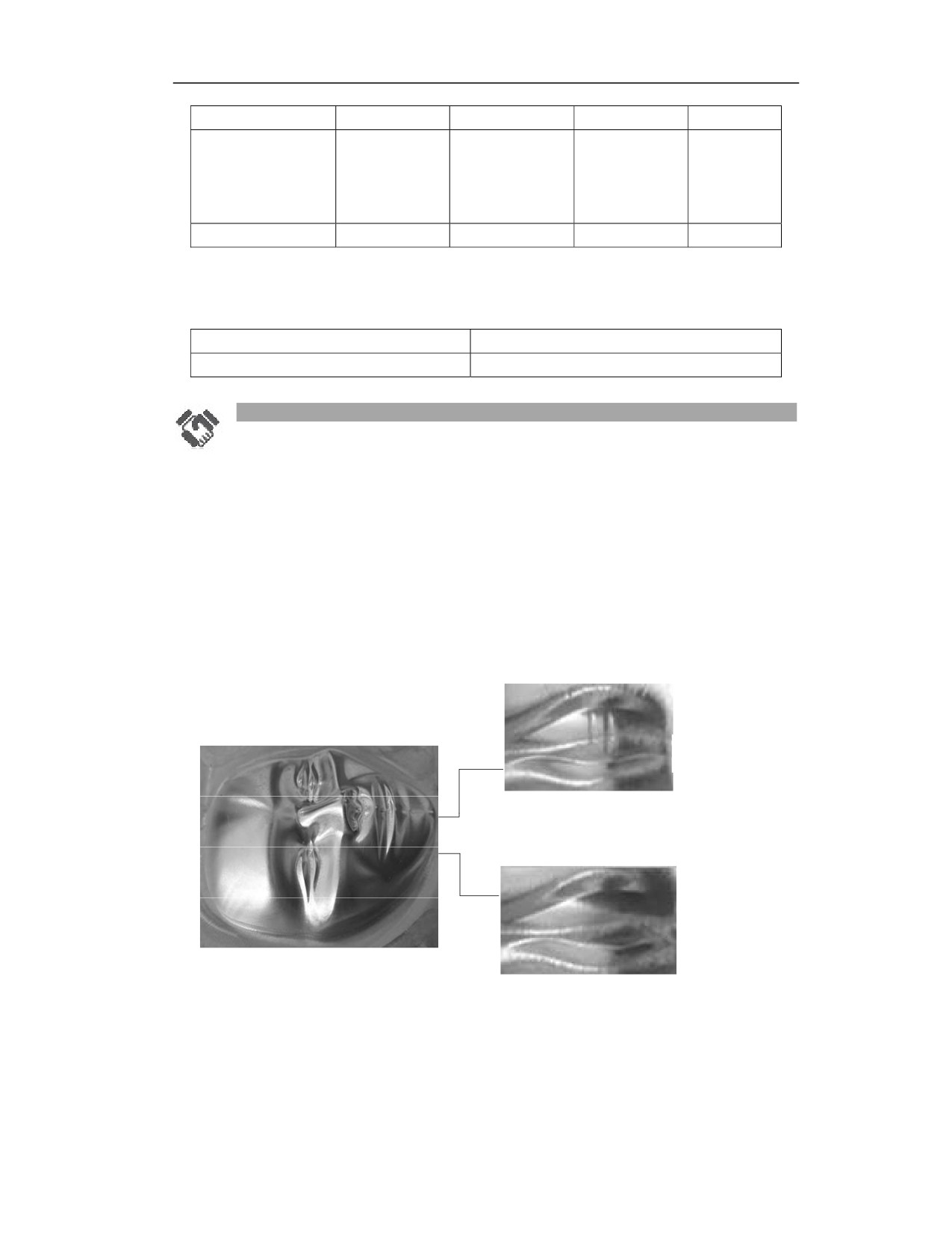
Using of mold optimization processing mode
The mold optimization processing mode improves the processing speed planning, reduces the
frequency of the speed fluctuations during the processing, improves the smoothness of the
processing speed, and at the same time ensures the consistency of the speed of the adjacent tool
path in the three-dimensional surface processing, improves the processed surface quality, and
effectively solves the obvious cut marks in surface processing. In the case of the same processing
effect, the processing efficiency can be improved.
High-speed machining
Without machining
optimization
After machining
optimization
371
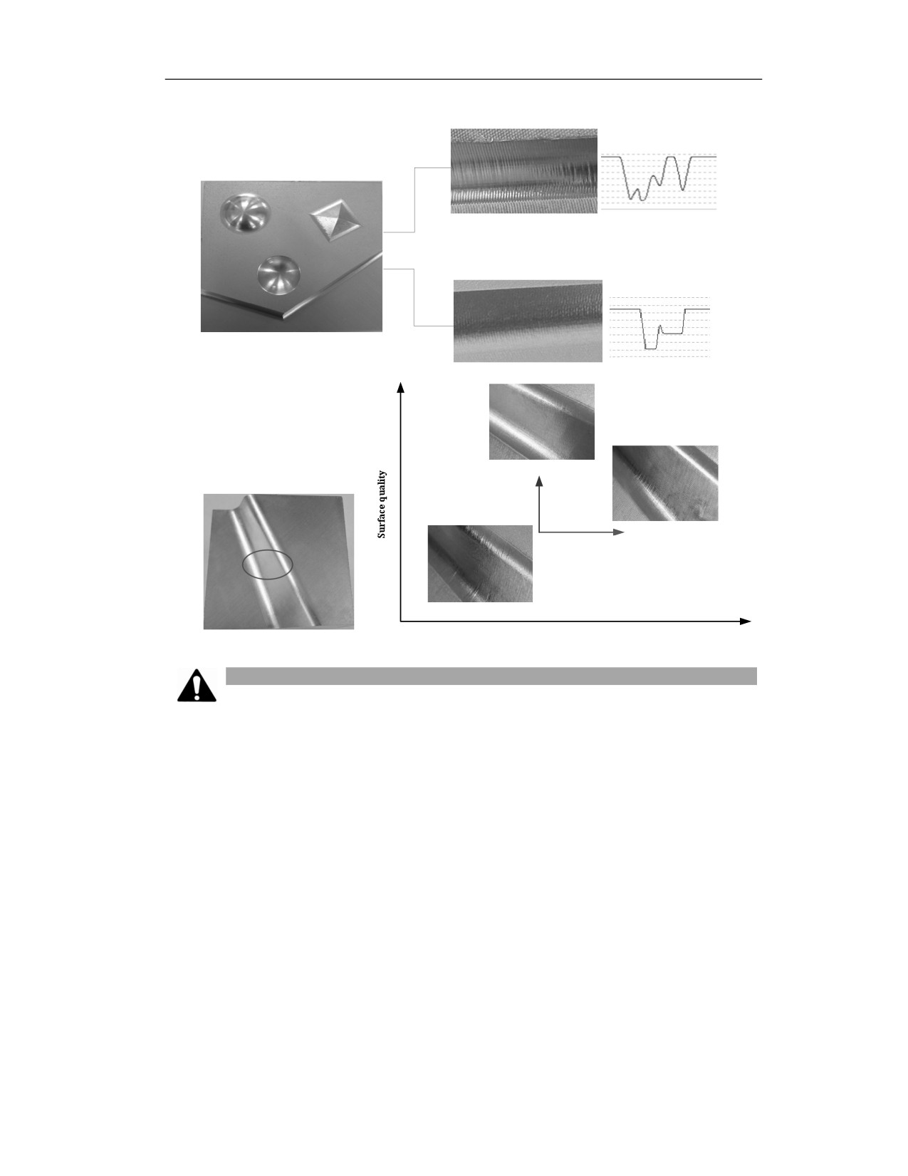
Without machining
optimization
Resultant speed curve
High-speed machining
After machining
optimization
Resultant speed curve
Improvement of machining
efficiency and quality
High
Comparing with ordinary
machining, the optimization
machining control can increase
the surface quality when the
machining efficiency is
constant.
7min33s
Optimization
machining
control
9min6s
Ordinary
machining control
Low
7min16s
Short
Machining time
Long
Note
(1) Use G125 in the program to turn on the optimization processing mode. If G125 is not used to
turn on the optimization processing mode, the processing is the same as the normal version.
(2) The optimization processing mode is generally used for three-dimensional surface finishing,
mainly to solve the obvious over-cutting in the processing of complex parts, and at the same time,
it can improve the processing efficiency while ensuring the processing quality.
(3) The G125 command must be placed before the traverse command of the program head.
(4) When the main program is used in combination with an external subprogram, if a certain
subprogram needs to use the optimization processing mode, then add G125 command at the head
of the subprogram, add G126 command before M99 at the end of the program, and optimize the
corresponding subprogram.
(5) The internal subprogram processing optimization function is not supported.
(6) The processing optimization function in M98P_L_ mode is not supported.
372

20.2
High Speed High Precision Mode Selection(M)(G05.1)
Function and Purpose
In modern CNC systems in order to ensure the quality of the contour processing, in addition to
the good mechanical accuracy of the CNC equipment, a CNC system with high-speed processing
capabilities and high-speed and high-precision functions is also required.
For the actual contour processing, it can generally be divided into roughing, semi-finishing and
finishing according to the parts processing procedure. Regardless of the processing mode, the
actual processing and finished product quality requirements can be decomposed as follows:
Machining
Feature
requirement
Focus on the processing time and increase the processing speed of the free
High efficiency
curve. There is no high requirement on dimensional precision of workpiece.
It is generally required for roughing or intermediate processing.
Balance of efficiency
There is no high requirement for processing time and accuracy, but both
and precision
need to be controlled within a certain range.
Focus on the dimensional accuracy of the workpiece. The surface quality
High precision
is high, and the processing efficiency is not considered. It is generally
finishing.
As shown in the above table, in the actual machining process, both efficiency and accuracy cannot
reach the optimal level, and only one of them can be emphasized or a balance between them is
maintained based on different process characteristics and requirements. There are a series of
control parameters that play a major role in processing efficiency and processing accuracy in the
system. The combined application of these control parameters can meet different processing
requirements.
Through this command, different processing modes can be switched to meet the processing
requirements of different technological characteristics.
Command Format
G05.1 Q_; Specifying processing mode
G05.1 Q0; Default mode
Parameter
Meaning
Q_
Select the processing mode, the value can be 0, 1, 2, 3. The four groups of
processing modes can be switched mutually by G05.1Q_.
373

Command
Description
G05.1Q0
Default mode: focus on a balance of efficiency and precision
G05.1Q1
High precision mode: focus on the machining surface and
dimensional precision
G05.1Q2
High-speed high-precision mode: focus on smoothness of processing
and a balance of efficiency and precision
G05.1Q3
High speed mode: focus on efficiency, improve processing speed of
free curve
With G05.1Q1, G05.1Q2, and G05.1Q3, user selects different high-speed and high-precision
machining modes and configures different parameters (speed smoothing, spline smoothing, etc.)
to achieve high efficiency, high precision, or balance of efficiency and precision.
Example
High-speed high-precision mode is used to edit small line segment program
1) G05.1Q0
; Default mode; balance of efficiency and
precision is focused
example
G54
G0 X48.689 Y-51.225 S6000 M03
G05.1Q0
; Default mode; balance of efficiency and
precision is focused
X46.694 Y-37.445
………………
Z2.521
M30
2) G05.1Q1
; High-precision mode; machining surface and
dimensional precision is focused
Example
G54
G0 X48.689 Y-51.225 S6000 M03
G05.1Q1
; Default mode; balance of efficiency and
precision is focused
X46.694 Y-37.445
………………
Z2.521
M30
3) G05.1Q2
;High-speed high-precision mode; machining smoothness and balance
of efficiency and precision is focused
Example
G54
G0 X48.689 Y-51.225 S6000 M03
374
G05.1Q2
; High-speed high-precision mode; machining smoothness and
balance of efficiency and precision is focused
X46.694 Y-37.445
………………
Z2.521
M30
4) G05.1Q3
; High-speed mode; machining efficiency is focused, and machining
speed of free curve is improved
Example
G54
G0 X48.689 Y-51.225 S6000 M03
G05.1Q3
; High-speed mode; machining efficiency is focused, and machining
speed of free curve is improved
X46.694 Y-37.445
………………
Z2.521
M30
Note
(1) G05.1Q_ can only be called in a single line, and cannot be called in the same line with other
commands.
375

20.3
High Speed High Precision Parameter Setting
Function and Purpose
In the actual CNC machining process, different workpieces processed by the same machine tool
or different parts and procedures of the same workpiece have their own technological
characteristics and processing requirements. The use of a set of control parameters obviously
cannot achieve good processing results. It is necessary to adopt a combination of different control
parameters for different parts and processes for overall coordinated control, so as to achieve the
best processing effect.
Description
Control parameters
Command speed smoothing periods
Parameter type
Parameter
Unit
Value range
Default value
Channel
040082
ms
0 to 50
0
parameter
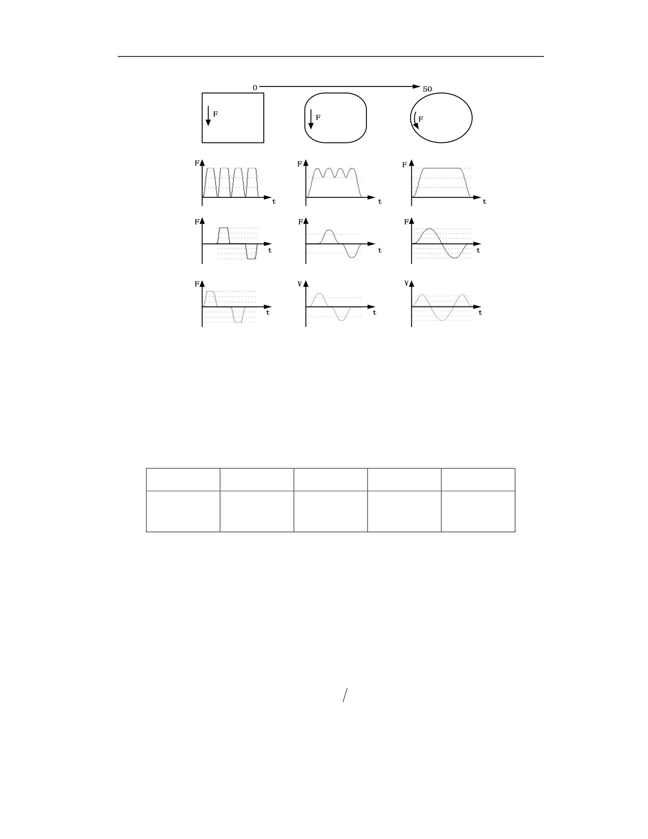
Through the command speed smoothing window, the smooth transition of the command speed is
realized, the speed fluctuation is reduced, the speed stability in the high-speed control is ensured,
the vibration of the machine tool is reduced, and the processing efficiency is improved. The
working principle is shown in the figure below. For a small square (side length <0.5mm), as the
smoothing period increases, the 90° corners of the square will gradually become a circular
transition until it becomes a full circle; The amount of change in the composite speed gradually
decreases until it becomes a constant speed section, and the uniaxial speed gradually becomes a
smooth transition.
376
Command speed smoothing periods
Resultant speed
Resultant speed
Resultant speed
X axis speed
X axis speed
X axis speed
Y axis speed
Y axis speed
Y axis speed
It can be seen from the above principle that the command speed smoothing periods help to
improve the smoothness of processing speed, reduce machine tool vibration and improve
efficiency, and at the same time it will affect machining accuracy. The larger the command
smoothing periods, the lower the accuracy. That is, when the accuracy is the priority, the lower
value the better; when the efficiency is the priority, the larger value the better; when considering
the smoothness (efficiency and accuracy are both balanced), the value is between 10 and 30.
Centripetal acceleration
Parameter type
Parameter
Unit
Value range
Default value
Channel
040084
mm/s2
1.0 to 100000.0
1000.0
parameter
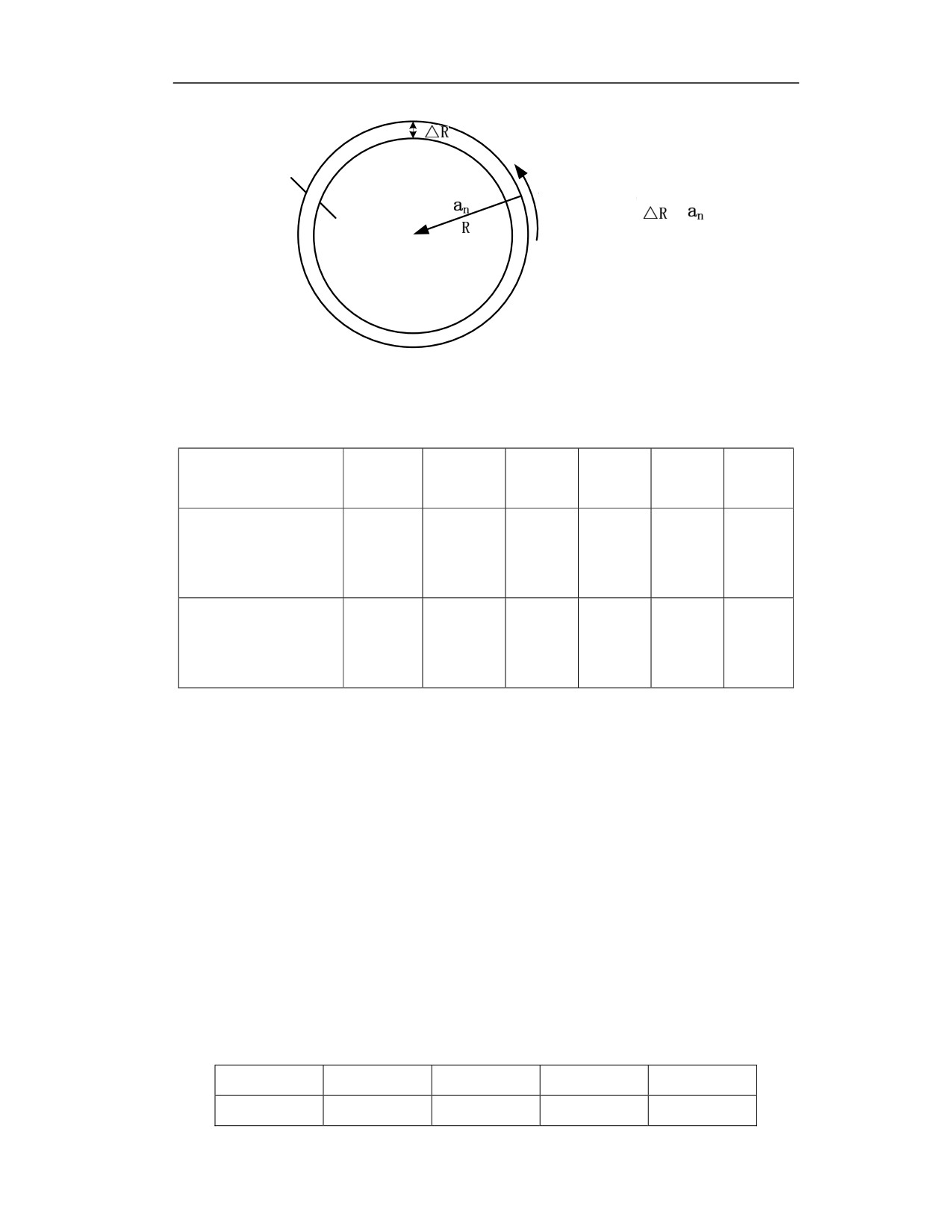
According to Newton's second law, the force will cause the object to produce an acceleration. The
acceleration produced by the centripetal force is the centripetal acceleration. Centripetal
acceleration is a physical quantity that reflects the speed and the direction of circular motion.
Centripetal acceleration only changes the direction of the velocity. The maximum centripetal
acceleration is used to set the limit of the maximum centripetal acceleration.
As shown in the figure below, the centripetal acceleration (na ), linear speed (v ) and radius R
satisfy the following relationship:
2
a
v
R
n
377
Command path
When R is constant,
V (feedrate F)
Actual path
The feed cutting speed of the circular arc can be limited by the centripetal acceleration. The table
of comparison between the maximum feed speed of a circle with a certain radius (R) and the
centripetal acceleration is as follows:
Centripetal acceleration
500
1000
2000
3000
5000
6000
(mm/s2)
R5mm circular
deceleration speed
3000
4242.64
6000
7348.47
9486.83
10392.3
(mm/min)
R1mm circular
deceleration speed
1341.64
1897.36
2683.28
3286.33
4242.64
4647.58
(mm/min)
When the given feedrate F is larger than the circular deceleration speed of the current radius, the
speed will reduce to the circular deceleration speed of the current radius; when the given feedrate
F is lower than the circular deceleration speed of the current radius, the circular feed cutting is
executed at the given speed F.
According to the acceleration principle diagram, for a circular arc with a certain radius (R), the
radius error (△R) is proportional to the centripetal acceleration. Therefore, in the case of accuracy
priority, the feedrate on arc can be limited by reducing the acceleration; in the case of efficiency
priority, the feedrate on arc can be increased by increasing the acceleration, but the centripetal
acceleration needs to be adjusted based on the actual situation to meet the efficiency and precision
requirements.
Example: When the centripetal acceleration is set to 1000 mm/s2 and the given feedrate is
3000mm/min, for an arc with a radius of 5mm, the feed cutting is performed at 3000mm/min; for
an arc with a radius of 1mm, the feed cutting is performed at 1897.36mm/min.
Minimum internal angle of corner smoothing
Parameter type
Parameter
Unit
Value range
Default
Channel
040071
Degree
0 to 180
100
378
parameter
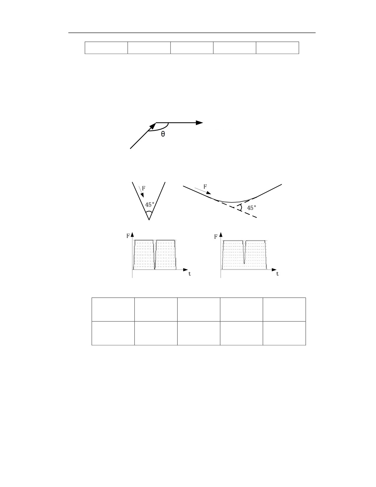
During continuous small line segment interpolation, local speed reduction can be performed based
on the actual programmed path. For situations where the sharpness of contour corner needs to be
highlighted, the speed will be reduced to 0 at the top of the sharp corner. This parameter is used
to set the value of the angle. If the processing angle is smaller than this angle, the exact stop will
be performed. If it is greater than this value, other determinations will be used to plan the speed
reduction at this angle, as shown in the figure below;
If θ is larger than the set value, the
speed will be reduced to 0 at the top of
the sharp corner.
Example: When the minimum interior angle of corner smoothing is set to 90°, the 45° (<90°) and
135° (>90°) corner paths and speed curves are shown in the following figure:
Resultant speed
Resultant speed
Corner deceleration proportional factor
Parameter
Parameter
Unit
Value range
Default value
type
Channel
040074
%
0 to 150
100
parameter
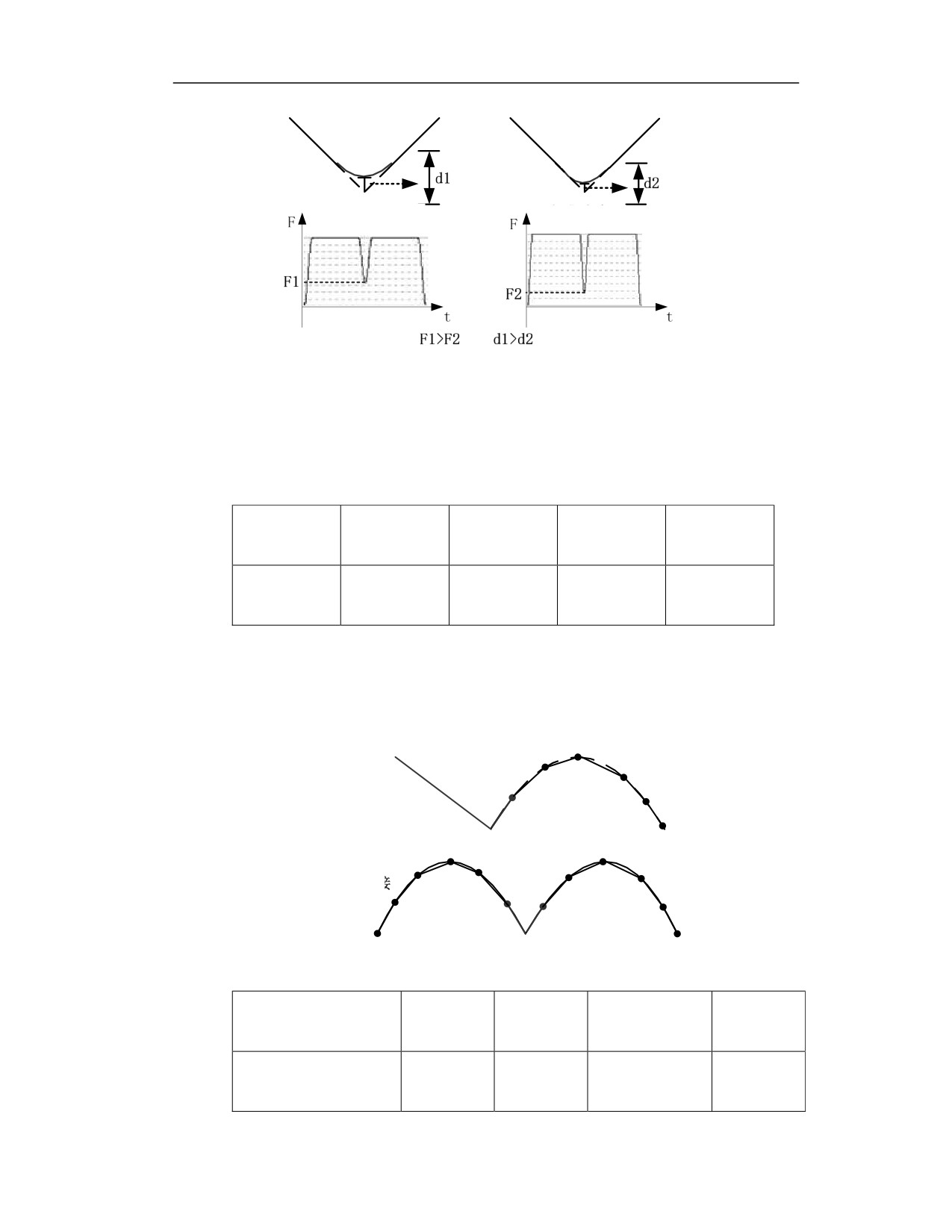
For the polyline of which corner angle is greater than the minimum inner angle of corner
smoothing, that is, it adopts arc transition mode to execute the feed at the corner. The corner
deceleration speed can be controlled by the corner deceleration proportional factor. The smaller
the setting value, the smaller the corner deceleration speed, the smaller the corner roundness, and
the smaller the accuracy error in theory, but the milling time at the corner will be longer and the
efficiency will be reduced.
379
Resultant speed
Resultant speed
The corner deceleration proportional factor can be adjusted based on the specific processing
requirements. In the case of accuracy priority, the value is set as small as possible; in the case of
efficiency priority, the value is set as large as possible; for the case of both efficiency and accuracy
being balanced, the value is between 90 and 99.
Whether the arc is discrete into straight lines
Parameter
Parameter
Unit
Value range
Default value
type
Channel
040079
-
0~1
0
parameter
If this function is turned on, the arc can be discretized into the connection of tiny line segments,
then the situation where a straight line meets an arc or an arc meets an arc can be equivalent to
the connection of a straight line to a straight line, as shown in below figure. The speed at the
junction of the two can be processed by the corner deceleration.
Connection between straight
line and arc
Connection between arc
and arc
Spline smoothing function
Parameter type
Parameter
Unit
Value range
Default
value
Axis parameter (servo
100209
-
-32767 to 32767
0
parameter)
380
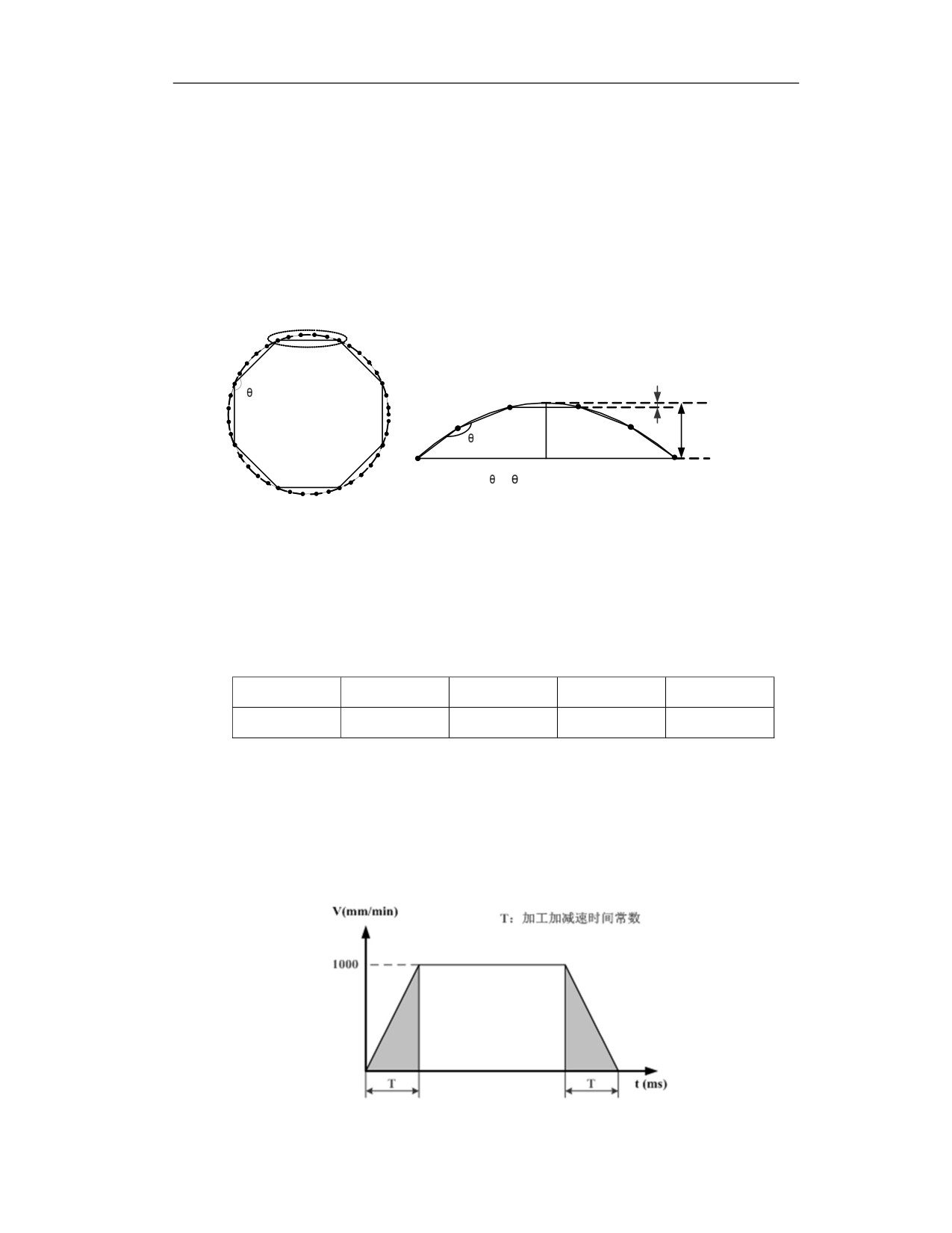
Spline curve refers to a curve obtained by a given set of control points, which can be used to
describe free curves and curved surfaces. It is specified as a CAD/CAM data exchange standard
by the International Organization for Standardization. The chord line is usually used for
approximating the arc at the time of spline curve interpolation, and the accuracy depends on the
number of the approximating chord. As shown in the figure below; the system interpolation period
is 1ms, and the system is specified to run a full circle in 8ms, then it will approximate the circle
to a regular octagon, and the servo position control period is 0.2ms. After the spline smoothing
function is turned on (100 is set), the full circle spline can be approximated to a regular 40-sided
polygon.
a-a
1=135°
△d2
△d1
158°
2=
2> 1 △d2 >△d1
图(a)
图(a-a)
After the spline is smoothed, the included angle of the spline segment becomes larger, which is
beneficial to reduce the speed fluctuation and improve the surface finish; the contour error is
greatly reduced compared with the previous one, which reduces the loss of precision and improves
the processing accuracy.
Machining acceleration/deceleration time constant
Parameter type
Parameter
Unit
Value range
Default value
Axis parameter
100038
ms
0~2000.0
32
"Machining acceleration/deceleration time constant" refers to the time for linear axis (G01, G02,
etc.) to accelerate from 0 to 1000mm/min or decelerate from 1000mm/min to 0, as shown in the
figure below (T represents the machining acceleration deceleration time constant). This parameter
determines the axis's processing acceleration. The larger the processing acceleration/ deceleration
time constant, the slower the acceleration/deceleration. This parameter is set based on the motor
inertia moment, the load inertia, and the acceleration capability of the drive.
381
The comparison table of common machining acceleration/deceleration time constant and
acceleration is as follows:
Machining
acceleration/dec
2ms
8 ms
16 ms
32 ms
64 ms
eleration time
constant
Acceleration
1g
0.2g
0.1g
0.05g
0.02g
Example: The machining acceleration/deceleration time constant is set to 6ms, then the processing
acceleration is calculated as follows:
1000mm/60s≈16.667mm/s
16.667/0.006≈2778mm/s2≈0.283g
(1g=9.8m/s2 )
Machining acceleration/deceleration jerk time constant
Parameter type
Parameter
Unit
Value range
Default value
Axis parameter
100039
ms
0~2000.0
128
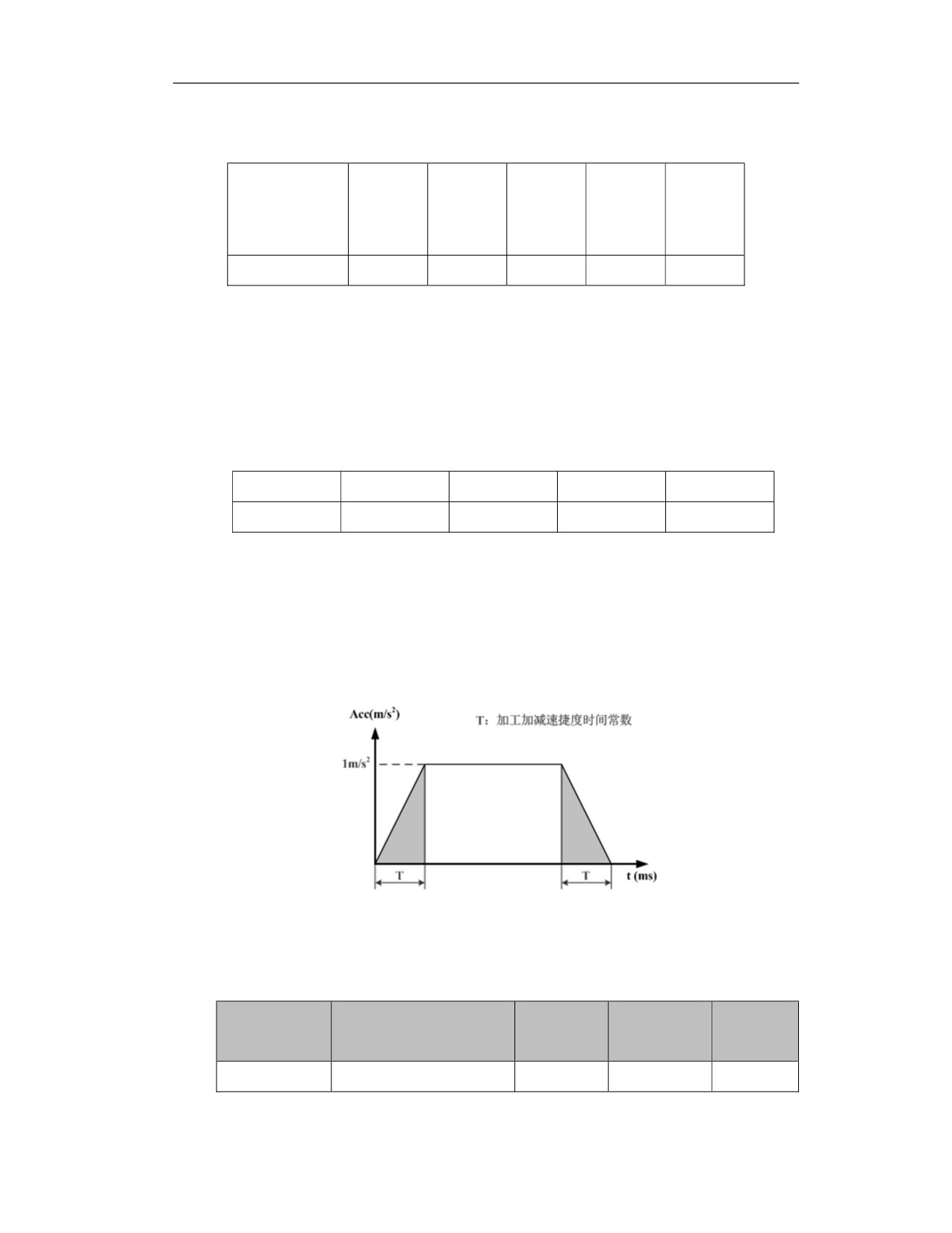
"Machining acceleration/deceleration jerk time constant" refers to the time when the acceleration
increases from 0 to 1m/s2 or decreases from 1m/s2 to 0 during axis machining movement (G01,
G02, etc.), as shown in the figure below (T represents the machining acceleration deceleration
jerk time constant). This parameter determines the machining jerk of the axis. The larger the time
constant, the smoother the acceleration changes. This parameter is set based on the motor, the
performance of the drive and the load, and is generally set between 8 and 150.
Example: Assuming that the processing acceleration is 0.05g (0.49m/s2) and the processing
acceleration/deceleration jerk time constant is set to 128ms, the jerk is 0.49/0.128≈3.8m/s3.
Machining acceleration time coefficient
Parameter type
Parameter
Unit
Value range
Default
value
Axis parameter
040156/040176/040196
-
0.01 to 100.0
1
Take the axis parameter "machining acceleration/deceleration time constant" as the reference
382
value, and use the "machining acceleration time coefficient" to convert the machining acceleration
/deceleration time to change the acceleration. The formula is as follows:
Converted value of machining acceleration/deceleration
time
= machining
acceleration/deceleration time constant * machining acceleration time coefficient
According to the characteristics of the processing program and the actual processing conditions,
this parameter can realize the flexible switching of the acceleration, and optimize the processing
efficiency or processing accuracy. When efficiency is the priority, this parameter can be
appropriately reduced; when accuracy is the priority, this parameter can be appropriately
increased.
Example: The machining acceleration/deceleration time constant is set to 8ms in the axis
parameters, and the corresponding acceleration is 0.2g. When the machining acceleration time
coefficient is 0.25, the machining acceleration/deceleration time is converted to 2ms, and the
corresponding acceleration becomes 1g.
Machining jerk time coefficient
Parameter type
Parameter
Unit
Value range
Default
value
Axis parameter
040157/040177/040197
-
0.01 to 100.0
1
Taking the axis parameter "machining acceleration/deceleration jerk time constant" as the
reference value, the machining acceleration/deceleration jerk time is converted through the
"machining jerk time coefficient" to change the time that the acceleration increases. The
conversion formula is as follows:
Converted value of machining jerk time = machining acceleration/deceleration jerk time constant
* machining acceleration time coefficient
Through this parameter, the acceleration speed can be flexibly switched, and the acceleration
change can be reasonably controlled to ensure the stability of the machining.
Example: Assuming that the current processing acceleration is 0.05g (0.49m/s2) and the axis
parameter "machining acceleration/deceleration jerk time constant" is set to 64ms, the jerk is
0.49/0.64≈7.6m/s3. When the machining acceleration time coefficient is 2, the converted value of
the machining acceleration/deceleration time is 128ms, and the corresponding jerk becomes 3.8
m/s3.
Example
In the actual CNC machining process, different machining processes and part contours will
produce parts processing procedures with their own characteristics, and different machining
requirements will also bring different control modes. Efficiency and precision are the two ends of
the balance of CNC machining. Therefore, only the combination of the above parameters can be
adjusted according to the specific processing object and customer needs, so that the efficiency
383
and accuracy can be biased or reach a suitable balance point, so that the overall processing effect
can be optimized. The following explains the combination adjustment of parameters through
practical application examples.
Cleanup machining parameter application
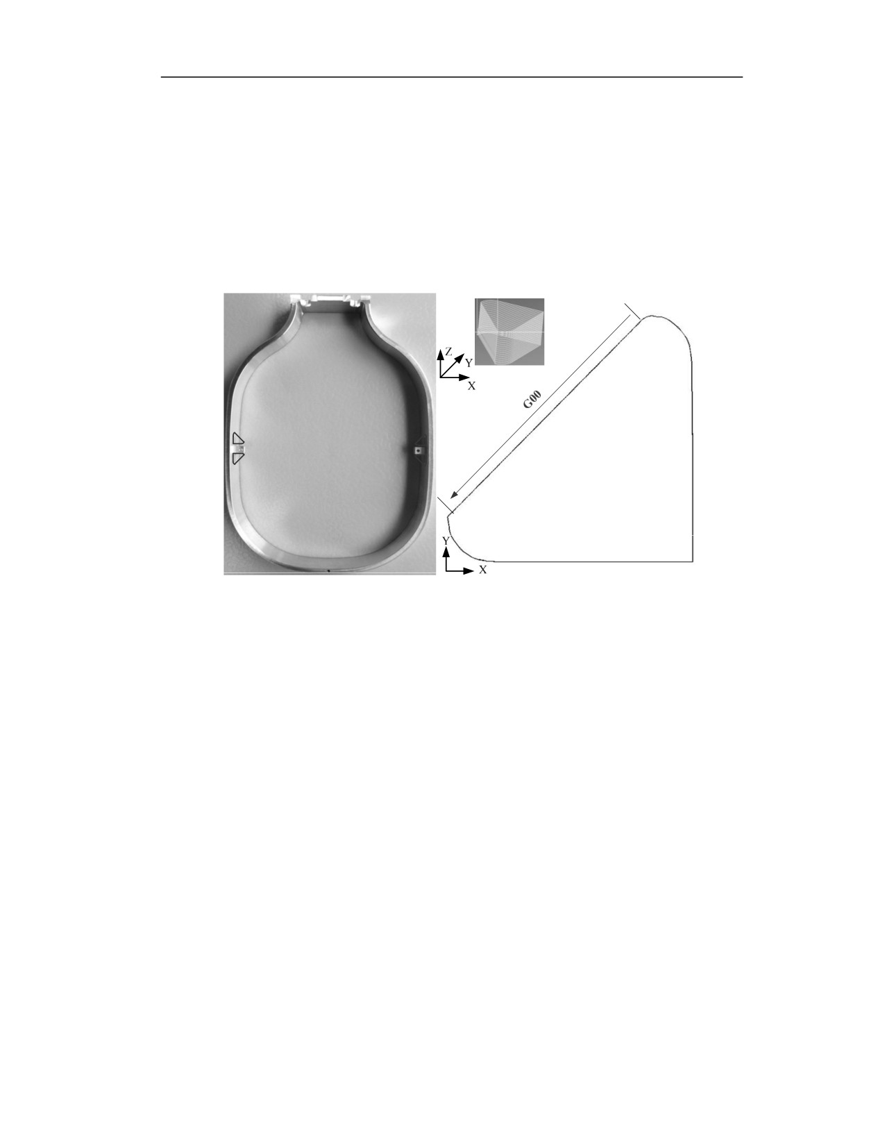
The cleanup machining is popular in 3C industries including mobile phone casings and circuit
board fixtures.
The contour path is shown as below
① In the actual processing process, the requirements for the cleanup machining efficiency is high,
that is, the processing time is as short as possible.
② It can be seen from the machining process and machining contour that the machining requires
high precision at 90-degree corners, and there is no actual effective cutting on the arc segment, so
there is no need to consider the contour accuracy.
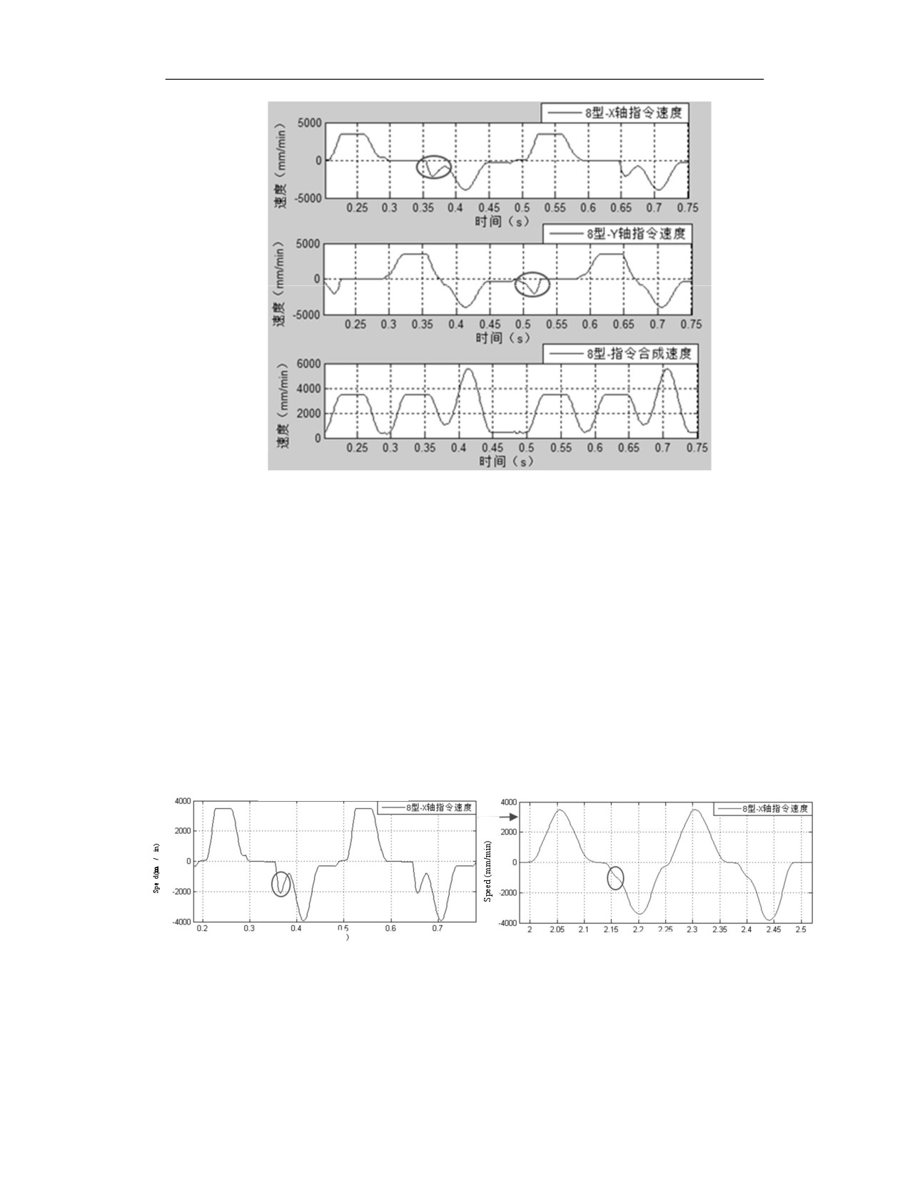
③ The overall machining contour is small, there are connections between straight lines and arcs,
as well as G00 and G01, the speed changes quickly, and the speed fluctuates greatly. As shown in
the figure below, the single-axis speed curve has a sudden change in speed. During the actual
processing, this sudden change in speed is the main cause of severe vibration of the machine tool.
384
Parameter combination application
① To meet the high-efficiency requirements of machining, improve the system's acceleration
capability, that is, reduce the machining acceleration/deceleration time constant and the
machining acceleration/deceleration jerk time constant to the suitable values, but the values
should not be too small to cause excessive acceleration and increase the vibration of the machine
tool. For example, when the acceleration time constant and the jerk time constant are 4 and 1, 2
and 2 respectively in the actual debugging, and the machining time is the same. However, when
the acceleration time constant is 2, the acceleration is too large and the machine vibration is severe,
so choose the appropriate acceleration time constant as 4.
② For the sudden change of single-axis, increase the command speed smoothing coefficient to
make the speed transition smoothly. As shown in the figure below, in the actual machining process,
when the command speed smoothing coefficient is 40, the machine vibration almost disappears.
Without command speed smoothing
Command speed smoothing periods: 40 (ms)
Time (s)
Time (s)
③ Since the accuracy of this machining arc is not high, the centripetal acceleration can be
increased, and the circular cutting feedrate can be increased; at the same time, in order to improve
the processing efficiency, reduce the minimum internal angle value of corner smoothing and
increase the corner deceleration factor to increase the feedrate at the corner.
385
Parameter setting
Parameter
Set value
Machining acceleration time
4
constant (ms)
Machining acceleration jerk time
1
constant (ms)
Command speed smoothing periods
40
(ms)
Min. interior angle of corner
80
smoothing(°)
Corner deceleration factor (%)
90
Centripetal acceleration (mm/s2)
6000
Combination application of laser processing parameters
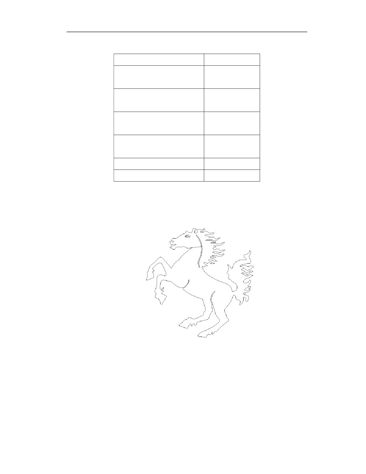
Laser cutting is widely used in contour processing. Take the "horse" contour as an example here;
The contour path is shown in the figure below:
Analysis of processing requirements and characteristics:
① It can be seen from the outline of the horse that it has hair shape processing on the horse head
and tail which need a large number of sharp corner processing, and the speed fluctuates greatly.
② According to the laser cutting processing requirements of the horse shape, when a certain
processing time is ensured, the sharp corners of the processing contour must be sharp, and there
is no rounded corners.
③ The processing speed is high and above F10000, and its acceleration is required to be close to
1g, but at the same time it is necessary to ensure that the machine vibration is small.
386

Parameter combination application
① For problems such as large speed fluctuations and strong machine tool vibration, and its sharp
corners are processed into a large number of small line segments, the spline smoothing function
is turned on to smooth the speed step changes in the high-speed section.
② Although the command speed smoothing function can effectively reduce speed fluctuations,
but the excessive large value will change the sharp corners to rounded corners, so the command
smoothing speed here should not be too high. In the actual debugging the value of 5 can reduce
machine vibration , improve efficiency without affecting the shape of horse's hair.
③ For the acceleration requirement of 1g, the machining acceleration time constant must be
reduced. The appropriate value is 2. However, the vibration of the machine tool increases due to
excessive acceleration changes. Therefore, the acceleration jerk time constant is reduced to lower
the acceleration change and increase the smoothness of the axis in the acceleration and
deceleration stages, reducting machine vibration.
④ The processed parts require high precision and processing time. Appropriately reduce the
centripetal acceleration so that the deceleration is performed at the small arc; increase the
minimum interior angle of corner smoothing to improve the corner contour accuracy; adjust the
appropriate corner deceleration factor to keep its value about 70, then the balance of accuracy and
efficiency is ensured.
Parameter setting reference value
Parameter
Set value
Machining acceleration time constant (ms)
2
Machining acceleration jerk time constant
10
(ms)
Command speed smoothing periods (ms)
5
Min. interior angle of corner smoothing
130
(°)
Corner deceleration factor (%)
70
Centripetal acceleration (mm/s2)
2500
Spline smoothing coefficient
100
Note
1) In HNC8 CNC system, multiple sets of small line segment control parameters are used to
achieve different parameter combination control, which includes the various control parameters
described above that play a major role in processing accuracy and efficiency.
2) As shown in the above example, according to the specific processing technology and processing
requirements, different parameter combinations are summarized to set the small line segment
387
control parameters of different groups. In actual processing, user only needs to call the
corresponding small line segment combination parameter command to complete the change of
control parameters, which can not only realize the combined use of multiple sets of control
parameters, but also complete the quick switching of different control parameter combinations.
Please find below for how to call the control parameter combinations.
G05.1 Q1 (The first group of small line segment control parameter combination)
……(Machining program 1)
G05.1 Q2 (The second group of small line segment control parameter combination)
……(Machining program 2)
G05.1 Q3 (The third group of small line segment control parameter combination)
……(Machining program 3)
388