HNC-818. User Manual - page 10
12. Fixed Cycle
1.
ǻI and ǻK indicates the total cutting amount during roughing. If the
roughing number is r, then each cutting amount in the X and Z
Attention
direction is ǻI/r and ǻK/r respectively.
2.
When executing this cycle based on the P and Q commands in G73,
pay attention to the symbols ("+" or "-") of ǻx, ǻz, ǻI and ǻK.
Example
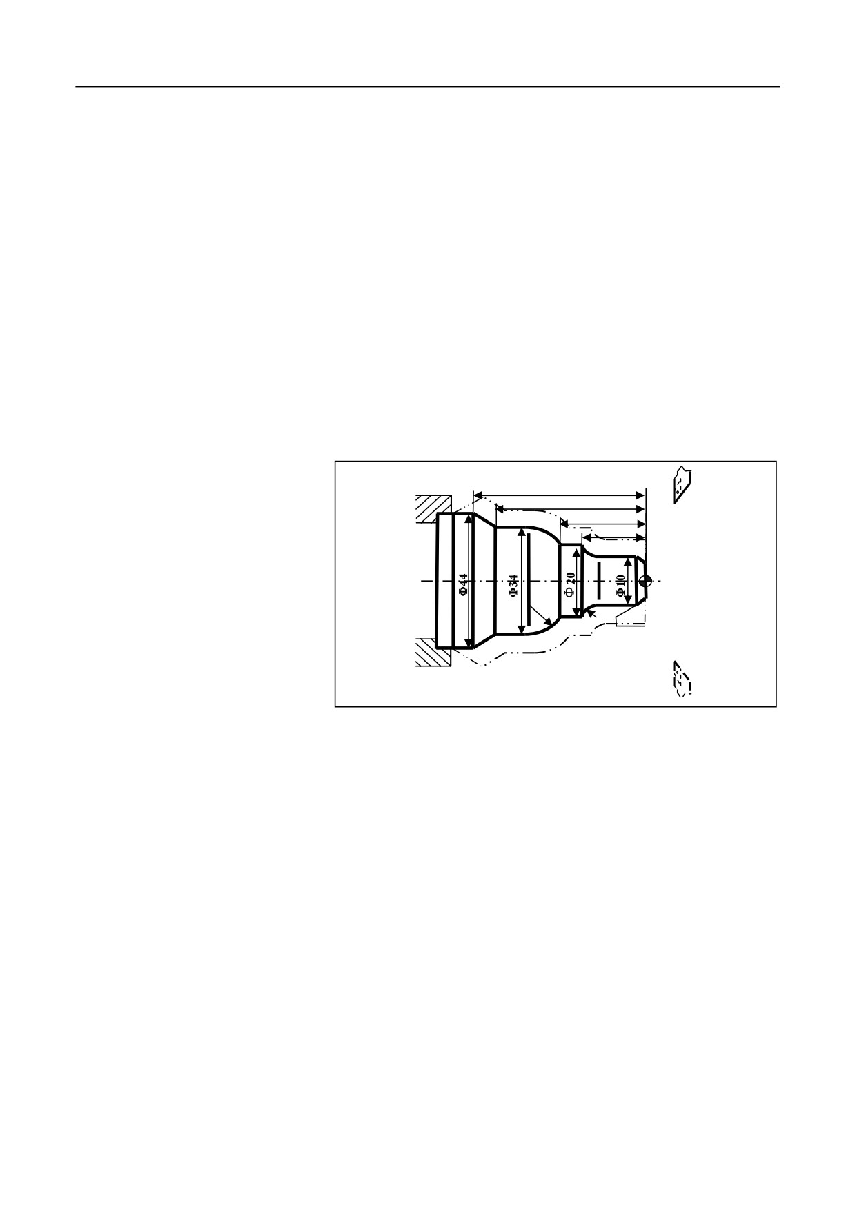
Create a machining program for the workpiece shown as below: cutting
start point: A (60, 5); roughing allowance along the X and Z axis: 3 mm
and 0.9 mm respectively; roughing count: 3. The finishing allowance
along the X and Z axis: 0.6 mm and 0.1 mm respectively. The dotted
lines indicate the workpiece.
62
52
35
25
R7
R5
2×45 degrees
%3330
N1 T010; Select No. 1 tool and define coordinate system
N2 G00 X80 Z80; Go to the program start point
N3 M03 S400; Rotate spindle in the clockwise direction at 400r/min
N4 G00 X60 Z5; Go to the cycle start point
N5 G73U3W0.9R3P6Q13X0.6Z0.1F120; Conduct machining with
closed rough cutting cycle
N6 G00 X0 Z3; Start finishing, go to the extended line of chamfer
N7 G01 U10 Z-2 F80; Conduct finishing for 2×45° chamfer
N8 Z-20; Conduct finishing for the outer circle of ĭ10
N9 G02 U10 W-5 R5; Conduct finishing for the arc of R5
N10 G01 Z-35; Conduct finishing for the outer circle of ĭ20
276
12. Fixed Cycle
N11 G03 U14 W-7 R7; Conduct finishing for the arc of R7
N12 G01 Z-52; Conduct finishing for the outer circle of ĭ34
N13 U10 W-10; Conduct finishing for the cone
N14 U10; Exit the machined face, complete finishing contour
N15 G00 X80 Z80; Back to the program start point
N16 M30; Stop spindle, end the main program, and reset
277
12. Fixed Cycle
12.4.4
Thread Cutting Compound Cycle (G76)
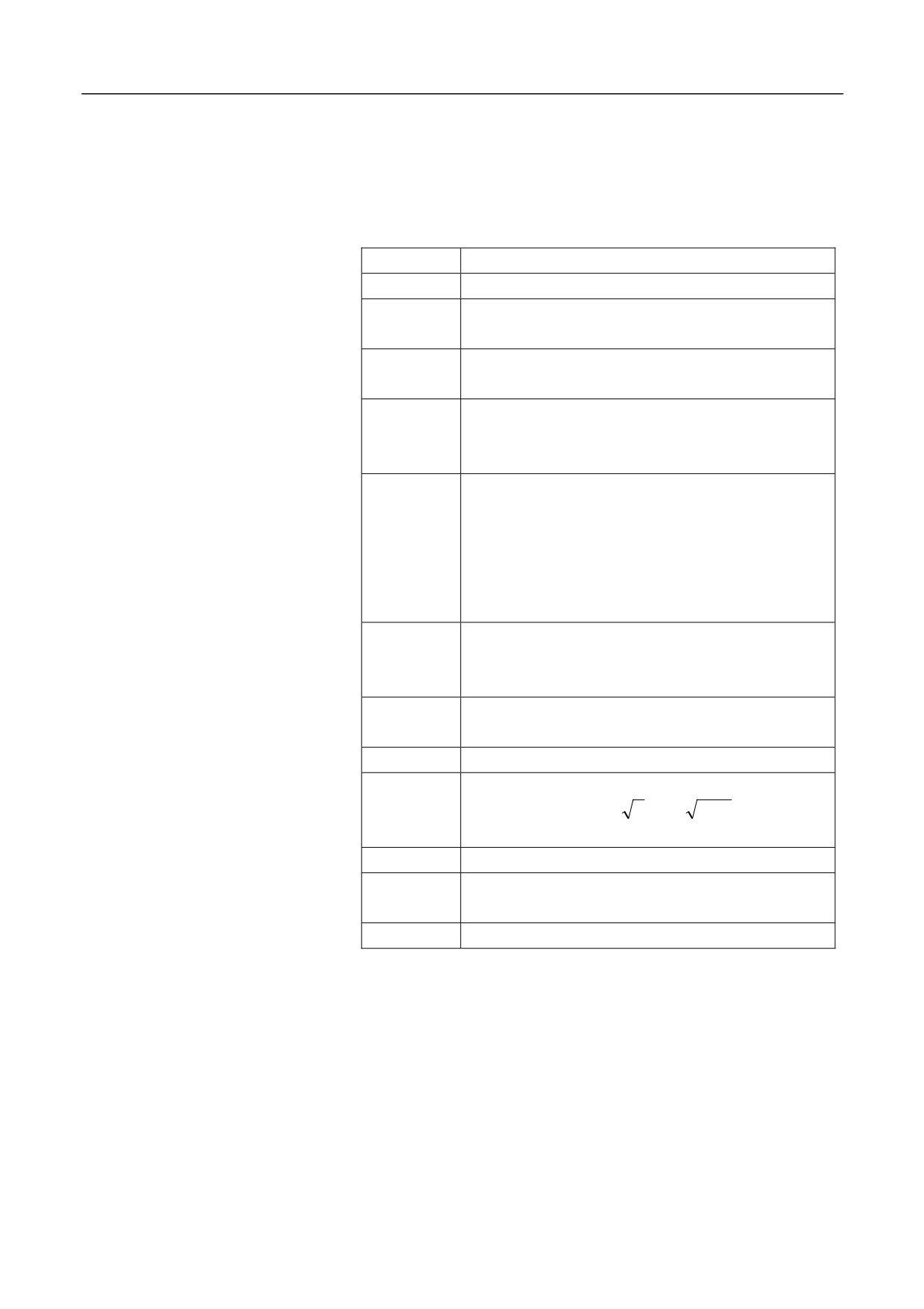
Format
G76
C(c) R(r) E(e) A(a) X(x) Z(z) I(i)
K(k) U(d) V(Δdmin) Q(Δd) P(p) F
Parameter
Description
C
Exact cutting count (1-99), modal value.
R
The retreat of tailstock along the Z axis during
threading, modal value.
E
The retreat of tailstock along the X axis during
threading; modal value.
A
The tool nose angle (two digits), modal value.
The value must be greater than 10 degrees and less
than 80 degrees.
X Z
The coodinates of the valid thread end point C for
absolute value programming; The relative distance
from the valid thread end point C to the cycle start
point A for the incremental value programming. ( the
G91 command for incremental programming, and the
G90 command for absolute value programming).
I
The radius difference between the ends of the thread.
If i
= 0, it indicates a straight thread
(cylindrical
thread) cutting mode.
K
Thread height. This value is specified by the radius
value in the X axis direction.
U
The finishing allowance (radius value).
V
The minimum cutting depth (radius value); when the
nth cutting depth Δd
n −Δd
n −1 is less than
Δdmin, the cutting depth is set to Δdmin.
Q
The first cutting depth (radius value)
P
The spindle rotation angle between the the spindle
reference pulse and the cutting start point.
F
Thread lead (same as G32); F indicates Metric.
Description
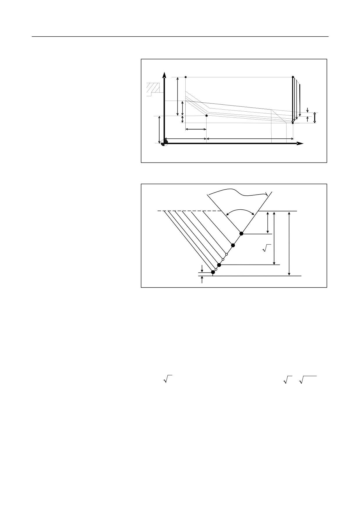
The thread cutting fixed cycle G76 can be used for the machining path
shown as below:
278
12. Fixed Cycle
+X
D
A
(R)
(R)
u/2
(R)
(F)
e
Δd
K
i
C
r
B
x/2
w
z
+Z
The unilateral cutting and related parameters are shown as below:
Į
ǻd
1
k
2
Δd
n
d
n
Attention
1.
When executing the cycle with the X(x) and Z(z) commands in G76,
pay attention to the sign ("+" or "-") of u and w (determined by the
direction of the tool path AC and CD) during incremental
programming.
2.
G76 can be used for unilateral cutting, reducing the force of the tool
nose. The first cutting depth is Δd; the total nth cutting depth is
Δd
n ; The depth of cut for each cycle is Δd(
n−
n−1).
3.
In the unilateral cutting figure, the cutting speed from B to C is
specified by the thread cutting speed, while other paths are all
defined by the feed speed.
Example
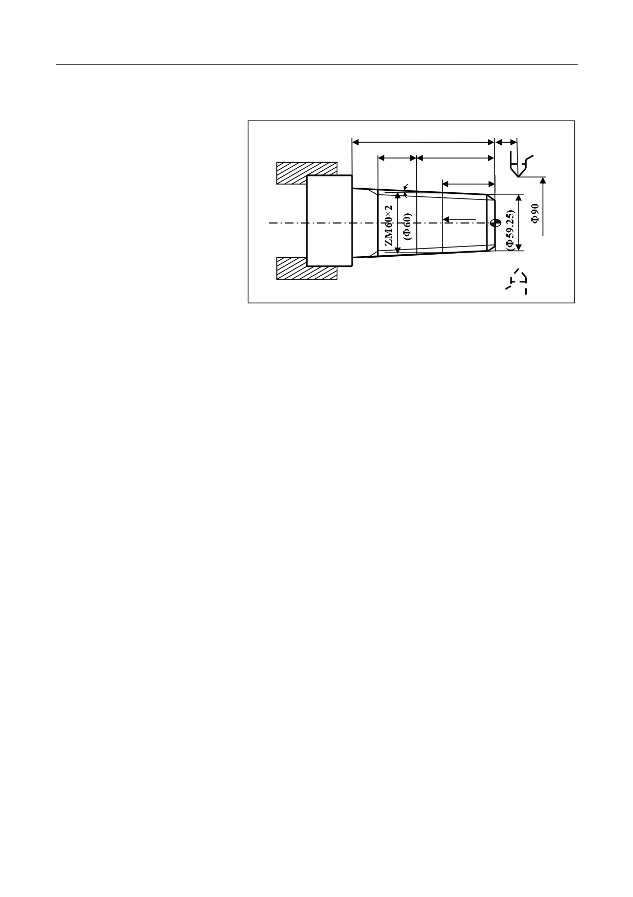
Use the thread cutting compound cycle command G76 to create a
program for the thread machining of ZM60×2. The dimension of the
279
12. Fixed Cycle
workpiece is shown as below. The size in the bracket is derived from the
threading standard. (tan1.79=0.03125)
30
4
(18)
6
Valid length
(1.79°)
(12)
Base plane
%3331
N1 T0101; Select No. 1 tool and define coordinate system
N2 G00 X100 Z100; Go to the program start point or tool exchange
position
N3 M03 S400; Rotate spindle in the clockwise direction at 400r/min
N4 G00 X90 Z4; Go to the simple cycle start point
N5 G80 X61.125 Z-30 I-1.063 F80; Conduct machining outer surface of
the conical thread
N6 G00 X100 Z100 M05; Go to the program start point or tool exchange
position
N7 T0202; Select No. 2 tool and define coordinate system
N8 M03 S300; Rotate spindle in the clockwise direction at 300r/min
N9 G00 X90 Z4; Go to the thread cycle start point
N10 G76C2R-3E1.3A60X58.15Z-24I-0.875K1.299U0.1V0.1Q0.45F2
N11 G00 X100 Z100; Return to the program start point or tool exchange
position
N12 M05; Stop spindle
N13 M30; End the main program, and reset
280

12. Fixed Cycle
12.5
Special Cases in Fixed Cycle
For milling machines, use G80 to cancel the fixed cycle. For turning
machines, use G00/G01/G02 to cancel the fixed cycle. After the fixed
cycle statement, all statements are identified by the system as a fixed
cycle before the fixed cycle is canceled.
Wrong programming
Correct programming
%1111
%1111
T0101
T0101
G0X50Z20
G0X50Z20
X32Z0
X32Z0
G80X30Z-30
G80X30Z-30
M98P12; Call %12 in the fixed
G01
cycle
M98P12; call %12 of the current
M30
program
%12
M30
G0X10Z10
%12
X30Z30
G0X10Z10
M99
X30Z30
M99
Currently, the fixed cycle cannot
be used with rotation, mirroring,
scaling, and G91 simultaneously.
281
13. User Macro Program
13 User Macro Program
User macro program is similar to a high-level language programming
method, which allows users to use variables, arithmetic, logical
operations and conditional transfer. This function makes it simpler to
create the same machining program than the traditional ones. Users may
create general macro program for the same machining operation, e.g. the
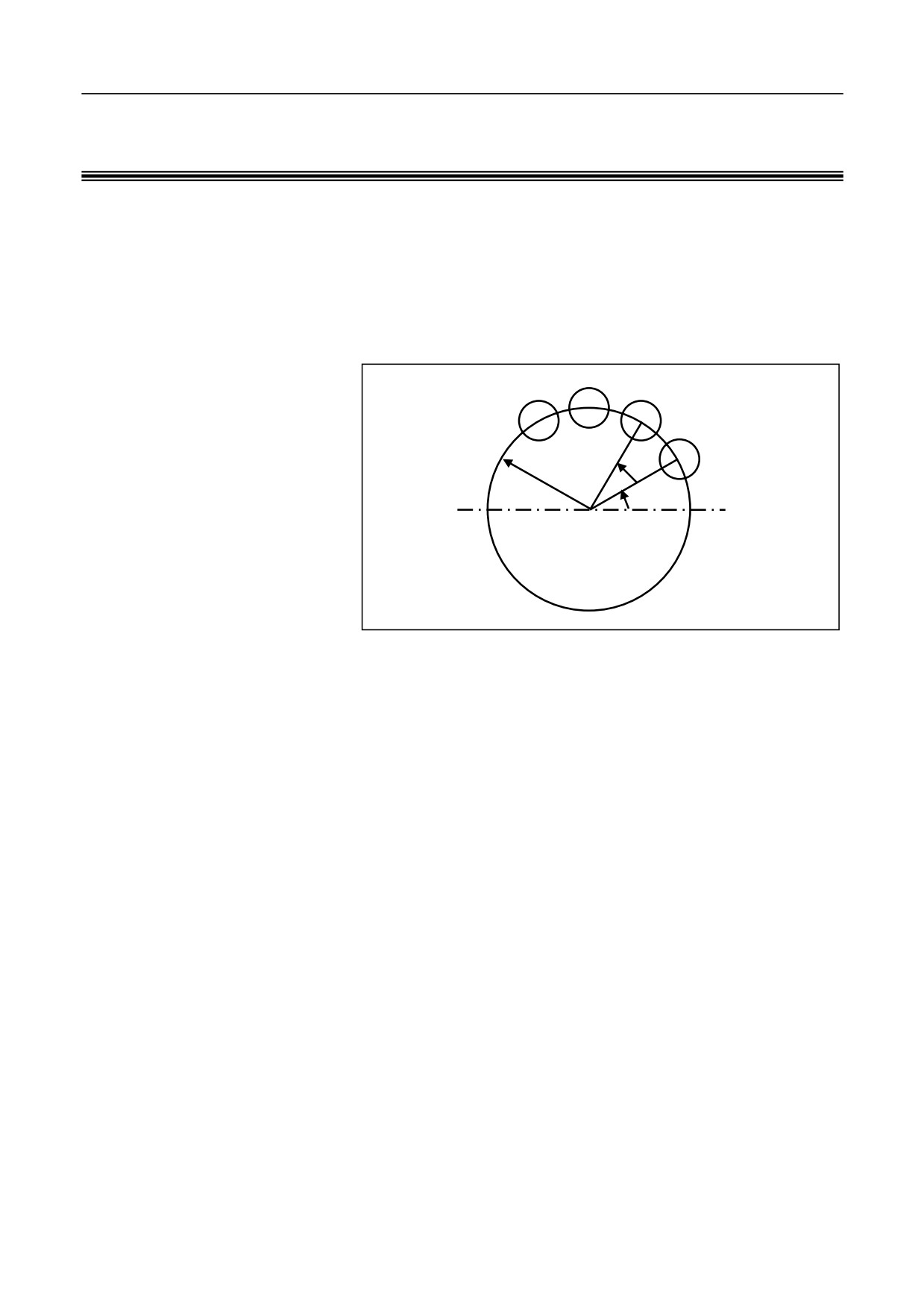
machining of the bolt hole circle shown as below:
b
r
a
Create a macro program for the bolt hole circle machining shown in the
figure above, and store it in the CNC. This way, you can call this
program to machine the bolt hole circle at any time by simply entering
the bolt hole properties such as the number of holes and deviation angle.
It is like a bolt hole circle function is added to the CNC.
13.1 Variables
13.2 Operation Instructions
13.3 Macro Statement
13.4 Macro Program Calling
13.5 User Sub-Programs
282
13. User Macro Program
13.1 Variables
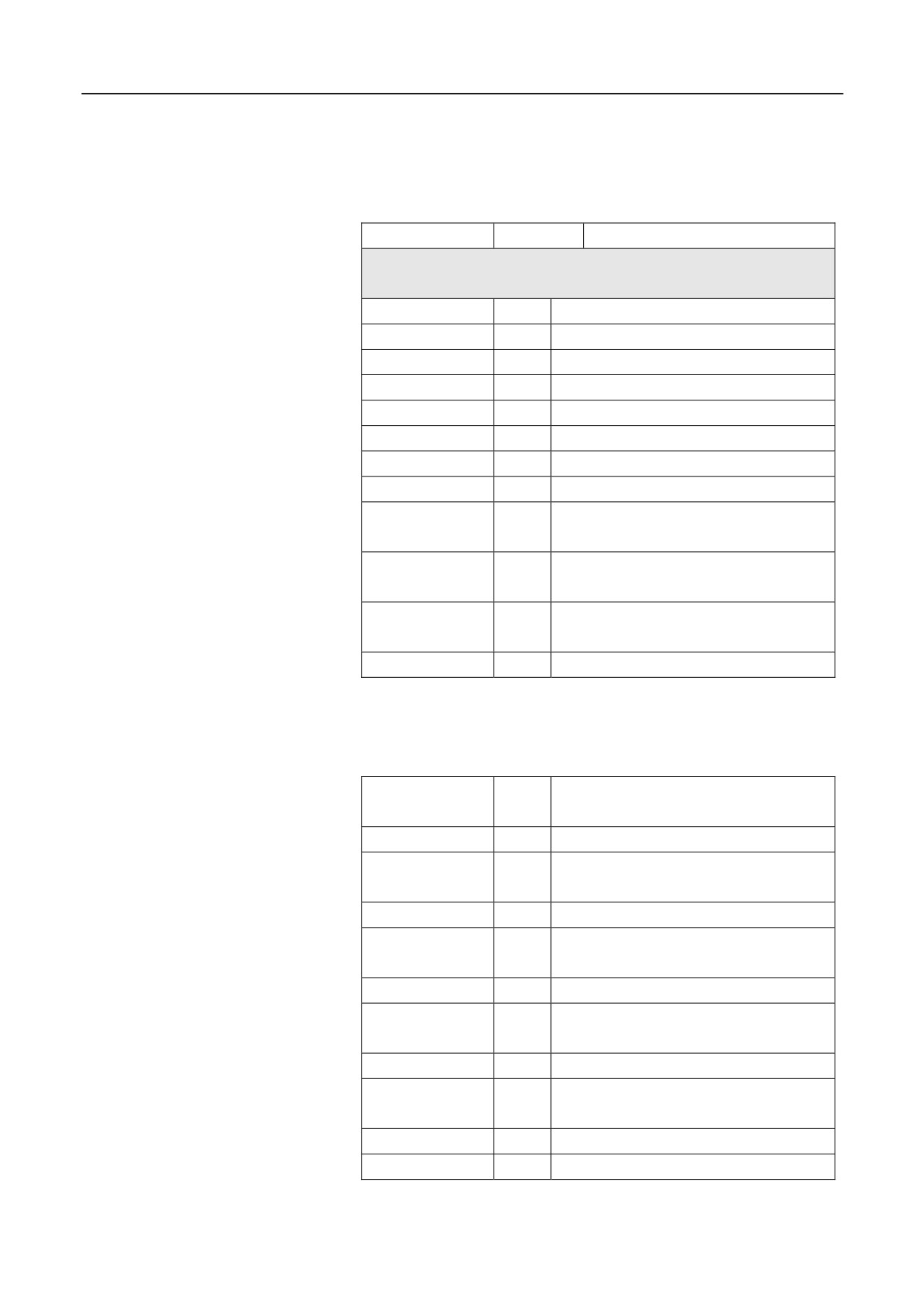
In a macro program, you may use variables for parameters of preparation
function commands and axial movement distance, e.g. G00 X[#43],
where #43 is a variable. You can assign to it before calling it.
Attention
In macro program, you cannot directly use the variable name. Variables
is specified with the variable symbol
(#) and the variable number
following the symbol.
Variables
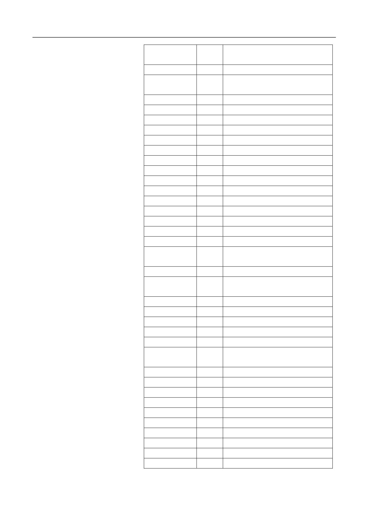
According to the variable numbers, variables can be divided into local
variables, global variables, and system variables. Different variables
have different usages. In addition, the access properties of different
variables are different; some variables are read-only.
Constant
A number of constants have been defined for users in the system, which
are read-only.
PI: circular constant Ȇ
TRUE: indicates the condition is true.
FALSE: indicates the condition is false.
Attention
When using the constant PI, users need to specially handle the end
condition of the program because of its calculation error; otherwise,
exceptions may occur.
Local variables
Local variables are variables used within the macro program. That means
a local variable (e.g. #i) called from a macro program A at one time is
different from that at another time. Therefore, during multi-layer calling,
the system may improperly use in macro B the local variables being used
in macro A when calling macro B from A, resulting in damage to the
value.
Variables from #0 to #49 are local variables, of which properties are read
and write.
283
13. User Macro Program
The system provides six layers of nested local variables, of which
properties are read-only.
•
#200-#249: local variables of layer 0
•
#250-#299: local variables of layer 1
•
#300-#349: local variables of layer 2
•
#350-#399: local variables of layer 3
•
#400-#449: local variables of layer 4
•
#450-#499: local variables of layer 5
Global variables
variables can be generally used for the main program calling
subprograms, or used among subprograms and macro programs, while
the values remain unchanged. That means a global variable (e.g. #i) used
in one macro program and others is the same. In addition, the public
variable #i out of a macro can be used in other macros.
Variables from #50 to #199 are global variables, of which properties are
read and write.
Different from local variables, global
System variables
System variables are fixed variables in the system. Its properties are
read-only, write-only and read &write, depending on the properties of
each system.
Undefined variables
The default value for the variables undefined in the system is 0.
Example:
%1234
G54
G01 X10Y10
X[#1]Y30; Coordinate value of the workpiece coordinate system (0, 30)
M30
284
13. User Macro Program
Variable No.
Properties
Description
Channel variables
Channel 00: (00000-03999)
#0 to #49
R/W
Current local variables
#50 to #199
Reserved
Variables related to channels
#200 to #249
R
Local variables of layer 0
#250 to 299
R
Local variables of layer 1
#300 to #349
R
Local variables of layer 2
#350 to #399
R
Local variables of layer 3
#400 to #449
R
Local variables of layer 4
#450 to #499
R
Local variables of layer 5
#1000 to #1008
R
Machine position of the current channel
axis (9-axis)
#1009
R
Diameter programming for turning
machines
#1010 to #1018
R
Programmed machine position of the
current channel axis (9-axis)
#1019
Reserved
#1020 to #1028
R
Programmed workpiece position of the
current channel axis (9-axis)
#1029
Reserved
#1030 to #1038
R
Workpiece origin of the current channel
axis (9-axis)
#1039
R
Coordinate system
#1040 to #1048
R/W
G54 origin of the current channel axis
(9-axis)
#1049
R
G54 axis mask
#1050 to #1058
R/W
G55 origin of the current channel axis
(9-axis)
#1059
R
G55 axis mask
#1060 to #1068
R/W
G56 origin of the current channel axis
(9-axis)
#1069
R
G56 axis mask
#1070 to #1078
R/W
G57 origin of the current channel axis
285

13. User Macro Program
(9-axis)
#1079
R
G57 axis mask
#1080 to #1088
R/W
G58 origin of the current channel axis
(9-axis)
#1089
R
G58 axis mask
#1090 to #1098
R/W
G59 origin of the current channel axis
(9-axis)
#1099
R
G59 axis mask
286
13. User Macro Program
#1100 to #1108
R
G92 origin of the current channel axis
(9-axis)
#1109
R
G92 axis mask
#1110 to #1118
R
Breakpoint of the current channel axis
(9-axis)
#1119
R
Breakpoint axis labels
#1120 to #1149
R/W
Fixed cycle modal variables
#1150 to #1189
R
G code 0-39 modal
#1190
R
User-defined input
#1191
R
User-defined output
#1192 to #1199
Reserved
#1200 to #1209
R
AD input
#1210 to #1219
R
DA output
#1220
R
M3/4/5
#1221
R
G94 F value
#1222
R
Tapping F value
#1223 to #1226
R
Tapping spindle rotation speed
#1227
R
Valid radius compensation No. D
#1228
R
Valid length compensation No.H
#1229
R
cmd_feed
#1300 to #1308
R
Relative origin of the current channel
axis (9-axis)
#1309
Reserved
#1310 to 1318
R
Programmed machine position of the
current channel axis (9-axis)
#1319
Reserved
#1320 to #1328
R
G28 midpoint
#1329
R
G28 axis mask
#1330 to #1338
R
G52 origin
#1339
Reserved
#1340 to #1349
R
G31 measure machine command
position
#1350 to #1359
Reserved
#1360 to #1369
R
G31 measure actual machine position
#1370 to #1399
Reserved
#1400 to #1408
R/W
G54 offset
#1409
Reserved
#1410 to #1418
R/W
G55 offset
#1419
Reserved
#1420 to #1428
R/W
G56 offset
#1429
Reserved
#1430 to #1438
R/W
G57 offset
287
13. User Macro Program
#1439
Reserved
#1440~#1448
R/W
G58 offset
#1449
Reserved
#1450~#1458
R/W
G59 offset
#1459~#3999
Reserved
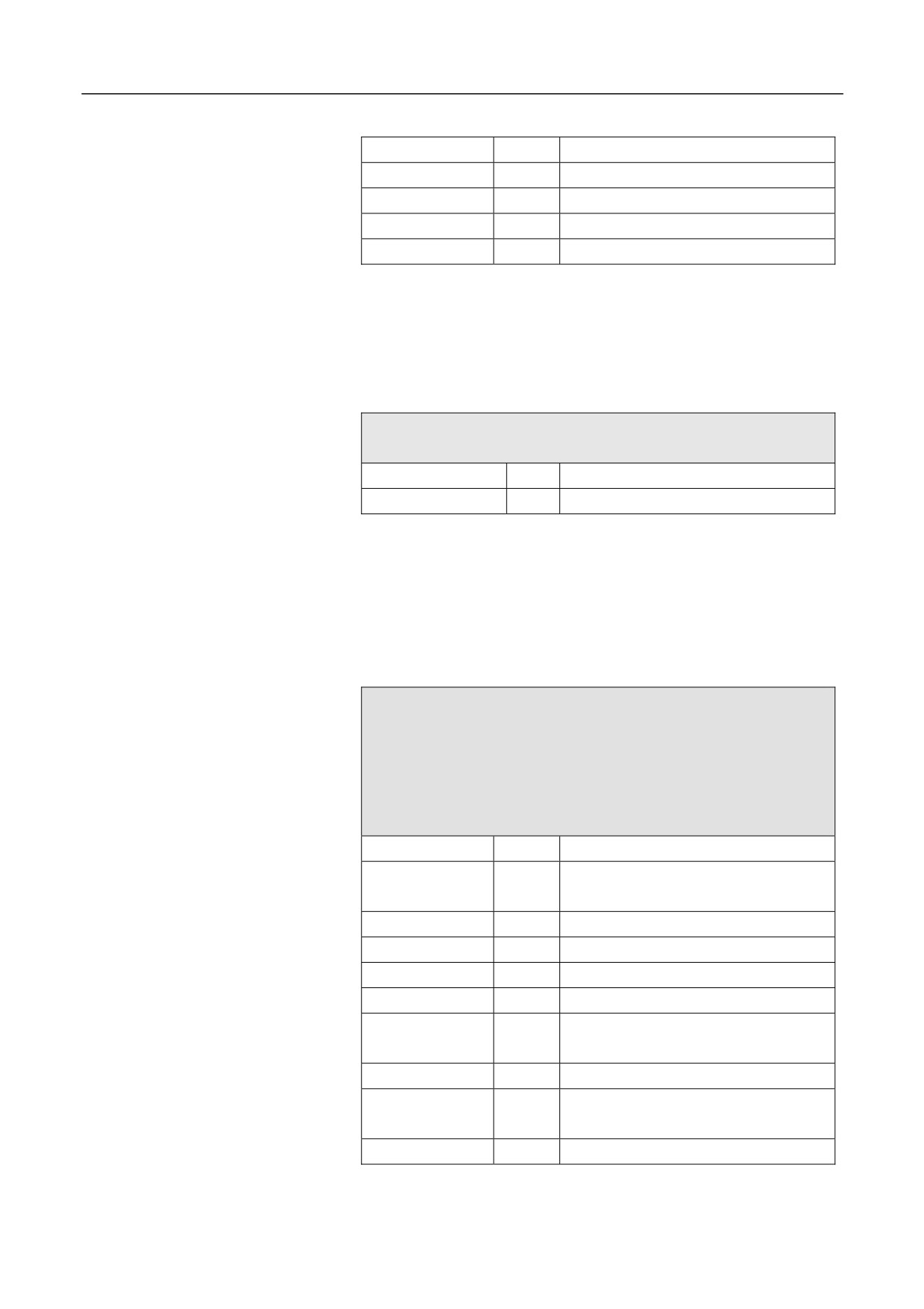
Attention
The variables corresponding to the origins and offsets of the current
channel workpiece coordinate system G54~G59 are read and write, and
can be saved after power off.
User-defined variables
User-defined variables: 500 to 999
50000 to 54999
#500 to #999
R/W
Global variables
#50000 to #54999
R/W
Global variables
Attention
When the machine user parameter 010091"#500~#999USER MACRO
ENABLED" is 1, the user-defined variables #500 to #999 are valid.
User-defined variables are saved after power off.
Variables related to tool
Tool data: #70000 to #89999
Each tool uses 200 numbers. There is a total of 100 tools, with a total
of 20000 numbers.
Coding range corresponding to No. 0 tool: 000 to 199
Coding range corresponding to No. 1 tool: 200 to 399
Coding range corresponding to No. 99 tool:18000-19999
#70005
R
The direction of the turning tool nose.
#70006
R/W
The length of the milling tool or the X
offset of the turning tool.
#70007
R
The Y offset of the turning tool.
#70008
R
The Z offset of the turning tool.
#70009
Reserved
#70010
Reserved
#70011
R/W
The radius of the milling tool or the
radius of the turning tool nose.
#70012-#70028
Reserved
#70029
R/W
The length wear of the milling tool or
the Z offset wear of the turning tool.
#70030
The Y offset wear of the turning tool.
288

13. User Macro Program
#70034
R/W
The radius wear of the milling tool or
the X offset wear of the turning tool.
#70035- #70100
Reserved
#70101
R
Tool life monitoring types
#70104
R
Maximum cutting time
#70105
R
Alarm cutting time
#70106
R
Acutal cutting time
#70107
R
Maximum cutting count
#70108
R
Alarm cutting count
#70109
R
Actual cutting count
The properties of the variables corresponding to the tool radius
Attention
compensation value, length offset, and wear values are read and write,
which can be save after power off.
289
13. User Macro Program
13.2
Operation Instructions
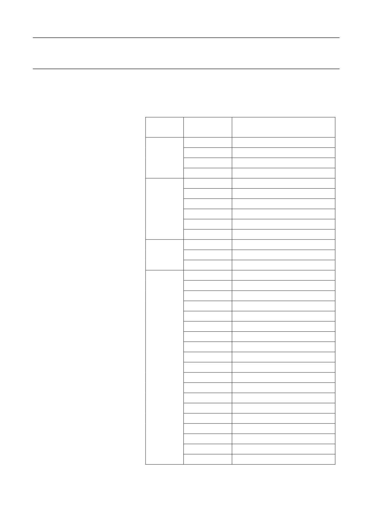
In the macro statement, you may flexibly use arithmetic operators and
functions to meet complex programming requirements. See the figure
below:
Operation
Operation
Description
Type
Instructions
#i = #i + #j
Addition, #i plus #j
Arithmetic
#i = #i - #j
Subtraction, #i minus #j
operation
#i = #i * #j
Multiplication, #i times #j
#i = #i / #j
Division, #i divided by #j
#i EQ #j
Equal to (=)
#i NE #j
Not equal to ( )
Condition
#i GT #j
Greater than (>)
operation
#i GE #j
Greater than and equal to ()
#i LT #j
Less than (<)
#i LE #j
Less than and equal to ()
#i = #i & #j
Logical operation "And"
Logical
#i = #i | #j
Logical operation "Or"
operation
#i = ~#i
Logical operation "Not"
#i= SIN[#i]
Sine (unit: radian)
#i=ASIN[#i]
Anti-sine
#i=COS[#i]
Cos (unit: radian)
#i=ACOS[#i]
Anti-cos
#i=TAN[#i]
Tangent (unit: radian)
#i=ATAN[#i]
Anti-tangent
#i=ABS[#i]
Absolute value
#i=INT[#i]
Integer (round down)
#i=SIGN[#i]
Obtain sign
Functions
#i=SQRT[#i]
Square root
#i=POW[#i]
Power
#i=LOG[#i]
logarithm
#i=PTM[#i]
Pulse time modulation (mm)
#i=PTD[#i]
Pulse time degree
#i=RECIP[#i]
Reciprocal
#i=EXP[#i]
Index based on e (2.718)
#i=ROUND[#i]
Round
#i=FIX[#i]
Round down
#i=FUP[#i]
Round up
290
13. User Macro Program
Example
The program below is used to obtain the sum of 1 to 10:
O9500
#1=0; The initial value of the subtrahend
#2=1; The initial value of the addend
N1 IF[#2 LE 10]; The addend cannot exceed 10; otherwise, it goes to the
N2 after ENDIF.
#1 =#1 + #2; Subtraction operation
#2 =#2 +1; The next addend
ENDIF; Move to N1
N2 M30; End program
291
13. User Macro Program
13.3 Macro Statement
Expression
Those calculation formulas with symbols like "+", "-", "*", "/", "[", "]",
and SIN are known as expression. See the examples as below:
1.
-#1
2.
SIN[#1+#2]*COS[[#1+#2]/#3]
Attention:
1.
The symbol "[ ]" indicates a higher priority than "+", "-", "*", and
"/". E.g. when conducting operation for
[[#1+#2]/#3], firstly
calculate the [#1+#2], then calculate /#3.
2.
For the expression, to ensure the calculation accuracy, it is
recommended to use the symbol "[
]", e.g.
[-#2]. It is not
recommended to write like -[#2].
Assignment statement
Assignment means to transfer the value of a constant or an expression to
a macro variable. This statement is called an assignment statement. See
the example below:
#2 = 175 / SQRT[2] * COS[55*PI/180]
#3 = 124.0
Condition statements
Two types of condition statement are supported in this system:
IF [condition expression];
Type 1
……
ENDIF
IF [condition expression];
Type 2
……
292
13. User Macro Program
ELSE
……
For the condition expression of the IF statement, you may use a simple
or complex expression. See the examples below:
ENDIF
When #1 is equal to #2, 0 is assigned to #3.
IF [#1 EQ #2]
#3 = 0
ENDIF
When #1 is equal to #2, and #3 is equal to #4, 0 is assigned to #3.
IF [#1 EQ #2] AND [#3 EQ #4]
#3 = 0
ENDIF
When #1 is equal to #2, or #3 is equal to #4, 0 is assigned to #3.
Otherwise, 1 is assigned to #3.
IF [#1 EQ #2] OR [#3 EQ #4]
#3 = 0
ELSE
#3 = 1
ENDIF
Cycle statement
Specify a condition expression after WHILE. When the specified
condition expression is satisfied, execute the programs between WHILE
to ENDW. When the specified condition expression is not satisfied, exit
the WHILE cycle, and execute the program line after ENDW.
Calling format:
WHILE [condition expression]
……
ENDW
Infinite cycle
293
13. User Macro Program
When the WHILE condition
expression is defined as always true,
WHILE [TRUE]; or WHILE [1]
an infinite cycle can be realized:
……
ENDW
GOTO statement
GOTO _
Use GOTO to move to the specified label.
GOTO must be followed by numbers. E.g. GOTO 4 indicates to move to
the N4 program block (N4 must be defined at the header of the program
block).
Nest
For the IF and WHILE statement, the system allows nested statements
that follow a certain of restrictive rules.
For IF statement, only up to six layers of nested statements are allowed;
if over six, an error will be reported.
For WHILE statement, only up to six layers of nested statements are
allowed; if over six, an error will be reported.
The system supports combined IF and WHILE statements, but the
matching relationship of IF-ENDIF and WHILE-ENDW must be
satisfied. For the usage as described below, the system will report an
error.
IF [condition expression 1]
WHILE [condition expression 2]
ENDIF
ENDW
Example
294
13. User Macro Program
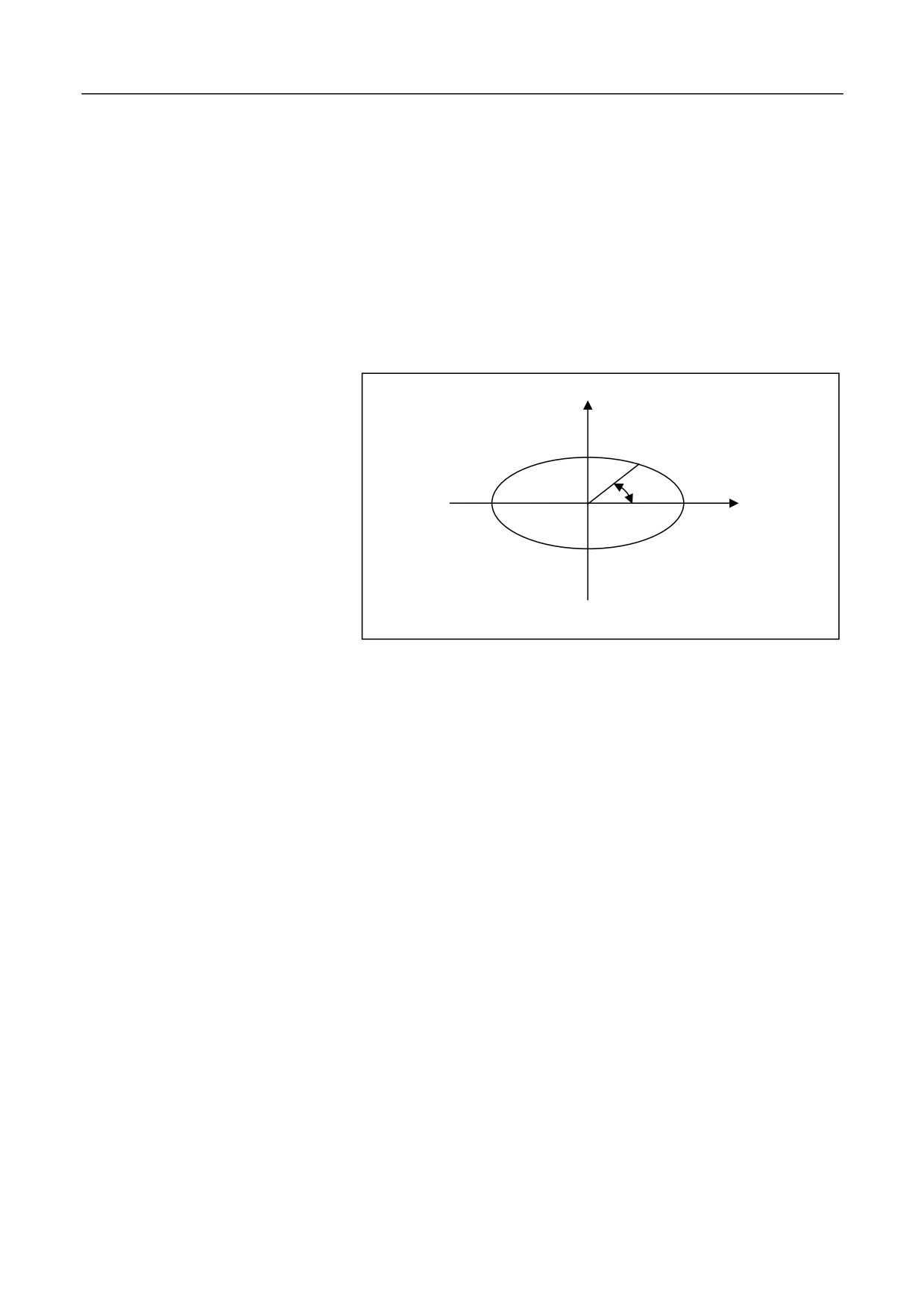
Edit ellipse machining program
(elliptic expression: X=a×COSĮ; Y
=b×SINĮ).
Į
%0001
#0=5; Define tool radius R
#1=20; Define a
#2=10; Define b
#3=0; Define the initial value of the stepping angle. unit: degree
N1 G92 X0 Y0 Z10
N2 G00 X[2*#0+#1] Y[2*#0+#2]
N3 G01 Z0
N4 G41 X[#1] D01
N5 WHILE #3 GE [-360]
N6 G01 X[#1*COS[#3*PI/180]] Y[#2*SIN[#3*PI/180]]
N7 #3=#3-5
ENDW
G01 G91 Y[-2*#0]
G90 G00 Z10
295
13. User Macro Program
G40 X0 Y0
M30
296
13. User Macro Program
13.4 Calling Macro Programs
There are three modes to call macro programs:
1.
Non-modal call: G65
2.
G-code call: fixed cycle
3.
Call subprograms with M codes
13.4.1 Rules for Defining Arguments
Rules for defining arguments
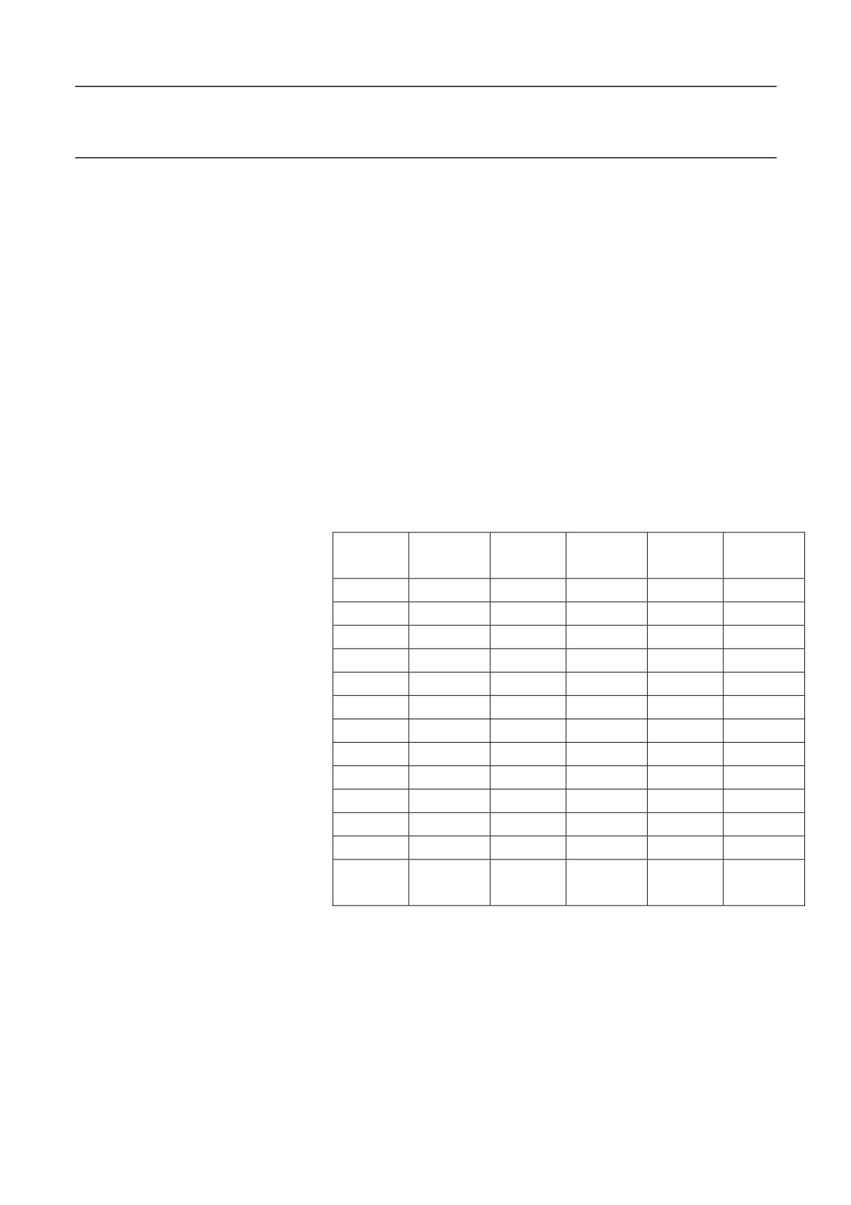
When users call the macro, the system will automatically copy the
argument (A - Z) in the current program to the local variables (#0 to #25)
of the current layer in the corresponding user macro, and copy the
workpiece coordinate system absolute position of the current channel
axis (XYZABCUVW) to the local variables (#30 to #38) of the current
channels.
Macro
Argument
Macro
Argument
Macro
Argument
Variables
Name
Variables
Name
Variables
Name
#0
A
#1
B
#2
C
#3
D
#4
E
#5
F
#6
G
#7
H
#8
I
#9
J
#10
K
#11
L
#12
M
#13
N
#14
O
#15
P
#16
Q
#17
R
#18
S
#19
Blank
#20
U
#21
V
#22
W
#23
X
#24
Y
#25
Z
#26
Reserved
#27
Reserved
#28
Reserved
#29
Reserved
#30
X position
#31
Y position
#32
Z position
#33
A position
#34
B position
#35
C position
W
#36
U position
#37
V position
#38
position
Example
%1234; Main program
G92 X0 Y0 Z50
G91 G01 Z10 F400
297
13. User Macro Program
M98 P111
G4X1
%111
G01x10y10z10
…
M99
Verification of macro definition
Format: AR[# variable number]
Returned value:
0: The variable is not defined.
90: The variable is defined as the absolute mode G90.
91: The variable is defined as the incremental mode G91.
Note: Use the system macro AR[] to determine whether the macro
variable is defined, and whether it is defined as the incremental or
absolute mode.
Example
%1234
G92X0Y0Z0
M98P9990X20Y30Z40
M30
%9990
IF [AR[#23] EQ 0] OR [AR[#24] EQ 0] OR [AR[#25] EQ 0]; if X or Y
or Z is not defined, then return
M99
ENDIF
G91; create macro program with the incremental mode
IF AR[#23] EQ 90; if the X value is the absolute mode G90
#23=#23-#30; change the X value to the incremental mode; #30 is the
absolute coordinate of X
ENDIF
……..
M99
298
13. User Macro Program
13.4.2 Non-Modal Call (G65)
When G65 is specified, the defined user macro program following the
parameter P is called. At the same time, the arguments and variables
required by the user macro program are transferred to the user macro
program.
Format
G65 P_ L_ [argument address word]
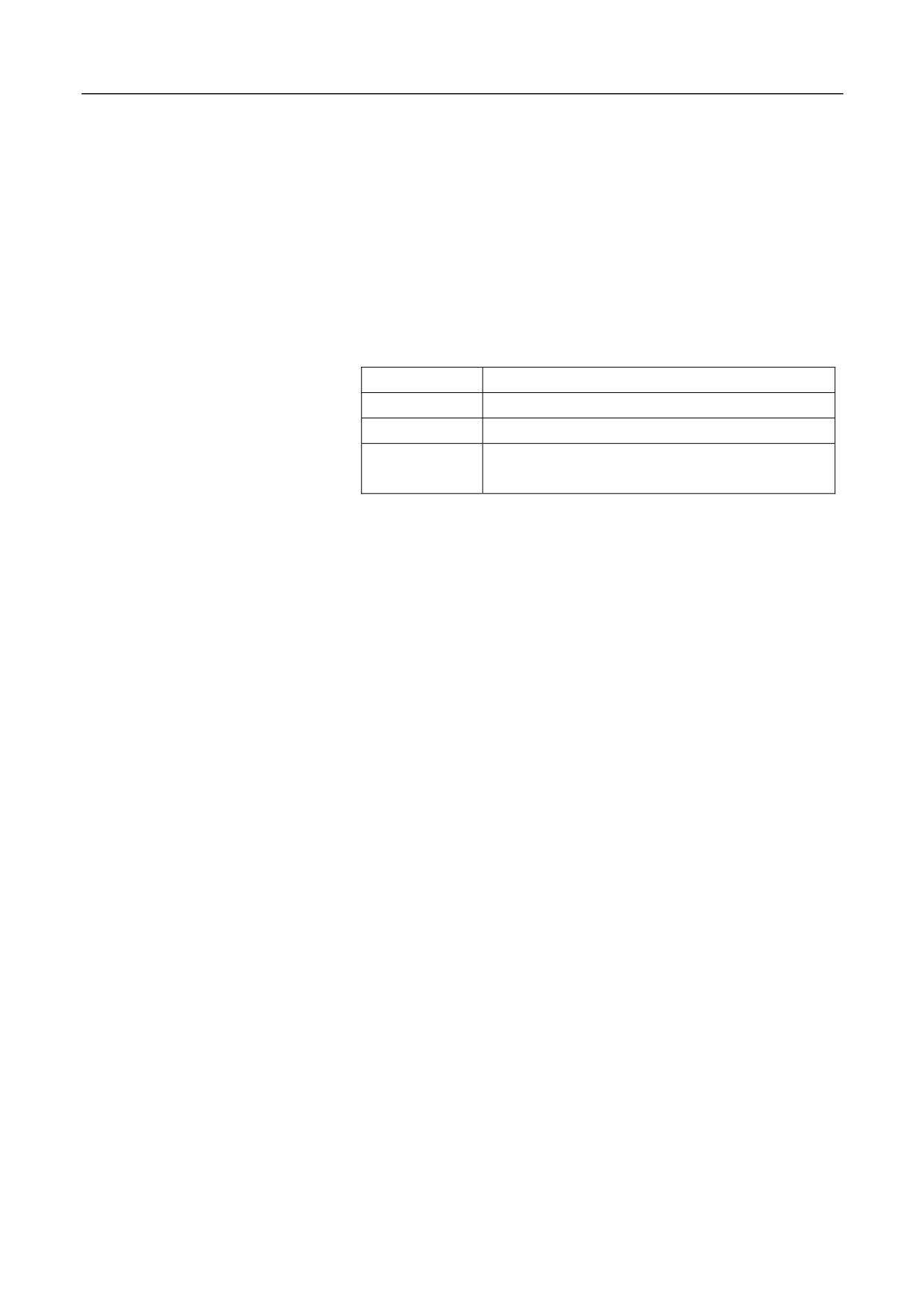
Parameter
Description
P
The number of the program to be called.
L
Call repeats.
Argument
The data that users need to transfer to the macro
address word
program.
Attention
1.
G65 is a non-modal command. You need to specify G65 in the
current line when calling macro programs.
2.
Subprograms must be in the same file.
Example
%0032
G54G0X100Z100
G65P100L5X50Z-30F1000
G00X50Z10
M30
%100
G01X[#23]Z[#25]F[#5]
G81X[#23]Z[#25]
G0X100Z50
M30
13.4.3 Call Macro Program with G Codes
299
13. User Macro Program
to call macro programs, you may call macro programs with G codes.
Currently, only the G codes in the
fixed cycle can be used to call macro programs. For details, see relevant
sections related to turning and milling operations.
In addition to use non-modal (G65)
Function
Use G codes to call the user-defined subprograms in the fixed cycle.
Format
G_
Parameter
Description
G
The subprogram number called in the
USERDEF.CYC (Arabic numerals).
Example
Add a fixed cycle 1001 in USERDEF.CYC
%1001;
G01 X10 Y10 Z10
G80
M99
Main program
%1244
G92X0Y0Z50
G91G01X10F400
G1001 (call user-defined fixed cycle)
G4X1
M30
13.4.4 Call Macro Program with M Commands
Format
M98 P_
300
13. User Macro Program
Parameter
Description
program
P
The subprogram number to be called in the current
Description
For the macro program calling with
information (M98) in the auxiliary function section. When executing
M commands, refer to the relevant
M98, the system will find the subprogram number to be called. If the
subprogram is not found, an error will be reported.
Format
M_
Parameter
Description
M
The input value of the user-defined parameter.
Description
Use a M command to call a user-defined subprogram.
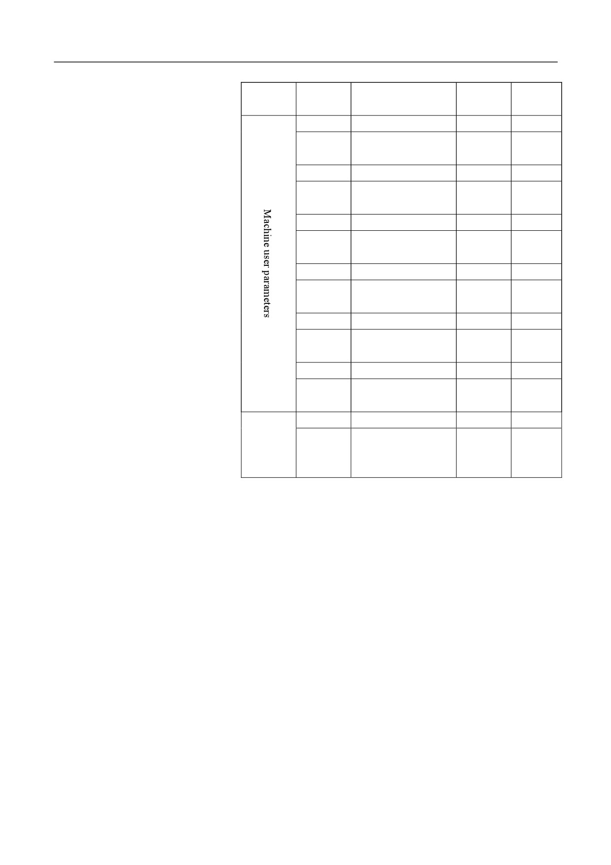
The table below describes the M parameter settings corresponding to the
subprograms. The user-defined parameters (010360-010373) correspond
to the subprograms (%1007-%1020) in USERDEF.CYC.
301
13. User Macro Program
Parameter
010366ter
M commandame
Para0 eter
Savetive
List
No.
corresponding to the
Value
Mode
010360
fixed cycled
G1013
13
Save
010367
M commandg to the
0
Save
corresponding to the
010361
fixed cycled
G1014
0
Save
010368
M commandg to the
0
Save
corresponding to the
010362
fixed cycled
G1015
0
Save
010369
M commandg to the
0
Save
corresponding to the
010363
fixed cycled
G1016
0
Save
010370
M commandg to the
0
Save
corresponding to the
010364
fixed cycled
G1017
0
Save
010371
M commandg to the
0
Save
corresponding to the
010365
fixed cycled
G1018
0
Save
010372
M commandg to the
0
Save
c
orresponding to the
fixed cycle G1019
010373
M command
0
Save
corresponding to the
fixed cycle G1020
Set the M command parameter (010360) corresponding to the fixed cycle
G1007 to 13, then you may use M13 to call the %1007 program in
USERDEF.CYC.
%1007; add user-defined subprogram 1007 to USERDEF.CYC
G0Z5
Z-50
G80
Example
M99
%1234; main program
G54
G1X0Y0Z0
M13; use M13 to call the 1007 subprogram
302
13. User Macro Program
X10Y10
X20Y30
Y0
X0
M30
Attention
1.
Currently,
the
fixed
cycle
cannot be used with
rotation/mirroring/scaling/G91 simultaneously.
2.
When using M commands to call subprograms, you need to add
G80 before M99 when the program ends.
13.4.5 Macro Program Cases
Case 1 (milling)
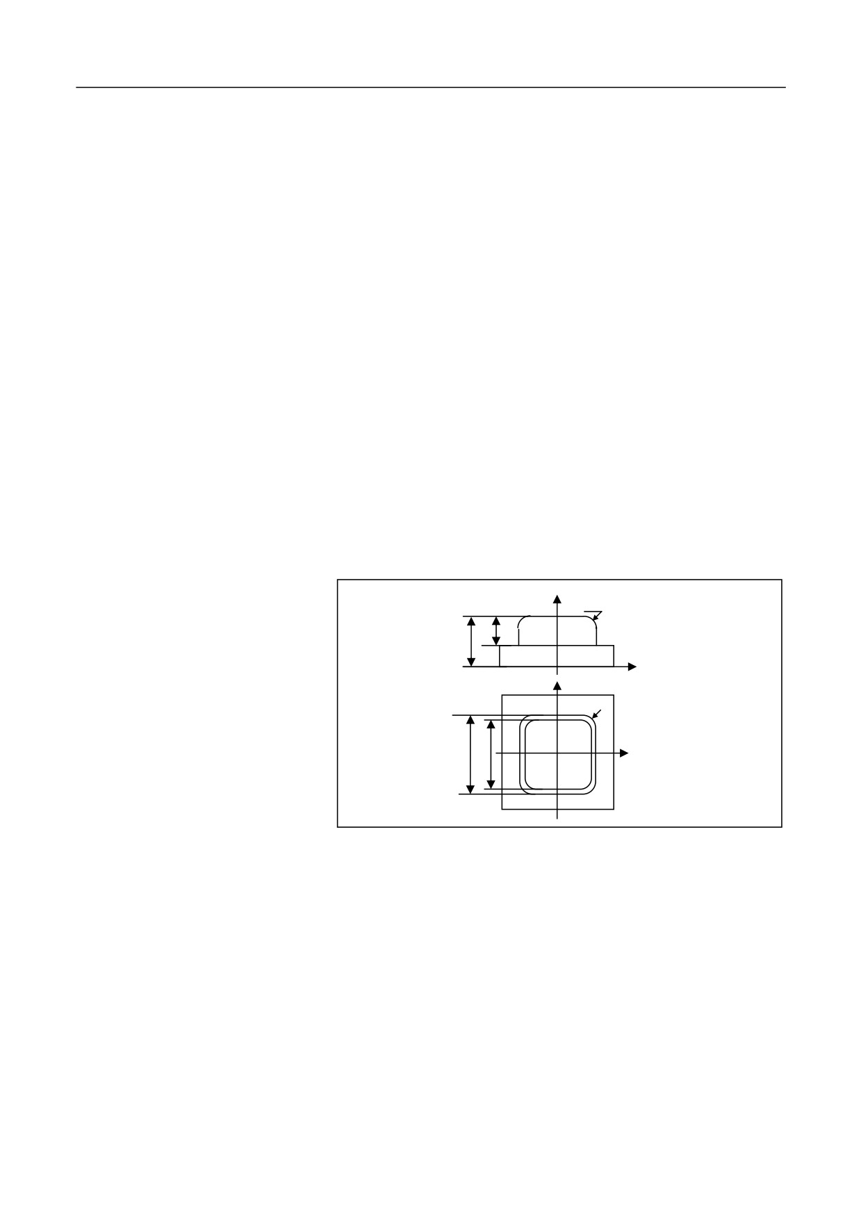
Use spher mill to machine the R5 fillet surface shown in the figure
below:
Z
R5
15
30
X
Y
R6
40 30
X
%0001 (The cutter location is the ball center)
G92 X-30 Y-30 Z25
#0=5 (Fillet radius)
#1=4 (Spher mill radius)
#2=180 (The initial value of the stepping angle Ȗ. Unit: degree)
WHILE #2 GT 90
G01 Z[25+[#0+#1]*SIN[#2*PI/180]] (Calculate Z axis height)
#101=ABS[[#0+#1]*COS[#2*PI/180]]-#0 (Calculate radius offset)
G01 G41 X-20 D01
Y14
G02 X-14 Y20 R6
303
13. User Macro Program
G01 X14
G02 X20 Y14 R6
G01 Y-14
G02 X14 Y-20 R6
G01 X-14
G02 X-20 Y-14 R6
G01 X-30
G40 Y-30
#2=#2-10
ENDW
M30
Case 1 (turning)
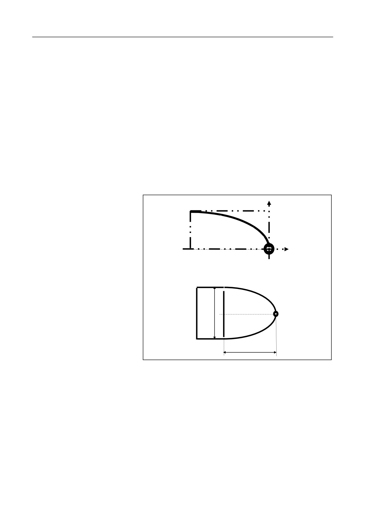
Use macro program to create a program for the parabola within interval
A[0, 8]. See the figure below:
A
8
B
32
Parabola B=-A2/2 within interval A [0, 8]
Ɏ16
32
%3401
N1 T0101
N2 G37
N3 #10=0; A coordinate
N4 M03 S600
N5 WHILE #10 LE 8
N6 #11=#10*#10/2
304
13. User Macro Program
N7 G90 G01 X[#10] Z[-#11] F500
N8 #10=#10+0.08
N9 ENDW
N10 G00 Z0 M05
N11 G00 X0
N12 M30
305
13. User Macro Program
13.4.6 Subprogram Classification
Internal subprogram
If the called program and the main program are in the same file, then the
called program is an internal subprogram.
Example
G code file name: O_test; %111: an internal subprogram, which is in the
same file with the main program %1001, and is called by G98 in the
main program.
%1001; main program
G92 X0 Y0 Z50
G91 G01 Z10 F400
M98 P111; call subprogram 111
G4X1
M30
%111; subprogram
G01x10y10z10
…
G80
M99
External subprogram
If the called program is in another file, it is an external subprogram.
The external subprogram file name must start with letter "O".
Example
G code file name: O_test; subprogram file name: O123
Main program
%1001
G92 X0 Y0 Z50
306