HNC-818. User Manual - page 8
12. Fixed Cycle
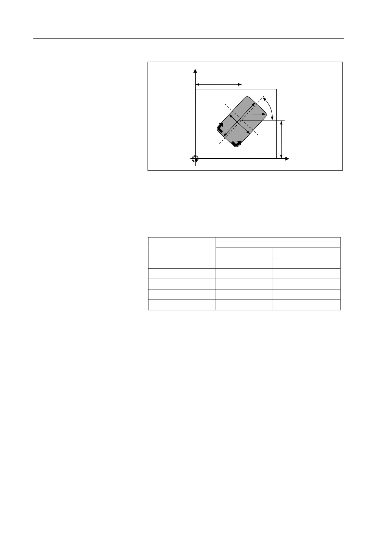
Parameter graph
Y
X
A
I
G
k
w
Y
G3
X
Milling direction
Before entering the cycle mode, you need to use the command to enable
spindle rotation. The system will calculate the reasonable milling
direction based on the spindle rotation direction (M03/M04) and the
command. See the table below:
Milling Direction
Execute M03/M04 before the cycle
(Parameter C)
M03 spindle CW
M04 spindle CCW
0: same direction
G03
G02
1: reversed direction
G02
G03
2: in G02 direction
G02
G02
3: in G03 direction
G03
G03
Left blank
G03
G03
1.
Select a random start point from which the tool may move to each
groove without any collision.
Operation Procedure
2.
Rough machining (D=1):
Go to the center of the long side of the groove with G00(reserve the
finishing allowance for the groove margin). The tool feeds
downward with the depth specified by Q, and then conducts milling
from the margin to the center for the upper part of the groove in the
milling direction specified by C. Then backing to the same start
position, the tool conducts milling from the groove surface to the
groove bottom (reserve the finishing allowance).
Finish machining (D=2):
Go to the center of the long side of the groove with G00
214
12. Fixed Cycle
(reserve the finishing allowance for the groove margin). The tool
feeds downward with the depth specified by H, and then conducts
milling from the center to the defined margin for the groove surface
in the milling direction specified by C. After that, the tool goes back
to the same point, moves to the surface for milling the finishing
allowance, from the surface to the bottom in the direction specified
by C.
3.
After machining, exit the tool to the initial plane or the reference
plane based on the current modal G98 or G99, and then the cycle
ends.
Attention
1.
This cycle requires milling tool with face tooth.
2.
The maximum feed depth for rough and finish machining is
specified by the parameter Q or H respectively. If the groove depth
is not divisible by Q or H, the final cut depth will be less than Q or
H.
3.
The values of N, K, W, I, E, O, Q and H should be non-negatives. If
the specified value is a negative value, the system will ignore the
negative symbol.
4.
For the information about alarms, see section 12.1.26.
5.
If the specified groove width is greater than the groove length, the
system will automatically exchange them and rotate to the expected
position.
6.
The parameter C specifies the milling direction, like G182.
7.
You need to use the command to enable spindle rotation before
entering the cycle mode.
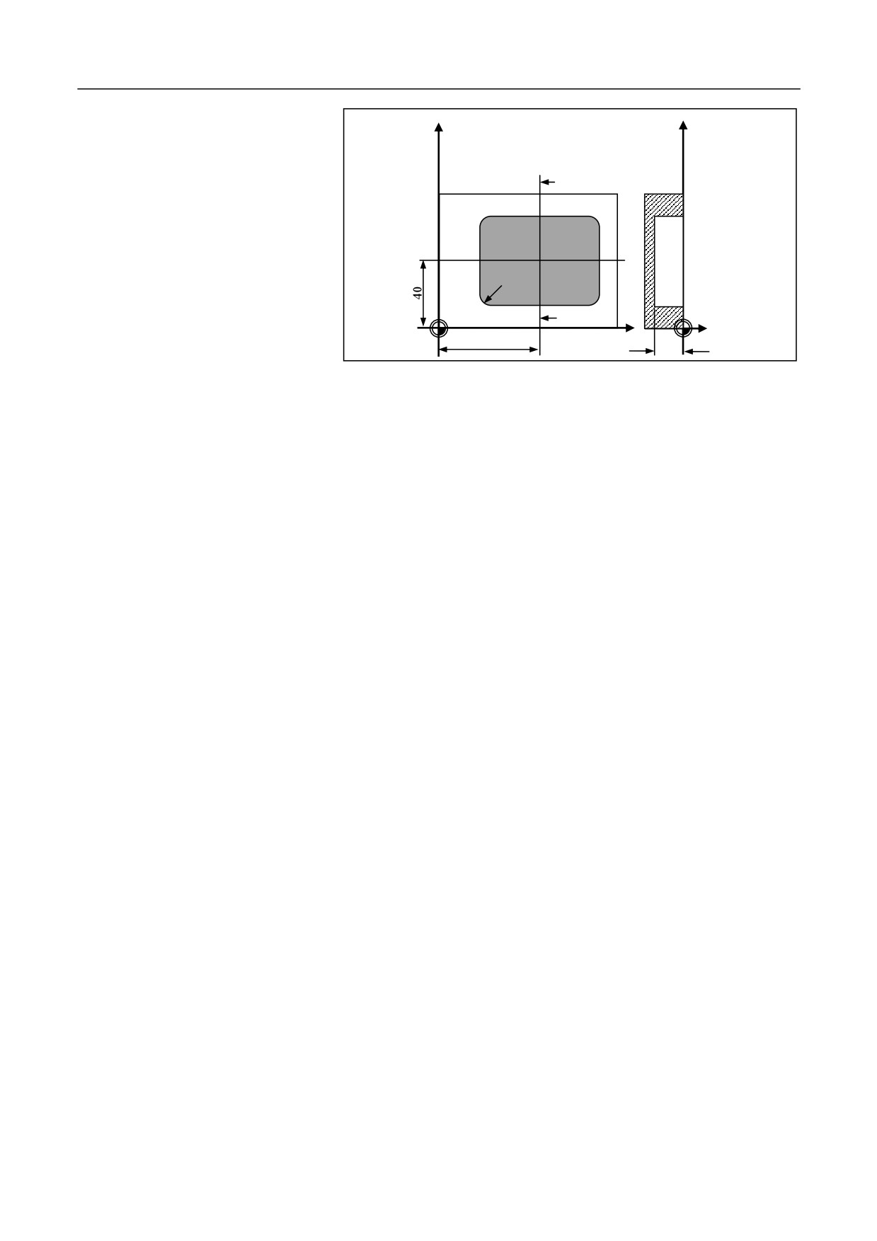
Conduct milling for the groove as shown in the figure below. Dimension
Example
of the groove:
Length: 60 mm; width: 40 mm; radius of the rounded arc: 8 mm; depth:
17.5 mm; angle between the groove and the X axis: 0 degree; finishing
allowance on the groove margin: 0.75 mm; finishing allowance on the
groove bottom: 0.2 mm; groove center: X60Y40; feed depth: 4 mm; tool
radius 5 mm
Only rough machining is required.
215
12. Fixed Cycle
Y
Y
A
A - B
R8
B
60
X
Z
17.5
%0526
N10 G54 G90 G17
N20 T20
N30 M06
N40 M04 S600
N50 G00 X60 Y40 Z5
N60 G98G184R5Z-17.5K60W40X60Y40I8F120Q4E0.75O0.2D1V5
N70 M30
216
12. Fixed Cycle
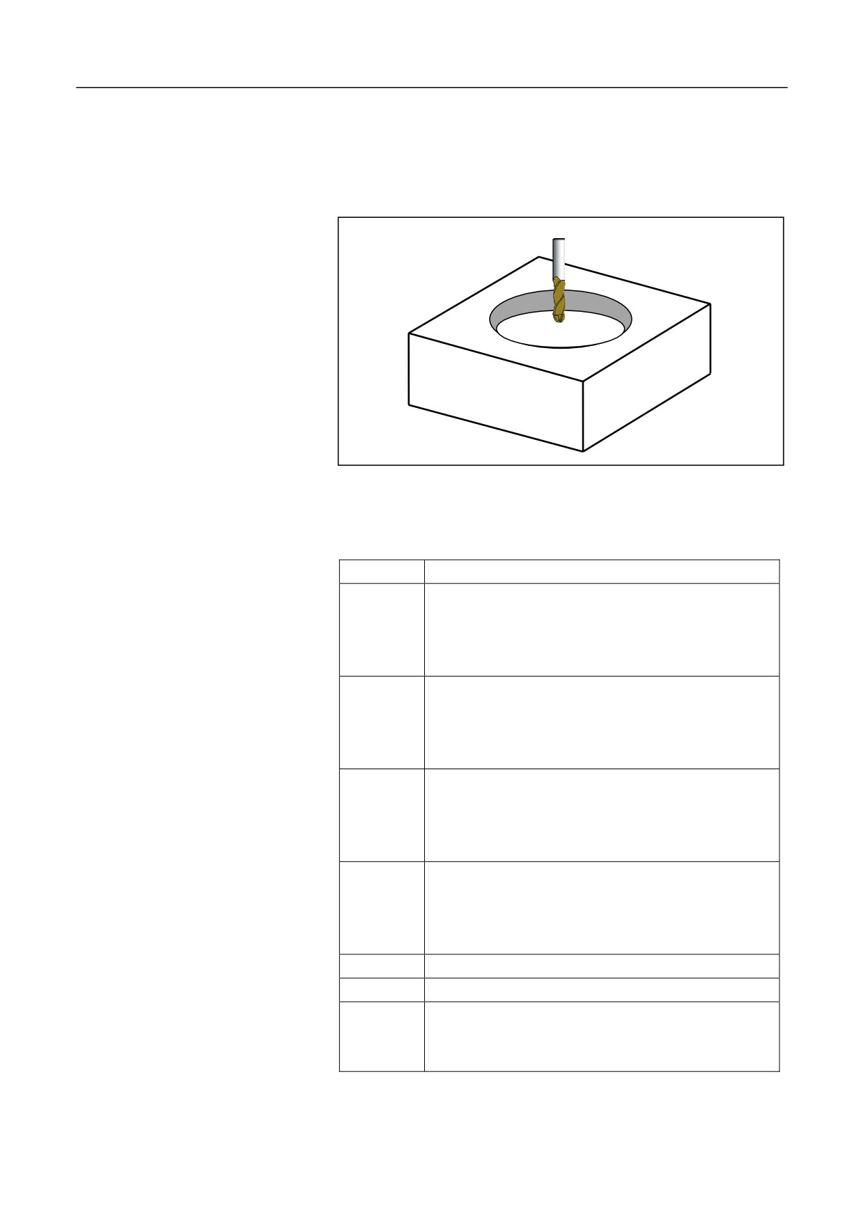
12.1.22 Circular Groove Cycle (G185)
Description
This cycle is used for rough or finish machining for circular grooves.
Format
(G98/G99)G185R_Z_X_Y_I_ F_ Q_E_O_H_U_P_C_D_V_
Parameter
Description
The coordinate value of the reference point R for
absolute programming, or the distance from reference
R
point R
to the initial plane for incremental
programming.
The coordinate value of the groove bottom for absolute
programming, or the incremental value from the
Z
groove bottom to the reference point R for incremental
programming.
The center of the groove. The first axis coordinate of
the current plane for absolute programming, and the
X
incremental value to the start point for incremental
programming.
The center of the groove. The second axis coordinate
of the current plane for absolute programming, and the
Y
incremental value to the start point for incremental
programming.
I
The radius of the circular groove.
F
Milling speed during rough machining.
The maximum feed depth for each time during rough
Q
machining
(It is optional when Q= groove depth-
finishing allowance of the groove bottom).
217
12. Fixed Cycle
The finishing allowance of the groove margin (It is optional
E
when E=0).
The finishing allowance of the groove bottom
(It is
O
optional when O=0 ).
The maximum feed rate for finish machining (It is optional
H
when H=Q).
The feed rate for finish machining (It is optional when
U
U=F ).
The spindle speed for finish machining (It is optional when
P
P= the spindle speed before cycle or the default spindle
speed).
The direction for milling each groove (It is optional when
C=3)
0:milling in the same direction with the spindle rotation;
C
1:milling in the reversed direction with the spindle
rotation; 2:milling in G02 direction; 3:milling in G03
direction
Machining type (It is optional when D=1 ).
D
1: rough machining; 2: finish machining
V
Tool radius.
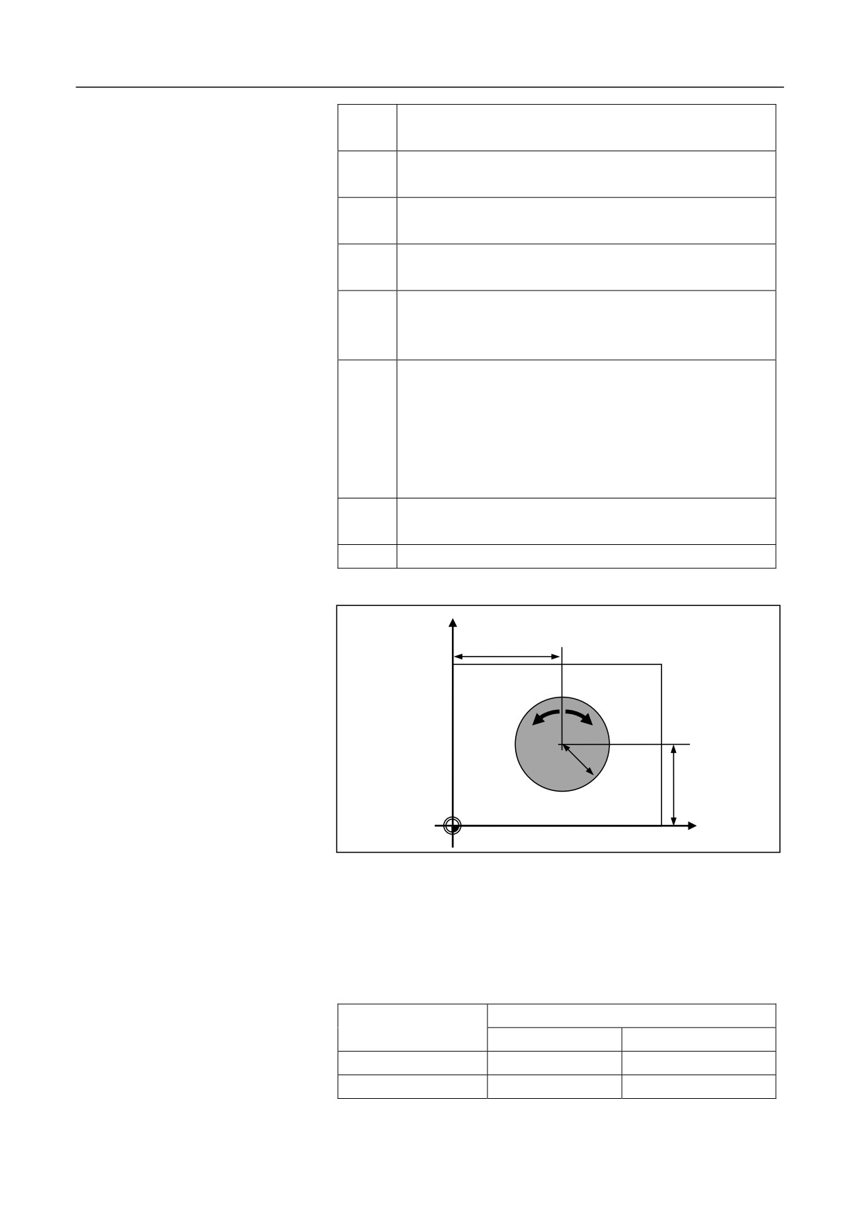
Parameter graph
Y
X
G3
G2
I
Y
X
Milling direction
Before entering the cycle mode, you need to use the command to enable
spindle rotation. The system will calculate the reasonable milling
direction based on the spindle rotation direction (M03/M04) and the
command. See the table below:
Milling Direction
Execute M03/M04 before the cycle
(Parameter C)
M03 spindle CW
M03 spindle CW
0: same direction
G03
G02
1: reversed direction
G02
G03
218
12. Fixed Cycle
2: in G02 direction
G02
G02
3: in G03 direction
G03
G03
Left blank
G03
G03
Operation procedure
1.
Select a random start point from which the tool may move to each
groove without any collision.
2.
Rough machining (D=1):
Go to the center of the long side of the groove with G00(reserve the
finishing allowance for the groove margin). The tool feeds
downward with the depth specified by Q, and then conducts milling
from the margin to the center for the upper part of the groove in the
milling direction specified by C. Then backing to the same start
position, the tool conducts milling from the groove surface to the
groove bottom (reserve the finishing allowance).
Finish machining (D=2):
Go to the center of the long side of the groove with G00. (reserve
the finishing allowance for the groove margin). The tool feeds
downward with the depth specified by H, and then conducts milling
from the center to the defined margin for the groove surface in the
milling direction specified by C. After that, the tool goes back to the
same point, moves to the surface for milling the finishing allowance,
from the surface to the bottom in the direction specified by C
3.
After machining, exit the tool to the initial plane or the reference
plane with the command G98 or G99, and then the cycle ends.
1.
For the information about alarms, see section 12.1.26.
2.
The maximum feed depth for rough and finish machining is
specified by the parameter Q or H respectively. If the groove depth
Attention
is not divisible by Q or H, the final cut depth will be less than Q or
H.
3.
The values of I, E, O, Q, and H should be non-negatives. If the
specified value is a negative value, the system will ignore the
negative symbol.
4.
The parameter C specifies the milling direction, like G182.
219
12. Fixed Cycle
Example
to enable spindle rotation before entering the cycle mode.
Conduct milling for the groove with the following specifications:
Circle center: X50 Y50; radius:
100 mm; depth: 50 mm; finishing
allowance on the groove bottom and margin:
2 mm and 1.5 mm
respectively; feed depth for rough machining: 4 mm; tool radius: 5 mm
G54 X0 Y0 Z40
G17 G90
T10
M06
M03 S650
G99 G185 R0 Z-50 X50 Y50 I100 F300 Q4 E1.5 O2 V5D1; rough
machining
X50 Y50 I100 P800 H1.5 D2; finish machining
M30
5.
You need to use the command
220
12. Fixed Cycle
12.1.23 Face Milling Cycle (G186)
Description
This cycle can be used to conduct milling for any rectangular end face.
The cycle for rough machining (perform multi-step reaming from surface
to finishing allowance) and finish machining (finish the end face) is
different.
Foramt
(G98/G99)G186R_Z_N_W_X_Y_ I_ A_F_Q_J_O_H_K_U_P_C_D_V_
Parameter
Description
The coordinate value of the reference point R for
absolute programming, or the distance from reference
R
point R to the initial plane for incremental
programming.
The coordinate value of the groove bottom for absolute
programming, or the incremental value from the
Z
groove bottom to the reference point R for incremental
programming.
N
The first axis length of the workpiece.
W
The second axis length of the workpiece.
The start position.
The first axis coordinate of the current plane for
X, Y
absolute programming, or the incremental value to the
current point during incremental programming.
The safety margin in the milling direction (It is
I
optional when I= tool radius).
The angle formed by the long side of the end face and
A
the first positive axis (It is optional when A=0 ).
F
Milling speed during rough machining.
The maximum feed depth for each time during rough
Q
machining (It is optional when Q= groove depth-
finishing allowance of the groove bottom).
The milling width during rough machining (It is
J
optional when J= tool radius x 80%).
The finishing allowance of the workpiece bottom (It is
O
optional when O=0).
The maximum feed depth during finish machining (It
H
is optional when H=Q).
The cutting width during rough machining (It is
K
optional when K= tool radius x 80%).
221
12. Fixed Cycle
The milling speed for finish machining (It is optional when
U
U=F).
The spindle speed for finish machining (It is optional when
P
P= the spindle speed before cycle or the default spindle
speed).
The direction for milling each groove (It is optional when
C=3)
0:milling in the same direction with the spindle rotation;
C
1:milling in the reversed direction with the spindle
rotation; 2:milling in G02 direction; 3:milling in G03
direction
Machining type (It is optional and D=1 by default)
D
y
1: rough machining
y
2: finish machining
V
The tool radius.
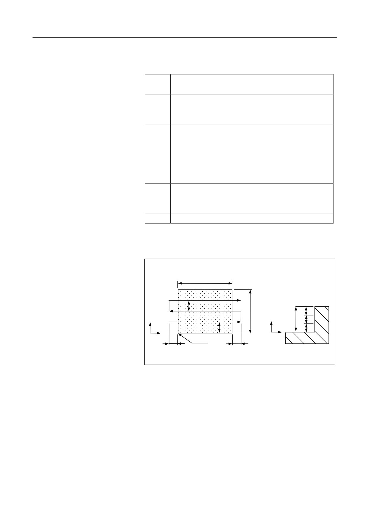
• C=0, D=1, bidirectional machining along the X axis
Basic description
N
J
W
Q
+Y
+Z
Z-O Q
J
Q
+X
+Y
I
(X,
I
222
12. Fixed Cycle
•
•
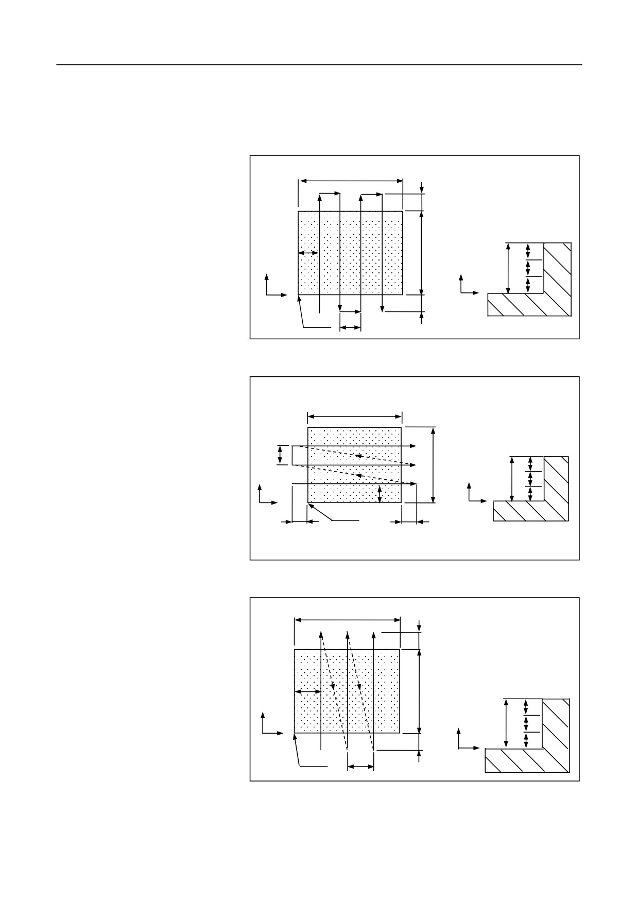
• C=1, D=1, bidirectional machining along the Y axis
N
J
J
I
J
W
Q
+Y
+Z Z-O Q
Q
+X
I
+X
(X, Y)
J
• C=2, D=1, unidirectional machining along the X axis
N
J
W
Q
+Y
+Z
Z-O Q
J
Q
+Y
+X
I
(X, Y)
I
• C=3, D=1, unidirectional machining along the Y axis
N
I
J
W
+Y
Q
+Z
Z-O Q
Q
+X
I
(X, Y)
J
+Y
Note: The figures above show the milling cycle (rough machining) only
for the end face of the G17 plane. The cycle for G18/G19 is similar, and
223
12. Fixed Cycle
that for the finish and comprehensive
machining (D=2) is also similar.
1.
The values of N, W, I, O, Q, J, H and K should be non-negatives. If
the specified value is a negative value, the system will ignore the
negative symbol.
Attention
2.
For the feed width (specified by J/K) or the feed depth (specified by
Q/H), the final cut will be less than the feed width or the feed depth
if the feed rate is not divisible by them.
3.
Before executing the cycle, use the command to enable the spindle
rotation.
4.
For the information about alarms, see section 12.1.26.
Example
end face, with the following end dimension and relative parameters:
Start plane: 10 mm; reference plane: 2 mm, only rough machining, each
milling width: 10 mm; each feed depth: 6 mm; total milling depth: 11
mm; milling start point (100, 100); end face dimension: 60 mm x 40 mm;
safety margin in the milling direction: 5 mm; bidirectional milling along
the X axis; feed rate on the surface: 500 mm/min; tool radius: 5 mm.
%1018
N10
G54 X0 Y0 Z20
N20
G17 G90
N30
T10
N40
M06
N50
M03 S650
N60
G00 X0 Y0 Z20
N70
G99G186 Z-11 R0 N60 W40 X100 Y100 I5 F500 Q6 J10 V5
N80
M30
Conduct milling for a rectangular
224
12. Fixed Cycle
12.1.24 Rectangular Boss Cycle (G188)
Description
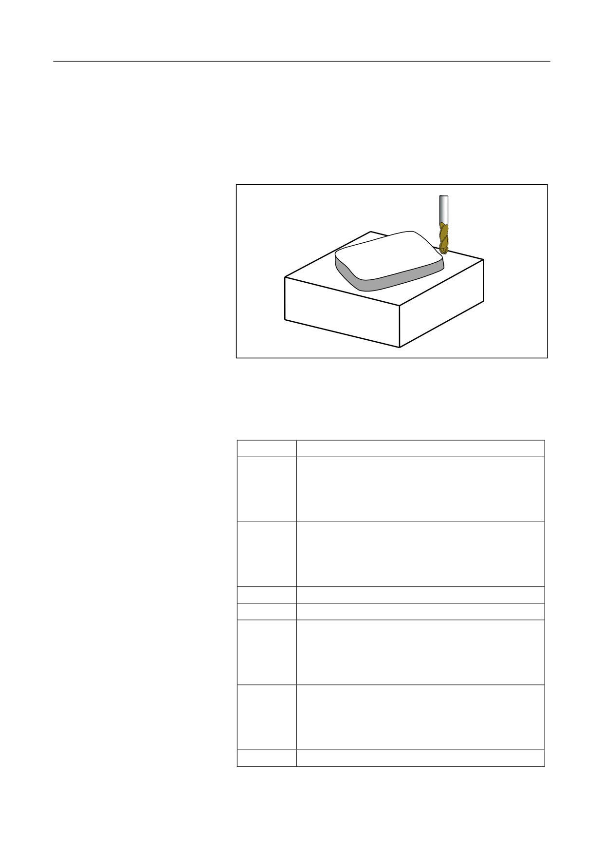
This cycle is used to conduct machining for rectangular boss of arbitrary
size on a plane. The rectangular boss may have rounded corners. You
may select roughing, finishing or comprehensive machining as required.
Format
(G98/G99)G188R_Z_N_W_X_Y_J_K_I_ A_F_ Q_E_O_H_U_P_C_D_V_
Parameter
Description
The coordinate value of the reference point R for
absolute programming, or the distance from reference
R
point R to the initial plane for incremental
programming.
The coordinate value of the boss bottom for absolute
programming, or the incremental value from the boss
Z
bottom to the reference point R for incremental
programming.
N
The length of the rectangular boss.
W
The width of the rectangular boss.
The center of the rectangular boss. The first axis
coordinate of the current plane for absolute
X
programming, and the incremental value to the start
point for incremental programming.
The center of the rectangular boss. The second axis
coordinate of the current plane for absolute
Y
programming, and the incremental value to the start
point for incremental programming.
J
The length of the rough rectangular boss.
225
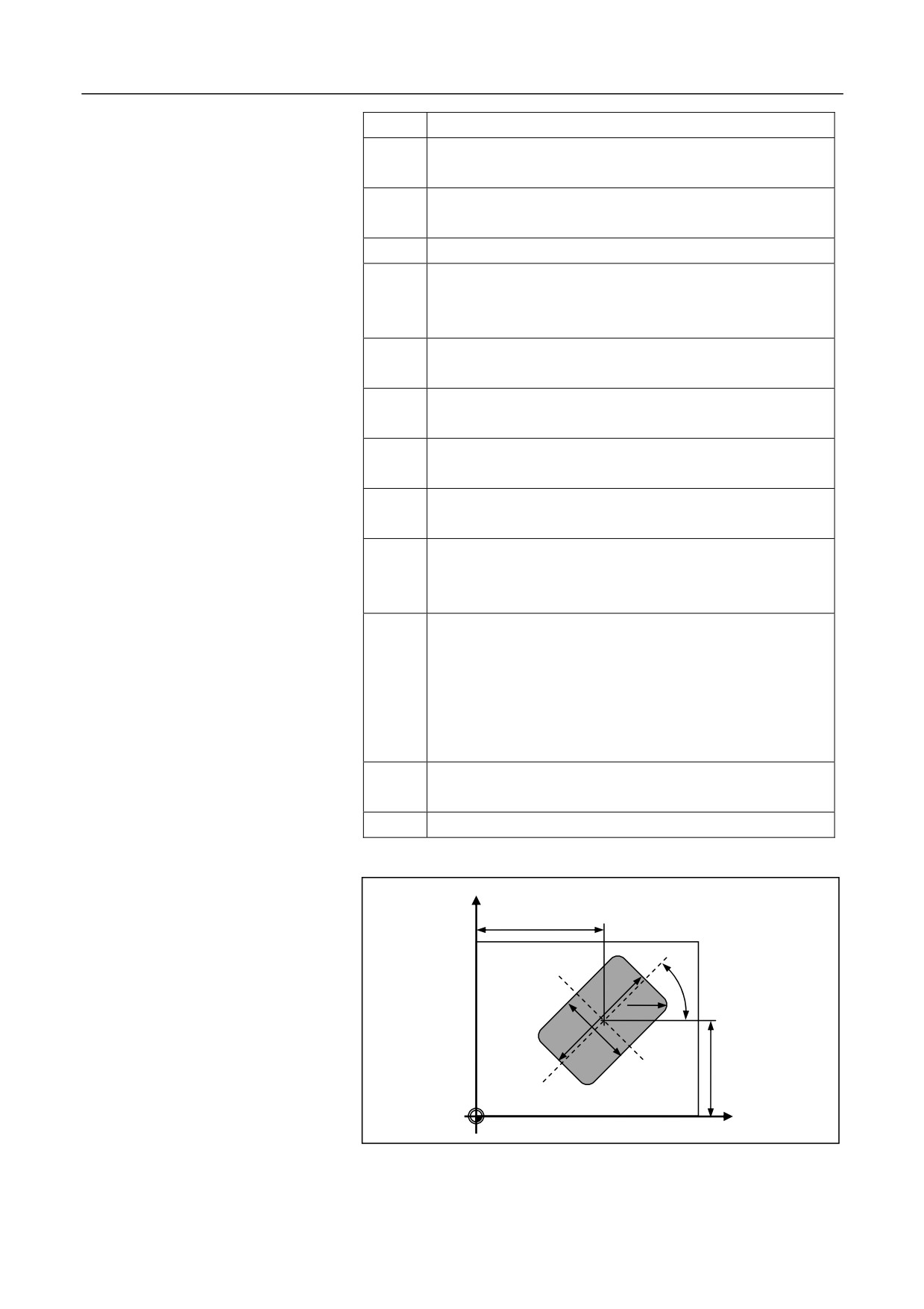
12. Fixed Cycle
K
The width of the rough rectangular boss.
The radius of the rounded corner in the rectangular boss (It
I
is optional when I=W/2 ).
The angle formed by the long side of the rectangular boss
A
and the first positive axis (It is optional when A=0).
F
The milling speed for rough machining.
The maximum feed depth for each rough machining (It is
Q
optional when Q = groove depth - finishing allowance at
the groove bottom).
The finishing allowance at the boss margin (It is optional
E
when E=0).
The finishing allowance at the boss bottom (It is optional
O
when O=0).
The maximum feed depth for finish machining (It is
H
optional when H=Q).
The feed speed for finish machining (It is optional when
U
U=F).
The spindle speed for finish machining (It is optional when
P
P= the spindle speed before cycle or the default spindle
speed).
The milling direction for the boss (It is optional when
C=3 ).
0:milling in the same direction with the spindle rotation;
C
1:milling in the reversed direction with the spindle
rotation; 2:milling in G02 direction; 3:milling in G03
direction
Machining type (It is optional and D=1 by default).
D
1: rough machining; 2: finish machining
V
Tool radius.
Parameter graph
Y
X
A
I
N
W
Y
X
226
12. Fixed Cycle
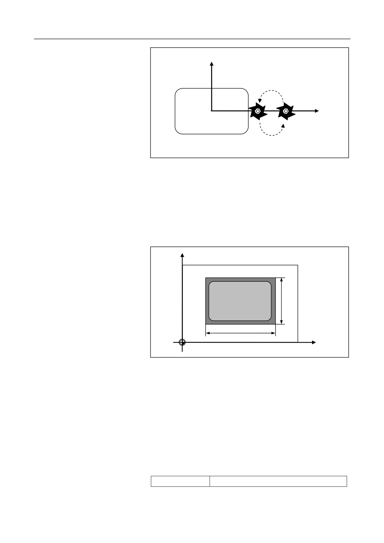
Y
Path for entering
Semicircle path for entering and
existing
X
Path for existing
To ensure the tool smoothly moves into the workpiece, the cycle
automatically adds a semicircle path when entering and exiting the
workpiece. The semicircle radius is determined by the cycle parameters,
and the semicircle direction is opposite to the milling direction. For
example, if the milling direction is specified by G2, then the added
semicircle is in the direction of G3.
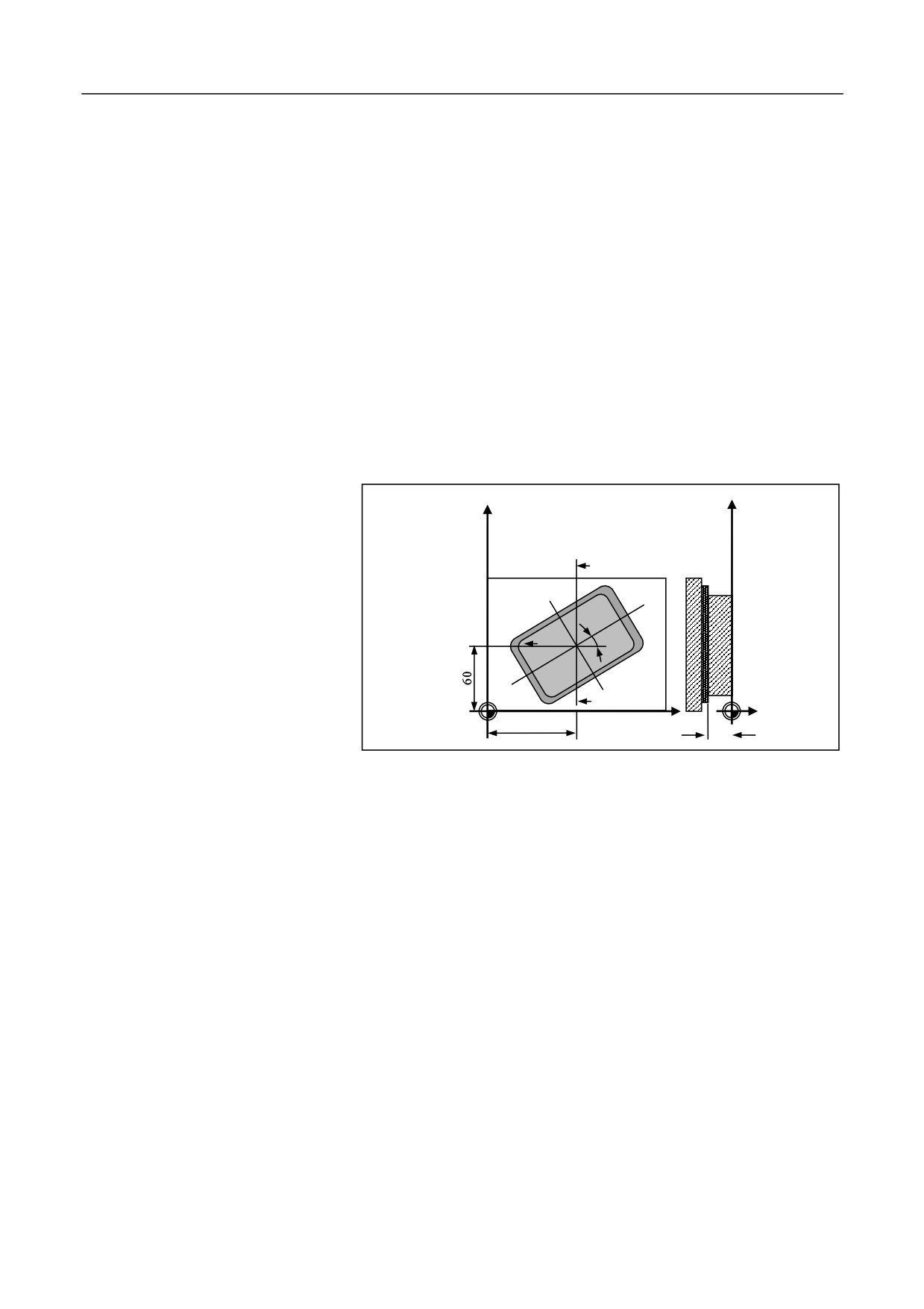
Dimension of rough boss
Y
K
J
X
For the machining of workpiece with prior casting, the rough size of
rectangular boss, which is symmetrical to the size of the boss with the
center(X,Y), may be taken into account.
Milling direction
Before entering the cycle mode, you need to use the command to enable
spindle rotation. The system will calculate the reasonable milling
direction based on the spindle rotation direction (M03/M04) and the
commands. See the table below:
Milling Direction
Execute M03/M04 before the cycle
227

12. Fixed Cycle
(Parameter C)
M03 spindle CW
M03 spindle CW
0: same direction
G03
G02
1: reversed direction
G02
G03
2: in G02 direction
G02
G02
3: in G03 direction
G03
G03
Left blank
G03
G03
Operation procedure
1.
Selecting a start point, which must be to the right of the boss in the
first postive axis direction of the plane. You need to consider the
automatically added semicircle during the cycle.
2.
Rough machining (D=1):
Go to the reference plane over the long side of the boss with G00, feed
downward with the specified depth, and then in the milling direction,
enter the workpiece contour through a semicircle path to conduct milling
from the surface to the finishing allowance of the margin, and exit the
workpiece contour through a semicircle path in the opposite direction.
Use G00 to rapidly move to the start point, and then conduct milling
from the groove surface to the finishing allowance of the bottom.
Finish machining (D=2):
Go to the reference plane over the long side of the boss with G00, feed
downward with the specified depth, and then in the milling direction,
enter the workpiece contour through a semicircle path to machine the
finishing allowance of margin. After that, exit the workpiece contour
through a semicircle path in the opposite direction. Use G00 to rapidly
move to the start point, feed downward again to machine the finishing
allowance of the bottom.
3.
After completing the machining, exit the tool to the initial point or
the reference point based on the current modal G98 or G99, and
then the cycle ends.
Attention
1.
For the information about alarms, see section 12.1.26.
2.
The values of W, J, K, I, O, Q and H should be non-negatives. If the
specified value is a negative value, the system will ignore the
negative symbol.
228
12. Fixed Cycle
3.
For the maximum feed depth
for rough and finish machining
(specified by Q and H
respectively), if the feed rate is
not divisible , the final cut will
4.
Before executing the cycle, use the command to enable the spindle
be less than Q or H.
rotation.
5.
If the specified width is greater than the length, the system will
automatically exchange them and rotate to the expected position.
Example
Conduct milling for the boss as shown in the figure below:
Dimension: 60 mm x 40 mm; rough dimension: 80 mm x 50 mm; tool
radius: 3 mm
Y
Y
A
A - B
R1
10°
B
80
X
Z
17.5
%1019
G17 G54 G90
T10
M06
M03 S650
G98 G188 R2Z-17.5N60W40X80Y60J80K50I15A10F200Q11E2O1V3
M30
229
12. Fixed Cycle
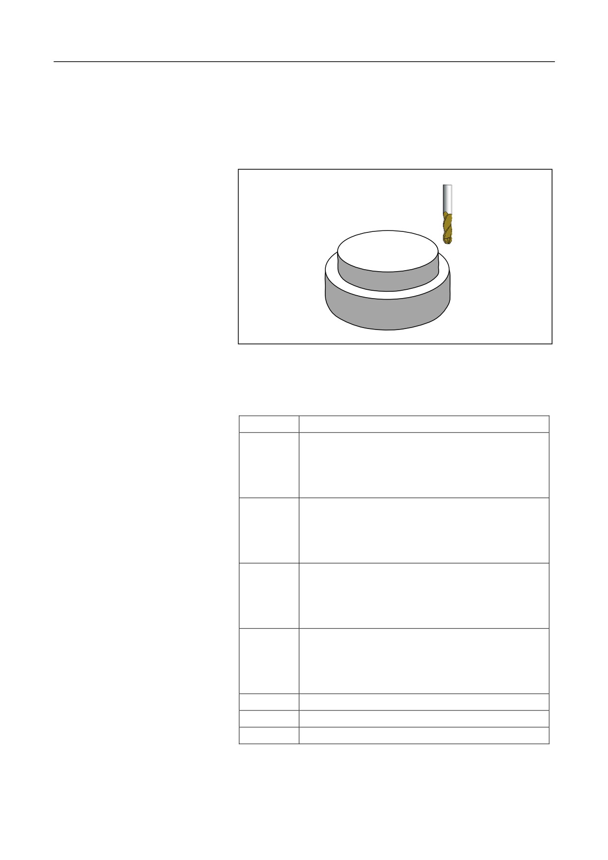
12.1.25 Circular Boss Cycle (G189)
Description
The cycle is used to conduct machining for circular boss with arbitrary
size.
Format
(G98/G99)G189R_Z_X_Y_ I_ J_F_ Q_E_O_H_U_P_C_D_V_
Parameter
Description
The coordinate value of the reference point R for
absolute programming, or the distance from reference
R
point R to the initial plane for incremental
programming.
The coordinate value of the boss bottom for absolute
programming, or the incremental value from the boss
Z
bottom to the reference point R for incremental
programming.
The center of the rectangular boss. The first axis
coordinate of the current plane for absolute
X
programming, and the incremental value to the start
point for incremental programming.
The center of the rectangular boss. The second axis
coordinate of the current plane for absolute
Y
programming, and the incremental value to the start
point for incremental programming.
I
The radius of the circular boss.
J
The radius of the rough circular boss.
F
The milling speed for rough machining.
230
12. Fixed Cycle
The maximum feed depth for each rough machining (It is
Q
optional when Q = groove depth - finishing allowance at
the groove bottom).
The finishing allowance at the boss margin (It is optional
E
when E=0).
The finishing allowance of the boss bottom (It is optional
O
when O=0 ).
The maximum feed depth for finish machining
(It is
H
optional when H=Q).
The feed speed for finish machining (It is optional when
U
U=F ).
The spindle speed for finish machining (It is optional when
P
P= the spindle speed before cycle or the default spindle
speed).
The milling direction for the grooves (It is optional when
C=3 ).
0:milling in the same direction with the spindle rotation;
C
1:milling in the reversed direction with the spindle
rotation; 2:milling in G02 direction; 3:milling in G03
direction
Machining type (It is optional when D=1)
D
1: rough machining; 2: finish machining
V
Tool radius.
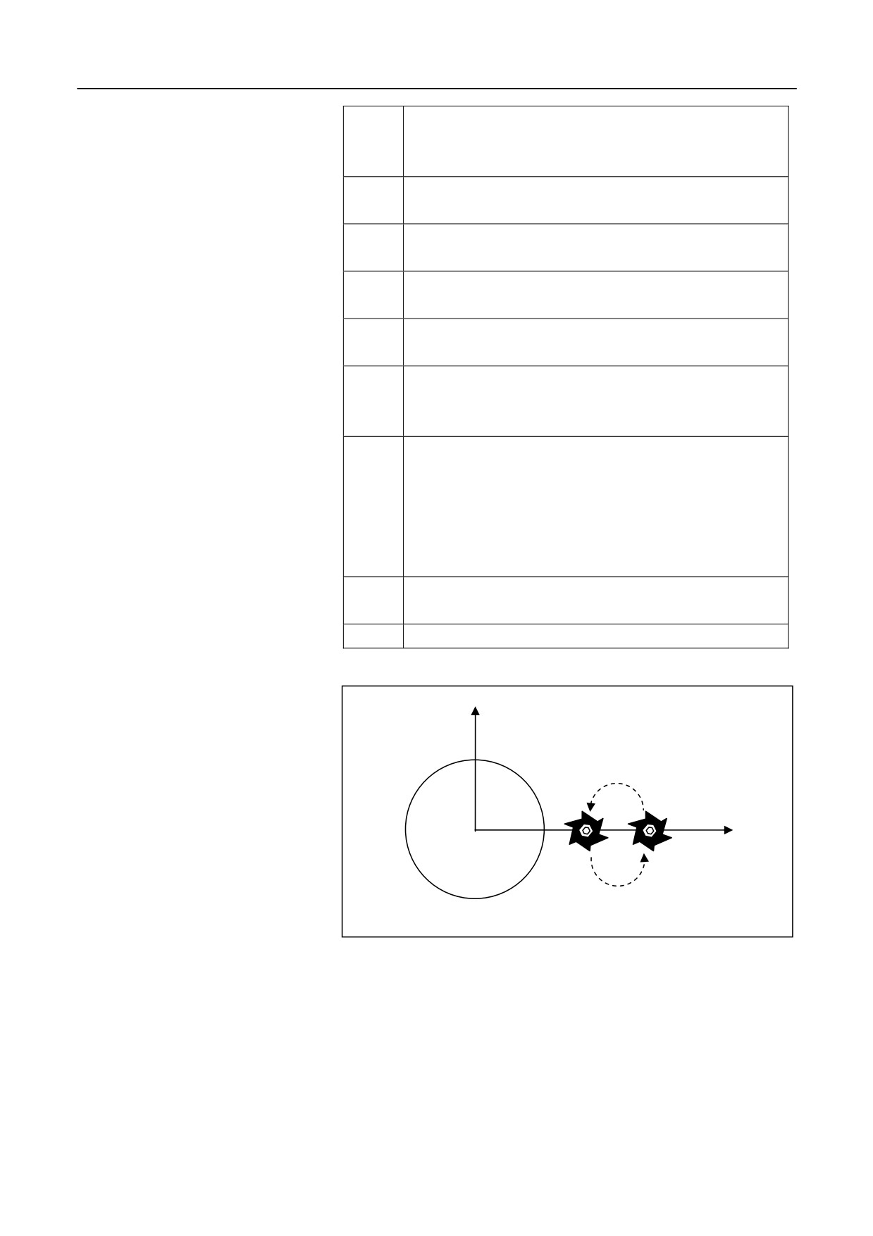
Semicircle path for entering and
Y
existing
Return to the running contour
X
Exit the running contour
Similar as G188, to ensure the tool smoothly moves into the workpiece,
the cycle automatically adds a semicircle path when entering and exiting
the workpiece. The semicircle radius is automatically determined by the
cycle. The direction of the semicircle is opposite to that of milling.
231

12. Fixed Cycle
Dimension of rough boss
Similar as G188, you may set the dimension of the rough boss, with the
center (X, Y).
Milling direction
Before entering the cycle mode, you need to use the command to enable
spindle rotation. The system will calculate the reasonable milling
direction based on the spindle rotation direction (M03/M04) and the
commands. See the table below:
Milling Direction
Execute M03/M04 before the cycle
(Parameter C)
M03 spindle CW
M04 Spindle CCW
0: same direction
G03
G02
1: reversed direction
G02
G03
2: in G02 direction
G02
G02
3: in G03 direction
G03
G03
Left blank
G03
G03
1.
Select a start point, which must be to the right of the boss in the first
Operation procedure
postive axis direction of the plane. You need to consider the
automatically added semicircle during the cycle.
2.
Rough machining (D=1):
Go to the reference plane over the long side of the boss with G00, feed
downward with the specified depth, and then in the milling direction,
enter the workpiece contour through a semicircle path to conduct milling
from the surface to the finishing allowance of the margin, and exit the
workpiece contour through a semicircle path in the opposite direction.
Use G00 to rapidly move to the start point, and then conduct milling
from the groove surface to the finishing allowance of the bottom.
Finish machining (D=2):
Go to the reference plane over the long side of the boss with G00, feed
downward with the specified depth, and then in the milling direction,
enter the workpiece contour through a semicircle path to machine the
finishing allowance of margin. After that, exit the workpiece contour
through a semicircle path in the opposite direction. Use G00 to rapidly
move to the start point, feed downward again to machine the finishing
allowance of the bottom.
232
12. Fixed Cycle
3.
After completing the machining, exits the tool to the initial point or
the reference point based on the current modal G98 or G99, and
then the cycle ends.
1.
For the information about alarms, see section 12.1.26.
Attention
2.
The values of J, K, I, E, O, Q and H should be non-negatives. If the
specified value is a negative value, the system will ignore the
negative symbol.
3.
For the maximum feed depth for rough and finish machining
(specified by Q and H respectively), if the feed rate is not divisible
by them, the final cut will be less than Q or H.
4.
Before executing the cycle, use the command to enable the spindle
rotation.
5.
If the specified width is greater than the length, the system will
automatically exchange them and rotate to the expected position.
Example
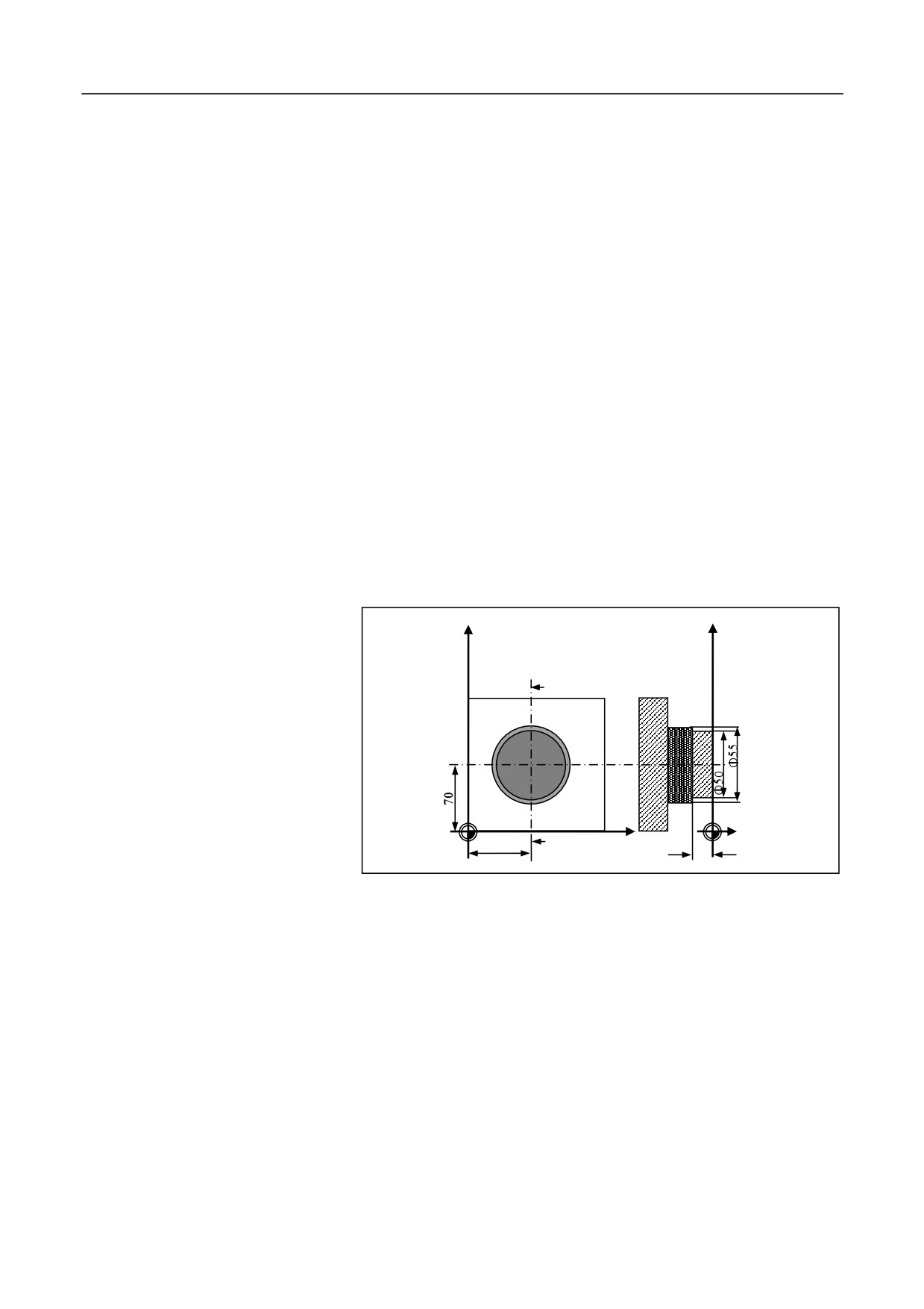
Conduct milling for the boss as shown in the figure below:
Rough boss radius: 55 mm; each feed depth: 10 mm; tool radius: 5 mm
Y
Y
A
A - B
60
B
X
Z
20
%1020
G17 G54 G90
T10
M06
M03 S650
G98G189 R2Z-20X60Y70I25J27.5F200Q10E1O1V5
M30
233

12. Fixed Cycle
12.1.26 Alarm Information for Milling Cycle
During fixed cycle, if the system detects an error, an alarm will be
reported, and the current cycle execution will be stopped. After you
modify the program, the system will proceed to run the ongoing cycle.
This section describes the alarms that may be reported during the milling
cycle, and provides alarm analysis and suggestions, based on which you
may modify the program.
Alarm
Alarm Text
Source
Reasons and Suggestions
No.
G181
G182
"MILLING
G183
CYCLE: TOOL
G184
The tool radius V is not specified
800
OFFSET
G185
before executing the cycle.
NUMBER NOT
G186
DEFINED."
G188
G189
G181
This alarm is reported if R is not
G182
specified in the program and the cycle
"MILLING
G183
cannot detect the modal R value. This
CYCLE:
G184
parameter should be specified as it is
801
REFERENCE
G185
required when the groove depth is
PLANE NOT
G186
defined in the incremental value or the
DEFINED."
G188
tool exits to the R plane after the cycle
G189
is completed.
G181
"MILLING
G182
CYCLE:
G183
The groove bottom position must be
POSITION OF
G184
802
specified; otherwise, the groove depth
BOTTOM OF
G185
cannot be defined.
GROOVE NOT
G186
DEFINED."
G188
G189
"MILLING
This alarm is reported when the
CYCLE:
G181
groove number is set to 0. The number
803
NUMBER OF
G182
of grooves should be an integer
GROOVE IS
G183
greater than 0.
SET TO ZERO."
234

12. Fixed Cycle
"MILLING
CYCLE: GROOVE
For the groove with user-defined width,
804
LENGTH
G182
the length should be greater than the
DEFINED
TOO
width; otherwise, this alarm is reported.
SMALL."
G181
G182
G183
This alarm is reported when the tool
"M-CYC: TOOL
G184
radius is greater than the defined groove
805
RADIUS
TOO
G185
length. You may select a milling tool with
MUCH."
G186
relative smaller radius for the milling.
G188
G189
"MILLING
This alarm is reported if the arc center is
CYCLE: CENTER
G181
not specified in the program and no
806
POSITION
OF
G182
related modal position is detected by the
ARC MADE OF
G183
cycle.
GROOVES."
"M-CYC:
AR
G181
If there is no modal arc radius value, the
807
MADE OF GV
G182
radius should be specified in this line;
NOT DEFINED."
G183
otherwise, this alarm is reported.
Because of the angle formed by the tool
radius and the groove, there may be
"M-CYC:
G181
interference
among the machined
INTERFER
808
G182
grooves, which may affect the groove
BTWN
G183
contour shape. The system conducts the
GROOVE"
interference detection before the cycle
and provides prompts for you.
This alarm is reported when the groove
"M-CYC:
GV
G181
number or the angle between grooves is
809
NO.&DEF OF AI
G182
defined improperly, e.g. groove number x
CONFLICTS"
G183
the angle between grooves > 360 degrees.
G181
G182
G183
This alarm is reported when the
"The maximum feed
G184
maximum feed depth for each time (Q) is
810
depth for each time
G185
greater than the groove depth. You may
is over large."
G186
decrease the value of Q.
G188
G189
235

12. Fixed Cycle
G181
G182
G183
This alarm is reported when the spindle
"M-CYC:
G184
does not rotate before the cycle. The
811
ROTATE SPDL
G185
spindle status is detected before the
BEF CYC RUN."
G186
cycle is executed.
G188
G189
G184
"CG OR BOSS
This alarm is reported when the center
G185
812
CP
NOT
of the circular groove or boss is not
G188
DEFINED."
specified.
G189
"M-CYC: CG OR
This alarm is reported when the radius
G185
813
BOSS R NOT
of the circular groove or boss is not
G189
DEFINED."
specified.
G182
"M-CYC:
G183
The reserved finishing allowance for
F.ALOW
OF
G184
814
the margin is too large to complete. You
MARGIN
G185
may decrease the finishing allowance.
MUCH."
G188
G189
G182
G183
"M-CYC:
G184
The reserved finishing allowance for
F.ALOW
OF
815
G185
the bottom is too large to complete. You
BOTTOM
G186
may decrease the finishing allowance.
MUCH."
G188
G189
G182
G183
For finish machining, this alarm is
"M-CYC: MAX
G184
reported if the maximum feed depth for
816
F.DEP
OF
G185
each time (H) is greater than the groove
FINISH MUCH."
G186
depth. You may decrease the value of
G188
H.
G189
236

12. Fixed Cycle
G182
G183
This alarm is reported if the defined
"M-CYC: DIR
G184
milling direction is not supported by
817
MILLING
G185
the system, that is the value specified
ERROR."
G186
for C is not within the allowed range
G188
(0, 1, 2, 3).
G189
G182
G183
This alarm is reported if a milling
"M-CYC: DEF
G184
type not supported by the system is
818
OF MACHING
G185
defined, that is the value specified for
TYPE ERROR."
G186
D is not within the allowed range (1,
G188
2).
G189
For G186, the dimension of the end
face should be specified for the
"M-CYC: W.SIZE
819
G186
workpiece to be machined, e.g.
NOT DEFINED."
length and width; otherwise, this
alarm is reported.
For G186, the start point for the
"M-CYC: ST PT
milling should be specified, generally
820
OF MIL NOT
G186
the lower left corner of the workpiece
DEFINED."
on the machining plane; otherwise,
this alarm is reported.
For G186, the safety margin should
"M-CYC:
be specified for a good milling effect.
821
SAFETY LMT
G186
Its value cannot be lower than the
TOO SMALL."
radius of the milling tool.
"M-CYC: WID
For G186, the milling width for
822
OF RM TOO
G186
rough machining cannot be greater
MUCH."
than the tool diameter.
"M-CYC: WID
For G186, the milling width for finish
823
OF RM TOO
G186
machining cannot be greater than the
MUCH."
tool diameter.
"M-CYC:
WP
For G189 and G188, the workpiece
G188
824
SIZE ON BOSS
dimension should be defined;
G189
NOT DEF."
otherwise, this alarm is reported.
237

12. Fixed Cycle
G181
This alarm is reported if the
"M-CYC:
G182
groove length or width is not
GV/BOSS
826
G183
specified in this line or the related
LEN/WID
G184
modal value of the groove length
NOT DEF."
G188
cannot be detected.
"M-CYC:
For
184 or
188, the rounded
CR
OF
corner can be defined, but the arc
G184
829
REC.GV/B
radius cannot be greater than long
G188
OSS
side / 2; otherwise, this alarm is
MUCH."
reported.
"M-CYC:
For G189 and G188, the rough
WP SIZE
G188
boss dimension should be greater
830
ON
G189
than the contour dimension;
BOSS<MA
otherwise, this alarm is reported.
C SIZE."
G181
The parameter V indicates the
G182
compensation number in the tool
"M-CYC:
G183
compensation table. The value
TOOL RAD
G184
873
entered in the compensation
CANNOT
G185
number is the tool radius. This
BE 0."
G186
value cannot be zero; otherwise,
G188
this alarm is reported.
G189
"The
G182
This alarm is reported when the
finishing
G183
finishing allowances of groove
allowances
G184
wall and groove bottom are not
874
is
not
G185
defined simultaneously or both
defined for
G186
are specified as
0 during finish
the
G188
machining.
finishing."
G189
238

12. Fixed Cycle
12.2 Simple Cycle for Turning Machines (T)
For turning machines, there are five simple cycles. See the table below:
G Code
Functions
G80
Inner (outer) diameter cutting cycle
G81
End-face cutting cycle
G82
Thread cutting cycle
G74
End-face deep-hole drilling cycle
G75
Outer diameter grooving cycle
The cycle is to use a G code program block to complete the machining of
multiple blocks, to simplify the programs.
Attention
1.
The cycle described in this section can only be used for turning
machines.
2.
The commands G83, G87, G84and G88 have no positioning
function. To conduct positioning, you need to execute G01 or G00
outside the fixed cycle.
239
12. Fixed Cycle
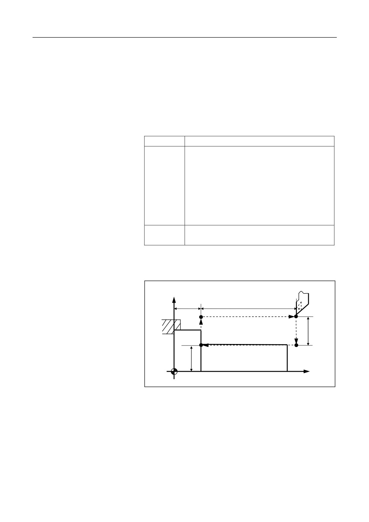
12.2.1 Inner (Outer) Diameter Cutting Cycle (G80)
This cycle can be used for inner (outer) diameter cutting of cylindrical
and conical surfaces.
Cylindrical surface cutting
G80 X_/U_ Z_/W_ F_
Parameter
Description
X/U Z/W
The cutting end point C at the workpiece coordinate
system for absolute value programming;
The relative distance from the cutting end point C to
the cycle start point A for the incremental value
programming.
Use U and W to express them in the blueprint and the
direction of path 1 and 2 determine whether it is a
positive or a negative value.
F
Feed speed (indicates to move at the speed specified
by F) (mm/min)
The tool moves along the path AĺBĺCĺDĺA. See the figure below:
+X
z
w
Tool exit point
Cycle start point
D
4R
A
3F
1R
u/2
2F
C
Cutting end point
B
Cutting start
x/2
point
+Z
240
12. Fixed Cycle
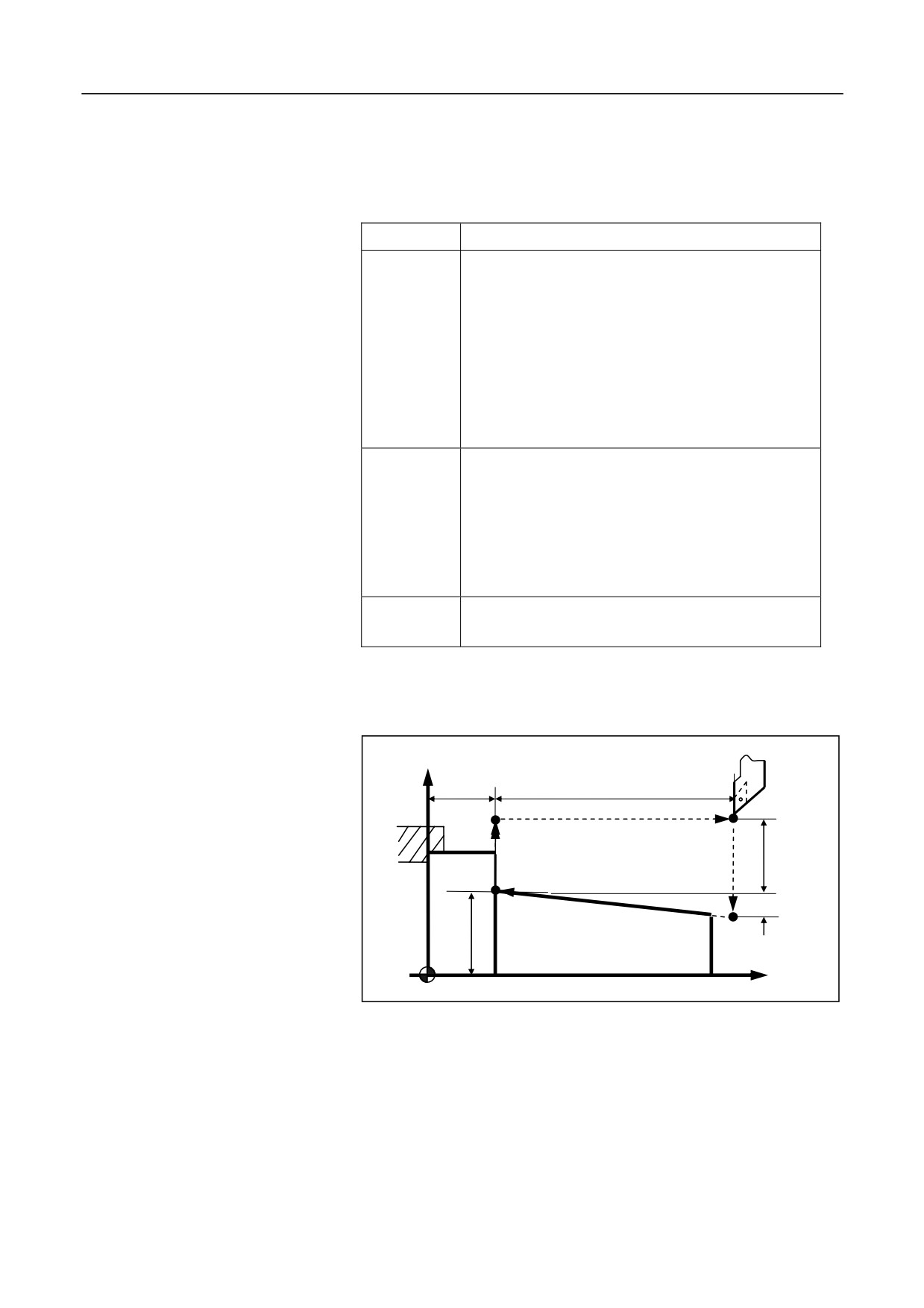
G80 X_/U_ Z_/W_ I_ F_
Parameter
Description
X/U Z/W
The cutting end point C at the workpiece coordinate
Conical surface cutting
system for absolute value programming;
The relative distance from the cutting end point C to
the cycle start point A for the incremental value
programming.
Use U and W to express them in the blueprint and
the direction of path 1 and 2 determine whether it is
a positive or a negative value.
I
The radius difference between the cutting start point
B and the end point C. Either in the absolute value
programming or in the incremental value
programming, the sign (+ or -) of the difference
value determines whether the value of I is positive
or negative.
F
Feed speed (indicates to move at the speed specified
by F) (mm/min)
The tool moves along the path AĺBĺCĺDĺA. See the figure below:
+X
z
w
D
4R
A
3F
1R
u/2
C
i
2F
x/2
B
+Z
241
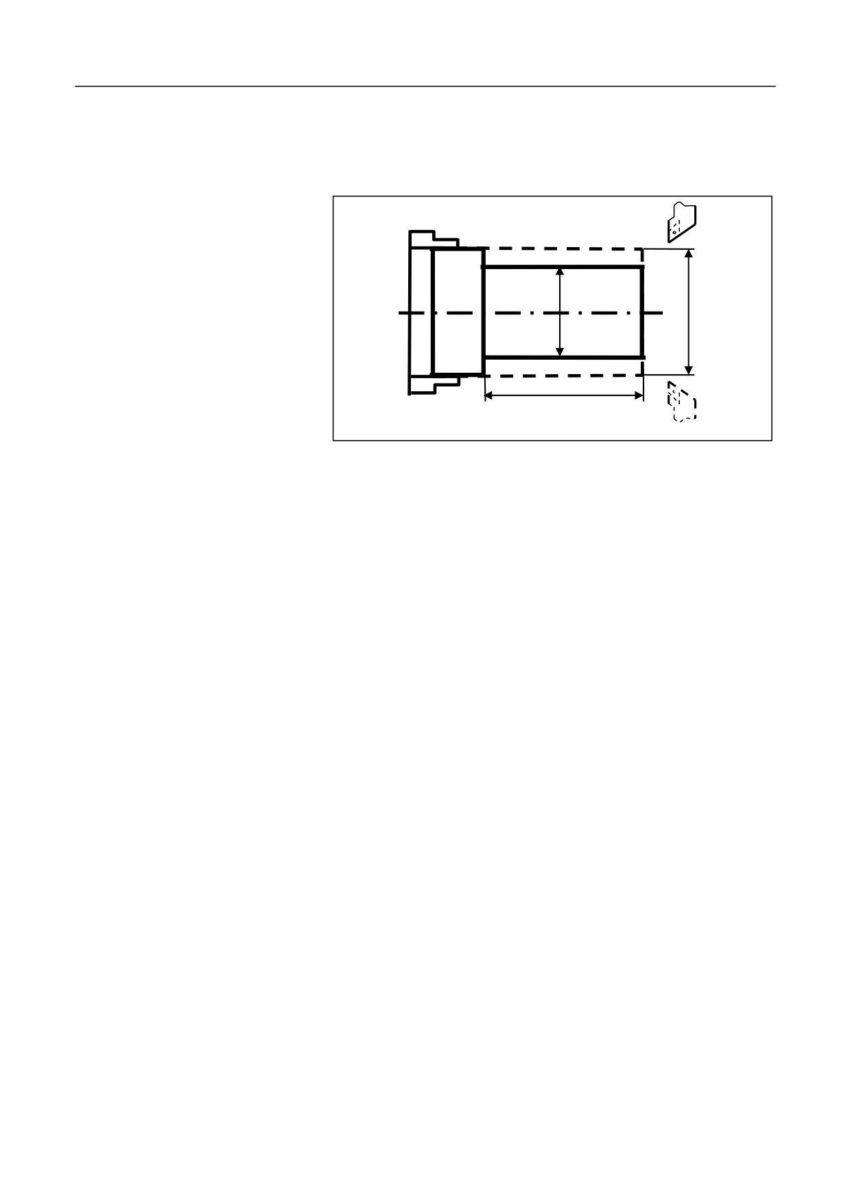
12. Fixed Cycle
Conduct machining for the workpiece as shown in the figure below: use
G80 to conduct rough and finish machining for simple cylindrical parts.
Example 1
ĭ30
ĭ35
50
%3320
N1 T0101
N2 M03 S460
N3 G00 X90Z20
N4 X40 Z3
N5 G80 X31 Z-50 F100
N6 G80 X30 Z-50 F80
N7 G00X90 Z20
N8 M30
Example 2:
Conduct machining for the workpiece as shown in the figure below: use
G80 to conduct rough or finish machining for simple conical parts.
242
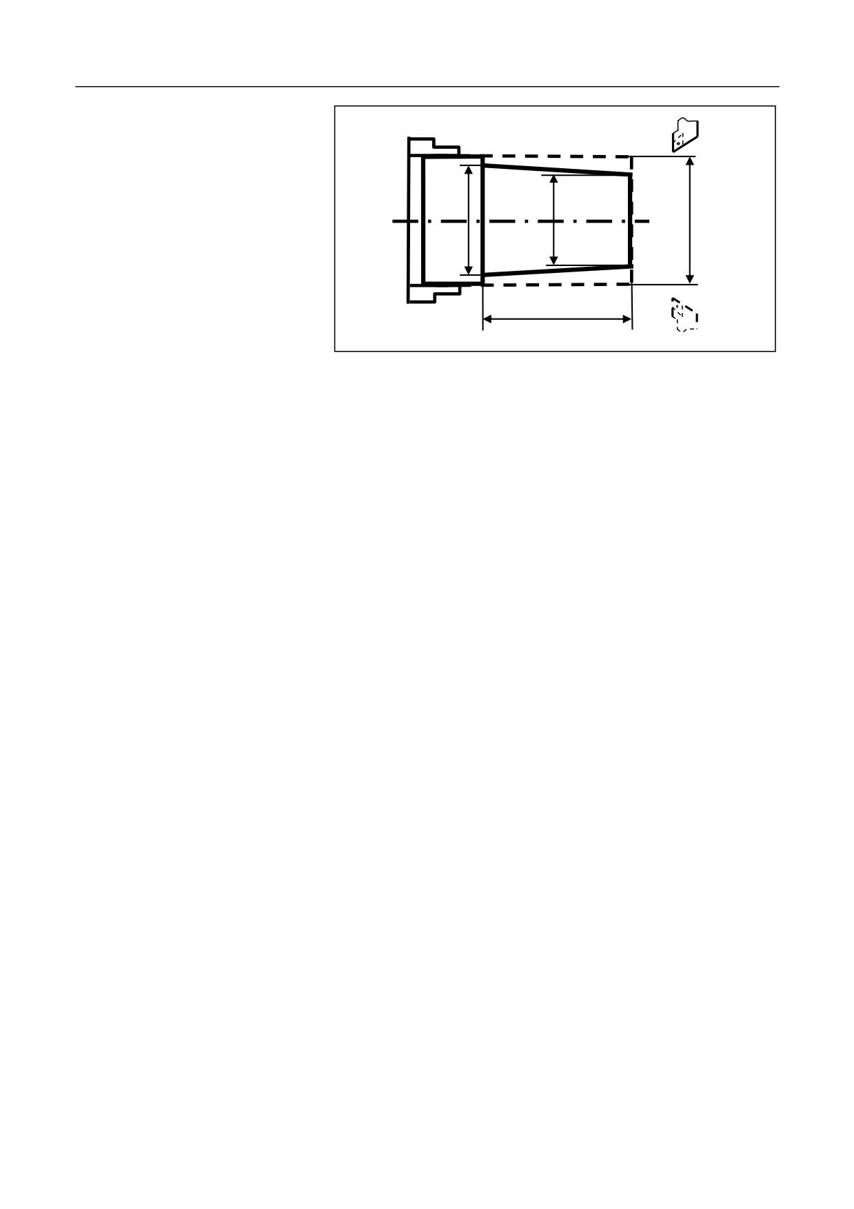
12. Fixed Cycle
ĭ30
ĭ26
ĭ35
50
%3321
N1 T0101
N2 G00 X100Z40 M03 S460
N3 G00 X40 Z5
N4 G80 X31 Z-50 I-2.2 F100
N5 G00 X100 Z40
N6 T0202
N7 G00 X40 Z5
N8 G80 X30 Z-50 I-2.2 F80
N9 G00 X100 Z40
N10 M05
N11 M30
243
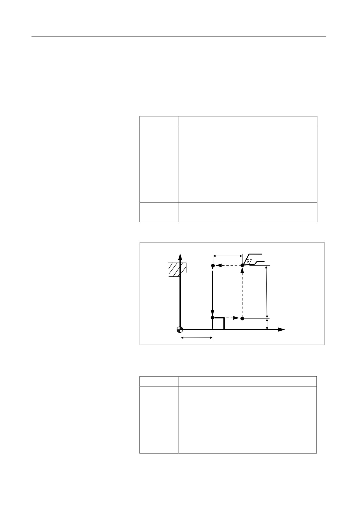
12. Fixed Cycle
12.2.2 End-face cutting cycle (G81)
This cycle can be used for end face cutting and conical face cutting.
End face cutting
G81 X_/U_ Z_/W_ F_
Parameter
Description
X/U Z/W
The cutting end point C at the workpiece coordinate
system for the absolute value programming; The
relative distance from the cutting end point C to the
cycle start point A for the incremental value
programming. Use U and W to express them in the
blueprint and the direction of path 1 and 2
determines whether it is a positive or a negative
value.
F
Feed speed (inidicates to move at the speed
specified by F) (mm/min)
The tool moves along the path AĺBĺCĺDĺA. See the figure below:
w
+X
Cutting
B
start point
1R
A
Cycle start point
2F
4R
u/2
Cutting
3F
C
end point
D
Tool exit
x/2
+Z
z
point
Conical face cutting
G81 X_/U_ Z_/W_ K_ F_
Parameter
Description
X /U Z/W
The cutting end point C at the workpiece coordinate
system for absolute value programming; The
relative distance from the cutting end point C to the
cycle start point A for the incremental value
programming. Use U and W to express them in the
blueprint and the direction of path
1 and
2
determines whether it is a positive or a negative
244