HNC-818. User Manual - page 6
12. Fixed Cycle
Parameter
Description
X Y
The circle center coordinate.
Z
Hole bottom coordinate.
R
The coordinate value of the reference point R for absolute
programming, or the incremental value of the reference
point R to the initial point B for incremental programming.
I
Circle radius.
J
The initial angle for drilling hole, positive in the counter
clockwise direction.
N
The number of holes. The positive value for the counter
clockwise drilling and negative value for the clockwise
drilling.
Q
Feed depth for each time, orientation distance.
K
When conducting feeding again after a tool exit, the
distance away from the previous machining plane while the
rapid feed is changed to the cutting feed.
P
The duration that the tool remains at the hole bottom. Unit:
millisecond
An error is reported when the value of Q is greater than 0 or
K is less than 0; An error is reported when the tool feed
distance Q is less than the tool exit distance K. When Q or
K is 0 or is not defined, G81 center drilling cycle is
executed for each hole, and P is invalid. When the values of
Q and K are correct , G83 deep hole machining cycle is
executed for each hole.
F
Define cutting feed speed.
L
The repeat count (Generally used for multi-hole machining,
and therefore X or Y is incremental value. It is optional
when L=1.).
On the X, Y plane, drill four holes in the counter clockwise direction on
the four axes(+X, -X, +Y, -Y). This operation is executed twice, and G81
is executed for drilling at the hole bottom.
Example 1
G98 G70 X10 Y10 Z0 R20 I10 J0 N4 F200 L2
Example 2
152
12. Fixed Cycle
On the X, Y plane, drill four holes in
executed once, and G81 is executed for drilling at the hole bottom.
the clockwise direction with thangle
G99 G70 X10 Y10 Z10 R50 I10 J45 N-4 F200
of
45 degrees. This operation is
On the X, Y plane, drill four holes in the clockwise direction, with the
angle of
-45 degrees. This operation is executed once, and G81 is
executed for drilling at the hole bottom.
Example 3
G99 G70 X10 Y10 Z10 R50 I10 J-45 N-4 F200
Example 4
On the X, Y plane, drill four holes in the clockwise direction with the
angle of -45 degrees. This operation is executed once. The value of Q is
invalid, and G81 is executed for drilling at the hole bottom.
G99 G70 X10 Y10 Z10 R50 I10 J-45 N-4 Q-10 F200
Example 5
On the X, Y plane, drill four holes in the clockwise direction with the
angle of
-45 degrees. This operation is executed once, and G81 is
executed for drilling at the hole bottom.
Example 6
G99 G70 X10Y10Z10R50 I10J-45N-4 Q0 F200
G99 G70 X10Y10Z10R50 I10J-45N-4 K0 F200
G99 G70 X10Y10Z10R50 I10J-45N-4 Q0K0 F200
On the X, Y plane, drill four holes in the clockwise direction with the
angle of
-45 degrees. This operation is executed once, and G83 is
executed for deep hole cycle.
G99 G70 X10Y10Z10R50 I10J-45N-4 Q-10 K5 F200
153
12. Fixed Cycle
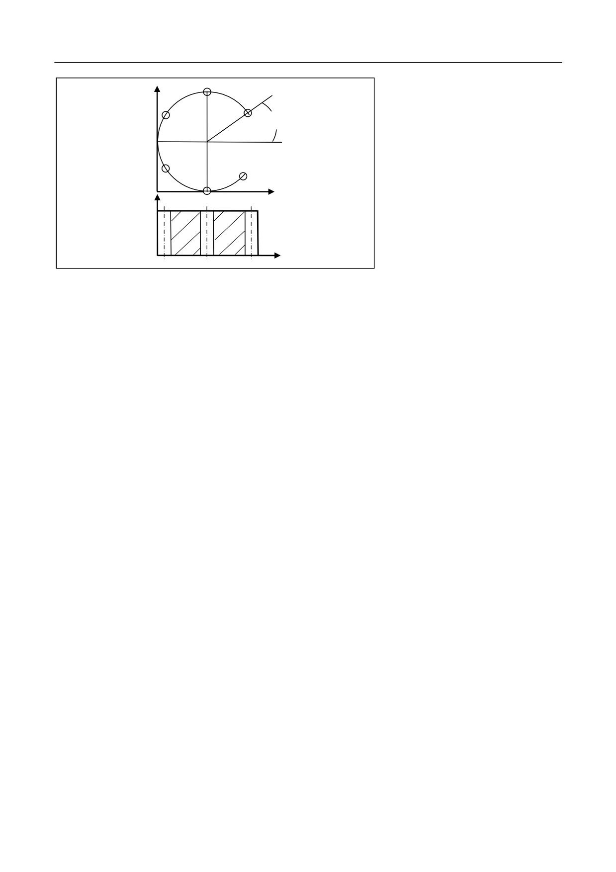
%3358
Y
N10 G55 G00 X0 Y0 Z80
30 degrees
40
X
Z
40
N20 G98G70G90X40Y40R35Z0I40J30N6P2000Q-10K5F100
30
N30 G90 G00 X0 Y0 Z80
X
N40 M30
Use ĭ10 drilling bit for the
machining of the holes as shown in
the figure.
154
12. Fixed Cycle
12.1.2 Arc Drilling Cycle (G71)
Decription
I and the center being the coordinate
(X, Y). Divide the circle into N
equal parts based on the angle J and the X axis. Conduct drilling for N
holes per O degrees, starting from the point where the angle from the A
axis is J. Execute fixed cycle of G81 or G83 based on the value of Q, K
for each hole. The movement between holes is performed through G00.
G71 is a modal code, and the command following it is non-modal.
In the circumference with the radius
Foramt
(G98/G99) G71 X_ Y_ Z_ R_ I_ J_ O_ N[Q_K_P] _ F_ L_
Parameter
Description
X Y
The center coordinate for the arc.
Z
Hole bottom coordinate.
R
The coordinate value of the reference point R for
absolute programming, or the incremental value of the
reference point R to the initial point B for incremental
programming.
I
Arc radius.
J
The initial drilling hole angle, positive in the counter
clockwise direction
O
The angle between each hole. The positive value for the
counter clockwise drilling and negative value for the
clockwise drilling.
N
The number of holes, including the start hole.
Q
Feed depth for each time, orientation distance.
K
When conducting feeding again after a tool exit, the
distance away from the previous machining plane while
the rapid feed is changed to the cutting feed.
P
The duration that the tool remains at the hole bottom.
Unit: millisecond
An error is reported when Q is greater than 0 or K is less
than 0; An error is reported when the tool feed distance
Q is less than the tool exit distance K. When Q or K is 0
or is not defined, execute G81 center drilling cycle for
each hole, and P is invalid. When the values of Q and K
are correct, G83 deep hole machining cycle is executed
for each hole and P is valid.
F
Define cutting feed speed.
155
12. Fixed Cycle
L
The repeat count (Generally used for multi-hole
machining, therefore X or Y is incremental value. L is
optional.)
The total arc angle (N x O) cannot be greater than or equal to 360
degrees, otherwise the command will not be executed.
Attention
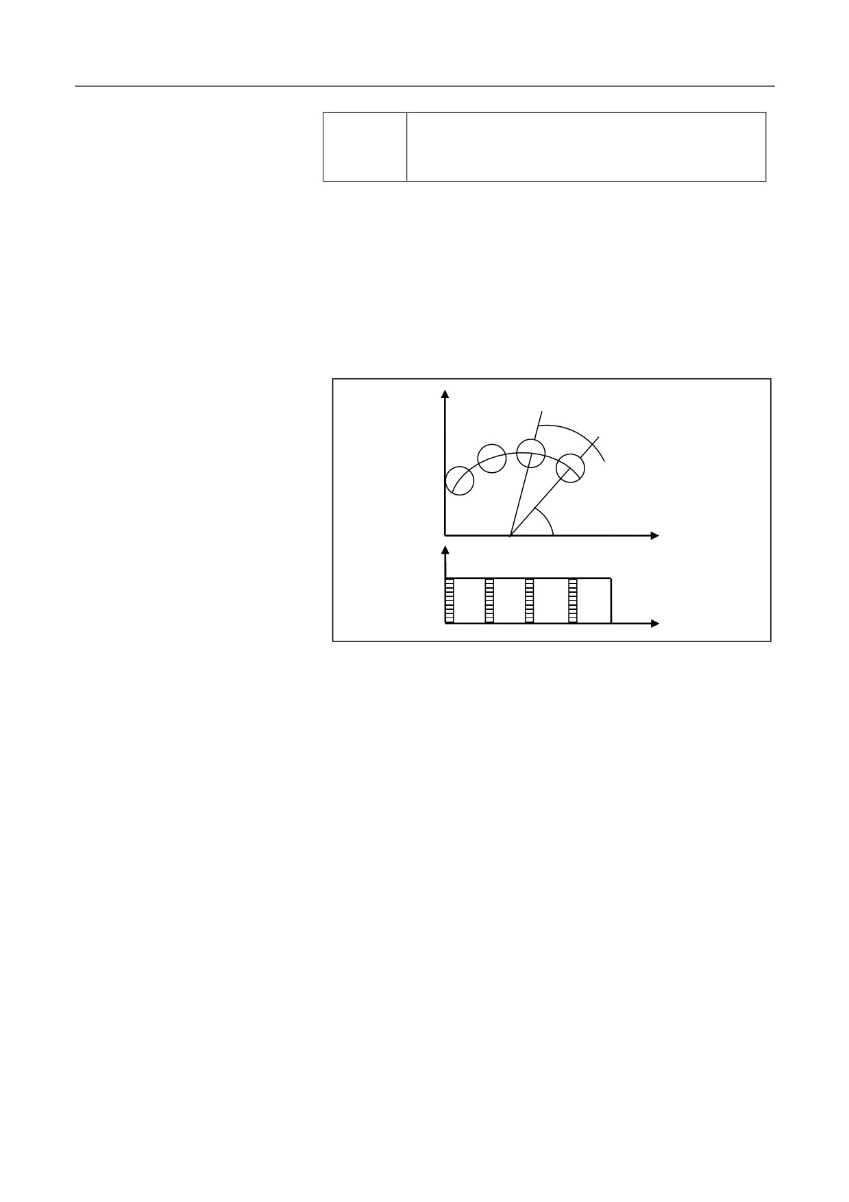
Use ĭ10 drilling bit for the drilling of the holes as shown in the figure:
Example
Y
28 degrees
55 degrees
X
40
Z
20
X
%3359
N10 G55 G00 X0 Y0 Z80
N20 G98G71G90X40Y0G90R25Z0I40J55O28N4P2000Q-10K5F100
N30 G90 G00 X0 Y0 Z80
N40 M30
156
12. Fixed Cycle
12.1.3 High-Speed Deep-Hole Drilling Cycle (G73)
Example
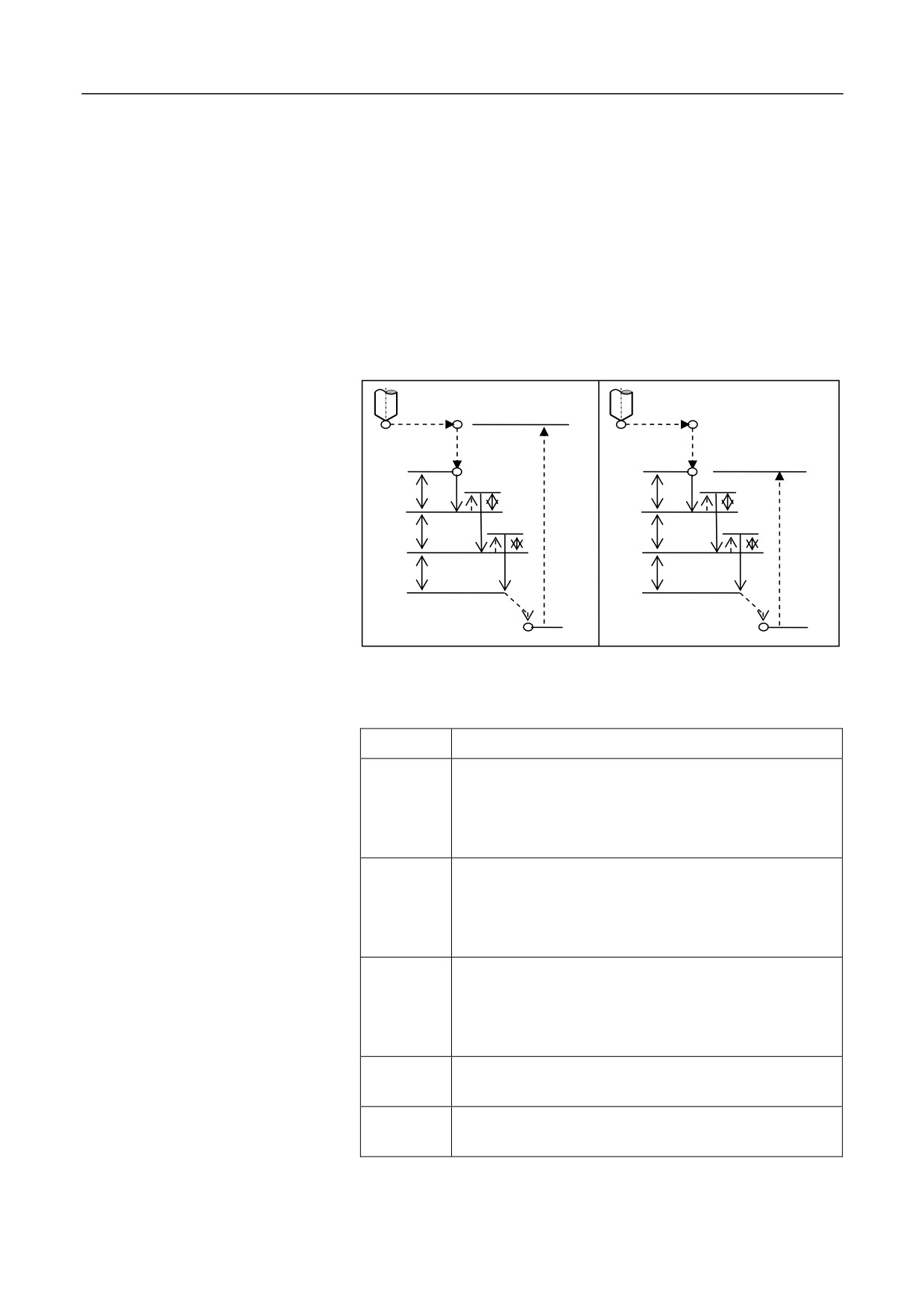
The fixed cycle is used for the intermittent feed along Z axis, which is
prone to chip-breaking, chip-removal, coolant adding, and small amount
of tool exit. It is applicable for high-speed deep-hole drilling.
The figure below shows the operation action sequence of G73. The
dotted line represents rapid positioning, q represents each feed depth,
and k represents each tool exit value.
Initial plane
Plane of point R
Point R
Point R
q
q
k
k
G9
G99
q
q
k
k
q
q
Point Z
Point Z
Format
(G98/G99) G73 X_ Y_ Z_ R_ Q_ P_ K_ F_ L_;
Parameter
Description
X Y
The coordinate value of the hole center in the XY plane
for absolute programming
(G90), or the incremental
value of the hole center to the start point in the XY plane
for incremental programming (G91).
Z
The coordinate value of the hole bottom point Z for
absolute programming (G90), or the incremental value
of the hole bottom point Z to the reference point R for
incremental programming (G91).
R
The coordinate value of the reference point R for
absolute programming (G90), or the incremental value
of the reference point R to the initial point B for
incremental programming (G91).
Q
Drilling depth for each time
(incremental value,
negative).
P
The duration that the tool remains at the hole bottom.
Unit: millisecond.
157
12. Fixed Cycle
K
Each upward tool exit amount
(incremental value,
positive).
F
Drilling feed speed
L
Cycle count (for repetitive drilling)
Operation procedure
1.
The tool moves rapidly to the point B over the hole center.
2.
Move rapidly to the point R, close to the workpiece.
3.
Drill downward at the speed of F, with depth q.
4.
Move upward rapidly, with distance k.
5.
Repeat step 3 and 4 for multiple times.
6.
Drill to the point Z at the hole bottom.
7.
Remain 9 seconds at the hole bottom (spindle remains rotation)
8.
Exit upward rapidly to the point R (G99) or B (G98).
Attention
1.
If the motion amount of Z, K, and Q are zero, this command is not
executed.
2.
|Q|>|K|;
Example
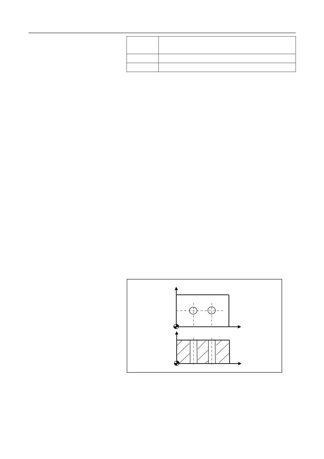
Drilling the hole as shown in the figure below:
Y
25
X
Z
20
40
35
X
%3337
N10 G92 X0 Y0 Z80
N15 M03 S700
158
12. Fixed Cycle
N20 G00 Y25
N30 G98 G73 G91 X20 G90 R40 P2000 Q-10 K2 Z-3 L2 F80
N40 G00 X0 Y0 Z80
N45 M30
159
12. Fixed Cycle
12.1.4 Reverse Tapping Cycle (G74)
Description
The spindle motor and servo motors are running in the position control
mode. The tapping is conducted by the interpolation between the tapping
axis and spindle. The spindle feeds the distance of one thread lead along
the tapping axis per rotation. The feeding does not change even during
acceleration or deceleration.
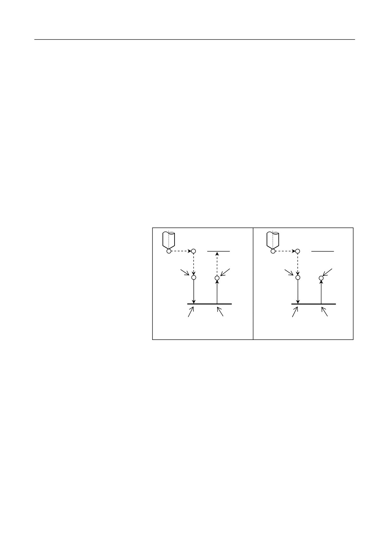
The action defined by G74 is as shown in the figure below. Move rapidly
to the point "R" after positioning along X and Y axis. The spindle rotates
in the counter clockwise (CCW) direction, and tapping is conducted
from the point R to Z. After the tapping is completed, the spindle stops
and the system starts the mode of pause. Then the spindle rotates in the
clockwise (CW) direction, the tool exits back to the point R, and the
spindle stops. The tool will finally move rapidly to the initial position in
the G98 mode.
Initial plane
Initial plane
Spindle CCW
Spindle stop
Spindle CCW
Spindle stop
Point
Point
R
R
Point Z
Point Z
P
P
Spindle stopl
Spindle CW
Spindle stopl
Spindle CW
G74 (G98)
G74 (G99)
In the rigid tapping mode, the servo
spindle motor controls the tapping.
Format
(G98/G99)G74 X_ Y_ Z_ Q_ R_ P_ F_ L_H_J_;
160
12. Fixed Cycle
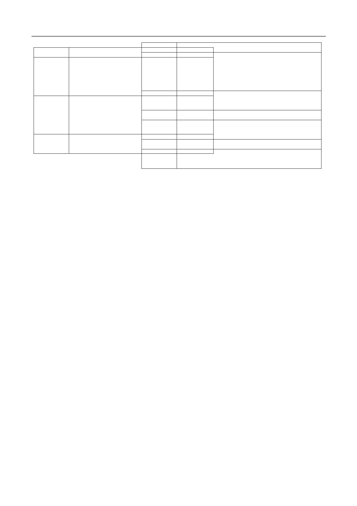
Parameter
Description
Parameter
Description
R
The absolute
position of the point R for absolute
X Y
The absolute position of the hole for absolute
programming (G90), or the distance from the point R
programming (G90), or the
distance from the current
to the initial plane for incremental programming
tool position to the hole for
incremental programming
(G91).
(G91).
P
The duration
that the tool remains at the hole bottom.
Z
The absolute position of the hole bottom for absolute
Unit: millisecond.
programming (G90), or the
distance from the hole
F
Define thread lead.
bottom to the point R for incremental programming
H
H1: segment
tapping, exits to the R plane each time.
(G91).
H2: directly drills to the hole bottom.
Q
The amount of each feed during segment
tapping.
L
Repeat count
(It is optional when L=1.)
Leave it blank in the H2 mode.
J
J1: A axis tapping; J2: B axis tapping; J3 C: axis
tapping
F (feed speed) during tapping
(F) specified in the programming is invalid. The feed speed along the
tapping axis is derived from: speed feed = spindle speed x thread lead
During rigid tapping, the feed speed
Tapping mode
C axis tapping: take the servo spindle as the C axis, and conduct tapping
by interpolation, to achieve high-speed high-precision tapping.
Attention
1.
The tapping axis must be the Z axis.
2.
The point Z must be lower than the plane of point R; otherwise, an
alarm will be reported.
161
12. Fixed Cycle
3.
The G74 command data is
saved as modal data.
4.
When the motion amount of Z
is zero, the cycle is not
executed.
5.
During reverse tapping, the
operations
on feed rate
adjustment,
spindle
rate
adjustment, and feed hold is
invalid.
6.
Before
specifying
reverse
tapping with G74, change the
control mode of the spindle
servo motor from speed control
to the position control by using
the STOC command. After
tapping, you may use the CTOS
clockwise direction.
command to change back to the
speed control mode and take the
8.
After executing the rigid tapping with G74, the programmer must
servo spindle as a common
restore the original feed speed; otherwise, the feed speed will be the
spindle.
rigid tapping speed (s*pitch).
7.
Before
specifying
reverse
tapping with G74, use the
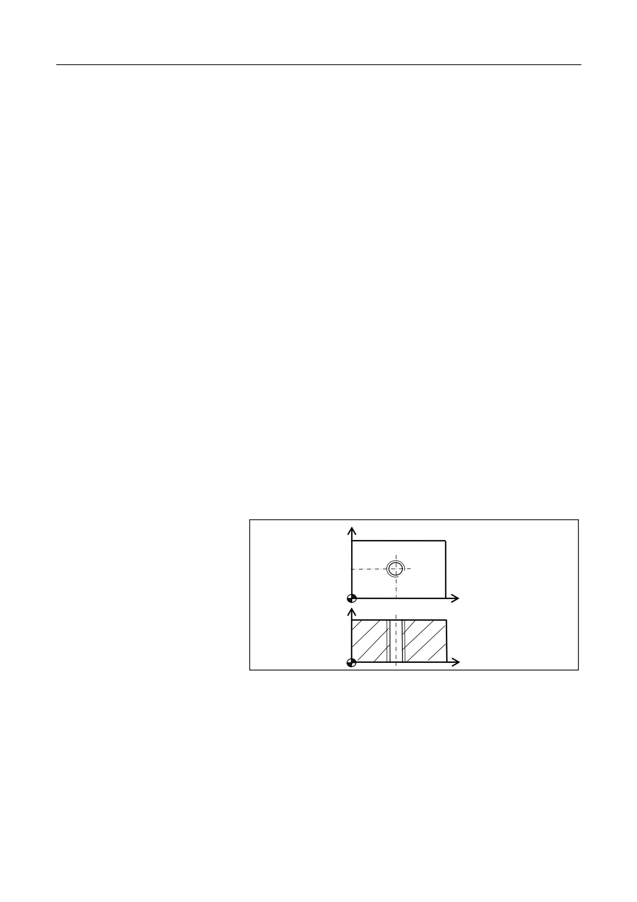
Use M10 x 1 for anti-tapping
corresponding M command to
rotate the spindle in the counter
Y
X
50
Z
35
X
%3339
Example
G92 X0 Y0 Z80 F200
M04 S300
STOC
G98G74X50Y40R40P10000G90Z-5F1
CTOS
162
12. Fixed Cycle
G0 X0 Y0 Z80
M30
163
12. Fixed Cycle
12.1.5 Fine-Boring Cycle (G76)
Description
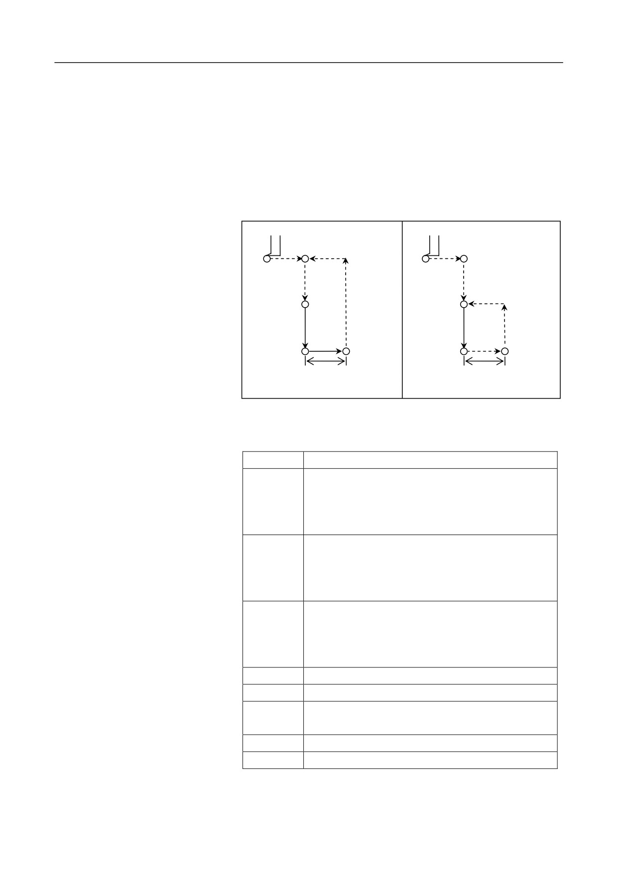
During finish boring, after the spindle stops orientation at the hole
bottom, it moves away from the tool nose, then the tool quickly exits.
The value of movement away from the tool nose is specified by (I, J),
which can only be positive. The value of (I, J) is modal, and the
movement direction is determined during tool installation.
Initial plane
Plane of point R
G98
Point R
Point R
G99
Point Z
Point Z
Offset value (I, J)
Offset value (I, J)
Format
(G98/G99) G76 X_ Y_ Z_ R_ I_ J_ P_ F_ L_;
Parameter
Description
X Y
The absolute position of the hole for absolute
programming (G90), or the distance from the current
tool position to the hole for incremental programming
(G91). UW programming is not supported.
Z
The absolute position of the hole bottom along Z axis
for absolute programming (G90), or the distance from
the hole bottom to the point R for incremental
programming (G91).
R
The absolute position of the point R along Z axis for
absolute programming (G90), or the distance from the
point R to the initial plane for incremental
programming (G91).
I
Offset value along X axis, positive only.
J
Offset value along Y axis, positive only.
The duration that the tool remains at the hole bottom.
P
Unit: millisecond.
F
Cutting feed speed.
L
Repeat count (It is optional when L=1.)
164
12. Fixed Cycle
1.
The tool moves rapidly to the point B over the hole center.
2.
Move rapidly to the point R, close to the workpiece.
Operation procedure
3.
Conduct boring downward at the speed of F, to the point Z at the
hole bottom.
4.
Remain at the hole bottom for P seconds (The spindle remains
rotation).
5.
The spindle conducts orientation and stops rotation.
6.
The boring tool rapidly moves away form the tool nose with the
distance specified by I or J.
7.
Exit upward rapidly to the point R (G99) or B G98).
8.
Move rapidly in the positive direction of the tool nose with the
distance specified by I or J, and the tool moves back to the point R
or B over the hole center.
9.
The spindle restores the clockwise rotation.
Attention
1. The boring axis must be the Z axis.
2. The point Z must be lower than the plane of point R; otherwise, an
alarm will be reported.
3. The G76 command data is saved as modal data.
4. Before using the command of G76, use the corresponding M
command to rotate the spindle.
Example
165
12. Fixed Cycle
Y
30
15
X
20
40
Z
35
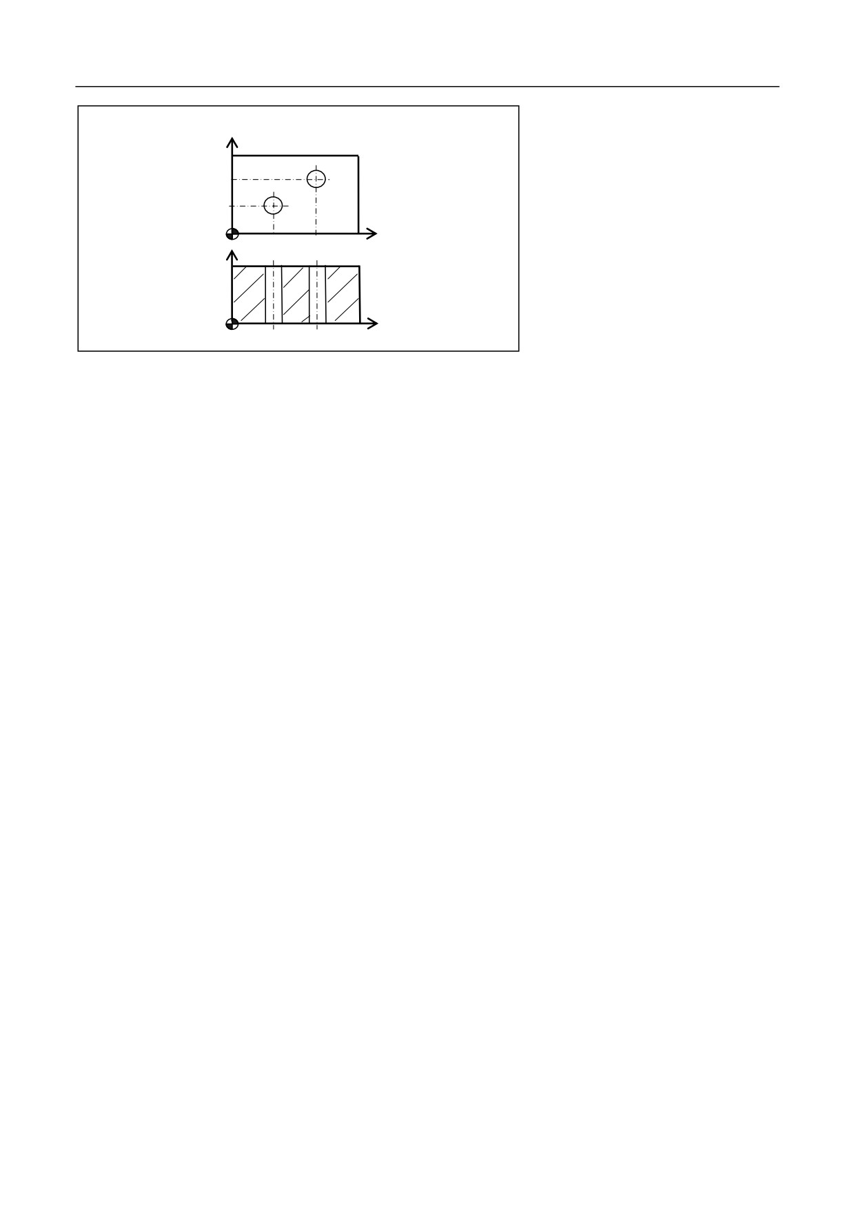
Use
the single-margin boring tool.
X
%3341
N10 G54
N12 M03 S600
N15 G00 X0 Y0 Z80
N20 G98G76X20Y15R40P2000I5Z-4F100
N25 X40Y30
N30 G00 G90 X0 Y0 Z80
N40 M30
166
12. Fixed Cycle
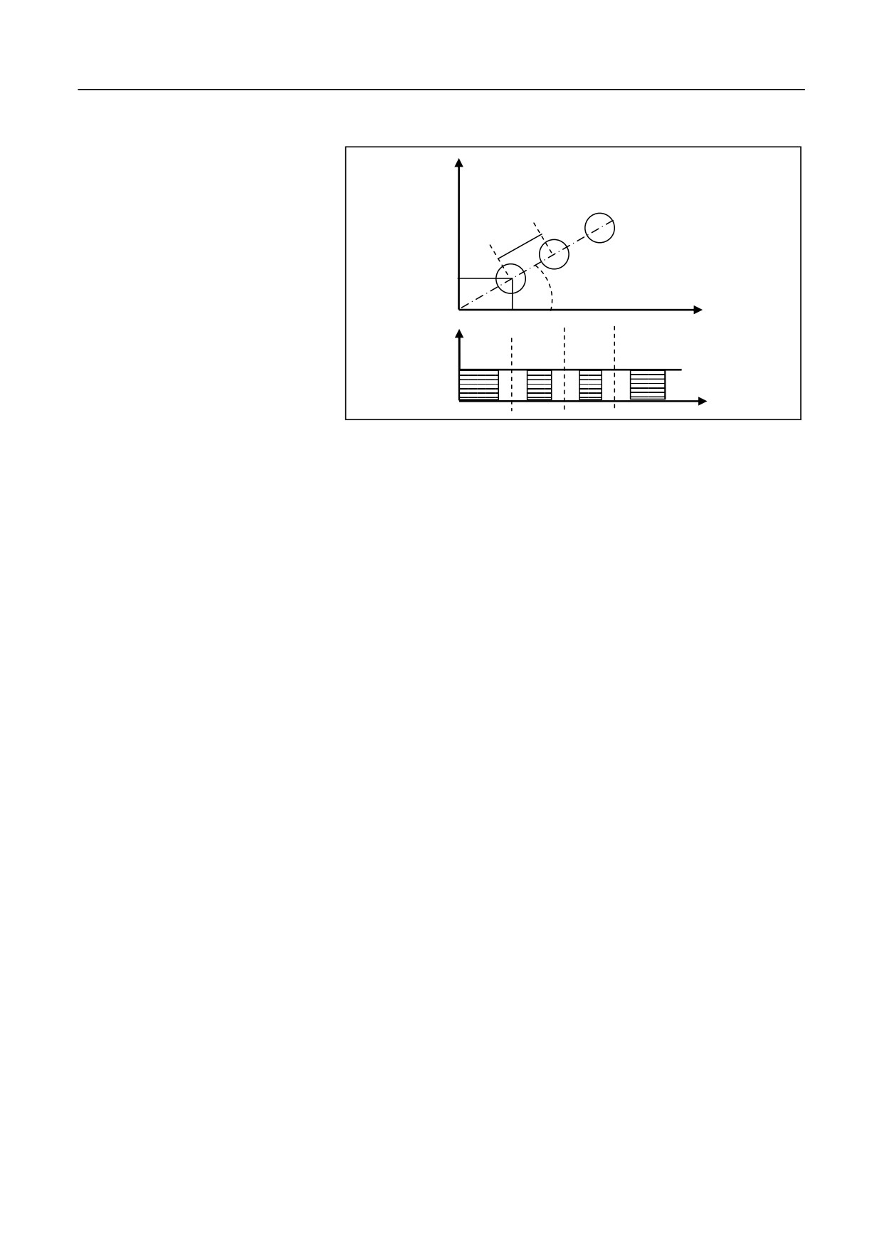
12.1.6 Angular Linear Drilling Cycle (G78)
Description
Divide the oblique line which rotates J degrees around axis X into N
holes with the interval distance of I. Starting from the point defined by X,
Y, conduct the drilling cycle for each hole. Execute G81 and G83 fixed
cycle based on the value of Q, K for each hole. The movement between
holes is conducted through G00. G78 is a modal code, and the command
following it is non-modal.
Format
(G98/G99) G78 X_ Y_ Z_ R_ I_ J_ N_[Q_K_P]_ F_ L_
Parameter
Description
X Y
The coordinate of the first hole.
Z
The coordinate of the hole bottom.
R
The absolute position of the reference point R for
absolute programming (G90), or the distance from the
reference point R to the initial point B for incremental
programming (G91).
I
The distance between two successive hole centers.
J
The start angle formed by the oblique line and the
positive X axis, which is positive in the counter
clockwise direction.
N
The number of holes including the start hole.
Q
Feed depth for each time, orientation distance.
K
When conducting feeding again after a tool exit, the
distance away from the previous machining plane while
the rapid feed is changed to the cutting feed.
P
The duration that the tool remains at the hole bottom.
Unit: millisecond
An error is reported when Q is greater than 0 or K is less
than 0; An error is reported when the tool feed distance
Q is less than the tool exit distance K. When Q or K is 0
or is not defined, execute G81 center drilling cycle for
each hole, and P is invalid. When the values of Q and K
are corrective, execute G83 deep hole machining cycle
for each hole, and P is valid.
F
Define cutting feed speed.
L
The repeat count (Generally used for multi-hole
machining,and therefore X or Y is incremental value. (It
is optional when L=1.)
167
12. Fixed Cycle
Example
Use ĭ10 drilling bit to drill the holes as shown in the figure:
Y
20
10
30 degrees
X
20
Z
10
X
%3360
N10 G55 G00 X0 Y0 Z80
N20 G98G78G90X20Y10G90R15Z0I20J30N3P2000Q-10K5F100
N30 G90 G00 X0 Y0 Z80
N40 M30
168
12. Fixed Cycle
12.1.7 Chessboard Drilling Cyle (Drilling along X Axis First) (G79)
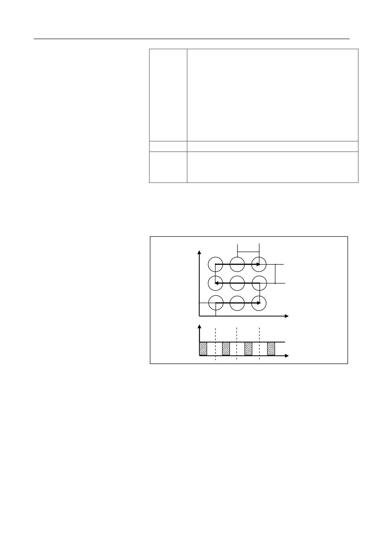
Description
Starting from the point defined by X, Y, conduct drilling for N holes in
the direction parallel to the X-axis with the interval distance of I. Then
conduct drilling in the direction of the X axis with an interval specified
by J along the Y axis. This operation is repeated for O times. Execute
G81 and G83 fixed cycle based on the value of Q, K for each hole. The
movement between holes is performed through G00. G79 is a modal
code, and the command following it is non-modal.
Format
(G98/G99) G79 X_ Y_ Z_ R_ I_ N_ J_ O_[Q_K_P]_ F_ L_
Parameter
Description
X Y
The coordinate of the first hole.
Z
The coordinate of the hole bottom.
R
The coordinate value of the reference point R for absolute
programming
(G90), or the incremental value of the
reference point R to the initial point B for incremental
programming (G91).
I
The distance between two successive hole centers in the X
axis direction. The positive value indicates the drilling along
the positive X axis direction while the negative value
indicates the drilling along the negative X axis direction.
N
The number of holes including the start hole in the X axis
direction.
J
The distance between two successive hole centers in the Y
axis direction. The positive value indicates the drilling along
the positive Y axis direction while the negative value
indicates the drilling along the negative Y axis direction.
O
The number of holes including the start hole in the Y axis
direction.
Q
Feed depth for each time, orientation distance.
K
When conducting feeding again after a tool exit, the
distance away from the previous machining plane while the
rapid feed is changed to the cutting feed.
169
12. Fixed Cycle
P
The duration that the tool remains at the hole bottom. Unit:
millisecond
An error is reported when Q is greater than 0 or K is less
than 0; An error is reported when the tool feed distance Q is
less than the tool exit distance K. When Q or K is 0 or is not
defined, execute G81 center drilling cycle for each hole, and
P is invalid. When the values of Q and K are correct,
execute G83 deep hole machining cycle for each hole, and P
is valid.
F
Define cutting feed speed.
L
The repeat count (Generally used for multi-hole machining,
therefore X or Y is incremental value. It is optional when
L=1.)
Example
Use ĭ10 drilling bit for the drilling of the holes as shown in the figure:
15
Y
15
20
X
20
Z
20
X
%3361
N10 G55 G00 X0 Y0 Z80
N20 G98G79G90X20Y20G90R25Z0I15N3J15O3P2000Q-10K5F100
N30 G90 G00 X0 Y0 Z80
N40 M30
170
12. Fixed Cycle
12.1.8 Drilling Cycle (Center Drilling) (G81)
Description
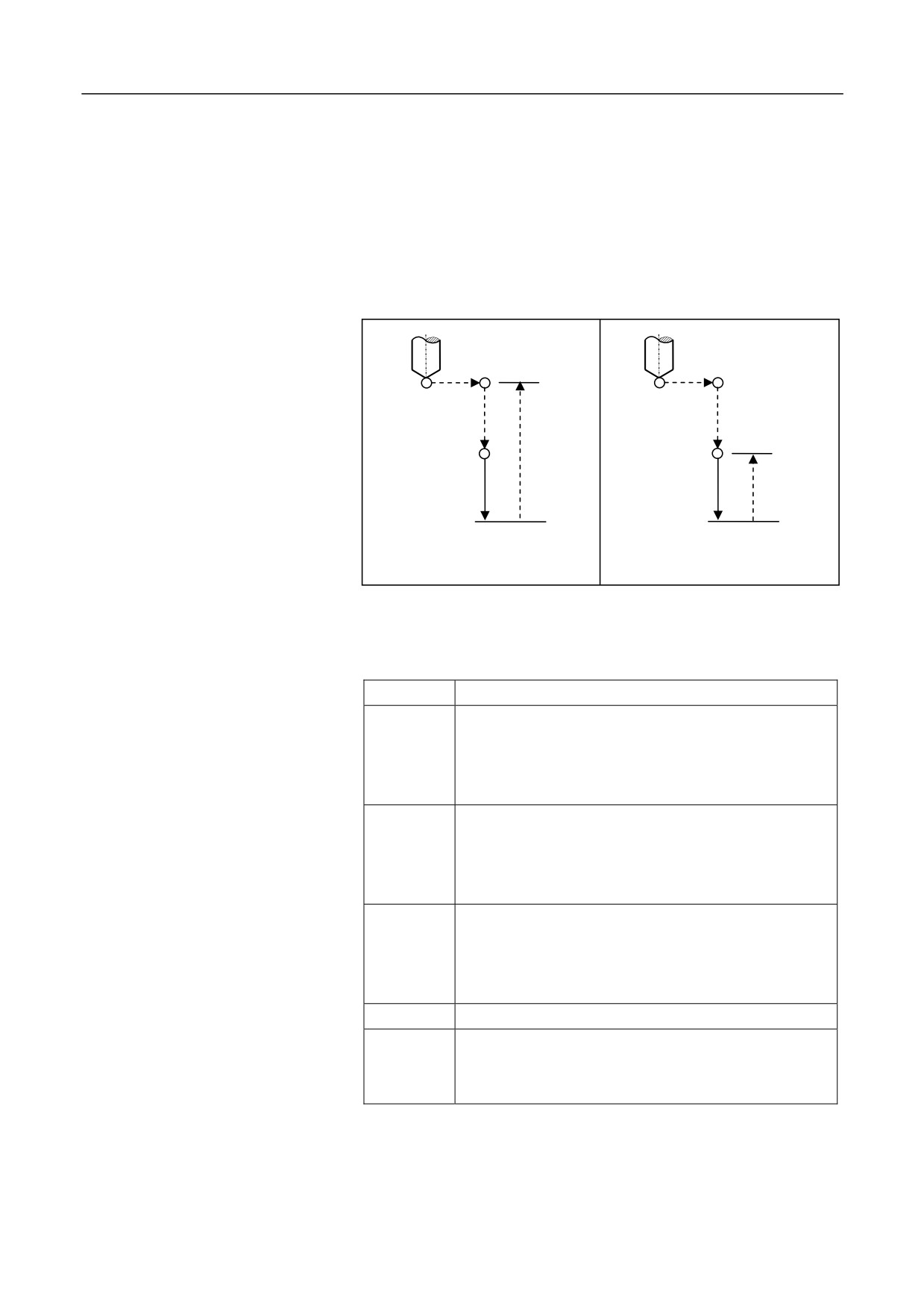
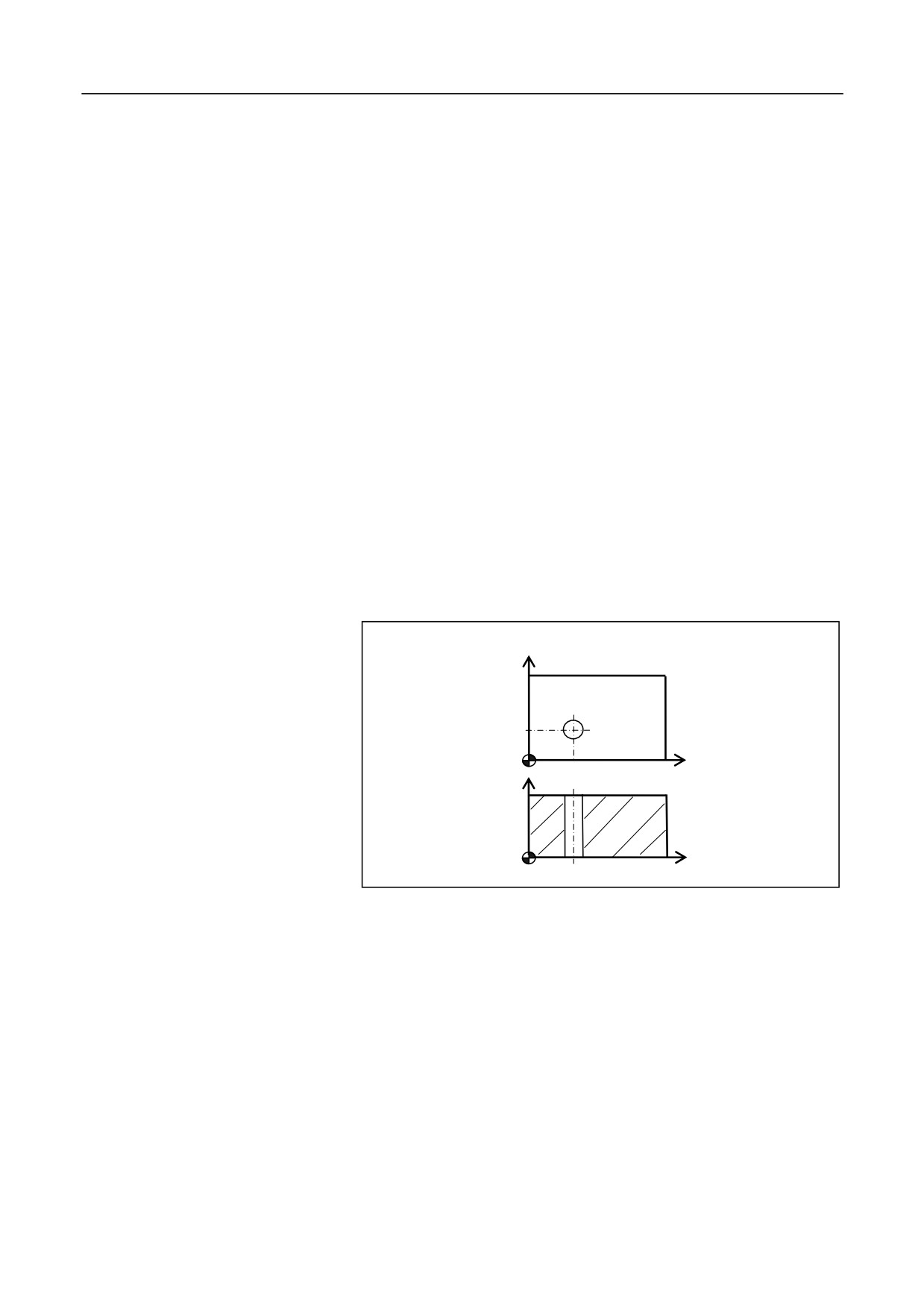
The cycle is used for normal drilling. The cutting feed is executed to the
hole bottom, and then the tool rapidly exits from the hole bottom.
The movement specified by G81 is as shown in the figure below, where
the dotted line indicates rapid positioning:
Initial plane
Plane of point R
Point R
Point R
Point Z
Point Z
G81 (G98)
G81 (G99)
Format
(G98/G99) G81 X_ Y_ Z_ R_ F_ L_ ;
Parameter
Description
X Y
The absolute position of the hole for absolute
programming (G90), or the distance from the current
tool position to the hole for incremental programming
(G91).
Z
The absolute position of the hole bottom along Z axis
for absolute programming (G90), or the distance from
the hole bottom to the point R for incremental
programming (G91).
R
The absolute position of the point R along Z axis for
absolute programming (G90), or the distance from the
point R to the initial plane for incremental
programming (G91).
F
Cutting feed speed.
L
The repeat count
(Generally used for multi-hole
machining, and therefore X or Y is incremental value. It
is optional when L=1.)
171
12. Fixed Cycle
1. The tool moves rapidly to the point B over the hole center.
Operation procedure
2. Move rapidly to the point R, close to the workpiece.
3. Conduct drilling downward at the speed of F, to the point Z at the
hole bottom.
4. The spindle remains the rotation and moves upward rapidly to the
point R (G99) or B (G98).
Attention
1. If the movement amount of Z is zero, the command is not executed.
2. The drilling axis must be the Z axis.
3. The G81 command data is saved as modal data.
4. Before using the command of G81, use the corresponding M
command to rotate the spindle.
Example
Conduct drilling of the holes as shown in the figure below:
Y
30
15
X
20
Z
15
X
%3343
N10 G92 X0 Y0 Z80
N15 M03 S600
N20 G98 G81 G91 X20 Y15 G90 R20 Z-3 L2 F200
N30 G00 X0 Y0 Z80
N40 M30
172
12. Fixed Cycle
12.1.9 Drilling Cycle with Pause (G82)
Description
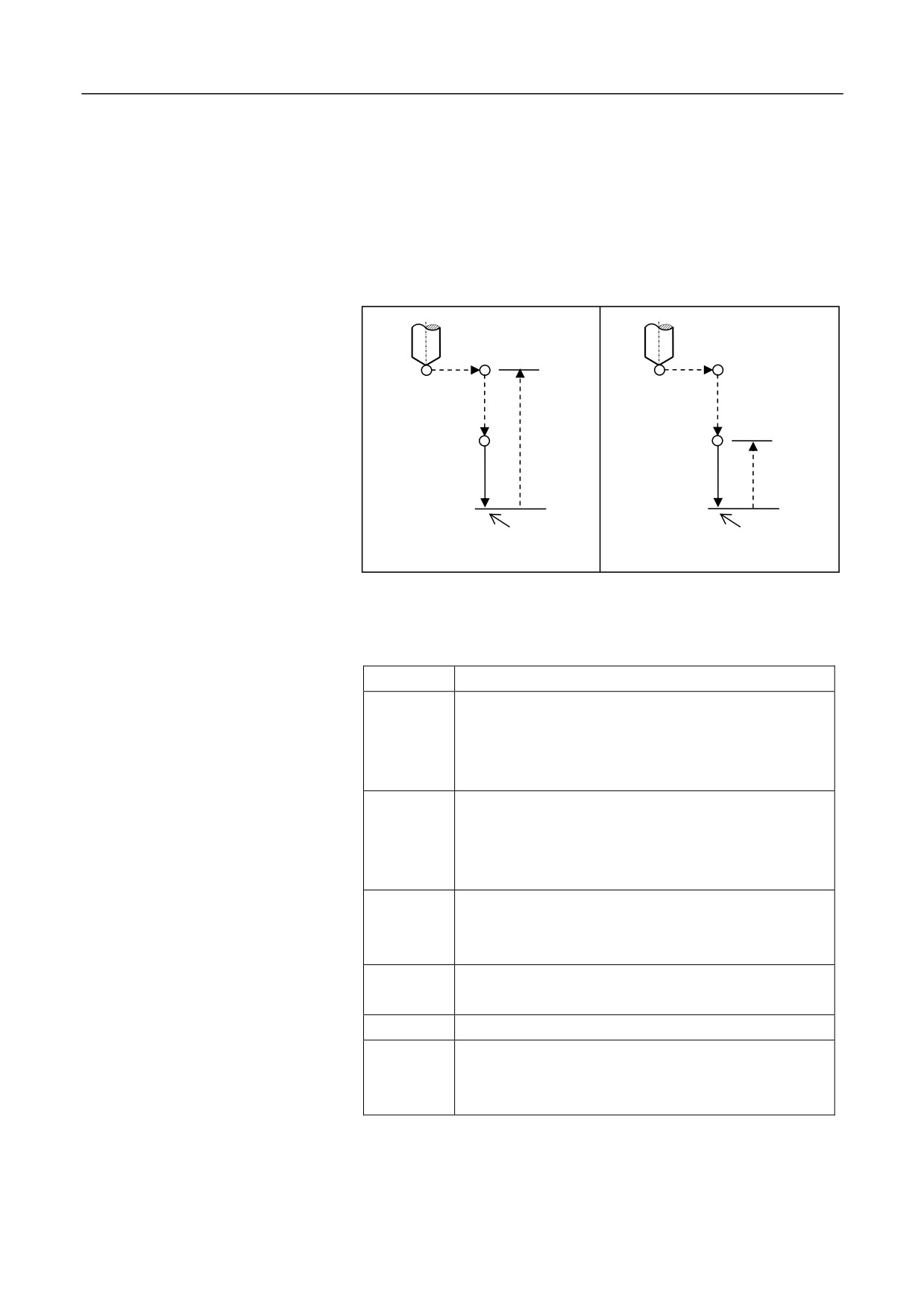
This instruction is mainly used for processing sink holes, blind holes, to
improve the hole depth precision. Except for the pause at the hole bottom,
other operations are similar as that of G81. The figure below shows the
operation of G82:
Initial plane
Plane of point R
Point R
Point R
Point Z
Point Z
Pause
Pause
G82 (G98)
G82 (G99)
Format
(G98/G99) G82 X_ Y_ Z_ R_ P_ F_ L_;
Parameter
Description
X Y
The absolute position of the hole for absolute
programming (G90), or the distance from the current
tool position to the hole for incremental programming
(G91).
Z
The absolute position of the hole bottom along Z axis
for absolute programming (G90), or the distance from
the hole bottom to the point R for incremental
programming (G91).
R
The absolute position of the point R for absolute
programming (G90), or the distance from the point R
to the initial plane for incremental programming (G91).
P
The duration that the tool remains at the hole bottom.
Unit: millisecond
F
Cutting feed speed.
L
The repeat count
(Generally used for multi-hole
machining to simplify programming. It is optional
when L=1.)
173
12. Fixed Cycle
1. The tool moves rapidly to the point B over the hole center.
2. Move rapidly to the point R, close to the workpiece.
Operation procedure
3. Conduct drilling downward at the speed of F, to the point Z at the
hole bottom.
4. Delay P milliseconds with the rotation of the spindle.
5. Move upward rapidly to the point R (G99) or B (G98).
Attention
1. The drilling axis must be the Z axis.
2. If the movement amount of Z is zero, the command is not executed.
3. The G82 command data is saved as modal data.
4. Before using the command of G82, use the corresponding M
command to rotate the spindle.
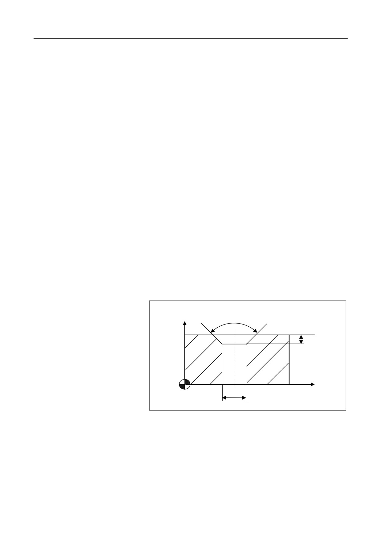
Example
Conduct drilling of the hole as shown in the figure below:
90 degrees
Z
4
35
X
ĭ12
%3345
N10 G92 X0 Y0 Z80
N15 M03 S600
N20 G98 G82 G90 X25 Y30 R40 P2000 Z25 F200
N30 G00 X0 Y0 Z80
174
12. Fixed Cycle
N40 M30
175
12. Fixed Cycle
12.1.10 Deep-Hole Drilling Cycle (G83)
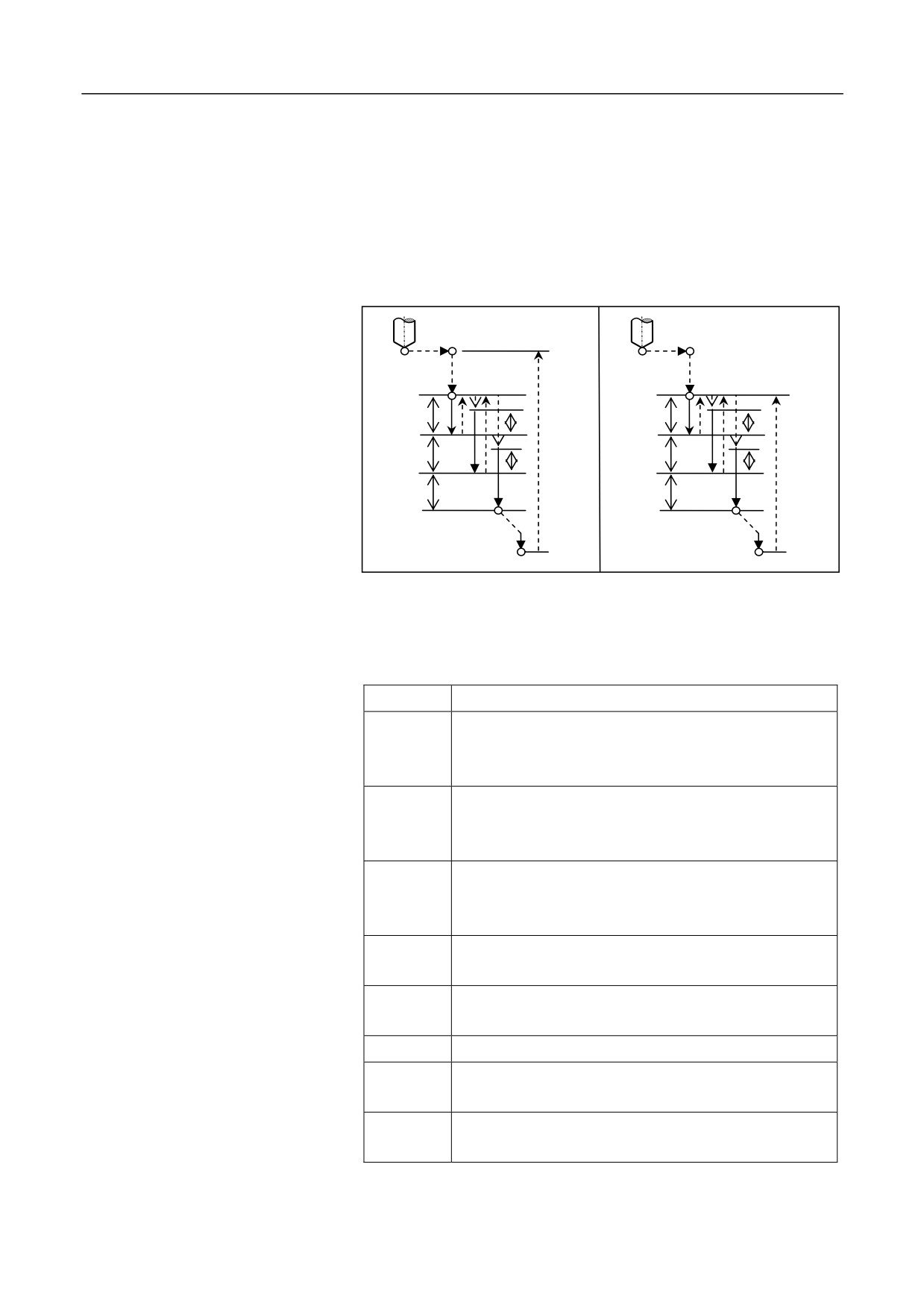
Description
The fixed cycle is used for the intermittent feed along Z axis, which
enables a rapid tool exit to the reference point R with larger retract
amount after each drilling,.It facilitates the chip-removal and coolant
adding. The figure below shows the operation specified by G83:
Initial plane
Point R
Point R
Plane of point R
q
q
k
k
G98
G99
q
q
k
k
q
q
Point Z
Point Z
Format
(G98/G99) G83 X_ Y_ Z_ R_ Q_ K_ F_ L_ P_;
Parameter
Description
X Y
The absolute position of the hole for absolute
programming (G90), or the distance from the current tool
position to the hole for incremental programming (G91).
Z
The absolute position of the hole bottom for absolute
programming (G90), or the distance from the hole bottom
to the point R for incremental programming (G91).
R
The absolute position of the point R for absolute
programming (G90), or the distance from the point R to
the initial plane for incremental programming (G91).
Q
The each downward drilling depth
(incremental value,
negative).
K
The distance away from the upper surface of drilled hole
(incremental value, positive). K cannot be greater than Q.
F
Cutting feed speed.
L
The repeat count (Generally used for multi-hole machining
to simplify programming. It is optional when L=1.)
P
The duration that the tool remains at the hole bottom. Unit:
millisecond
176
12. Fixed Cycle
1. The tool moves rapidly to the point B over the hole center.
2. Move rapidly to the point R, close to the workpiece.
Operation procedure
3. Drill downward at the speed of F, with depth q.
4. Move upward rapidly to the point R.
5. Move downward rapidly to the upper surface of the drilled hole, the
distance is specified with K.
6. Drill downward at the speed of F, with depth (q + k).
7. Repeat the step 4, 5, and 6, and then drills to the hole bottom Z
point.
8. Delay P milliseconds at the hole bottom (spindle remains rotation).
9. Exit upward rapidly to the point R (G99) or B (G98).
Attention
1. The drilling axis must be the Z axis.
2. If the movement amount of Z, Q, and K are zero, the command is
not executed.
3. The G83 command data is saved as modal data.
4. Before using the command of G83, use the corresponding M
command to rotate the spindle.
Example
Conduct drilling of the hole as shown in the figure below:
177
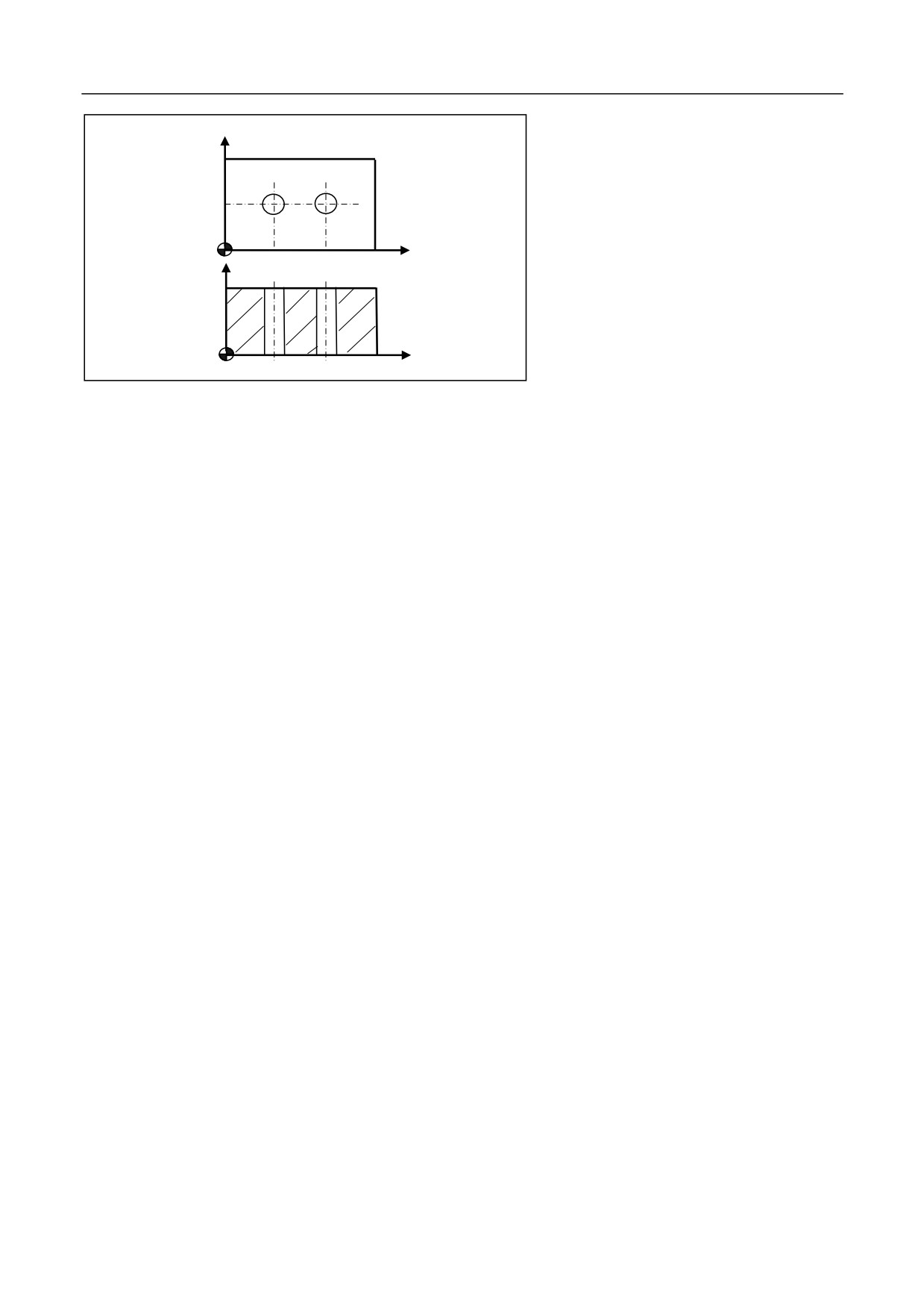
12. Fixed Cycle
Y
25
X
20
40
Z
35
N15 Y25
N20XG98G83G91X20G90R40P2Q-10K5G91Z-43F100L2
N30 G90 G00 X0 Y0 Z80
%3347
N40 M30
N10 G55 G00 X0 Y0 Z80
178
12. Fixed Cycle
12.1.11 Tapping Cycle (G84)
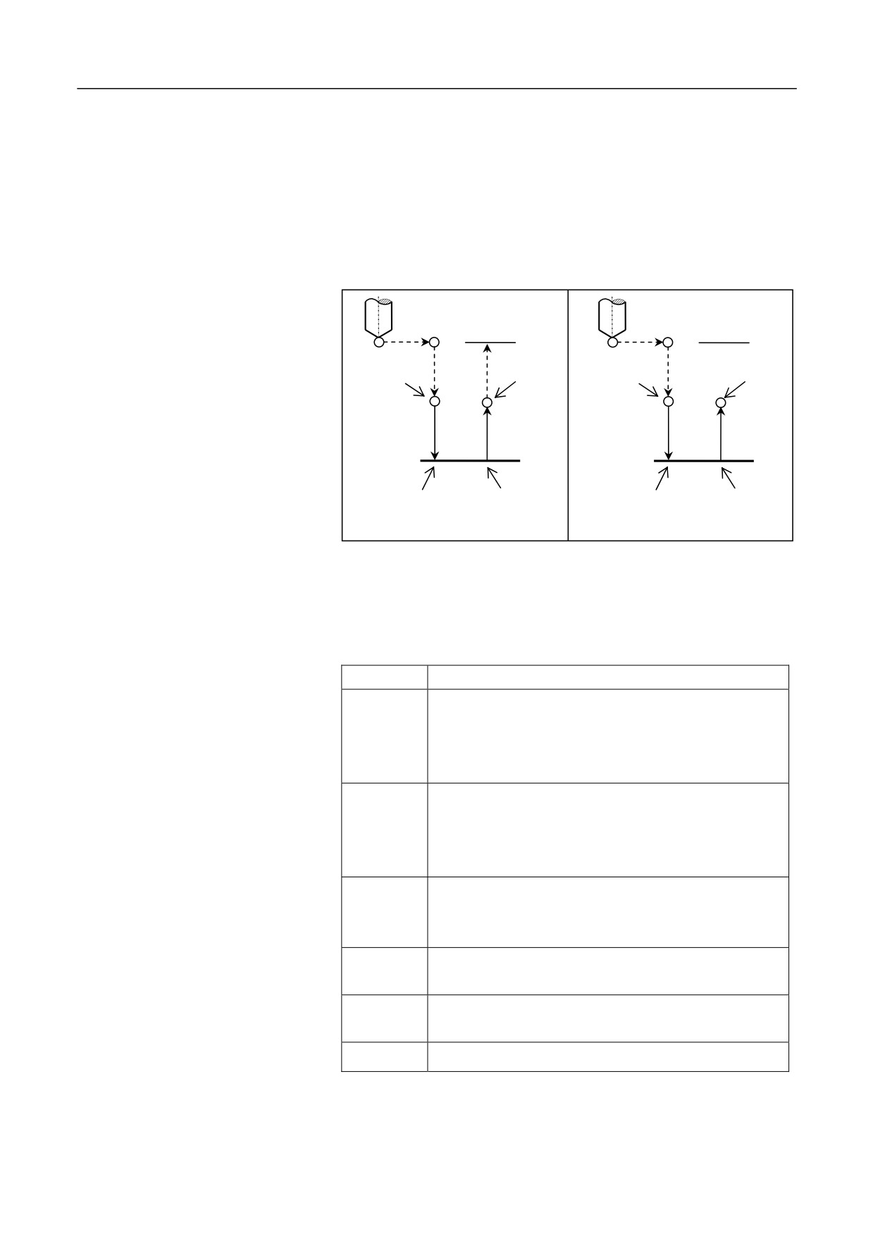
Description
on the same principle. In the G84 mode, the tool taps to the hole bottom
with the spindle rotation in the clockwise direction and then goes back
with the spindle rotation in the counter clockwise direction. See the
figure below:
Initial plane
Initial plane
Spindle CW
Spindle stop
Spindle CW
Spindle stop
Point
Point
R
R
Point Z
Point Z
P
P
Spindle stop
Spindle CCW
Spindle stop
Spindle CCW
G84 (G98)
G84 (G99)
The command G84 and G74 works
Format
G84 X_ Y_ Z_ R_ Q_ P_ F_ L_H_J_;
Parameter
Description
X Y
The absolute position of the hole for absolute
programming (G90), or the distance from the current
tool position to the hole for incremental programming
(G91).
Z
The absolute position of the hole bottom for absolute
programming (G90), or the distance from the hole
bottom to the point R for incremental programming
(G91).
R
The absolute position of the point R for absolute
programming (G90), or the distance from the point R to
the initial plane for incremental programming (G91).
Q
The amount of each feed during segment tapping.
Leave it blank in the H2 mode.
The duration that the tool remains at the hole bottom.
P
Unit: millisecond.
F
Define thread lead.
179
12. Fixed Cycle
L
The repeat count (Generally used for multi-hole
machining, and therefore X or Y is incremental value. It
is optional when L=1.)
J1: A axis tapping; J2: B axis tapping; J3 C: axis
J
tapping
F (feed speed) during tapping
During rigid tapping, the value of feed speed
(F) specified in the
programming is invalid. The feed speed along the tapping axis is derived
from:
feed speed = spindle speed X thread lead
Tapping mode
C axis tapping: take the servo spindle as the C axis, and conduct tapping
by interpolation, to achieve high-speed high-precision tapping
Attention
1.
The tapping axis must be the Z axis.
2.
The point Z must be lower than the plane of point R; otherwise, an
alarm will be reported.
3.
The G84 command data is saved as modal data.
4.
When the motion amount of Z is zero, the cycle is not executed.
5.
During forward tapping, the operations on feed rate adjustment,
spindle rate adjustment, and feed hold is invalid during tapping.
6.
Before executing the tapping command G84, change the control
mode of the spindle servo motor from speed control to the position
control by using the STOC command. After tapping, you may use
the CTOS command to change back to the speed control mode and
use the servo spindle as a common spindle.
7.
Before using the command of G84, use the corresponding M
command to rotate the spindle in the clockwise direction.
8.
After calling the rigid tapping G84, the programmer must restore
the original feed speed; otherwise, the feed speed will be the rigid
tapping speed (s*pitch).
9.
The rotation or zoom command is not supported during rigid
tapping (The limitation is for all fixed cycles).
180
12. Fixed Cycle
%3349
N10 G92 X0 Y0 Z80
Example
N15 M03 S300
G108
N20 G98G84X0Y0Z-15R10P2000F1
G109
N30 G90 G0 X0 Y0 Z80
N40 M30
181
12. Fixed Cycle
12.1.12 Boring Cycle (G85)
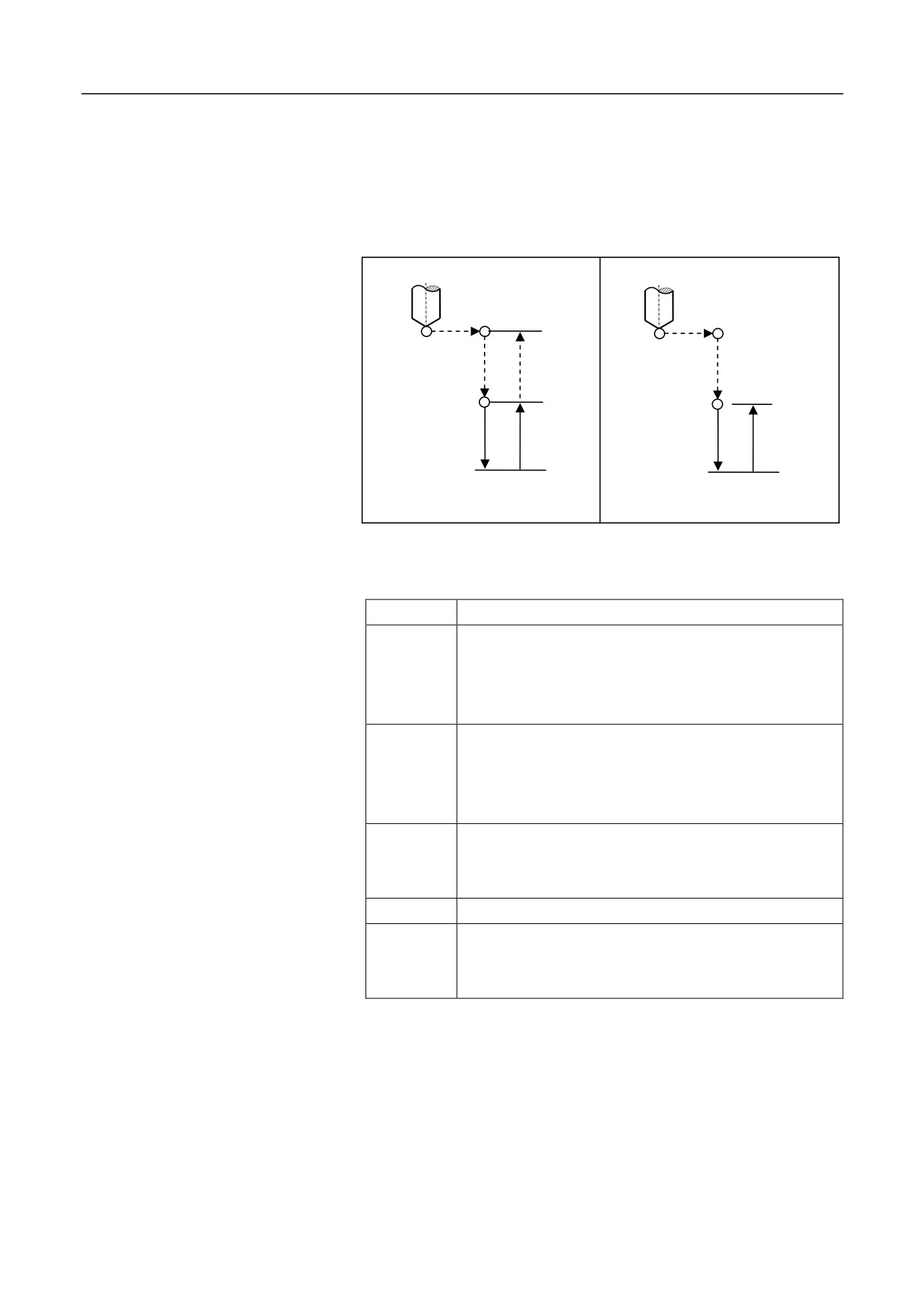
Description
The command is used to bore the holes which have low requirement for
precision. The operation specified by G85 is as shown below:
Initial plane
Plane of point R
Point R
Point R
Point Z
Point Z
G85 (G98)
G85 (G99)
Format
(G98/G99) G85 X_ Y_ Z_ R_ F_ L_;
Parameter
Description
X Y
The absolute position of the hole for absolute
programming (G90), or the distance from the current
tool position to the hole for incremental programming
(G91). UW programming is not supported.
Z
The absolute position of the hole bottom for absolute
programming (G90), or the distance from the hole
bottom to the point R for incremental programming
(G91).
R
The absolute position of the point R for absolute
programming (G90), or the distance from the point R to
the initial plane for incremental programming (G91).
F
Cutting feed speed.
L
The repeat count (Generally used for multi-hole
machining to simplify programming. It is optional when
L=1.)
Operation procedure
1. The tool moves rapidly to the point B over the hole center.
2. Move rapidly to the point R, close to the workpiece.
182