HNC-818. User Manual - page 4
9. Coordinate Values and Dimension Unit
9 Coordinate Values and Dimension Unit
This chapter includes the following sections:
9.1 Absolute Commands and Incremental Commands
9.2 Dimension Unit Selection
9.3 Polar Coordinate Programming (M)
9.4 Diameter and Radius Programming (T)
90
9. Coordinate Values and Dimension Unit
9.1 Absolute Commands and Incremental Commands (G90, G91)
There are two methods to specify tool movement: absolute commands
and incremental commands:
y Absolute commands are used to create programs for the tool
movement end point coordinates.
y Incremental command is used to create programs for the amount of
tool movement.
Format
y Milling Machines
-
Absolute command G90 IP_;
-
Incremental command G91 IP_;
y Turning Machines (two formats):
-
First: Absolute command G90 IP_;
Incremental command G91 IP_;
-
Second: UVW incremental programming
When UVW is not defined as a coordinate axis and the channel
parameter Enable Programming with UVW (040033) is set
to 1, you may use UVW to present the incremental value of
XYZ.
Description
It can simplify programming by selecting a proper programming mode.
When the blueprint dimension is based on a fixed point, it is
recommended to use the absolute programming. When the blueprint
dimension is based on the distance between contour vertexes, it is
recommended to use the incremental programming.
91
9. Coordinate Values and Dimension Unit
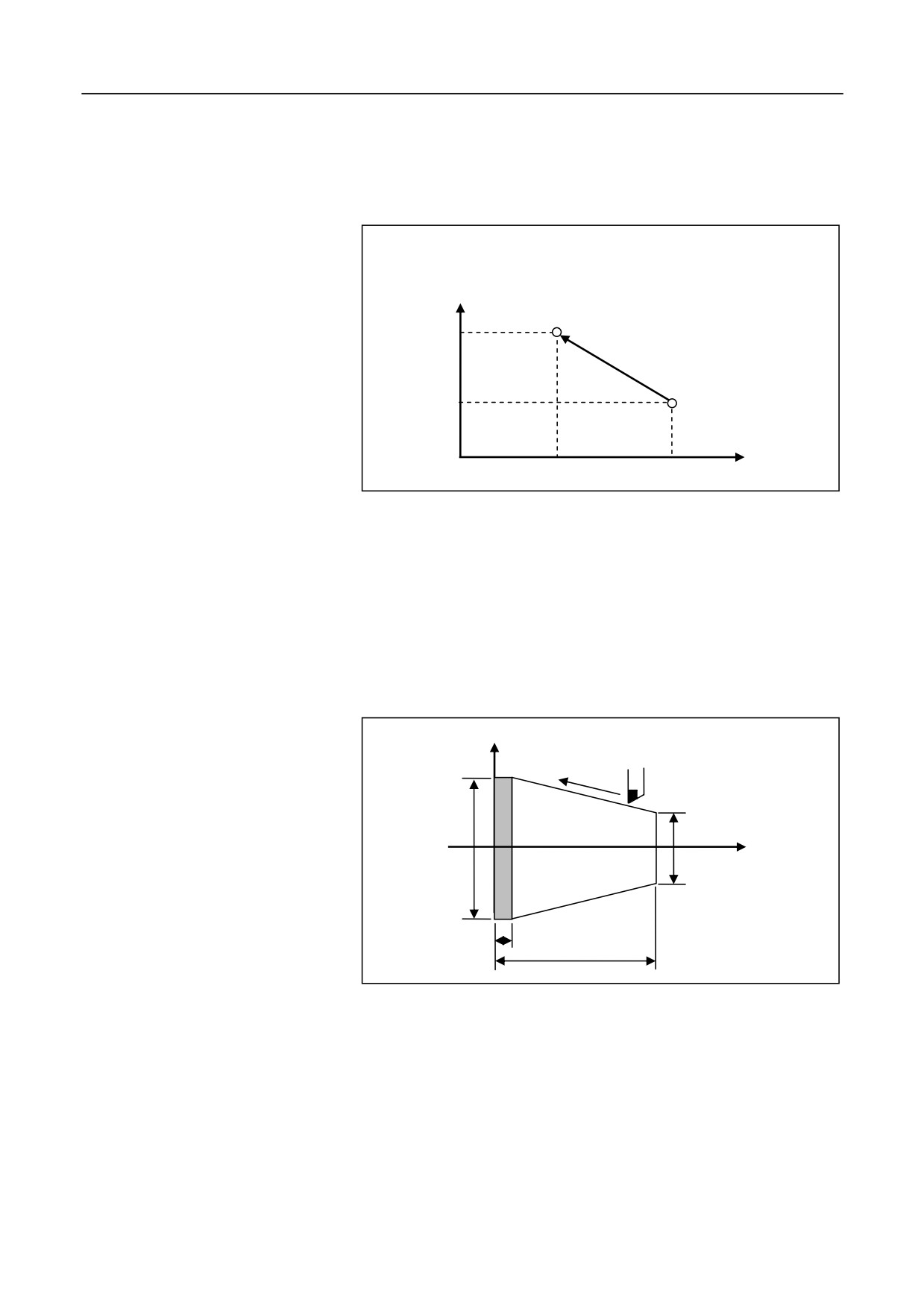
1.
Milling machines
G90 X40.0 Y70.0;
Absolute command
G91 X-60.0 Y40.0;
Incremental command
Y
End point
70.0
Example
30.0
Start point
X
40.0
100.0
2.
Turning machines
The tool moves from P to Q (X axis indicates the diameter value
commands).
Absolute command: G90X400Z50
Incremental command: G91X200Z-400 or U200W-400
X Q (400, 50)
P (200, 450)
ĭ400
ĭ200
Z
50
ĭ450
92
9. Coordinate Values and Dimension Unit
9.2 Dimension Unit Selection (G20, G21)
You may select dimension unit with G20/G21.
Format
G20
Inch input mode
G21
Metric input mode
Description
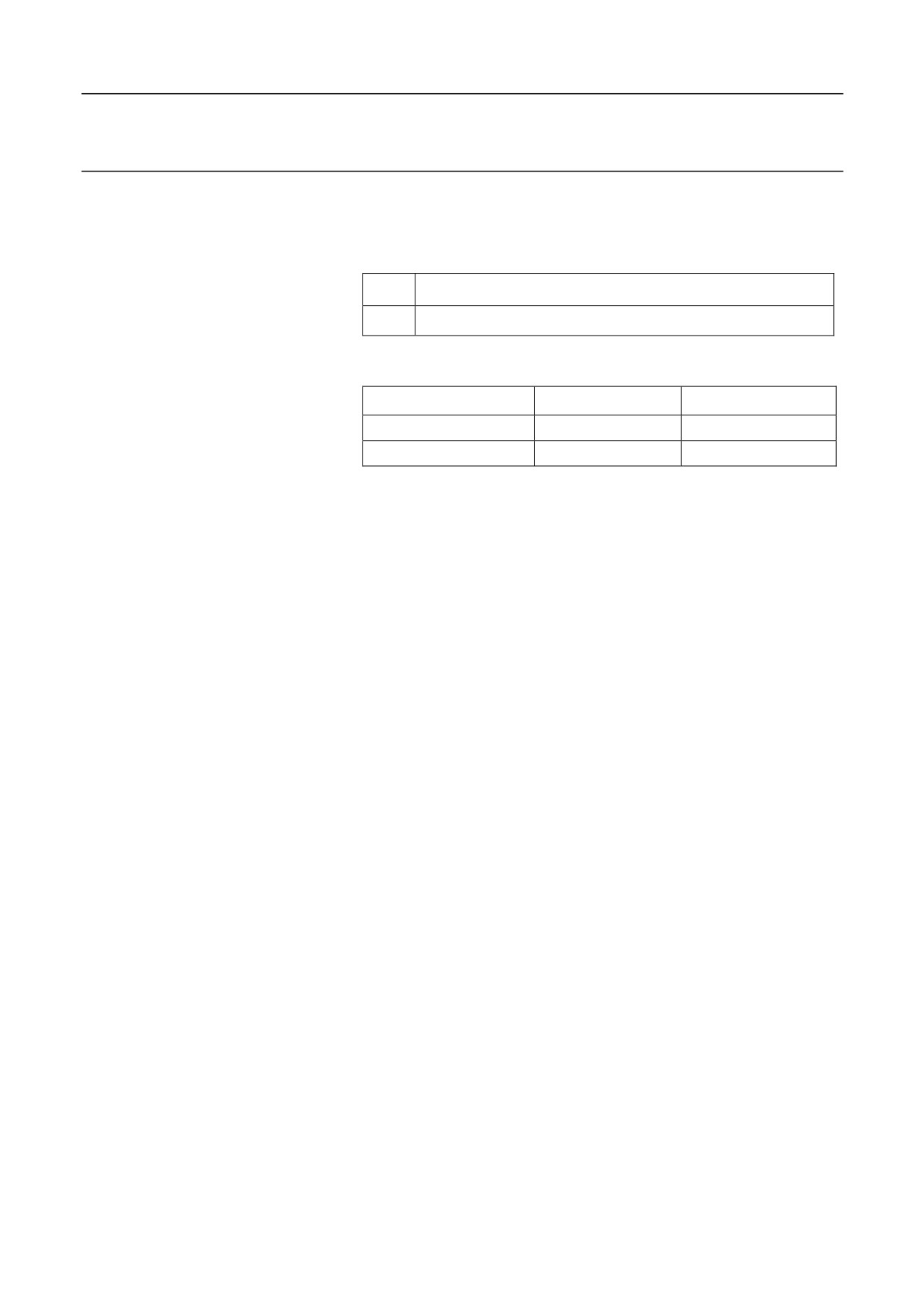
G Code
Linear Axis
Rotation Axis
Inch input (G20)
inch
Degree (deg)
Metric input (G21)
Millimeter (mm)
Degree (deg)
Attention
1.
G20 and G21 are modal functions, which can be canceled by each
other. G21 is the default value after power on.
2.
The unit of the data input for G codes has nothing to do with the
unit of the data displayed on the HMI interface. G20/21 is used to
select the unit of the data input for G codes, but cannot change the
data unit displayed on the HMI interface. The NC parameter SIZE
METRIC/INCH (000025) is used to set the coordinate data unit
displayed on the interface.
Example
%0007
G54
G01 x10y10z10
G20
x2y2z2
M30
93
9. Coordinate Values and Dimension Unit
9.3 Polar Coordinate Programming (M) (G16, G15)
For G code programming, it is more convenient and faster to create
programs by entering the coordinate values of the end point at the polar
coordinate system of the radius and angle.
From the positive direction of the first axis in the specified polar
coordinate plane, the angle in the CCW direction is positive, and the
angle in the CW direction is negative.
The absolute command and incremental command (G90, G91) can be
used to specify radius and angle.
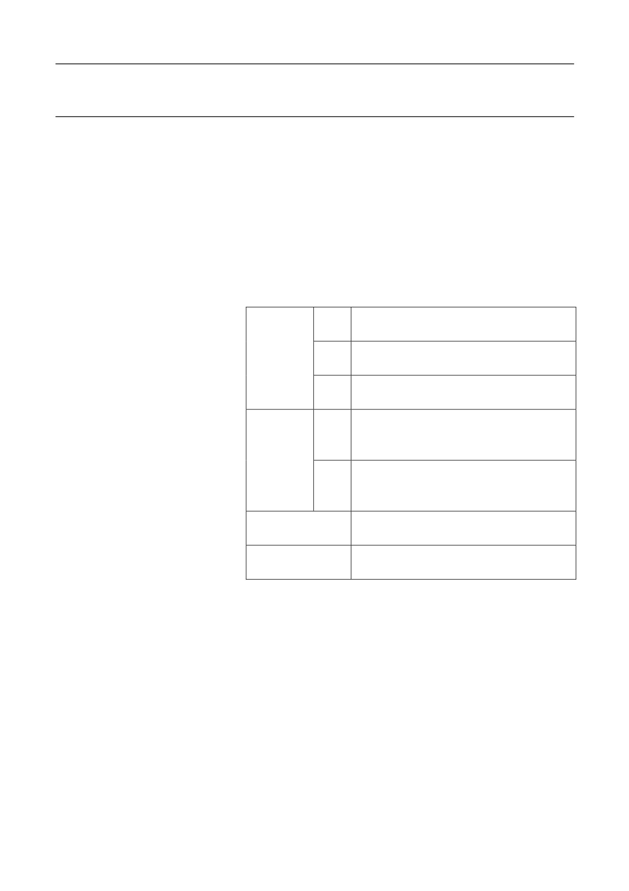
Format
XY plane: The X axis specifies the polar radius
Define the
G17
while the Y axis specifies the polar angle.
plane of the
ZX plane: The Z axis specifies the polar radius
polar
G18
while the X axis specifies the polar angle.
coordinate
YZ plane: The Y axis specifies the polar radius
system
G19
while the Z axis specifies the polar angle
Define the
Specify the workpiece coordinate system origin
origin of the
G90
as the origin of the polar coordinate system,
polar
and measure radius from this point.
coordinate
Specify the current point as the origin of the
system
G91
polar coordinate system, and measure radius
from this point.
G16
Start of the polar coordinate programming
command
G15
End of the polar coordinate programming
command
Set origin of polar coordinate
system
There are two methods to set the origin of the polar coordinate system:
1.
Specify the workpiece coordinate system zero point as the origin of
the polar coordinate system
Specify the radius with absolute value.
Specify the workpiece coordinate system origin as the origin of
the polar coordinate system.
When using the local coordinate system (G52), the origin of the
94
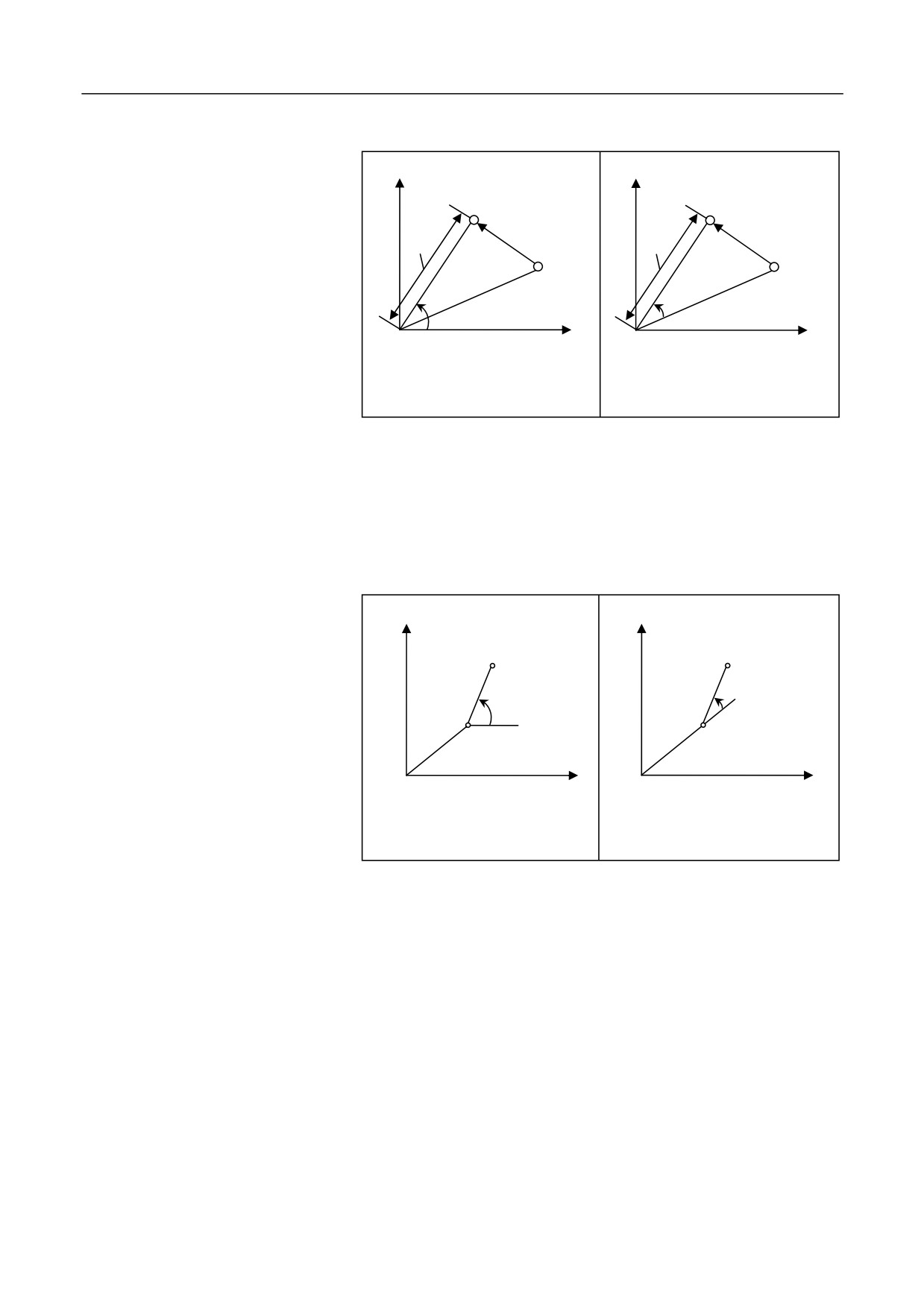
9. Coordinate Values and Dimension Unit
local coordinate system is the
origin of the polar coordinate
system.
Command position
Command position
Radius
Radius
Actual position
Actual position
Angle
Angle
Origin of workpiece coordinate system
Origin of workpiece coordinate system
a) When the angle is specified with an
b) When the angle is specified
absolute command
with an incremental command
2.
Specify the actual position as the origin of the polar coordinate
system
Specify the radius with incremental value.
Specify the actual position as the origin of the polar coordinate
system.
Command position
Command position
Angle
Angle
Actual position
Actual position
Origin of workpiece coordinate system
Origin of workpiece coordinate system
a) When the angle is specified with an
b) When the angle is specified
absolute command
with an incremental command
Attention
1.
The axis command with the following commands will not be
regarded as polar coordinate command:
y Pause G04
y Programmable data input G10
y Local coordinate system G52
y Change workpiece coordinate system G92
y Machine coordinate system selection G53
95
9. Coordinate Values and Dimension Unit
y Coordinate rotation G68
y Scaling G51
2.
In the polar coordinate system, any degrees of angle/convex corner
R cannot be specified.
3.
In the polar coordinate system, you cannot use fixed cycle G
commands.
4.
For polar coordinate programming, when specifying the radius with
absolute values, set the workpiece coordinate system origin as the
polar coordinate system origin; when specifying the radius with
incremental values, set the actual position as the polar coordinate
system origin. However, if only angle is specified in the command,
set the workpiece coordinate system origin as the polar coordinate
system origin both in absolute mode and incremental mode.
Examples
1.
Use absolute commands to specify the radius and angle
%1000;
G54
G00 X0Y0Z0
G17 G90 G16;
G01 X100.0 Y30.0F1500
Y150.0;
Y270.0;
G15
M30
2.
Use absolute command to specify
the
radius
and
incremental
command to specify the angle
%1000
G54
G00 X0Y0Z0
G17 G90 G16;
G01 X100.0 Y30.0F1500
G91Y120.0;
Y120.0;
96
9. Coordinate Values and Dimension Unit
G15
M30
97
9. Coordinate Values and Dimension Unit
9.4 Diameter and Radius Programming (T) (G36, G37)
Format
G36; Diameter programming
G37; Radius programming
Description
The shape of the workpiece to be processed in a turning machine is
usually a rotating piece, and its X axis dimension can be specified in two
ways: diameter and radius modes. G36, the default value, indicates the
diameter programming.
Attention
1.
The Z-axis command input has nothing to do with the diameter or
radius programming.
2.
When G02 or G03 is specified, the parameter values of R, I, K are
radius values.
3.
In single fixed rotation, the parameter R used as the tool feed along
the X axis indicates the radius value.
4.
For turning machines or machining center, the default mode is the
diameter programming (G36).
5.
Specify the axial feed rate based on the change of radius.
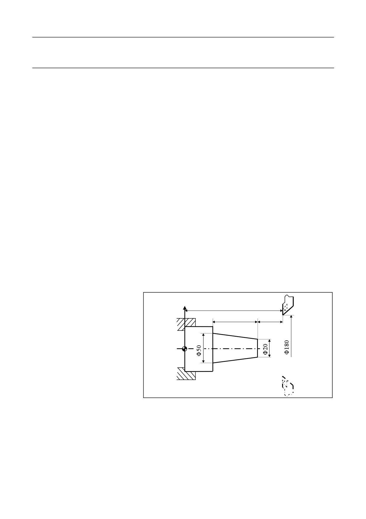
Example
254
+X
160
44
98
9. Coordinate Values and Dimension Unit
Diameter programming
Radius programming
%3341
%3342
N1 G92 X180 Z254
N1 G92 X90 Z254
N2 G36 G01 X20 W-44
N2 G37 G01 X10 W-44
N3 U30 Z50
N3 U15 Z50
N4 G00 X180 Z254
N4 G00 X90 Z254
N5 M30
N5 M30
99
10. Tool Compensation Function
10 Tool Compensation Functions
This chapter includes the following sections:
10.1 Tool Offset (T)
10.2 Tool Nose Radius Compensation (T)
10.3 Introduction to Tool Radius Compensation (M)
10.4 Detailed Description of Tool Radius Compensation (M)
10.5 Tool Length Compensation (M)
100
10. Tool Compensation Functions
10.1 Tool Offset (T)
The programming path is the motion path of the tool nose. However, in
real machining, the geometry dimensions and installation positions of
different tools are different; therefore, the relative position of the tool
nose to the center of the turret is different. You need to measure and set
the tool nose position, so that the system may conduct tool offset
compensation during the machining. When programming, you do not
need to take into account the tool nose position difference caused by tool
shape and installation position.
Tool dimension error may be caused by tool wear after a period of usage;
therefore the compensation is required. The compensation and tool offset
compensation are stored in the same register address number. The tool
wear compensation of a tool is only valid for the tool (including the
standard tool).
10.1.1 T Command for Tool Offset
The tool compensation is specified by T commands, and the four digits
after T express selected tool number and tool offset compensation (for
details, see section 4.3).
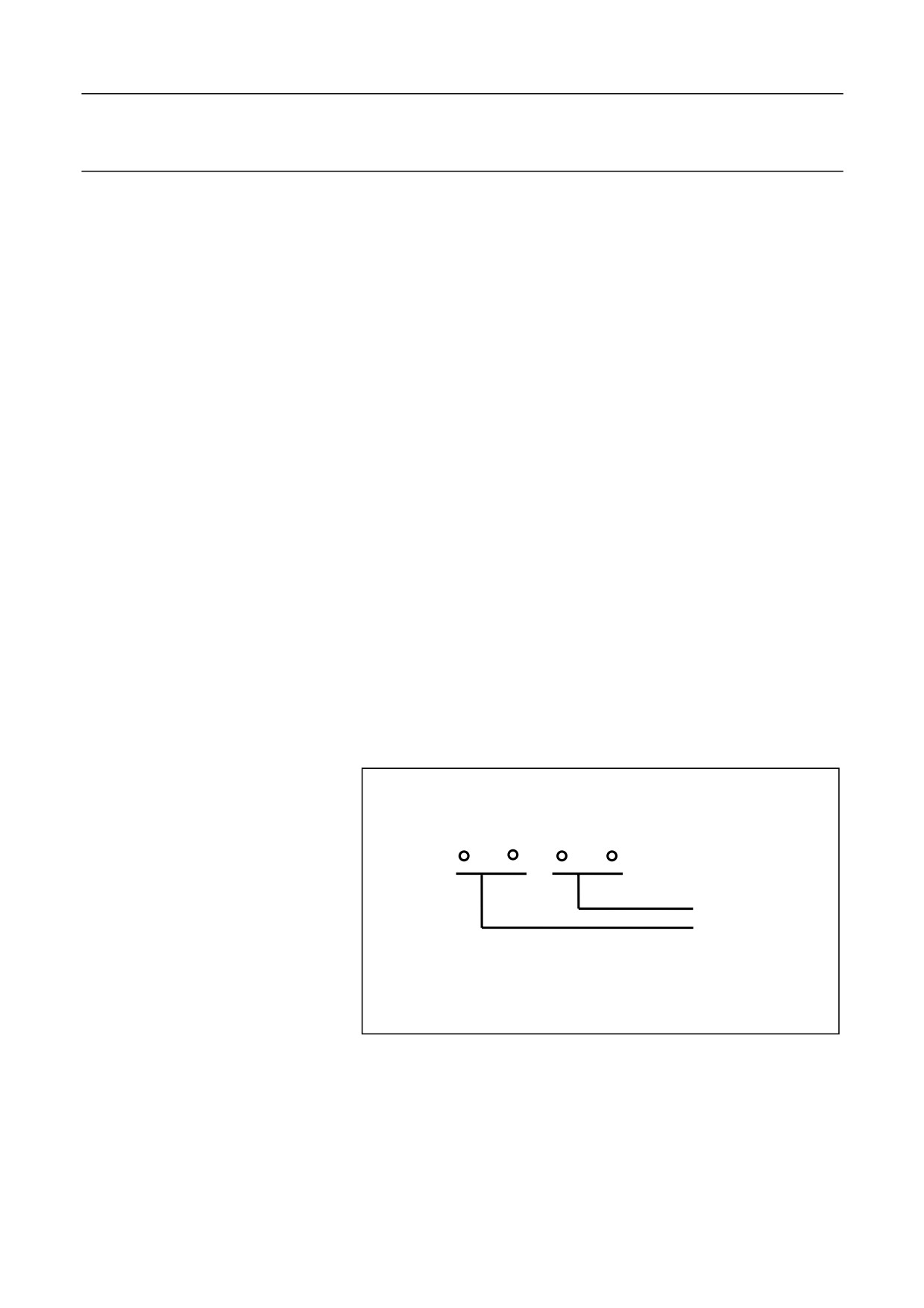
The description of T command is as follows:
T
Tool geometry offset
number
Tool number
The tool offset number is the address number of the tool offset
compensation register which stores the tool offset compensation values
and tool wear compensation value of X axis and Z axis.
T plus compensation number starts the offset compensation feature. The
offset number 00 expresses the offset is 0. In this case, the offset feature
101

10. Tool Compensation Functions
is canceled.
The tool geometry offset number and tool number may be the same or
different. In other words, multiple tool offset numbers
(value) may
correspond to one tool.
Example
N1 G00X100Z140
N2 T0313 (select No. 3 tool and the tool offset of No. 13 tool)
N3 X200Z150
As shown in the figure below, if there is compensation value for the tool
path (relative to the programming path) in the X, Z axis (the vector of the
compensation in the X, Z direction is referred to as compensation vector),
the position of the end point in the program segment plus or minus
compensation amount
(compensation vector) is the end position
specified by the T command.
Compensation path
Compensation vector
(components in X and Z
axis directions)
Programming path
Program block containing T
commands
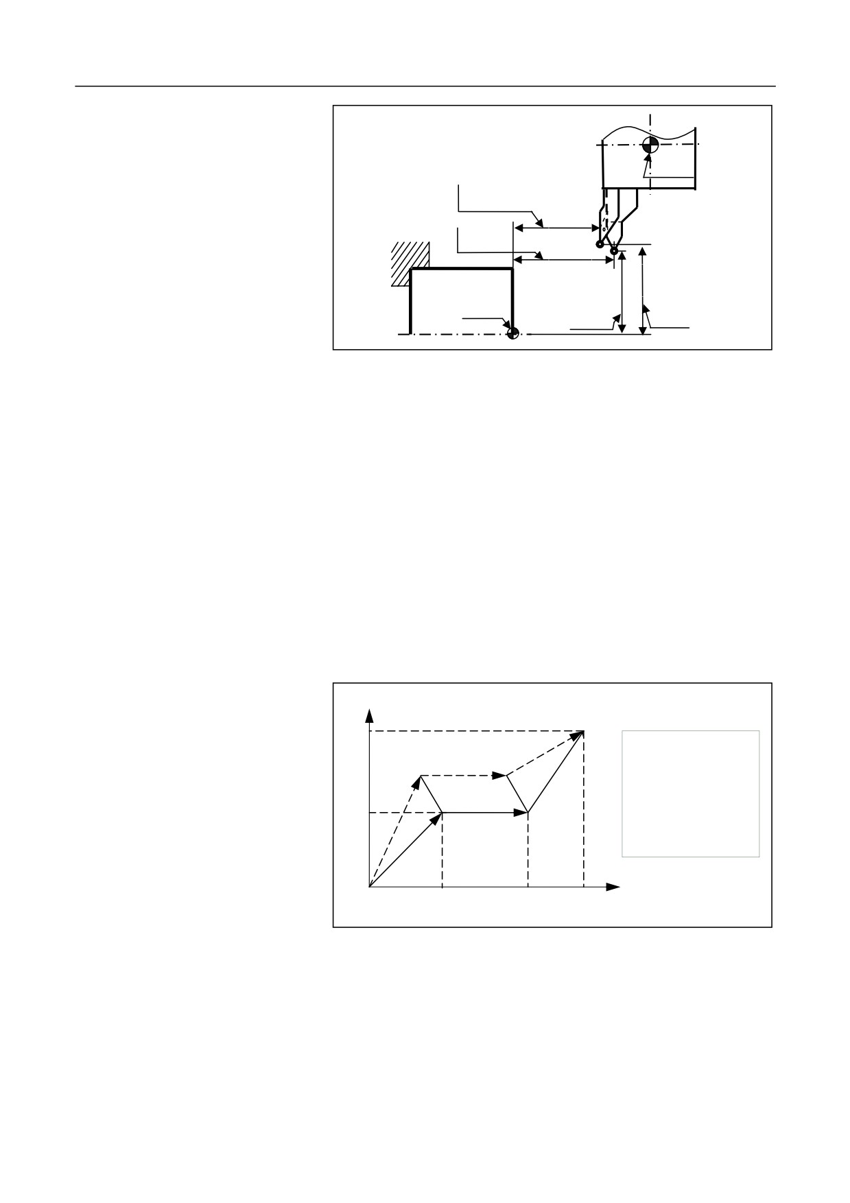
10.1.2 Tool Offset Compensation and Tool Wear Compensation
The programming path of the turning machine is actually the movement
path of the tool nose. But in the actual situation, the geometry dimension
and installation position of different tools are different, and the relative
position of the tool nose to the center of the turret is different. Hence,
you need to measure and define the tool nose position of each tool, so
that the system may conduct tool offset compensation during the
processing. This way, you do not need to take account of the tool nose
position difference caused by the difference of tool shape and installation
position in programming.
102
10. Tool Compensation Functions
Machine origin
No. 1 tool Z
Absolute Compensation Mode
axis offset
Z1
No. 2 tool Z
axis offset
Z2
X
2/2
X1/2
No. 2 tool X
Workpiece origin
axis offset
The absolute tool offset indicates the orientation distance from the tool
nose of each tool on the turret to the workpiece zero when the machine
returns to the machine zero. When executing tool offset compensation,
the processing coordinate system of each tool is defined based on the
distance. This way, when the turret is at the machine zero, even the tool
dimension and the distance from the tool position to the workpiece zero
are different, the defined coordinate system of each tool is coincide with
the workpiece coordinate system (programmed).
Example
As shown in the figure below, set tool offset wear compensation, and
then cancel the tool offset wear compensation:
X
100
T0202
Tool compensation path
G01 X50 Z100
Z200
50
X100 Z250 T0200
Programming path
M30
Z
100
200
250
103
10. Tool Compensation Functions
10.2
Tool Nose Radius Compensation (T) (G40, G41, G42)
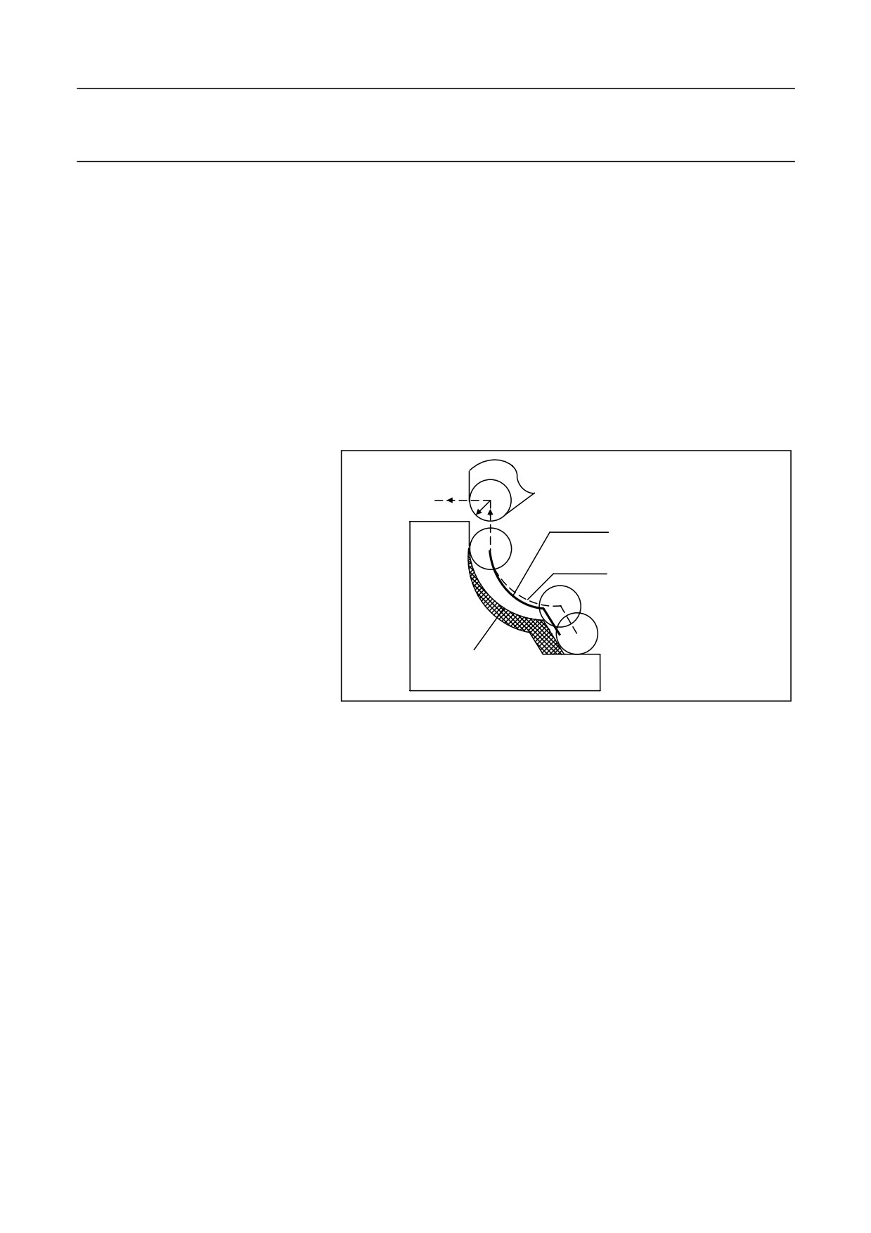
The CNC program is generally created based on the dimension of the
workpiece for a point that is on the cutting tools (cutter location point),
which is generally the imaginary tool nose
(point A) under ideal
conditions or the center point of the tool nose circle (O). But in the actual
processing, the tool nose may not be a point but an arc because of the
processing craft or other requirements. During cutting, the cutting point
changes on the arc. This way, there may be deviation between the actual
cutting position and the cutter location point, and thereby causing
excessive or less cutting. The processing error, caused because that the
tool nose is not an ideal point but one arc, can be eliminated by the nose
radius compensation function.
Tool nose
R
Tool path without compensation
Tool path with compensation
Workpiece
Cutting depth without tool nose radius compensation
Attention
Radius compensation does not support interruption command such as
G31.
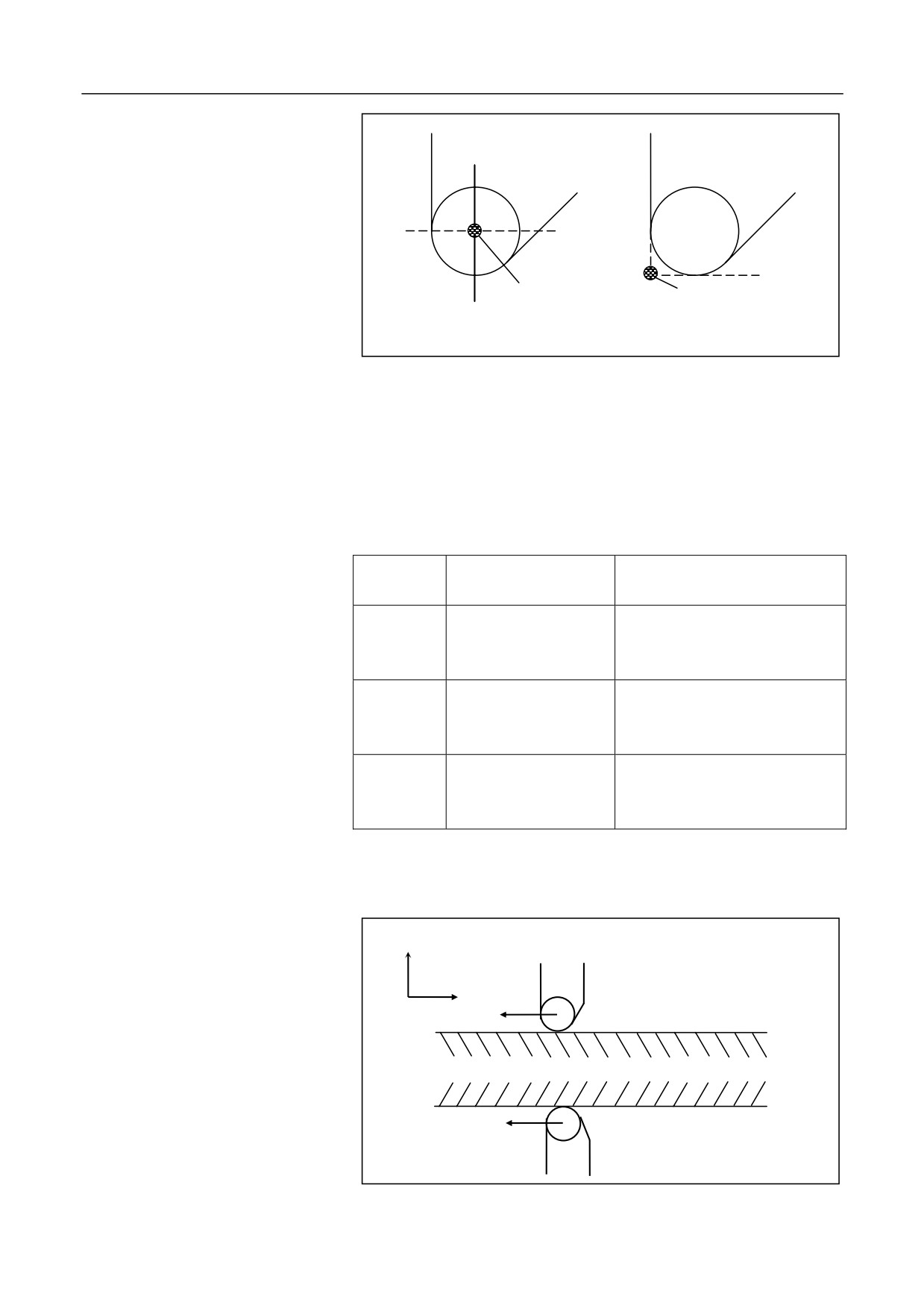
10.2.1 Imaginary Tool Nose
As shown in the figure below, the imaginary tool nose point (A) does not
exist. It is more difficult to set the radius center of actual tool nose at the
start point than to set the imaginary tool nose at the start point. Hence,
the imaginary is necessary.
When using the imaginary tool nose, you do not need to consider the
radius of tool nose during programming.
When the tool is set at the start point, the position is as below:
104
10. Tool Compensation Functions
Start point
Start point
Programming based on the
Programming based on the
tool nose center
imaginary tool nose
Description
The tool nose arc radius compensation function can be used to add or
cancel radius compensation, which is specified with the G41/G42/G40
and too nose radius compensation number specified by T.
Format
G Code
Workpiece Position
Tool Path
G40
Canceling tool nose
Move along the tool path
radius compensation
G41
Left tool compensation
Compensation at the left side of
the tool movement direction
G42
Right tool
Compensation at the right side
compensation
of the tool movement direction
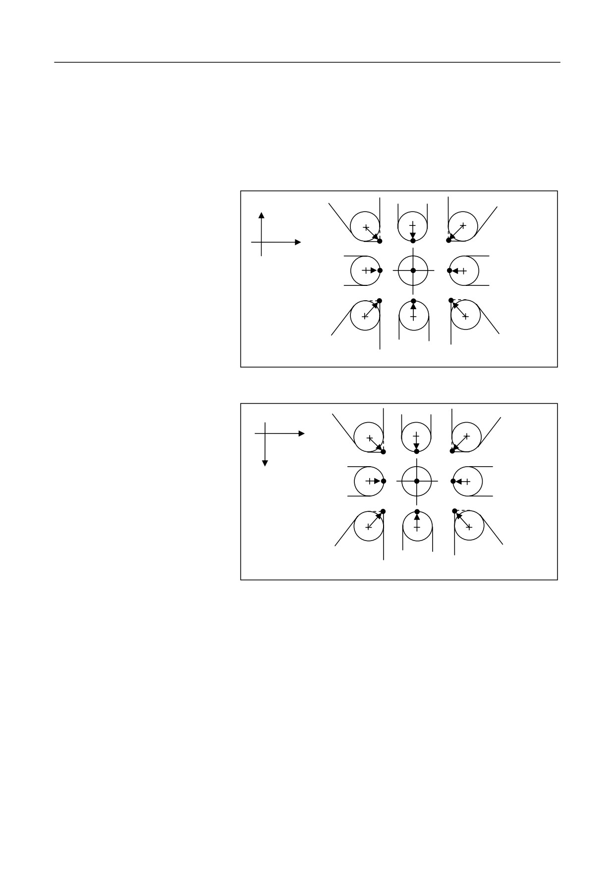
See the figure below:
X
G42: tool on the right of its
movement direction
Z
G41:too on the left of its
movement direction
105
10. Tool Compensation Functions
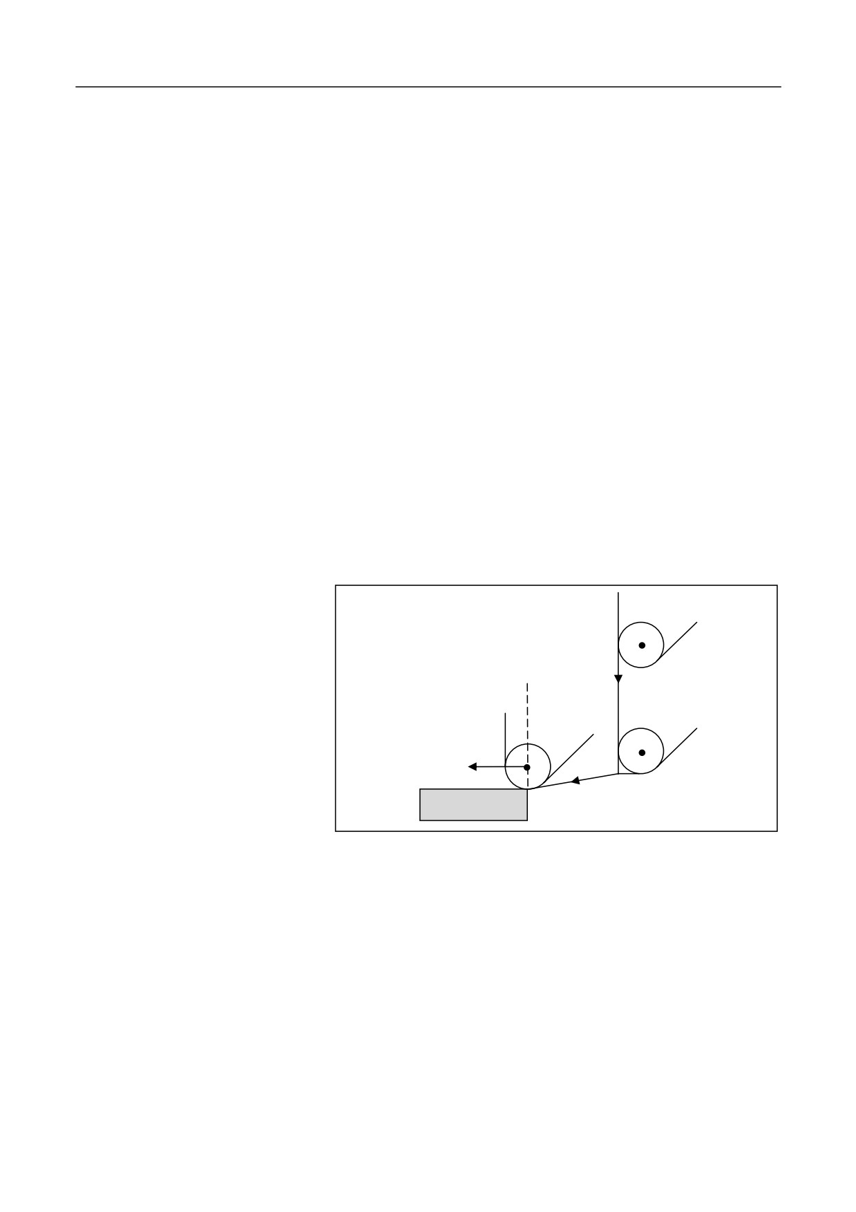
10.2.2 Define Tool Nose Direction
The direction number of cutting tool nose defines the relationship
between the cutter location point and tool nose center. There are ten
directions ranging from 0 to 9. See the figure below:
Back tool turret
X
4
8
3
Z
0
9
5
7
1
6
2
"Ɣ": Cutter location point A, "+": Tool nose circle center O
Front tool turret
1
6
2
Z
X
0
9
5
7
4
8
3
"Ɣ": Cutter location point A, "+": Tool nose circle center O
106
10. Tool Compensation Functions
Attention
1.
G40, G41, and G42 are modal codes, which can be canceled by
each other.
2.
G41/G42 is not followed by any parameters, and its compensation
number
(indicating the tool nose radius compensation
corresponding to the tool) is specified by T commands. The tool
nose arc compensation number corresponds to the tool offset
compensation number.
3.
The command used to establish or cancel the tool radius
compensation can be only G00 or G01, but cannot be G02 or G03.
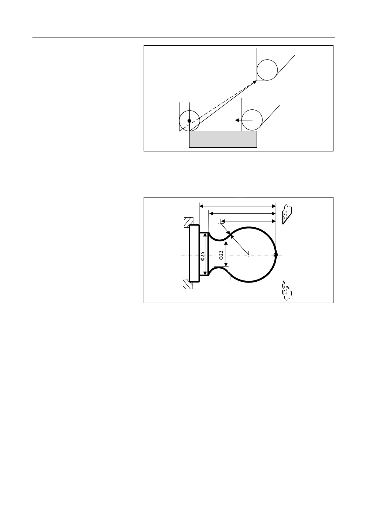
Tool Offset Transition
The program block changing from G40 to G41 or G42 is called the
program of tool offset transition.
G40_;
G41_; (starting cutting)
The tool offset transition movement is performed in this program block.
In the start point of the next program block after it, the tool nose center is
located in the vertical line of the programming path.
G40
G42
Workpiece
G42 (Start)
The program block changing from G41 or G42 to G40 is called the offset
Cancel Offset
cancelation program.
G41_;
G40_; (offset cancelation program)
In the program block prior to the offset cancelation program, the tool
nose center moves to the position vertical to the programming path. The
tool is located at the end point of the offset cancelation program. See the
figure below:
107
10. Tool Compensation Functions
End point
G40
G42
Workpiece
Example
Create a program for the workpiece machining as shown in the figure
below (considering the tool radius compensation):
40
31
27
R5
R15
%3323
N1 T0101 (change to the No. 1 tool and set the coordinate system)
N2 M03 S400 (CW rotate spindle at 400r/min)
N3 G00 X40 Z5 (move to the program start point)
N4 G00 X0 (the tool moves to the workpiece center)
N5 G01 G42 Z0 F60 (add tool radius compensation, and move to the
workpiece position)
N6 G03 U24 W-24 R15 (process the R15 arc segment)
N7 G02 X26 Z-31 R5 (process the R5 arc segment)
N8 G01 Z-40 (process the ĭ26 external circle)
N9 G00 X30 (exit the processed surface)
N10 G40 X40 Z5 (cancel the radius compensation, and return to
108
10. Tool Compensation Functions
the program start point)
N11 M30 (stop spindle, end the main program and reset)
109
10. Tool Compensation Functions
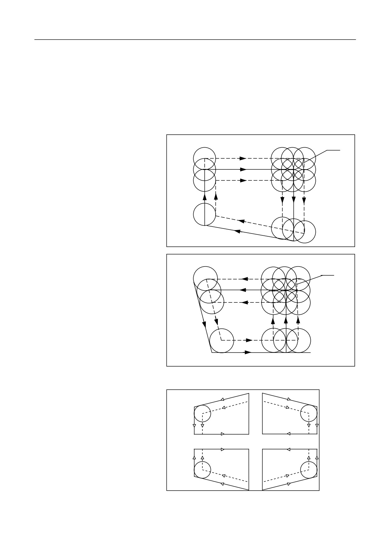
10.2.3 Usage of Tool Radius Compensation
Tool nose radius compensation of
1.
Movement path in the direction of the imaginary tool
inner/outer diameter cutting cycle
The tool movement path direction is generally parallel to the
(G80) or end-face cutting cycle
programming path. The figure below shows the paths with tool nose
(G81)
radius compensation in nine tool nose directions:
G80 tool path center
8
0
4
3
5
7
1
2
6
Start point
Programming path
G81 tool path center
8
4
3
0
5
7
1
2
6
Start point
Programming path
2.
Offset direction
G80
110
10. Tool Compensation Functions
G81
Tool nose radius compensation of
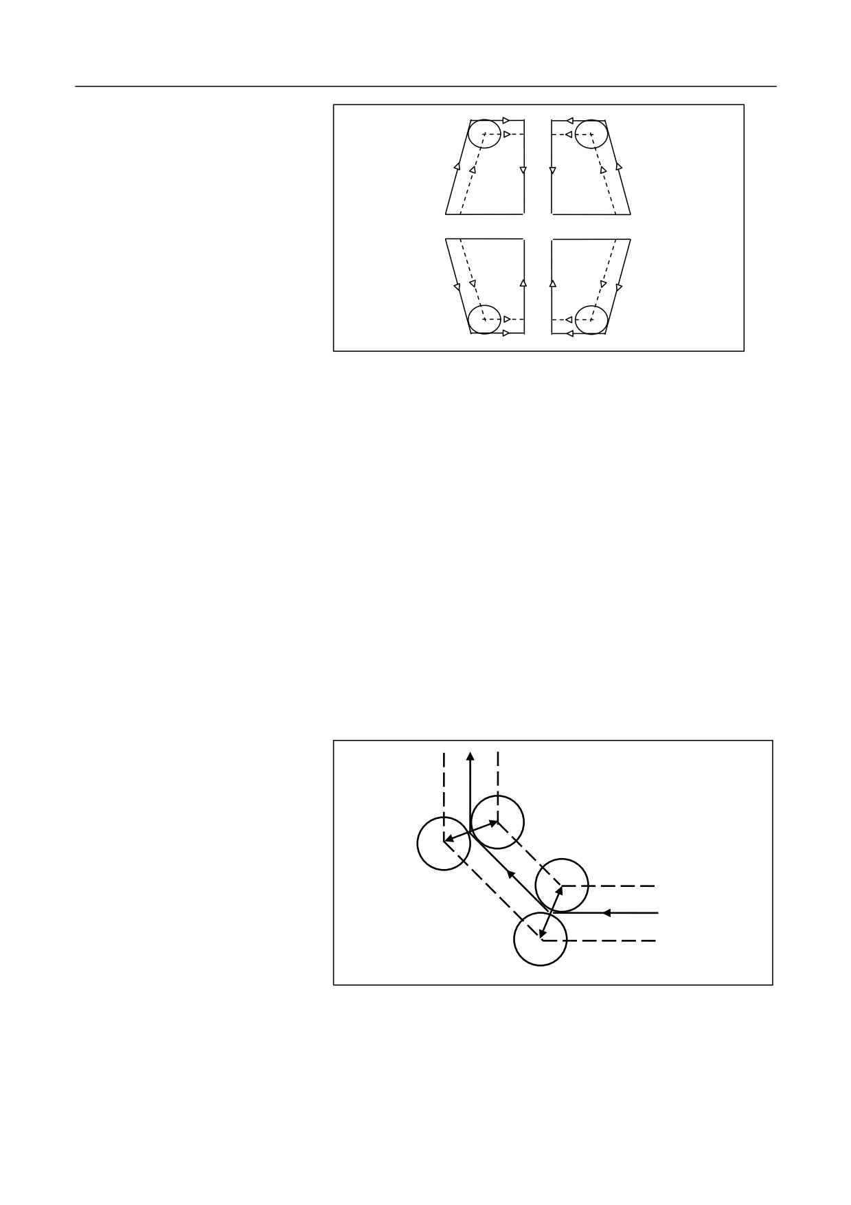
When you specify the following cutting cycle, the tool offset will be a
cutting cycle
tool nose radius compensation vector, without intersection calculation
during the cycle.
Note: The establishment and cancelation of radius compensation must be
between the P/Q segments of the combined cycle.
y G71 Inner (outer) diameter rough-turning compound cycle
y G72 End-face rough-turning compound cycle
y G73 Closed turning compound cycle
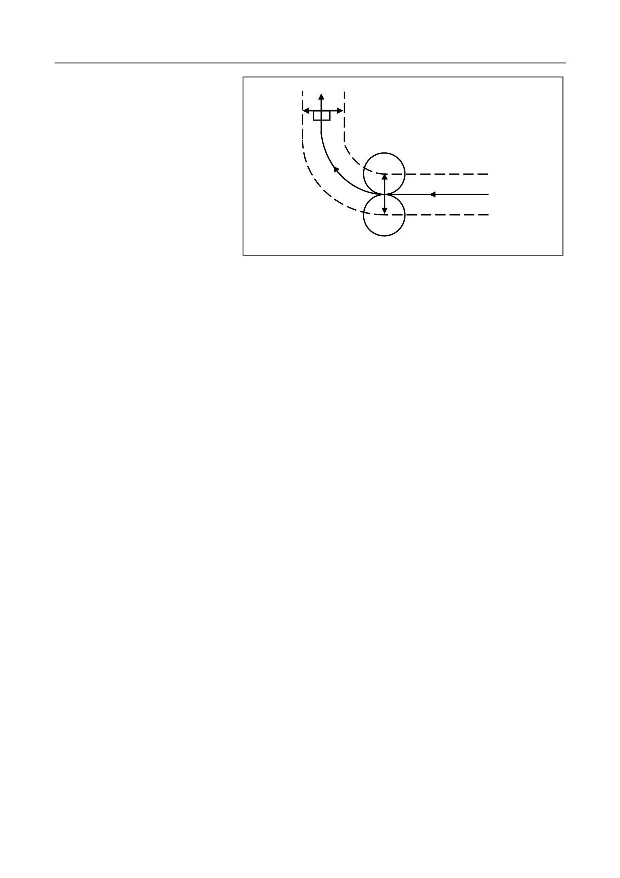
Tool nose radius compensation of
The figure below shows the compensation motion:
chamfer
(G42)
Programming path
(G41)
111
10. Tool Compensation Functions
Tool nose radius compensation of
corner arc
(G42)
Programming path
(G41)
112
10. Tool Compensation Functions
10.3 Introduction to Tool Radius Compensation (M) (G40, G41, G42)
Attention
Radius compensation does not support interruption command such as
G31.
In the program block between G41/G42 and G40, G0 automatically
changes to G01.
10.3.1 Tool Radius Compensation for Milling Machines
During programming, only the tool center path is generally programmed
(the tool radius is assumed as 0). However, in the actual machining, you
need to conduct offset for the tool center path because the tool radius is
not zero (The offset distance equals to the tool radius and the offset
direction may be left or right based on the actual programming). In this
case, tool radius compensation function is required.
Format
G17 (or G18/G19) G41 (or G42) G00 (or G01) IP_ D_;
Attention
1.
Tool radius compensation does not support radius change.
2.
Tool radius compensation does not support the status change of
G41/G42.
Establish Tool Compensation
G17/G18/G19: Define the compensation plane, XY, YZ, ZX plane
respectively
G41/G42: Tool radius compensation is valid. G41: left compensation.
G42: Right compensation.
D: Define the tool radius compensation number.
Cancel Tool Radius Compensation
G40 IP_;
G40: Cancel tool radius compensation (G40, G41, G42 are modal codes,
which can be canceled by each other.)
IP_: The command value of axis movement
113
10. Tool Compensation Functions
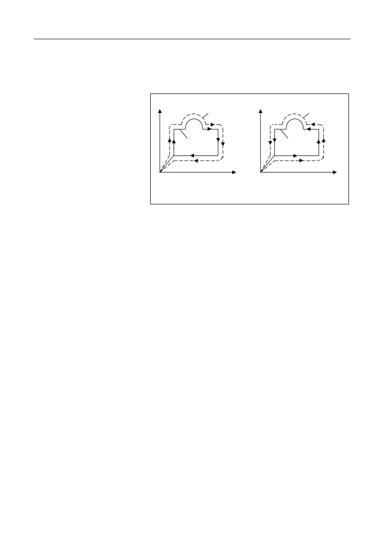
The tool radius compensation function is defined by G41or G42.
G41: Conduct left offset along the tool movement (see a)
Offset Direction
G42: Conduct right offset along the tool movement (see b)
Tool compensation path
Tool compensation path
Programming
Programming
path
path
a: left tool
b: right tool
compensation
compensation
10.3.2 Establish or Cancel Tool Compensation
Establish or cancel radius compensation through G00 or G01.
If the arc interpolation commands (G02, G03) are used to establish or
cancel the tool compensation, an alarm will be reported.
10.3.3 Define Tool Radius Compensation Amount
You may use the D codes to set the tool radius compensation amount by
defining the number of tool radius compensation amount.
The D code is valid until another D code is defined.
Attention
The change of tool radius compensation amount is generally conducted
during tool change when the tool compensation is canceled.
10.3.4 Plane Selection and Vector
114
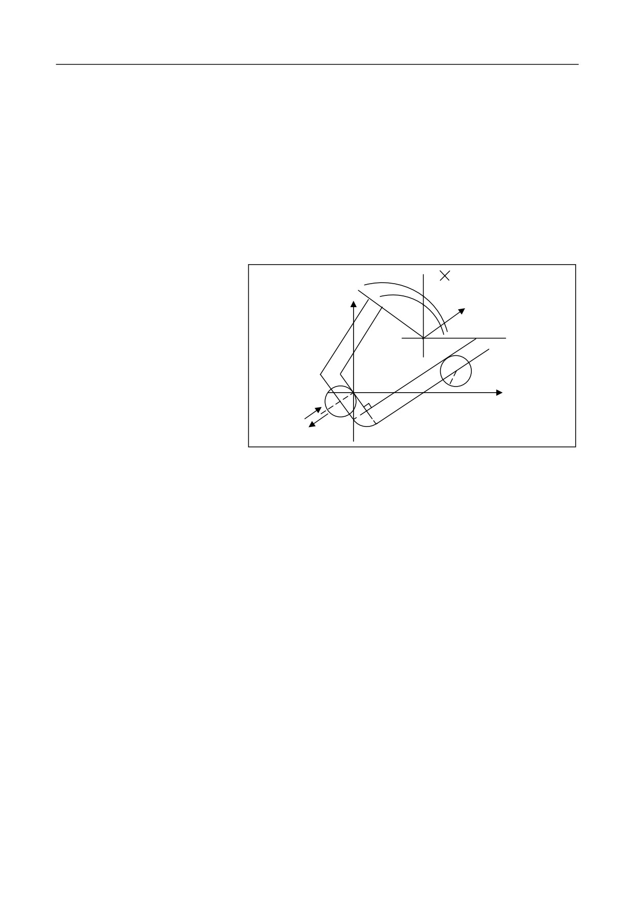
10. Tool Compensation Functions
The offset calculation is based on the
plane defined by G17, G18, and G19.
The plane for offset calculation is
called the offset plane.
The coordinate value on the axis
outside the offset plane is not
Change the offset plane in the offset cancelation mode. An alarm will be
affected by the offset, and can be
reported and the tool stops if the offset plane is changed in the offset
used as originally.
In
the
mode.
simultaneous 3-axis control, the tool
moves in the offset mode based on
the shape
projected
on
the
offset
P3’
plane.
P3
R
P5
P4
P4’
P2
P2’
r
Example
P0
P0’
P
1
P1’’
P1’
%0504
N01 G92 X0 Y0
N02 G0 X-40 Y-26.66
N03 G90 G41 G0 X0 Y0 D3
N04 G1 X-20 Y30 F2000
N05 G1 X43.135529 Y156.271057
N06 G2 X175.554 Y73.70 R80
N07 G1 X20 Y-30
N08 G1 X0 Y0
N09 G40 G0 X-40 Y-26.66
N10 M30
115
10. Tool Compensation Functions
116
10. Tool Compensation Functions
10.4 Description of Tool Radius Compensation (M) (G40, G41, G42)
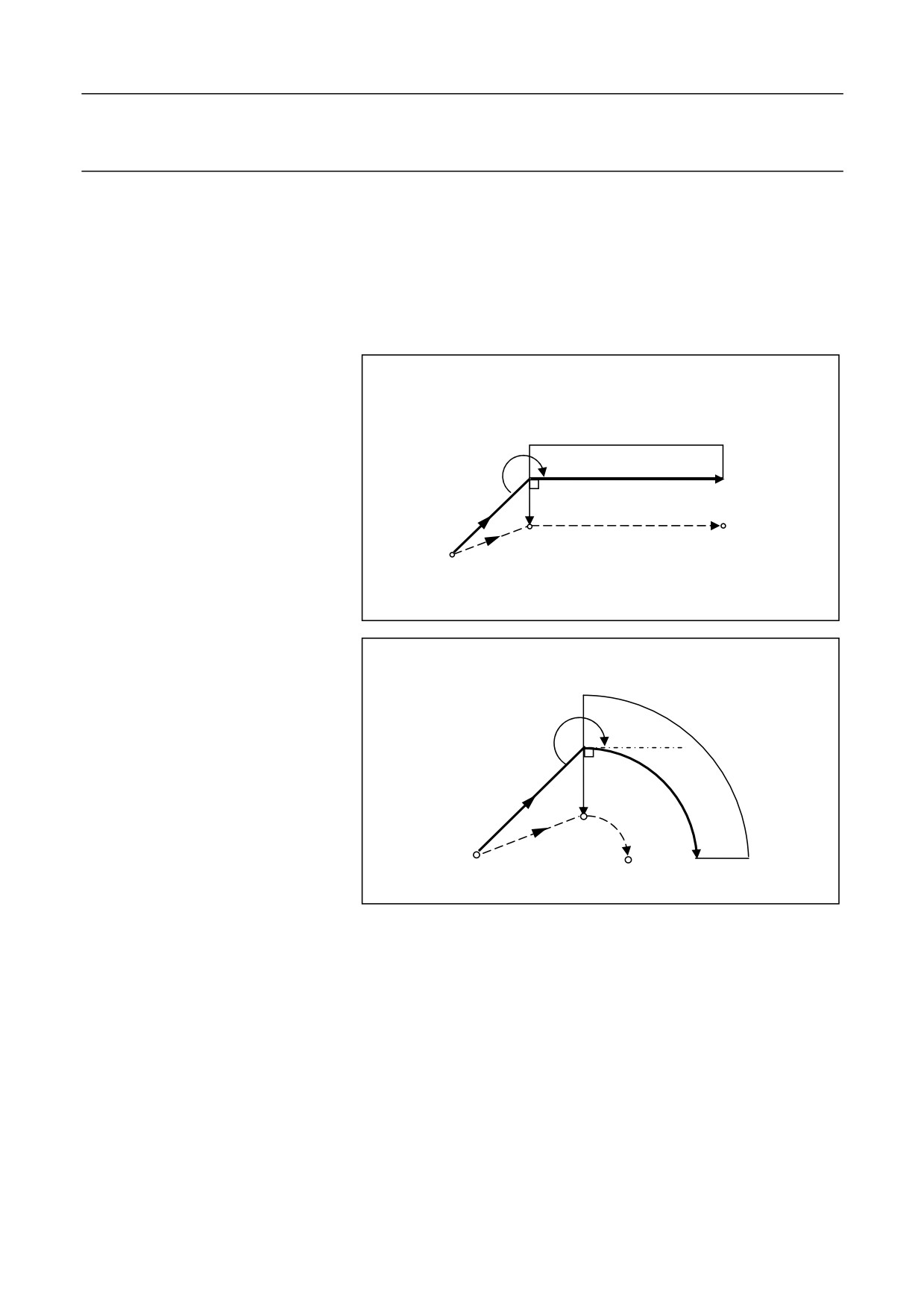
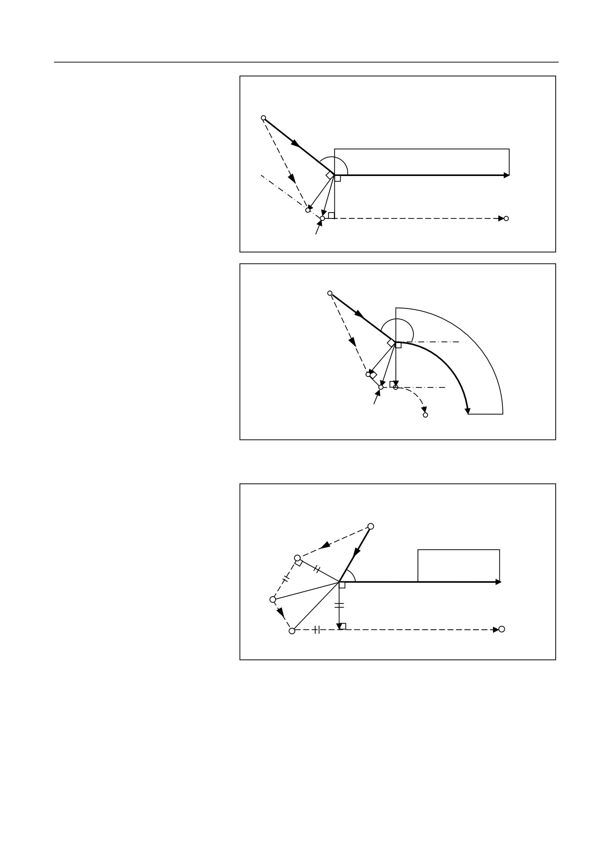
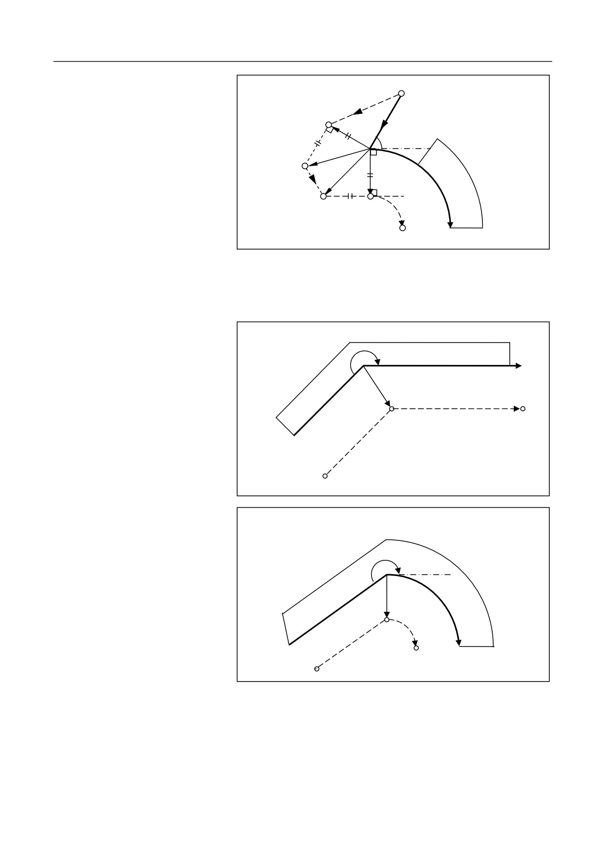
10.4.1 Tool Movement during Tool Start
The figure below shows the tool movement when the mode is changed
from the offset cancelation into the offset mode:
Tool movement around the inner
corner
Linearĺ Linear
(Į180 degrees)
Į
Workpiece
Programming path
G42
r
S
L
Start point
Tool center path
L
Linear ĺ Circular
Į
Workpiece
G42
r
S
C
L
Start point
Tool center path
Programming path
117
10. Tool Compensation Functions
Tool movement around the outer
Linear ĺ Linear
corner
Start point
(90 degrees Į<180 degrees)
G42
Į
Workpiece
L
r
Programming path
r
S
L
Intersection point
L
Tool center path
Linear ĺ Circular
Start point
G42
Į
L
r
Workpiece
r
S
L
L
C
Intersection point
Tool center path
Programming path
Tool movement around the outer
Linear ĺ Linear
corner
Start point
(Į<90 degrees)
L
S
G42
Workpiece
r
Į
L
Programming path
r
L
Tool center path
L
L
118
10. Tool Compensation Functions
Linear ĺ Circular
Start point
L
S
G42
r
Į
L
r
Workpiece
L
L
C
Tool center path
Programming path
10.4.2 Tool Movement in Offset
Tool movement around the inner
Linear ĺ Linear
corner
Į
Workpiece
(Į180 degrees)
Programming path
S
L
Tool center path
Intersection point
L
Linear ĺ Circular
Start point
Į
Workpiece
Intersection
point
C
S
L
Tool center path
Programming path
119
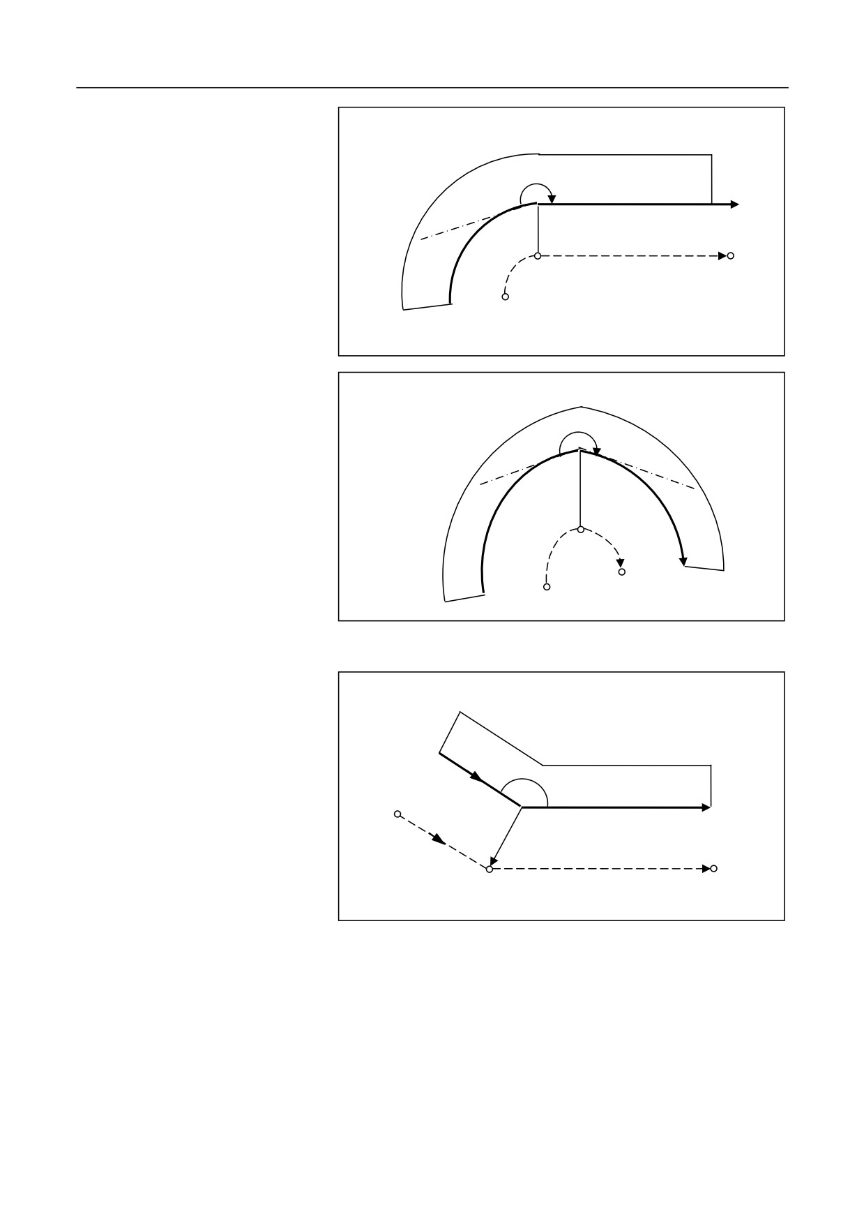
10. Tool Compensation Functions
Circular ĺ Linear
Į
Workpiece
Programming path
S
L
C
Intersection
Tool center path
point
Circular ĺ Circular
Į
Workpiece
Intersection
point
S
C
C
Programming path
Tool center path
Tool movement around the outer
Linear ĺ Linear
corner
(90 degrees Į<180 degrees)
Į
Workpiece
L
Programming path
S
L
Intersection point
Tool center path
120