HNC-818. User Manual - page 3
5. Interpolation Functions
%0001
G54G0X0Y0Z0
G90G17 F1000G64
X0.005y-0.987z0.04
HSPLINE P3 X0.005 Y-0.987 Z0.040 I1.000 J-0.026 K-0.002; Q1
X0.748 Y-0.727 Z0.027 I0.756 J0.655 K-0.016; Q2
X1.049 Y-1.097 Z0.023 I0.967 J0.256 K-0.011; Q3
X1.249 Y-0.727 Z0.053 I0.497 J0.866 K0.050; Q4
M30
59
5. Interpolation Functions
5.8 GOTO Function (G31)
G31 is followed by axes, the motion path of which is similar to the G01
linear interpolation. When G31 command is executed, if an external
GOTO signal is input, the execution will be interrupted and the system
proceeds to execute the next block instead.
You may use the GOTO function if the processing end point is not
specified in the program, but specified with the signal from the machine,
e.g. grinding. The GOTO function can also be used to measure the
dimension of the workpiece.
Format
G31 L_IP_; The number behind L indicates the trigger point number,
which must be the same as that in PLC.
G31: non-modal G-code
Description
The coordinate values when the GOTO signal is connected can be used
in user macro-program because they are stored in the axis macro
variables of user macro programs. The axis macro variables start from
60000, and each axis uses 100 macro variables. For example, if the X
axis number is 0, the X-axis variables start from 60000 to 60099; if the Y
axis number is 1, the Y-axis macro variables starts from 60100 to 60199;
similarly, the Z axis macro variables start from 60200 to 60299. Macro
variables related to measurement are defined as follows:
#60010-60011: The command position of the axis 0 on the machine
when receiving measurement signals
#60012-60013: The real position of the axis 0 on the machine when
receiving measurement signals
#60014-60015: The position of the No.2 encoder on the axis 0 when
receiving measurement signals
#60016: The speed on the axis 0 when receiving measurement signals
#60017: The current of the axis 0 when receiving measurement signals
Example
If there is a X7.6 signal, then go to the next block.
60
5. Interpolation Functions
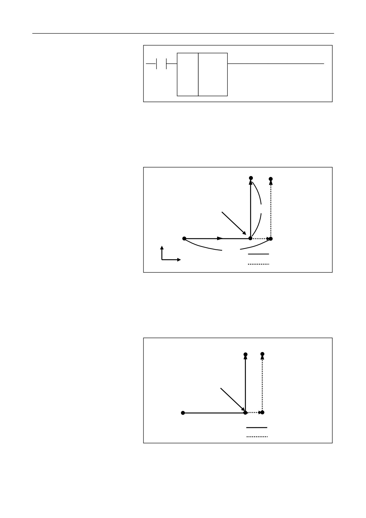
X7.6
ESC
0
BLK
1
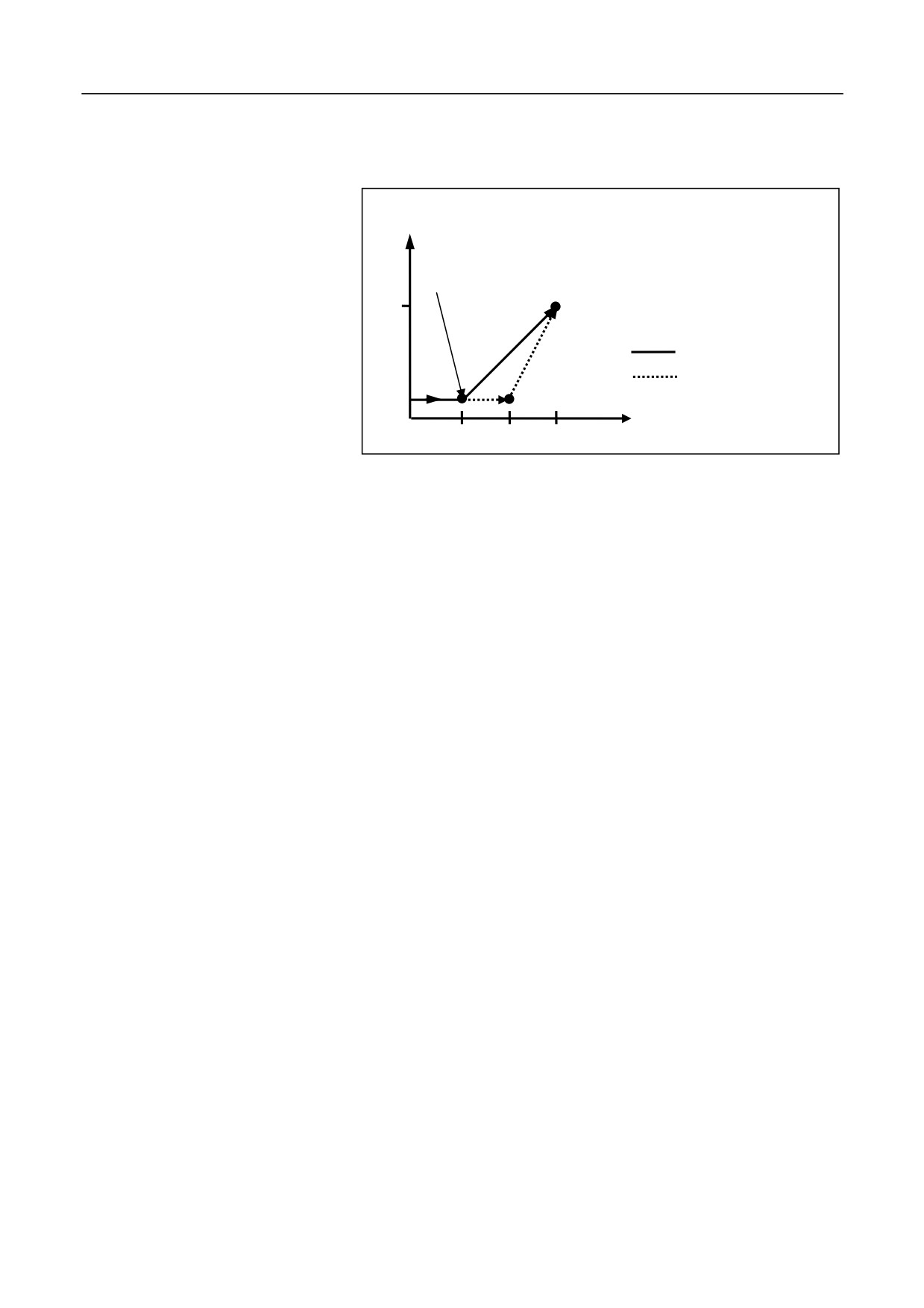
1.
The program block after G31 is incremental command.
G31L1G91X100.0F100;
Y50.0;
Input GOTO signal here
50.0
Y
100.0
Actual motion
X
Without GOTO signal
2.
The program block after G31 is absolute command to one axis.
G31L1G90X200.0F100;
Y100.0;
Y100.0
Input GOTO signal here
X200.0
Actual motion
Without GOTO signal
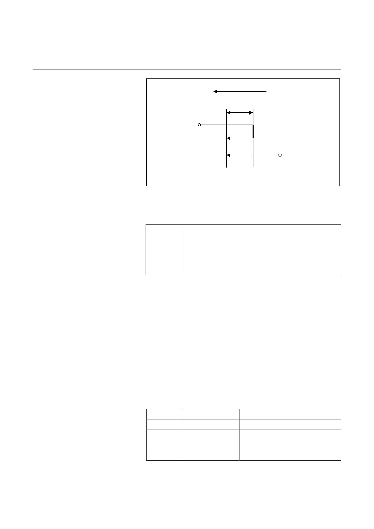
3.
The program block after G31 is absolute command to two axes,
61
5. Interpolation Functions
G31L1G90X200.0F100;
X300.0Y100.0;
Y
Input GOTO signal here
100
(300,100)
Actual motion
Without GOTO signal
X
100
200
300
62
6. Feed Functions
6 Feed Functions
This chapter includes the following sections:
6.1 Rapid Feed
6.2 Unidirectional Positioning
6.3 Define Feed Speed Unit
6.4 Exact stop verification
6.5 Cutting Mode
6.6 Feed Hold
6.7 High-Speed High-Precision Mode Selection
63

6. Feed Functions
6.1 Rapid Feed (G00)
In the G00 mode, the tool moves at the rapid feed speed to the specified
position.
Format
G00 IP_
Parameter
Description
IP
In the absolute value mode (G90): the coordinate value
of the end point in the workpiece coordinate system.
In the incremental value mode
(G91): the relative
movement amount of the end point away from the start
point.
Description
The rapid motion speed of each axis in the G00 command is defined by
the axis parameter Rapid Traverse Feed Rate (100034 axis 0). You
cannot specify it with the F command.
G00 is generally used for quick positioning before processing or fast tool
retreat after machining. In the positioning mode initiated by G00, the
tool speeds up to the specified speed from the start point of the block and
slows down when close to the target position. After reaching the end
point, the CNC system will execute the next block.
The rapid traverse speed can be adjusted with the override ratio
button on the control plane.
G00 is modal code, of which functions can be canceled by G01, G02, or
G03.
64
6. Feed Functions
6.2 Unidirectional Positioning (G60)
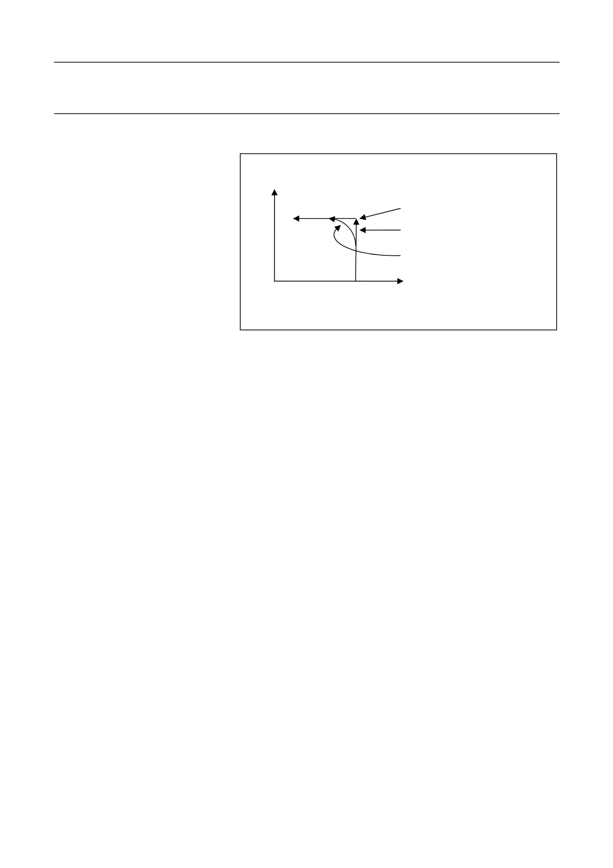
Positioning direction
Offset
Start point
Start point
End point
Format
G60 IP_
Parameter
Description
IP
In the absolute value mode (G90): the end point position
in unidirectional positioning.
In the incremental value mode (G90): the distance from
the current position to the end point.
Description
In order to eliminate the influence of backlash, you may control the axis
to conduct positioning in one direction.
As shown in the figure, conduct positioning in a common mode when the
motion direction is the same as the positioning direction; when the
motion direction is different from the positioning direction, move the
tool in the motion direction, then move one offset in the positioning
direction. Then the tool reaches the end point.
Offset Value
When running G60, you also need to specify the offset value and the
offset direction. The positive and negative values of the following
parameters indicate the offset directions of G60.
Axis
Parameter Index
Description
1st axis
Parm100030
G60 offset vector of the first axis.
G60 offset vector of the second
2nd axis
Parm101030
axis.
3rd axis
Parm102030
G60 offset vector of the third axis.
65
6. Feed Functions
Attention
1.
Conduct unidirectional positioning even if the tool movement is
zero.
2.
The specified overshoot in unidirectional orientation must be
greater than the backlash of the corresponding shaft; otherwise you
cannot completely eliminate the backlash during unidirectional
orientation.
Example
(Set 100030 to 10, G60 end point - parameter value of 10X030 = G60
center point)
%0008
G54
G00X20
G60X0; move to X-10, and then move to 0
M30
66
6. Feed Functions
6.3
Define Feed Speed Unit (G93, G94, G95)
During workpiece machining, the feed speed of linear interpolation (G01)
and circular interpolation (G02, G03) are defined by the value after F.
The feed speed unit is defined by G93, G94, and G95.
1.
M: three commands
y Feed per minute (G94)
After F, specify the tool feed per minute.
y Feed per revolution (G95)
After F, specify the tool feed per revolution around the spindle.
y Inverse-time feed (G93)
After F, specify FRN
2.
T: two commands
y Feed per minute (G94)
After F, specify the tool feed per minute.
y Feed per revolution (G95)
After F, specify the tool feed per revolution around the spindle.
Format
G93; Specify FRN feed
G94; Specify feed per minute
G95; Specify feed per revolution
G94
Feed per minute
In the G94 mode (feed per minute), F specifies the tool movement
amount per minute. Unit: mm/min (G21) or in/min (G20)
G95
67
6. Feed Functions
Feed per revolution
G95 specifies the tool movement amount per revolution around the
spindle as the feed rate F. Unit: mm/r (G21) or in/r (G20)
Only when the spindle is configured with an encoder, can G95 be
specified.
G93
FRN feed
FRN feed is achieved by specifying the time which is taken to execute
the current program block.
Attention
1.
G93, G94, and G95 are modal functions, which can be canceled by
each other. G94 is the default modal.
2.
In the FRN feed mode, if the calculated speed exceeds the
maximum cutting speed, the actual speed is limited to the maximum
cutting feed speed.
3.
G93 must be programmed in a separate line.
Example
%0008
G54X0Y0Z0; the F value in each mode below is 1000.
G94
G01X50F1000
M3S500
G95
G01Y50F2
G93
G01Z50F20; movement distance x F = final feed speed
M30
68
6. Feed Functions
6.4 Exact Stop Verification (G09)
Control the tool stop exactly at the end point of the program block.
Format
G09; specified in a separate line
Description
Stop exactly at the end point of the program block including G09 before
proceeding to execute another program block. The function is used for
machining sharp corners.
G09 is non-modal command, which is valid only in the defined program
block.
The difference between G09 and G61 is that G09 is valid in program
blocks but G61 is valid in the modal mode.
69
6. Feed Functions
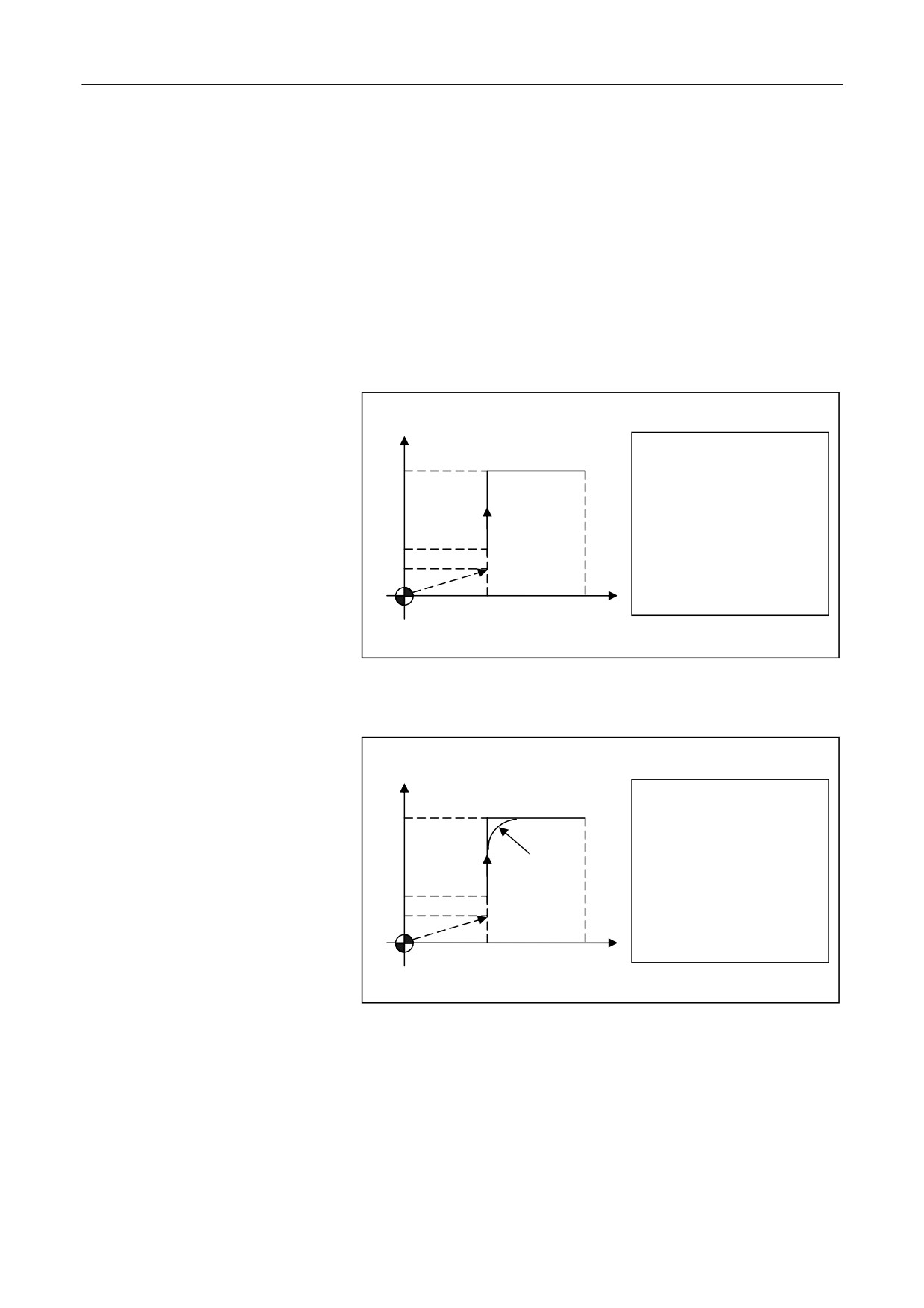
6.5 Cutting Mode (G61/G64)
The cutting mode is used to control feed speed.
Y
2
Position verification
Tool path in the exact stop mode
1
Tool path in the cutting or tapping
mode
O
X
Description
1.
G61: exact stop mode
In each block after G61, the programmed axis must exactly stop at
the end point of the block, and then proceed to the next block.
2.
G64: continuous cutting mode
In each block after G64, the programmed axis executes the next
block right after it begins to slow down
(not reaching the
programmed end point). However, in the block including position
commands (G00, G60) or exact stop verification command (G09),
or in the block excluding motion command, the position verification
will be executed only when the feed speed slows down to zero.
Attention
1. The programming contour of G61 is consistent with the actual
contour.
2. The difference between G61 and G09 is that G61 is modal
command.
3. The programming contour of G64 is inconsistent with the actual
contour. Its difference depends on the value of F and the angle
between the two paths. The greater the value of F is, the greater the
difference is.
4. G61 and G64 are modal commands, which can be canceled by each
70
6. Feed Functions
other.
5. After running small line programs and changing from the automatic
mode to the single block mode, the G64 command will execute the
splines in the look-ahead buffer, and then execute program blocks in
single block mode; therefore, a number of program blocks may be
continuously executed in a single block. Small lines program
includes programs generated by CAM and programs generated by
macro operation.
Example
1: Create a program for the machining as shown in the figure below: The
programming contour must be consistent with the actual contour.
Y
%0061
100
G92 X0 Y0 Z0
G91 G00 G43 Z-10 H01
G41 X50 Y20 D01
30
G01 G61 Y80 F300
20
X100
X
…
50
150
2: Create a program for the machining as shown in the figure below: no
stops between program blocks.
Y
%0061
100
G92 X0 Y0 Z0
G91 G00 G43 Z-10 H01
Actual path
G41 X50 Y20 D01
30
G01 G64 Y80 F300
20
X100
X
…
50
150
71
6. Feed Functions
6.6 Feed Hold (G04)
During automatic running, you may use G04 to pause the tool feed. The
system will automatically execute the ongoing program blocks after the
specified time is expired.
Format
G04 P_; Feed hold
G04 X_;
X: Unit: second
P: Unit: millisecond
Attention
1.
The minimum feed hold time is specified as an interpolation cycle
(Parm000001). If the specified time is less than an interpolation
cycle, it will be executed as an interpolation cycle.
2.
The value after X cannot be greater than 2000; otherwise, the
system will not execute the program.
72
6. Feed Functions
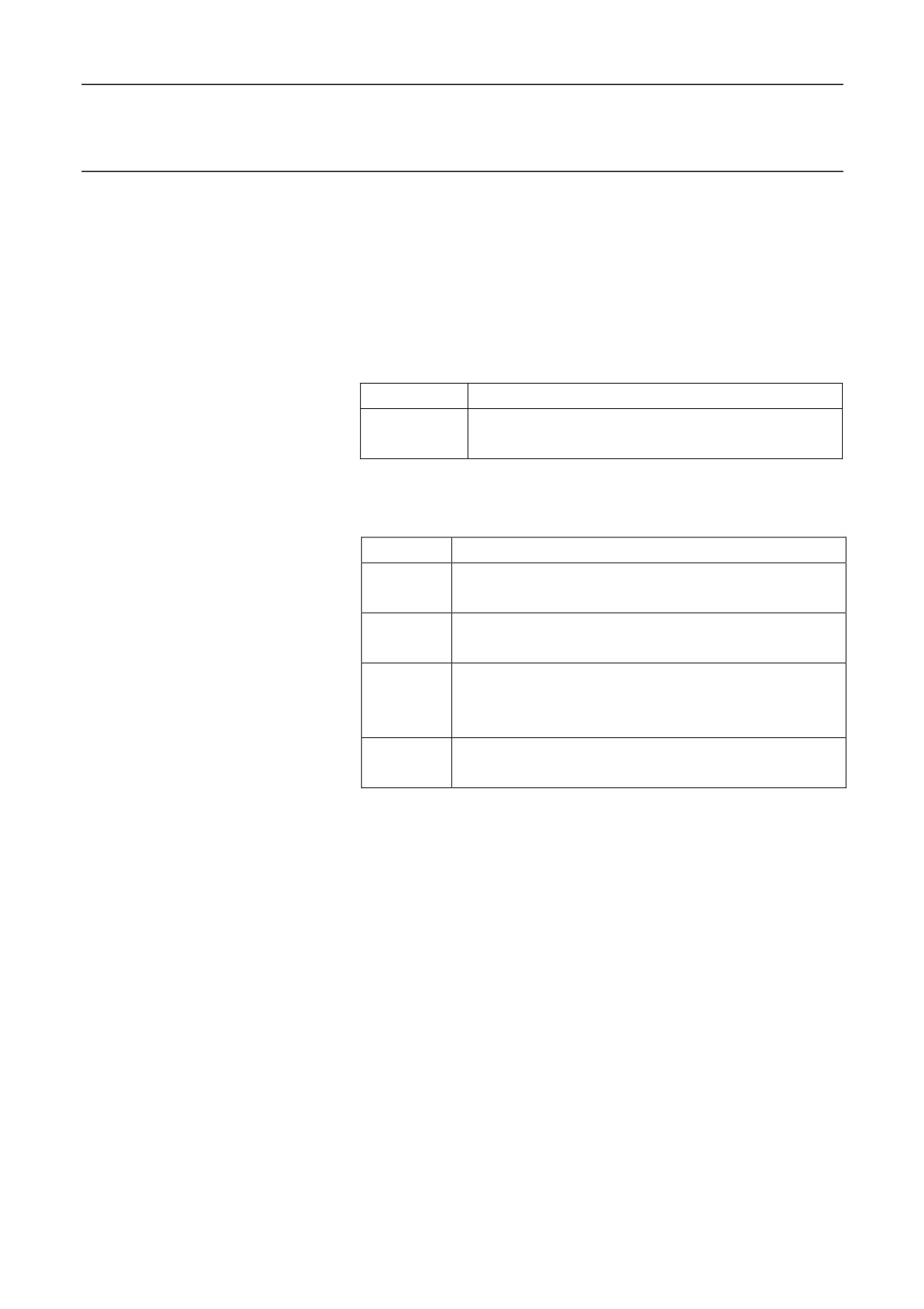
6.7 High-Speed High-Precision Mode Selection (M) (G05.1)
The command is used to switch among different machining modes to
meet different requirements.
Format
G05.1 Q_; Specify machining mode
……
G05.1 Q0; Default mode
Parameter
Description
Q_
Select a machining mode 0, 1, 2 and 3, which can be
switched by G05.1Q_.
Description
Command
Description
G05.1Q0
Default mode; focuses on the balance between efficiency
and precision
G05.1Q1
High-precision mode; focuses on the machined surface
and dimensional accuracy.
G05.1Q2
High-speed and high-precision mode; focuses on
processing smoothness and the balance between the
efficiency and precision.
G05.1Q3
High-speed mode; focuses on the processing efficiency,
improves the processing speed for free curve.
Attention
G05.1Q_ must be specified in a separate line.
73
7. Reference Point
7 Reference Point
Reference point is a fixed position on the CNC machine, based on which,
the workpiece coordinate system can be established, or the tool change
and other fixed operations can be conducted.
The chapter includes the section below:
7.1 Return to Reference Point
74
7. Reference Point
7.1 Return to Reference (G28, G29, G30)
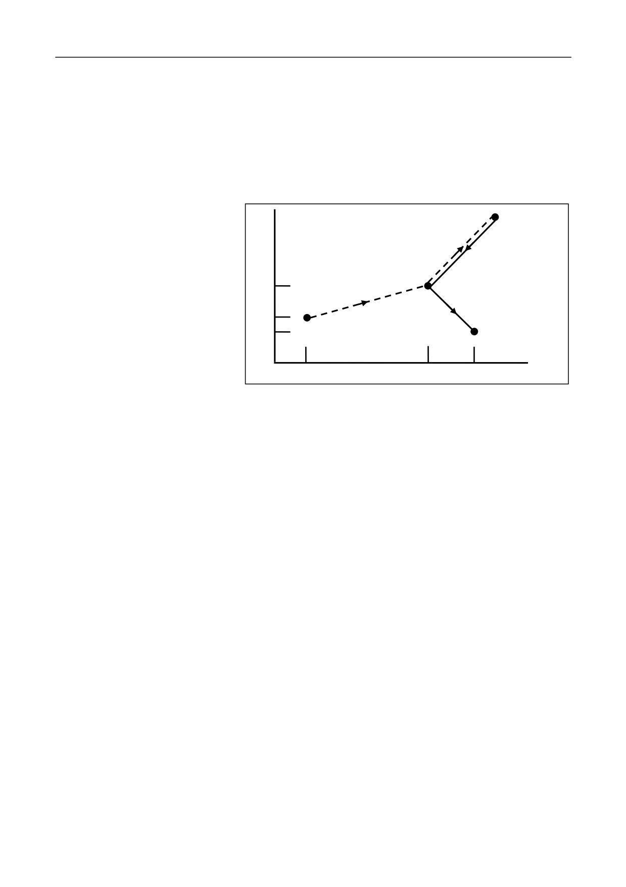
Reference point is a fixed point on the machine. There are a total of five
reference points: the first, the second, the third, the fourth and the fifth
reference points. You may use the reference command to easily move the
tool to the reference points. The referent points can be used as the tool
change position.
Take the axis 0 as an example. You may set five reference points in the
machine coordinate system by setting the reference point position
parameters (100017, 100021, 100022, 100023, and 100024).
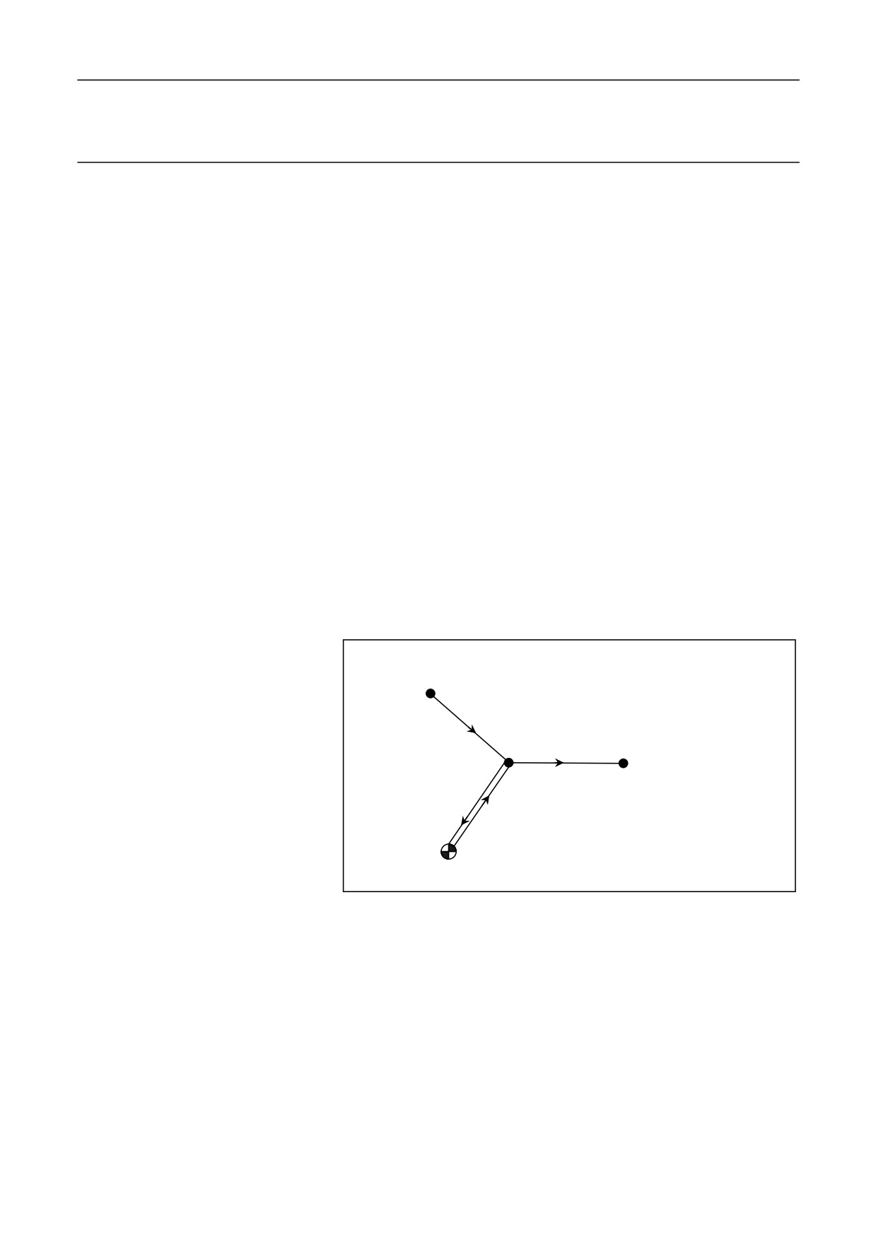
Execution procedure
When you execute the command of returning to the reference point, the
tool automatically passes through the intermediate point to reach the
reference point rapidly. At the same time, the specified intermediate
point is saved in the CNC system, and the tool automatically passes
through the intermediate point and moves along the specified axis to the
end point.
The figure below shows the process that a tool returns to the reference
point:
Start point
Intermediate point
end point
Reference point
Automatically home to reference
point
G28 IP_; Return to the first reference point
G30 P2 IP_; Return to the second reference point (P2 can be omitted )
G30 P3 IP_; Return to the third reference point
G30 P4 IP_; Return to the fourth reference point
G30 P5 IP_; Return to the fifth reference point
75
7. Reference Point
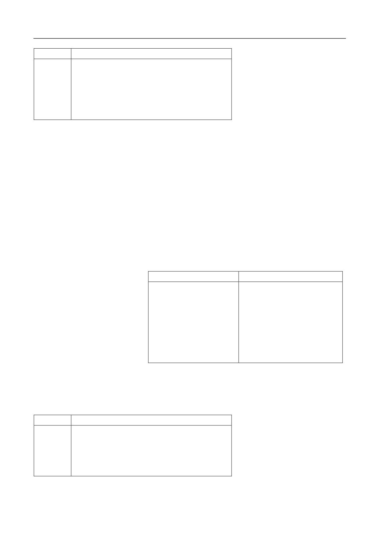
Parameter
Description
IP
In the absolute value mode (G90), specify the absolute
position of the intermediate point; in the relative value
mode (G91), specify the distance from the intermediate
point to the start point. You do not need to calculate the
The coordinate value specified by IP is
specific movement amount from the intermediate point
the value in the workpiece coordinate
to the reference point.
system. Only the axis specified with the
intermediate point can move when the command of automatic returning
to reference is executed.
G29 IP_;
The coordinate value specified by IP is the value in the workpiece
coordinate system.
The intermediate point is that of G28, G30 specified previously.
Return from reference point
The table below describes the running mode for the relative value (G91):
Execute program
Workpiece coordinate system x, y, z
G54X0Y0Z0
0,0,0
G91G28X10Y10Z10
10,10,10--------->0,0,0
X100
100,0,0
Y100
100,100,0
Z100
100,100,100
G29X10Y10Z10
10,10,10--------->20,20,20
Move to the intermediate point of
G28, and then execute G91
Parameter
Description
IP
In the absolute value mode (G90), specify the end point;
in the relative value mode (G91), the intermediate point
of G29 must be that of G28 specified previously. To
execute G29, you may execute G91 based on the
intermediate point of G28.
76
7. Reference Point
G29 can be executed only after G28 or G30 has been executed;
otherwise, the execution may be abnormal as there is no intermediate
Attention
point.
Y
R
(Reference
Return to reference point (G28)
AĺBĺR
point)
Return from reference point
RĺBĺC
(G29)
B (Intermediate point)
Example
500
300
200
A (start point)
C (End point)
200
1000
1300
X
%1234
G54
G00 X200Y300
G28 G90 X1000.0 Y500.0; program from point A to B. Move through the
intermediate point B, and to the reference point R.
T6;
M06; change tool at the reference point
G29 X1300.0 Y200.0; program from point B to C. Move from the
reference point R, through the intermediate point B, and to the end point
specified by C
M30
77
8. Coordinate System
8 Coordinate System
reach a predefined position, which is defined based on the coordinate
values within a coordinate system. The coordinate value is specified by
program axis value, so as to process workpiece according to the specific
program.
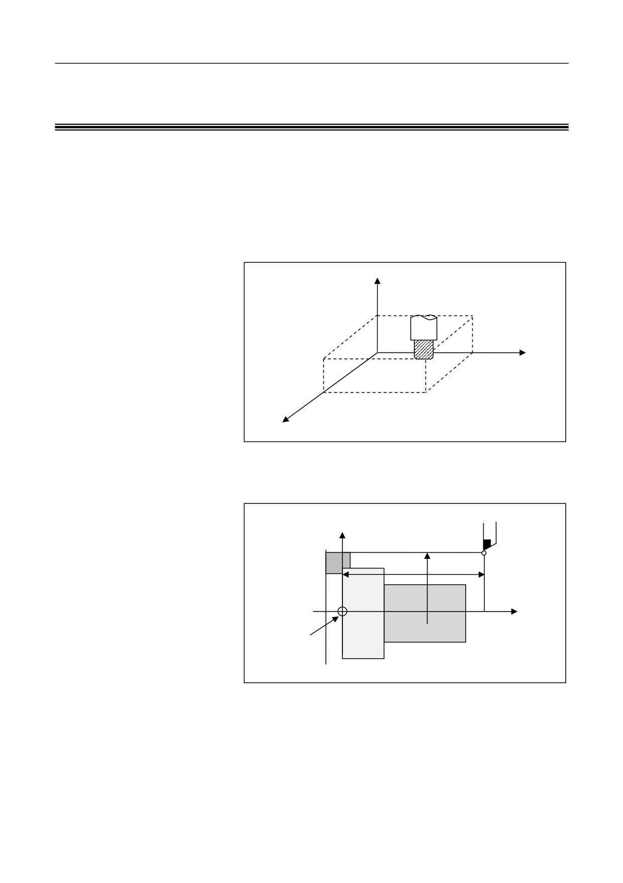
• Milling machine
(use X40.0 Y50.0 Z25.0 to define the tool
position)
Z
25.0
Y
50.0
40.0
X
• Turning machine (use X50.0 Z40.0 to define the tool position)
X
40.0
50.0
Z
Origin
This CNC system provides the following coordinate systems:
• Machine coordinate system
• Workpiece coordinate system
• Local coordinate system
During the machining, the tool may
•
78
8. Coordinate System
This chapter includes the following sections:
8.1 Machine Coordinate System Programming
8.2 Define Workpiece Coordinate System
8.3 Define Local Coordinate System
8.4 Select Coordinate System Plane
79
8. Coordinate System
8.1 Machine Coordinate System Programming (G53)
There is a fixed mechanical point on the machine, which can be used as a
datum point of the machine. It is called as the machine origin, of which
position is defined by Zero Block or Grating Zero point. This point is
used as the origin to establish the coordinate system which is called the
machine system.
After power on, you may establish the machine coordinate system by
manually returning to the reference point. Once the machine coordinate
system is established, it remains unchanged before cutting off the power
supply.
Format
G53 IP_;
Parameter
Description
IP
Target position in the machine coordinate system
Define Machine Coordinate
Before calling G53, the machine coordinate system must be established
System
by returning to the reference point.
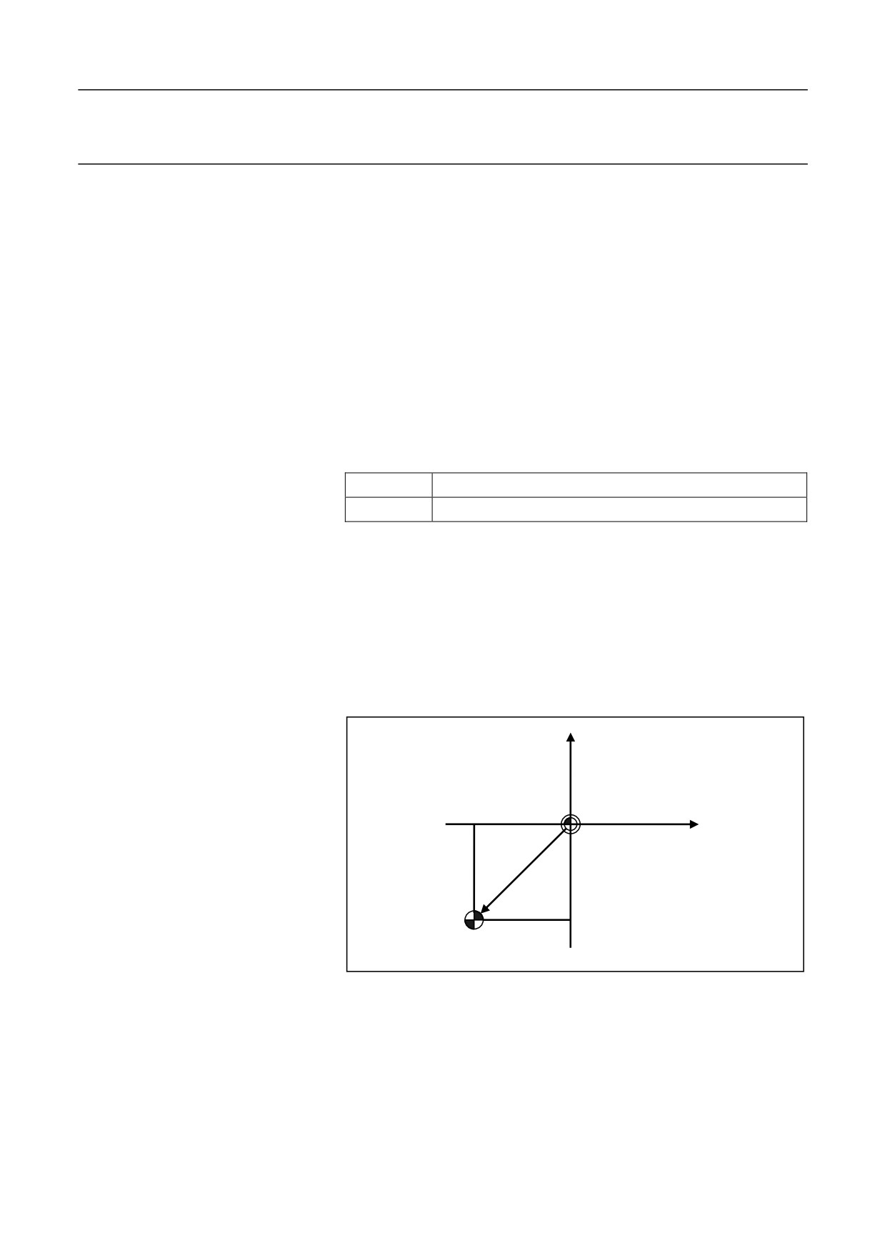
The reference point does not coincide with the origin of the machine
coordinate system. The figure below shows the relationship between
them:
Machine coordinate system
Machine origin
ȕ
Į
Reference point
Attention
1.
G53 is a non-modal command, which must be specified at the
current line when conducting the machine coordinate programming.
80
8. Coordinate System
2.
The target position specified by
G53 cannot be relative
programming. You must use
absolute command for
programming.
3.
The compensation functions such as tool radius compensation, tool
length compensation, and cutter radius compensation are cleared
when the G53 command is specified.
4.
Before specifying the G53 command, you must set the machine
coordinate system; therefore it is necessary to manually return to the
reference point or return to the reference point with the G28
command after power on. You may skip this operation when using
the absolute position encoder.
81
8. Coordinate System
8.2 Workpiece Coordinate System
The coordinate system used for workpiece machining is called as a
workpiece coordinate system.
The workpiece coordinate system is predefined in the CNC system
(Define workpiece coordinate system).
You may create programs in the defined workpiece coordinate system
and machine the workpiece (Select workpiece coordinate system).
You may move the origin of the defined workpiece coordinate system to
change the workpiece coordinate system (Change workpiece coordinate
system).
8.2.1 Define Workpiece Coordinate System (G92)
workpiece coordinate system:
1. Use G92 to define the workpiece coordinate system.
2. Define the workpiece coordinate system through the selecton of
G code.
Use the workpiece coordinate system on the HMI interface to
define six standard workpiece coordinate systems (G54-59) and
60 extended workpiece coordinate systems (G54.X) (for milling
machining center), and then use the corresponding program
commands to define the workpiece coordinate.
3. For turning machines, in the absolute tool offset compensation
mode, you may define the origin of the workpiece coordinate
system via T commands (see section 10.1)
Under the absolute commands, the workpiece coordinate system must be
established by using any of the methods above.
There are three methods to define a
Format
G92 IP_;
Parameter
Description
IP
The orientation distance from the origin of the
coordinate system to the tool start point.
82
8. Coordinate System
Set Workpiece Coordinate System
The G92 command can be used to set the relative position of the tool
start point to the coordinate origin. Thereby defining the workpiece
coordinate system. Once the workpiece coordinate system is defined, the
command value in absolute programming is the coordinate value in the
workpiece coordinate system.
1. The execution of this program block is only to set the workpiece
Attention
coordinate system, but the tool will not move.
2. G92 is a non-modal command.
3. In the tool length compensation mode of milling machines, the
coordinate system set G92 command is the specified coordinate
system before conducting the compensation. However, the G code
cannot be executed in the program blocks where the tool length
compensation vector changes. For example, it is cannot be executed
in the following blocks:
• Program blocks where the G43/G44 is specified.
• Program blocks where H code is specified in G43/G44 modes
• Program blocks where G49 is specified in G43/G44 modes
• Program blocks where the compensation vector is canceled by
G28/G53 in G43/G44 modes and the vector is restored
In addition, when setting the workpiece coordinate system with G92, the
programs before it will be stopped and the tool length compensation
defined by MDI cannot be changed.
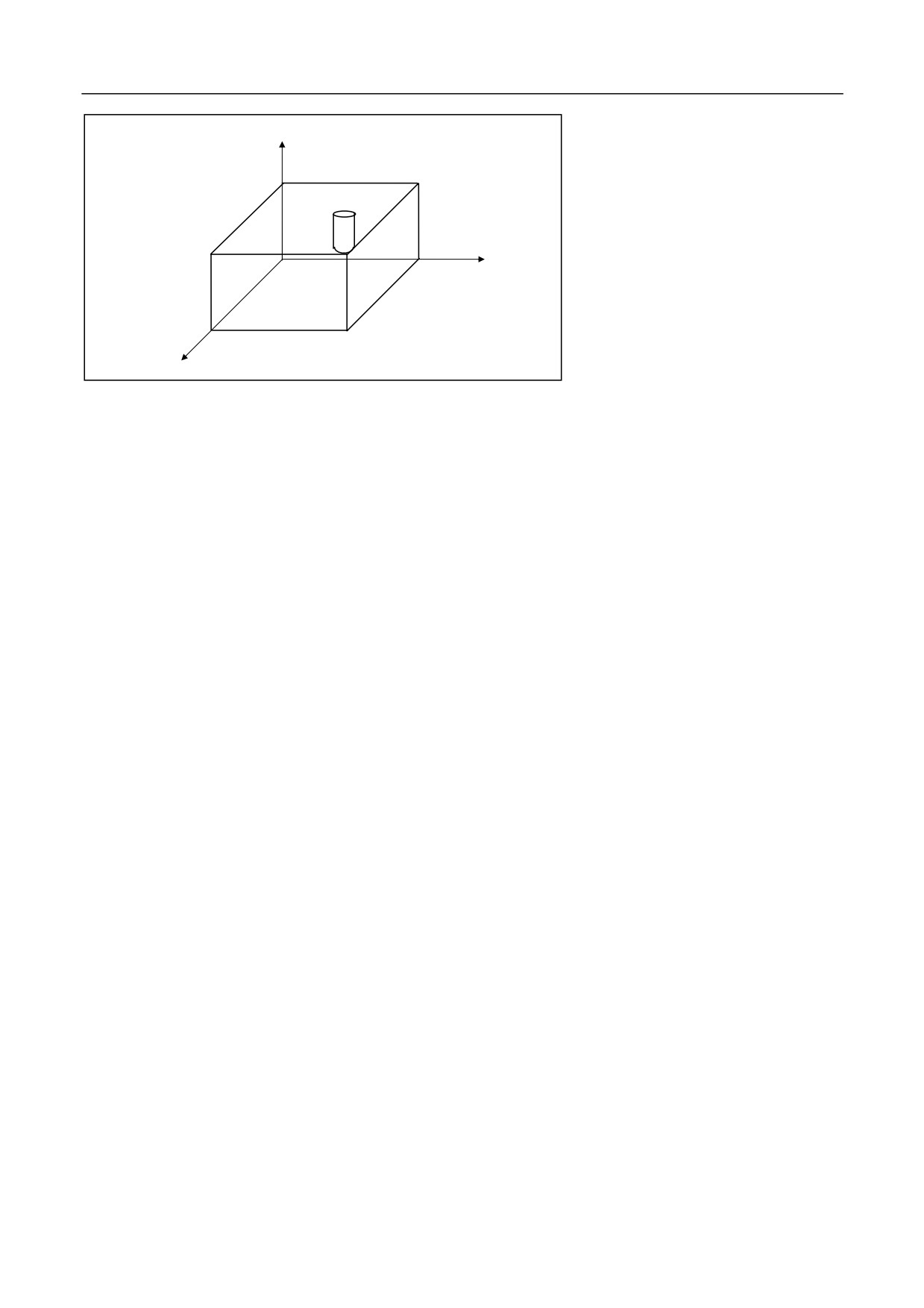
Use G92 to set the workpiece coordinate system as shown below:
Example
G92 X30.0 Y30.0 Z20.0
83
8. Coordinate System
Z
20.0
Tool start point
Y
30.0
Program origin
30.0
X
84
8. Coordinate System
8.2.2 Select Workpiece Coordinate System (G54-G59)
You may select the following workpiece coordinate systems that have
been defined:
1.
In the workpiece coordinate system defined by G92, the absolute
command defined is a position in this coordinate system.
2.
Select among 6 standard workpiece coordinate systems of G54 to
G59.
3.
For milling machines and machining centers, select among
60
extended workpiece coordinate systems of G54.X.
4.
For turning machines, in the absolute tool offset mode, select a
workpiece coordinate system with T commands. For details, see
section 10.1.
Example
%1234
G54
G90 G00 X100 Y100 Z50; Locate X=100 Y=100 Z=50 in the G54
coordinate system
M30
8.2.3 Change Workpiece Coordinate System (G10)
You may change the workpiece coordinate system defined in the
following modes by changing an external workpiece origin offset or
workpiece origin offset:
1.
Workpiece coordinate systems defined by G54-G59
• Set the Coordinate system on the HMI interface.(see relevant
section of Operation manual)
• Select the G code to define the workpiece coordinate systems
• Change the coordinate system origin with G10 command(for
details, see section 15)
2.
Workpiece coordinate systems defined by G54.X for milling
machines
85
8. Coordinate System
•
• Set the Coordinate system on the HMI interface.(see relevant
section of Operation manual)
• Select the G code to define the workpiece coordinate systems
• Change the coordinate system origin with G10 command(for
details, see section 15)
•
3.
Workpiece coordinate systems defined with absolute tool offset for
turning machines
• Set the Coordinate system on the HMI interface.(see relevant
section of Operation manual)
• Select the G code to define the workpiece coordinate systems
8.2.4 Select Extended Workpiece Coordinate System (G54.x)
In addition to the six standard workpiece coordinate systems, you may
select extended workpiece coordinate systems for milling machines as
required.
A total of
60 extended workpiece coordinate systems for milling
machines are available.
Format
G54.n, G54.1Pn, G54Pn: Select No. n workpiece coordinate system
Parameter
Description
n
Number of Extended workpiece coordinate system,
ranging from 1 to 60.
Example
%1234
G54.18; or G54.1P18, G54P18
G90 G00 X100 Y100 Z50; locate the position where X=100 Y=100 Z=50
in the 18th coordinate system
M30
86
8. Coordinate System
8.3 Define Local Coordinate System (G52)
During workpiece coordinate system programming, you may create a sub
workpiece coordinate system, which is called local coordinate system.
Format
G52 IP_; Define the local coordinate system
G52 IP 0; Cancel the local coordinate system
Parameter
Description
IP
Define the origin of the local coordinate system
Description
The G52 IP_; command can be used to create the local coordinate
systems in all workpiece coordinate systems. The origin of the local
coordinate system becomes the position defined by IP_ in the
corresponding workpiece coordinate system.
Once the local coordinate system is defined, the axial movement
command to be specified will be the coordinate value in the local
coordinate system.
If you want to cancel the local coordinate system or specify coordinate
value in the workpiece coordinate system, you may make the origin of
the local coordinate system coincide with the origin of the workpiece
coordinate system.
Example
%1234
G55; select G55, assuming that the value of G55 in the machine
coordinate system is (10, 20)
G1 X10Y10F1000; move to the point (20, 30) in the machine coordinate
system
G52 X30Y30; set local coordinate system based on G55 in the workpiece
coordinate system, with the origin of (30, 30)
G1 X0Y0; move to the origin of the local coordinate system (the current
position in the machine coordinate system is (40, 50))
G52 X0Y0; cancel the local coordinate system, and restore the G55
87
8. Coordinate System
workpiece coordinate system
G1 X10Y10; move to the machine coordinate system (20, 30)
M30
Attention
If the local coordinate system is not canceled and the workpiece
coordinate system changes, the local coordinate system is still valid.
Example
%1234
G54; select G54, assuming that the value of G54 in the machine
coordinate system is (10, 10, 10)
G0X0Y0Z0; move to the point (10, 10, 10) in the machine coordinate
system
G52X20Y20Z20; set local coordinate system based on G54 in the
workpiece coordinate system, with the origin of (20, 20, 20)
G0X0Y0Z0; move to the point (30, 30, 30) in the machine coordinate
system
G55; select G55, assuming that the value of G55 in the machine
coordinate system is (12, 12, 12)
G0X0Y0Z0; move to the point (32, 32, 32) in the machine coordinate
system; the local coordinate system is still valid.
G52X0Y0Z0; cancel the local coordinate system and restore the G55
coordinate system
G0X0Y0Z0; move to the point (12, 12, 12) in the machine coordinate
system; the local coordinate system is still valid.
M30
88
8. Coordinate System
8.4 Select Coordinate Planes (G17, G18, G19)
The coordinate plane selection command G17/G18/G19 is used to select
machining planes during circular interpolation, cutter radius
compensation (M), rotation transformation (M), etc.
Description
G code
Plane
G17
XY plane
G18
ZX plane
G19
YZ plane
Attention
G17, G18, and G19 are modal functions, which can be canceled by each
other.
The motion command has nothing to do with the plane selection. For
example, the Z axis moves even the command G17 G01 Z10 is executed.
89