HNC-818. User Manual - page 1
Contents
Contents
Preface
i
Contents
ii
I Product Overview
1
1 Overview
2
2 Symbol Description
3
II NC Functions
4
1 Overview
5
1.1 CNC Machine Programming
6
1.2 Machine Coordinate System
7
1.3 Machine Origin
9
1.4 Reference Point of Machine
10
1.5 Workpiece Coordinate System and Workpiece Origin
11
1.6 Programming Origin
12
1.7 Absolute and Relative Coordinate Systems
13
2 Preparation (G-Code)
14
2.1 G-Codes (T)
15
2.2 G-Codes (M)
17
3 Program Structure
20
3.1 Command Format
21
3.2 Program Block Format
22
3.3 General Program Structure
23
3.4 Program File Name
24
3.5 Program File Properties
25
3.6 Sub-Programs
26
4 Auxiliary Functions
27
4.1 M Commands
28
4.2 S Commands
34
4.3 T Commands
35
5 Interpolation Functions
38
5.1 Linear Feed (G01)
39
5.2 Arc Feed (G02, G03)
42
5.3 Cylindrical Helical Interpolation (G02, G03)
47
5.4 Specify Imaginary Axis and Sine Interpolation (G07)
50
5.5 NURBS Spline Interpolation (NURBS)
51
5.6 Thread Cutting (G32)
54
5.7 HSPLINE Spline Interpolation (HSPLINE)
58
ii
Contents
5.8 GOTO Function (G31)
60
6 Feed Functions
63
6.1 Rapid Feed (G00)
64
6.2 Unidirectional Positioning (G60)
65
6.3 Define Feed Speed Unit (G93, G94, G95)
67
6.4 Exact Stop Verification (G09)
69
6.5 Cutting Mode (G61/G64)
70
6.6 Feed Hold (G04)
72
6.7 High-Speed High-Precision Mode Selection (M) (G05.1)
73
7 Reference Point
74
7.1 Return to Reference (G28, G29, G30)
75
8 Coordinate System
78
8.1 Machine Coordinate System Programming (G53)
80
8.2 Workpiece Coordinate System
82
8.3 Define Local Coordinate System (G52)
87
8.4 Select Coordinate Planes (G17, G18, G19)
89
9 Coordinate Values and Dimension Unit
90
9.1 Absolute Commands and Incremental Commands (G90, G91)
91
9.2 Dimension Unit Selection (G20, G21)
93
9.3 Polar Coordinate Programming (M) (G16, G15)
94
9.4 Diameter and Radius Programming (T) (G36, G37)
98
10 Tool Compensation Functions
100
10.1 Tool Offset (T)
101
10.2 Tool Nose Radius Compensation (T) (G40, G41, G42)
104
10.3 Introduction to Tool Radius Compensation (M) (G40, G41, G42)
113
10.4 Description of Tool Radius Compensation (M) (G40, G41, G42)
117
10.5 Tool Length Compensation (M) (G43, G44, G49)
126
11 Programming Simplification Functions
131
11.1 Mirroring Function (M) (G24, G25)
132
11.2 Scaling Function (M) (G50, G51)
136
11.3 Rotation Function (M) (G68, G69)
139
11.4 Direct Programming based on Blueprint Dimensions (T)
142
12 Fixed Cycle
146
12.1 Drilling Fixed Cycle for Milling Machines (M)
147
12.2 Simple Cycle for Turning Machines (T)
239
12.3 Fixed Cycle for Drilling of Turning Machines (T)
255
12.4 Compound Cycle for Turning Machines (T)
261
12.5 Special Cases in Fixed Cycle
281
13 User Macro Program
282
13.1 Variables
283
13.2 Operation Instructions
290
13.3 Macro Statement
292
13.4 Calling Macro Programs
297
14 Spindle Functions
308
Contents
14.1 Constant Linear Speed Cutting Control (T) (G96, G97)
309
14.2 C/S Axis Switching Function (CTOS/STOC)
312
14.3 Spindle Synchronization (G116, G117)
313
15 Programmable Data Input
315
15.1 Programmable Data Input (G10, G11)
316
16 Axis Control Functions
320
16.1 Cycle Function of the Rotation Axis
321
16.2 Reference of Grating Ruler with Distance-Code
322
17 Other Functions
324
17.1 Stop Read -ahead (G08)
325
17.2 Redefine Rotary Axis Angle Resolution (G115)
326
17.3 Axis Release (G101) and Axis Obtaining (G102)
327
17.4 Command Channel Loader (G1030) and Running (G103.1)
329
17.5 Channel Synchronization (G104)
330
17.6 Alarms (G110)
332
iv
I Product Overview
1
1. Overview
1 Overview
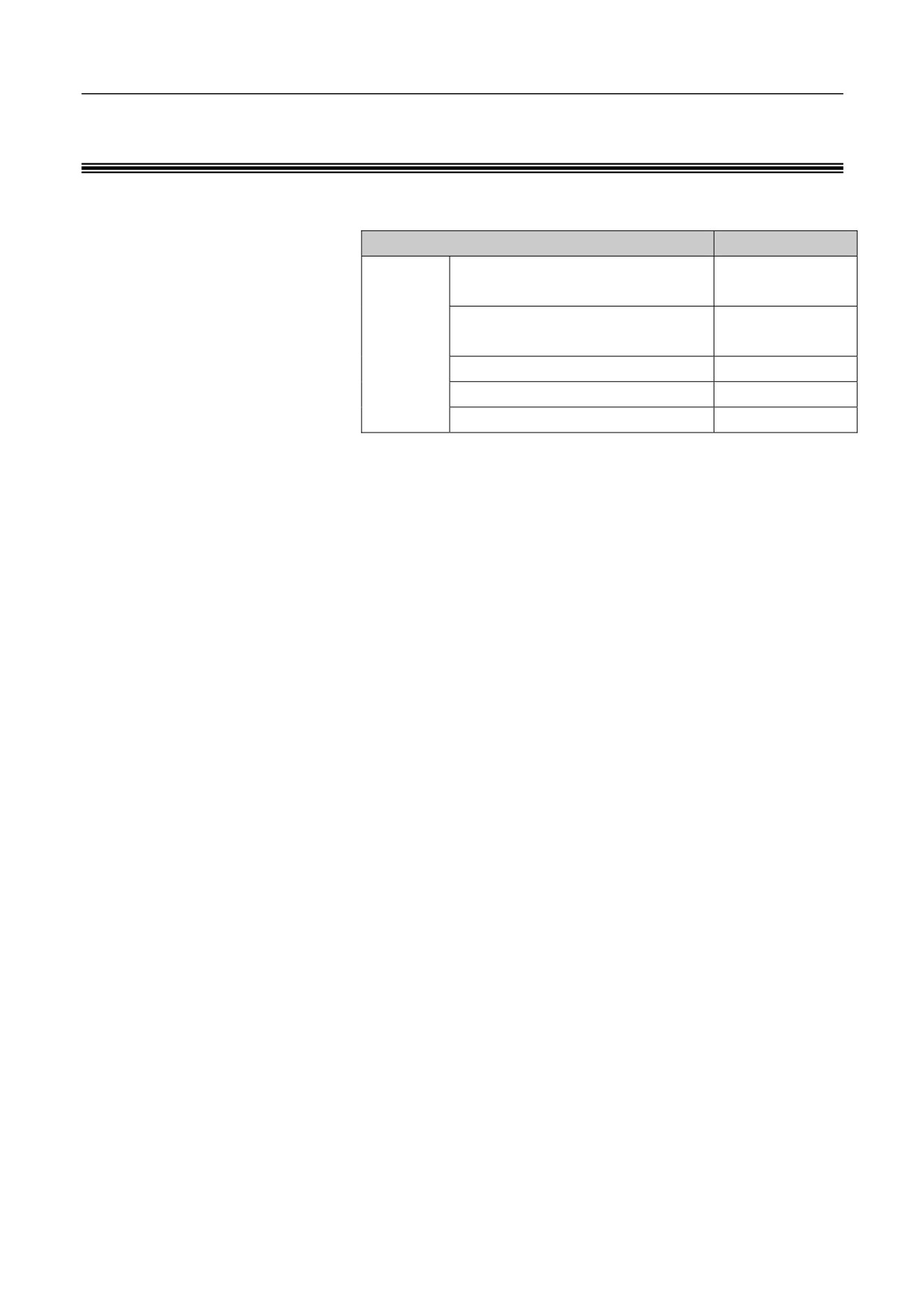
This documentation describes the following CNC systems:
CNC System
Abbreviation
HNC-818A Turning Unit (with
HNC-818A-TU-H
handheld unit)
HNC-818A Turning Unit (without
HNC-818A-TU-X
HNC-818
handheld unit)
HNC-818B Turning Unit
HNC-818B-TU
HNC-818A Milling Unit
HNC-818A-MU
HNC-818B Milling Unit
HNC-818B-MU
2
2. Symbol Description
2 Symbol Description
The symbols used in this documentation:
M: description valid only in the Milling Unit
T: description valid only in the Turning Unit
IP_: combination of any axis, e.g. X_ Y_ Z_ …. Coordinate axis values
are in the position of "_" in actual programming.
3
II NC Functions
4
1. Overview
1 Overview
This chapter includes the following sections:
1.1 CNC Machine Programming
1.2 Machine Coordinate System
1.3 Machine Origin
1.4 Reference Point of Machine
1.5 Workpiece Coordinate System and Workpiece Origin
1.6 Programming Origin
1.7 Absolute and Relative Coordinate Systems
5
1. Overview
1.1 CNC Machine Programming
CNC machines conduct workpiece machining based on programming.
The programming has a direct impact on the quality of machining,
productivity, and lifecycle of cutting tools. A good programmer should
have the abilities to master and flexibly use the CNC machine
programming.
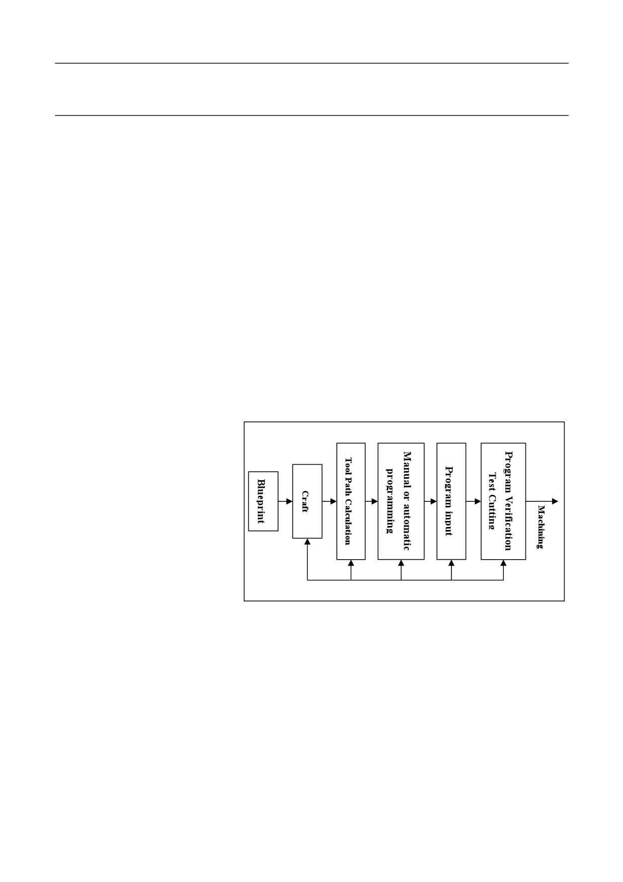
Programming means that a programmer, by referring to the workpiece
machining blueprint and craft, creates program codes and instructions for
the workpiece cutting process, machining path, auxiliary operations
during the machining such as tool change, cooling, clamp, and clockwise
(CW) and counter clockwise (CCW) rotation of spindle, etc. Then the
programmer inputs all the programs into the CNC system to run the CNC
machine for the workpiece machining. The CNC programming indicates
the process to create CNC codes and instructions based on the blueprint
and craft, and input them to the CNC system.
The figure below shows the general programming methods and
procedure:
Edit
6
1. Overview
1.2
Machine Coordinate System
Machine coordinate system is a geometric coordinate system and a fixed
coordinate on the machine, which is established to determine the position
of the workpiece on the machine, the special position and motion scope
of the motion parts. In the machine coordinate system, the workpiece is
believed stationary and the tool is in motion. This allows programmers to
determine the machining process based on the blueprint without
considering the movement of the workpiece and the tool.
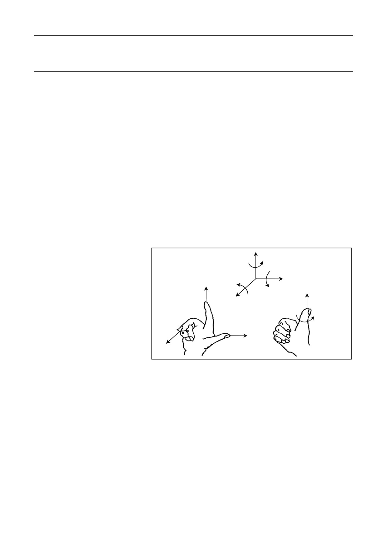
Standard machine coordinate system adopts the right hand Cartesian
coordinate system. The coordinate is named X, Y, Z which is often
referred to as the basic coordinate system shown in the figure below. It
follows the right-hand rule: stretching out the right hand thumb,
forefinger and middle finger, and keeping them mutually perpendicular;
then the thumb points in the positive direction of the X axis (+X), the
index finger points in the positive direction of the Y axis (+Y), and the
middle finger points in the positive direction of the Z axis (+Z).
+Y
+B
+X
+C
+Y
+A
+X, +Y, +Z
+Z
+A, +B, +C
+X
+Z
The letters A, B, and C are used to define the circumferential feed
coordinate which rotates around X, Y, and Z or the axis parallel to the X,
Y, and Z. According to the right-hand screw rule, if the thumb points in
the direction of +X, +Y, or +Z, the rotation direction of the remaining
four fingers point in the direction of +A, +B and +C.
• Define the Z axis
The axis parallel to the spindle is the Z axis. For the machine
without a spindle, Z axis is perpendicular to the workpiece
clamping surface. The positive direction of Z (+Z) is the direction
where the tool moves away from the workpiece.
7
1. Overview
•
•
Define the X axis
On the machine where the tool rotates, such as milling machine,
drilling machine, or boring machine, if the Z axis is horizontal, the
X axis is positive in the right direction when looking from the tool
(spindle) to the workpiece; If the Z axis is vertical, X axis is
positive in the right direction when looking from the spindle to the
column. The above are based on the motion of tool relative to
workpiece.These directions are relative directions of the tool to the
motion workpiece.
On the machine where the tool rotates, such as turning machine or
grinding machine, the X axis motion is in the radial direction of the
workpiece and parallel to the cross carriage. The direction where
the tool moves away from the workpiece rotation center is the
positive direction of the X axis.
•
Define the Y axis
After defining the positive directions of X and Z axis, you may
define the positive direction of the Y axis based on the right-handed
rectangular Cartesian coordinate system. That is, within the ZX
plane, rotate from + Z to + X, and the right hand-screw should
advance along the + Y direction.
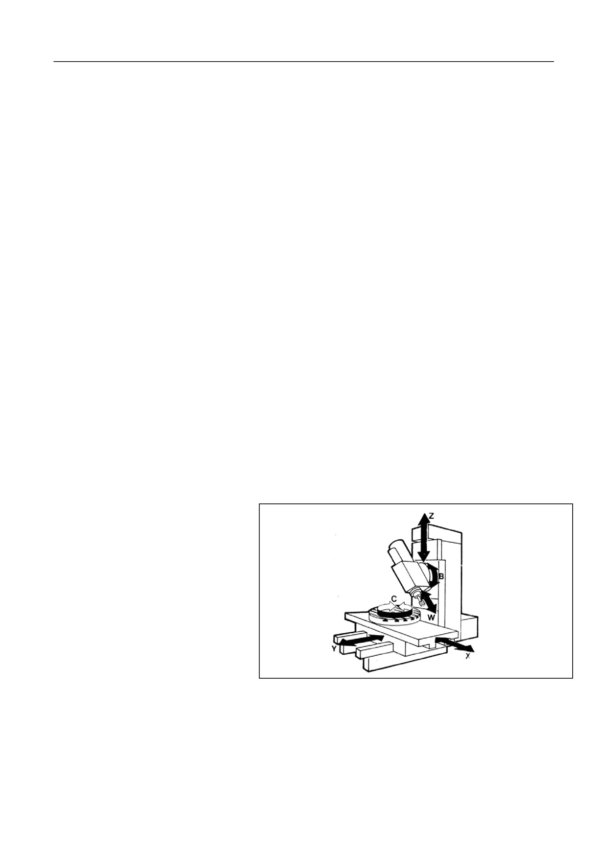
This may differ based on the machine types. The figure below
shows the coordinate system of a six-axis machining center:
•
8
1. Overview
1.3 Machine Origin
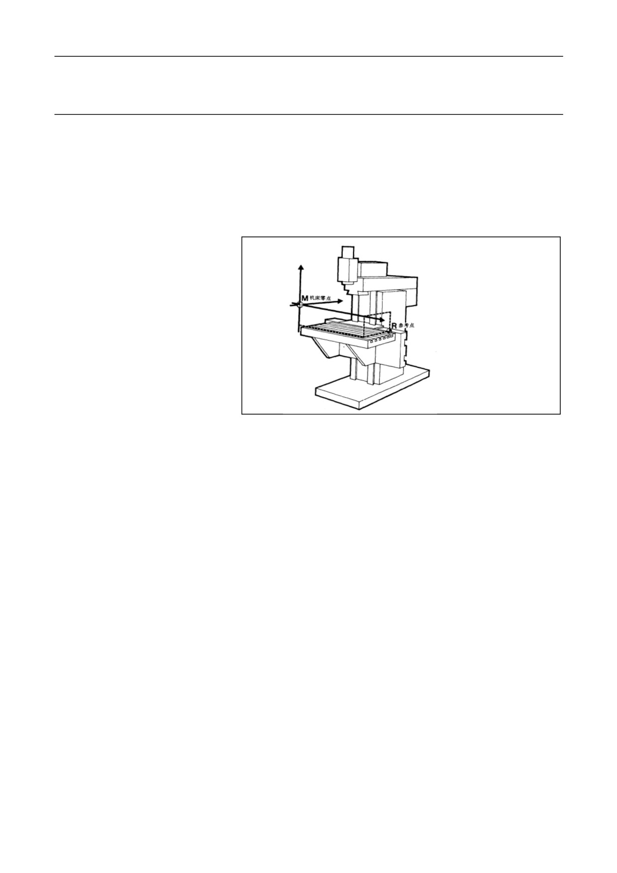
The Machine Origin is a fixed point on the machine, which is defined by
the machine manufacturer. It is a benchmark of workpiece coordinate
system, programming coordinate system and reference point. The
Milling Machine Origin may differ for different machine manufacturers.
Some are defined at the center of the machine work table, and some are
defined at the end of the feed travel.
M:machine origin; R: reference point
The origin of the machine is called
Machine Origin (X=0, Y=0, Z=0).
9
1. Overview
1.4 Reference Point of Machine
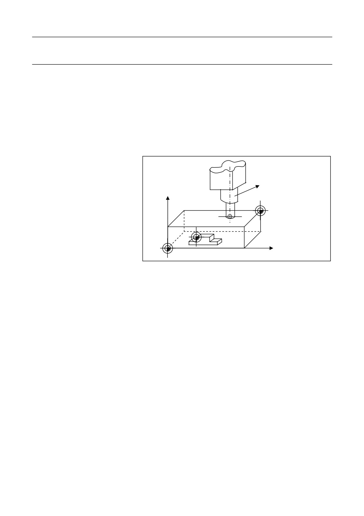
The machine reference point is exactly defined by the machine
manufacturer in each feed axis with limit switch. The coordinate values
are input into the numerical control system, which are fixed by the
mechanical block along each axis. You may return the tool or the work
table to the reference point by pressing the Reference key on the control
panel. Usually in the CNC milling machines and machining centers, the
machine reference point is coincident with the machine origin. See the
figure below:
Y
Z
R: Reference Point
W: Workpiece Origin
M: Machine Origin
X
10
1. Overview
1.5
Workpiece Coordinate System and Workpiece Origin
The workpiece coordinate system is used to define the position of the
workpiece geometry elements (points, straight lines and arcs). The origin
of the workpiece coordinate system is the workpiece zero. When you
select the workpiece zero, it is recommended to define it in the position
where the dimension of the blueprint can be easily converted into
coordinate values. For the workpiece zero of milling machines, it is
generally defined on one corner of the outer contour of the workpiece;
the zero point in the cutting depth direction is mostly defined on the
surface of the workpiece.
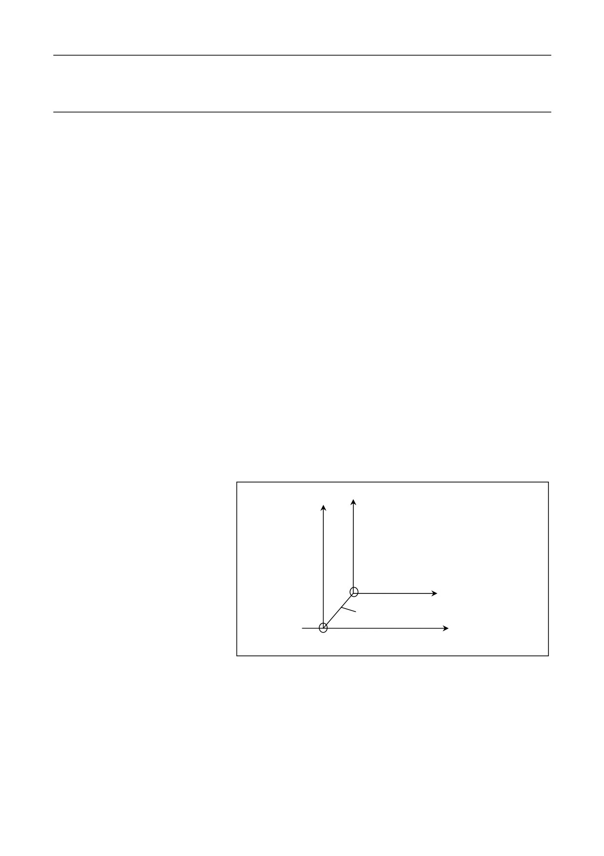
During processing, after the workpiece is installed on the machine with
the clamper, measure the distance between the workpiece origin and the
machine origin (defined by measuring the distance between certain base
level/lines). This distance is called the workpiece origin offset
(the
absolute coordinate value of the machine origin in the workpiece
coordinate system). See the figure below. Before machining, pre-input
the offset value in the CNC system, then during machining, the
workpiece origin offset value is automatically attached to the workpiece
coordinate system, to ensure accurate axis movement on the CNC
machine; therefore, programmers can directly create programs based on
blueprint dimensions, without considering the installation position of the
workpiece on the machine.
Y
Y
Ow Workpiece coordinate system
X
Workpiece origin offset
Y
Machine coordinate system
11
1. Overview
1.6 Programming Origin
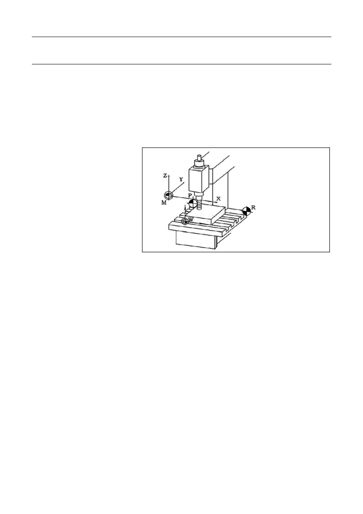
Generally, for simple workpiece, the workpiece origin is the
programming origin. For the workpiece with complex shapes, you need
to create several programs or subprograms. To facilitate programming
and reduce coordinate value calculation, the programming origin will not
be necessarily the workpiece origin, but be defined in a position for easy
programming.
The figure below shows the coordinate systems and relative points.
M: Machine origin
R: Machine reference point
W: Workpiece origin
P: Programming origin
12
1. Overview
1.7
Absolute and Relative Coordinate Systems
There are two modes to describe the amount of movement in the CNC
system: the absolute coordinate system and the relative coordinate
system.
-
The absolute coordinate system refers to the coordinate system
where all coordinate points are measured based on a fixed origin.
-
The relative coordinate system refers to the coordinate system
where the end point coordinates of the motion path are measured
based on the starting point.
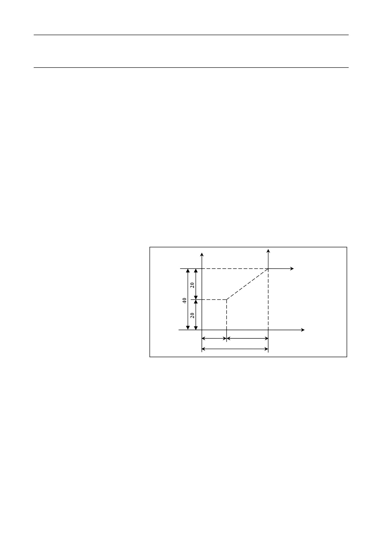
As shown in the figure below, A, B are two coordinate points. In the
absolute coordinate system, the coordinate value of the two points (A, B)
are
(
x
,
)=(
40,40)
and
(
x
,
)=(
15,20)
respectively; but in
A y
A
B y
B
the relative coordinate system with the origin of point A, the coordinate
value of the point B is
(
x
,
)=(
−
25,−20)
B y
B
Y
Y
A
X
B
O
15
25
X
40
13
2. Preparation
2 Preparation (G-Code)
Modal
There are two kinds of G-codes based on their validity:
-
Non-Modal G-code: valid only when the G-code is specified,
invalid when not specified.
-
Modal G-code: saved in the CNC system when it is executed once,
and valid until other codes of the same group is executed
Group
G-codes are divided into several groups according to their functions. 00
group is non-modal G-code and other groups are modal G-code. Multiple
G-codes from different groups can be specified in the same program
block. If multiple G-codes from the same group are specified in the same
block, only the last specified code is valid.
14
2. Preparation
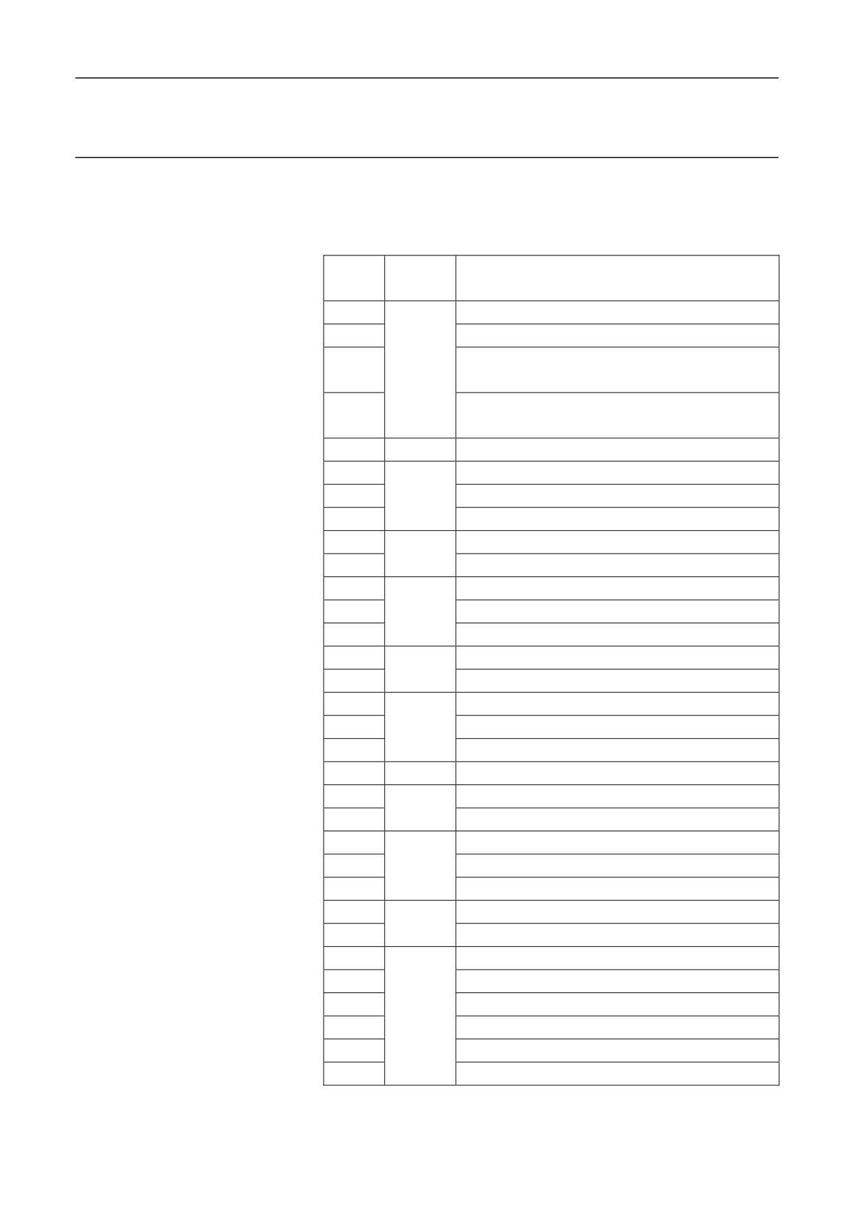
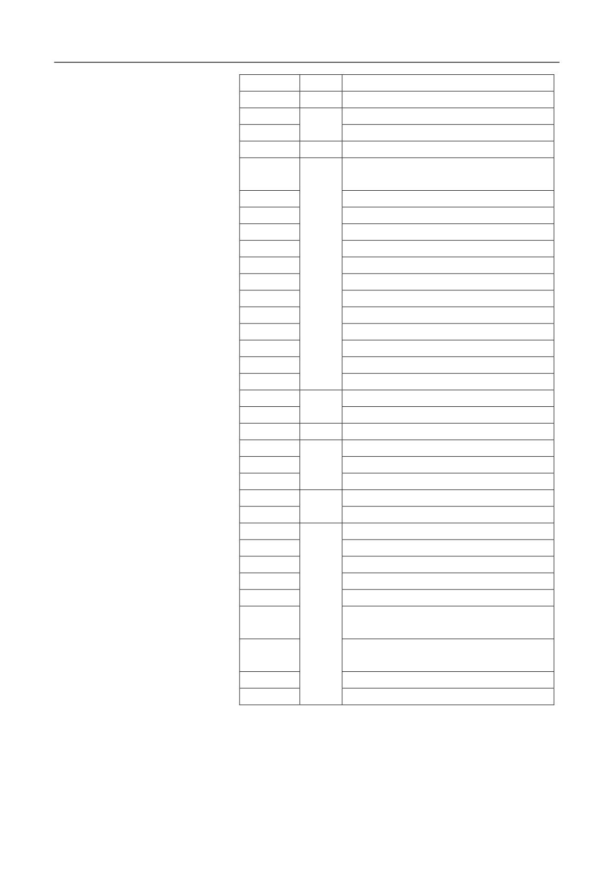
2.1 G-Codes (T)
Attention
After the system is powered on, the G-code marked with the "[ ]" symbol
indicates the initial modal of the same group, while the "『 』" symbol
indicates the equivalent macro name of the G-code.
G
Group
Function
Code
No.
G00
Quick location
[G01]
Linear interpolation
Clockwise (CW) circular interpolation/CW
G02
01
cylindrical helical interpolation
Counter clockwise (CCW) circular interpolation/
G03
CCW cylindrical helical interpolation
G04
00
Pause
G07
Specify the imaginary axis
G08
00
Close look-ahead function
G09
Exact stop verification
G10
Programmable data input
07
[G11]
Cancel programmable data input
G17
XY plane selection
G18
02
ZX plane selection
[G19]
YZ plane selection
G20
Inch input
08
[G21]
Metric input
G28
Return to the reference point
G29
00
Return from the reference point
G30
Return to the reference point 2, 3, 4, and 5
G32
01
Thread cutting
[G36]
Diameter programming
17
G37
Radius programming
[G40]
Cancel tool radius compensation
G41
09
Left cutter compensation
G42
Right cutter compensation
G52
Local coordinate system settings
00
G53
Direct machine coordinate system programming
G54.x
Extended workpiece coordinate system selection
[G54]
Select workpiece coordinate system 1
G55
Select workpiece coordinate system 2
11
G56
Select workpiece coordinate system 3
G57
Select workpiece coordinate system 4
G58
Select workpiece coordinate system 5
15
2. Preparation
G59
11
Select workpiece coordinate system 6
G60
00
Single-orientation
[G61]
Precise stop mode
12
G64
Cutting mode
G65
00
Macro non-modal calling
Inner (outer) diameter roughing compound
G71
cycle
G72
End-face roughing compound cycle
G73
Closed contour compound cycle
G76
Thread cutting compound cycle
G80
Inner (outer) diameter cutting cycle
G81
End-face cutting cycle
06
G82
Thread cutting cycle
G74
End-face deep-hole drilling cycle
G75
Outer diameter grooving cycle
G83
Axial drilling cycle
G87
Radial drilling cycle
G84
Axially rigid tapping cycle
G88
Radial rigid tapping cycle
[G90]
Absolute programming mode
13
G91
Incremental programming mode
G92
00
Workpiece coordinate system settings
G93
Inverse-time feed
[G94]
14
Feed per minute
G95
Feed per revolution
[G97]
Disable constant linear velocity control
19
G96
Enable constant linear velocity control
G101
Axis release
G102
Axis acquisition
G103
Command channel loader
G103.1
Run the command channel loader
G104
Channel synchronization
G108
00
Change the spindle to the C-axis
『STOC』
G109
Change the C-axis to spindle
『CTOS』
G110
Alarm
G115
Redefine the rotary axis angular resolution
16
2. Preparation
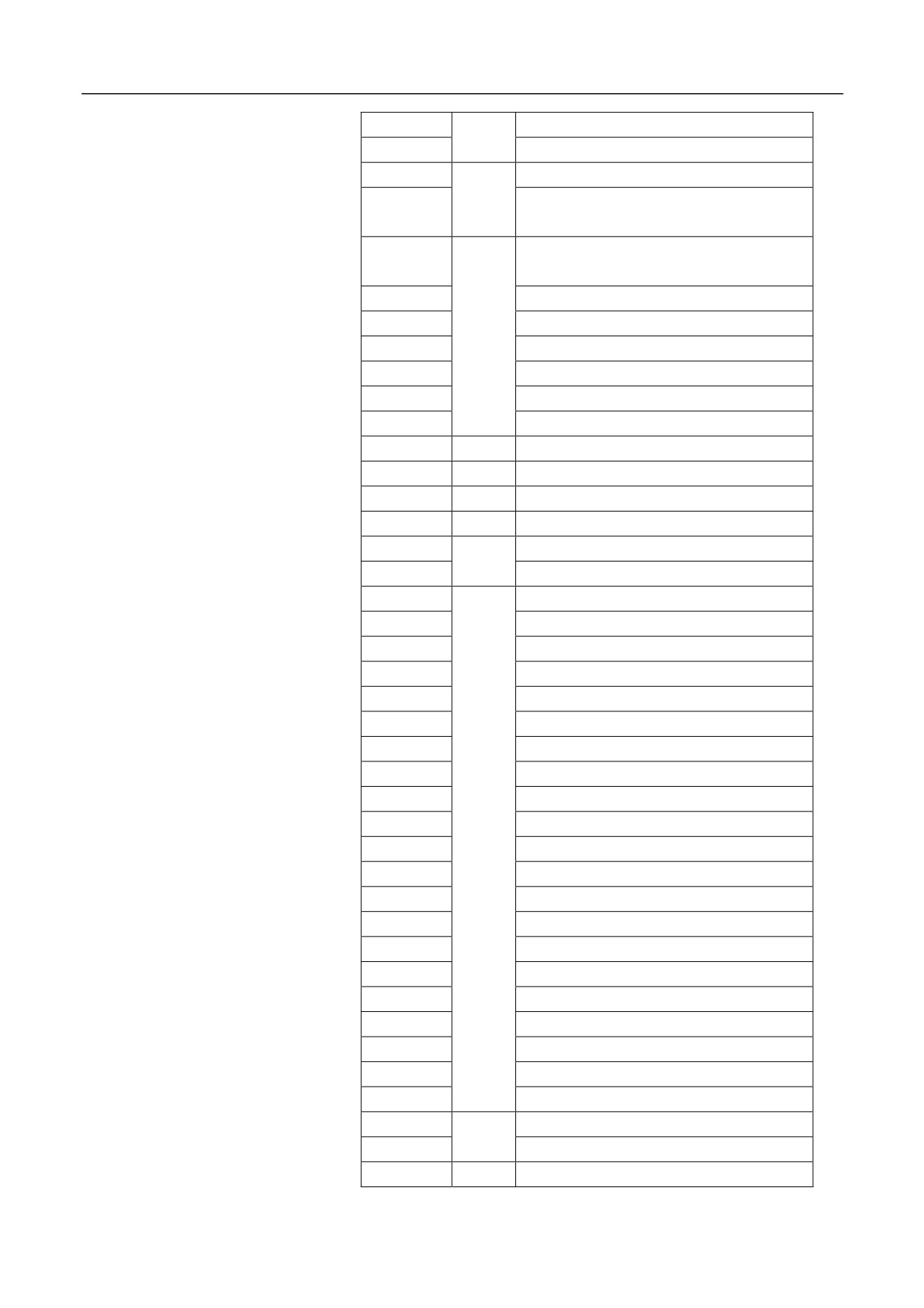
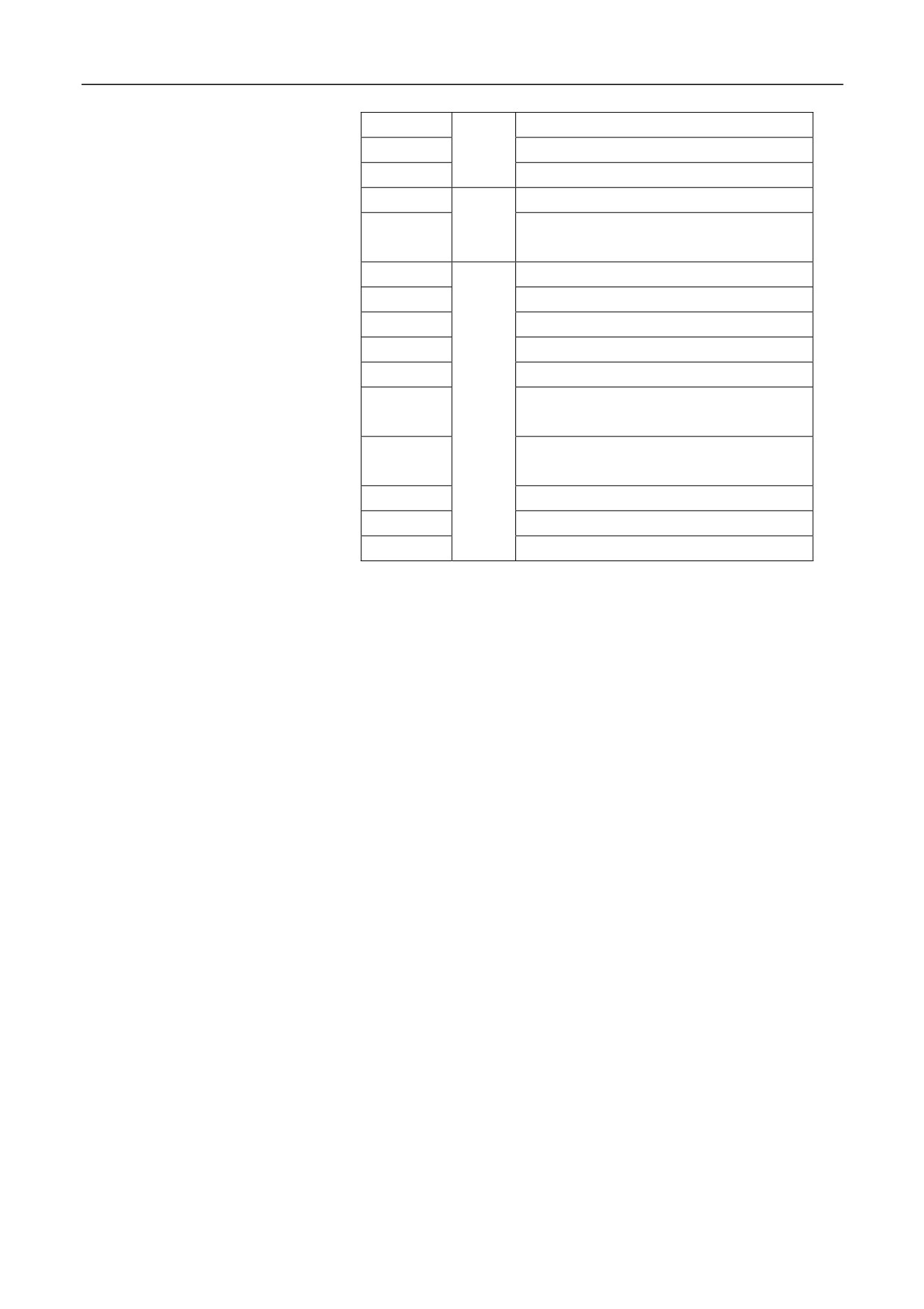
2.2 G-Codes (M)
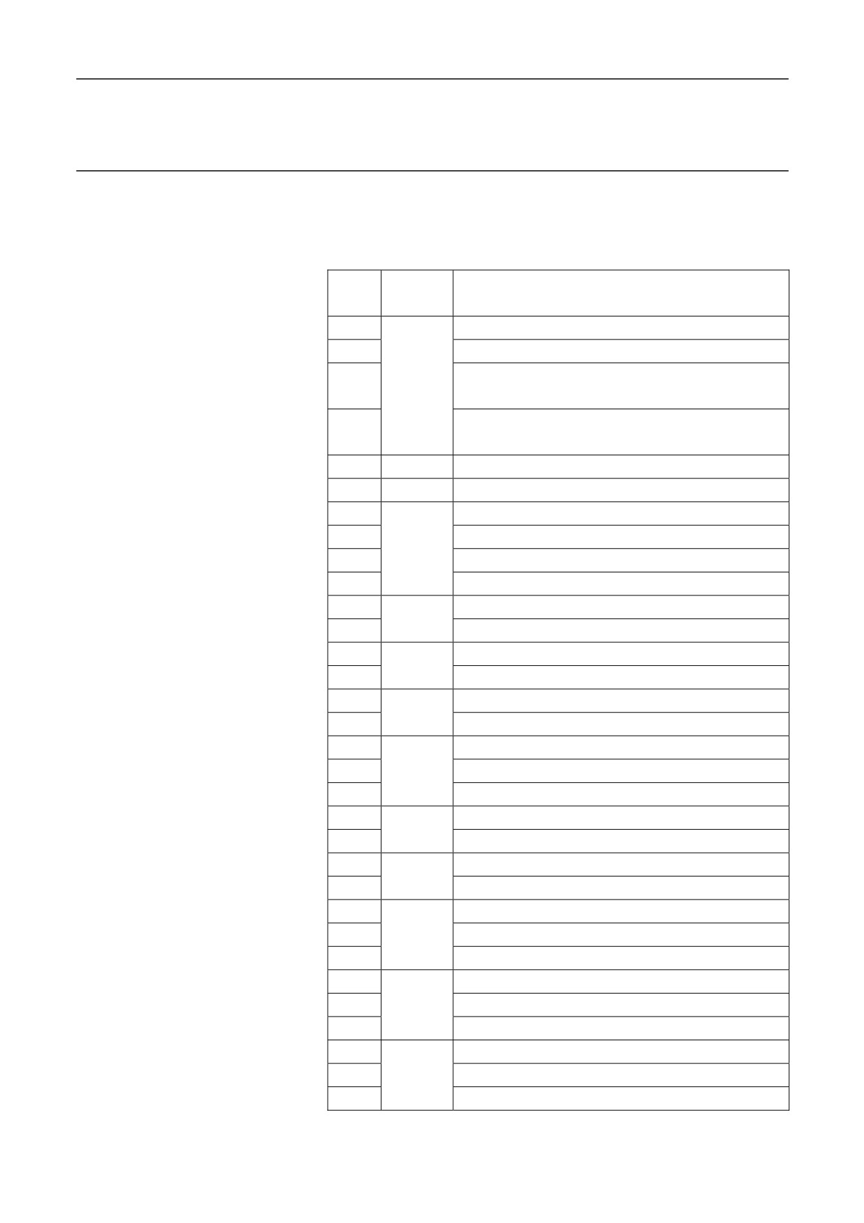
Attention
After the system is powered on, the G-code marked with the "[ ]" symbol
indicates the initial modal of the same group, while the "『 』" symbol
indicates the macro name of the G-code.
G
Group
Function
Code
No.
G00
Quick location
[G01]
Linear interpolation
CW circular interpolation/ CW cylindrical helical
G02
01
interpolation
CCW circular interpolation/ CCW cylindrical
G03
helical interpolation
G04
00
Pause
G05.1
27
High-speed high-precision mode
G07
Specifies the imaginary axis
G07.1
Cylindrical surface interpolation
00
G08
Close look-ahead function
G09
Exact stop verification
G10
Programmable data input
07
[G11]
Cancel programmable data input
G12
Enable polar coordinate interpolation
18
[G13]
Disable polar coordinate interpolation
[G15]
Disable polar coordinate programming
16
G16
Enable polar coordinate programming
[G17]
XY plane selection
G18
02
ZX plane selection
G19
YZ plane selection
G20
Inch input
08
[G21]
Metric input
G24
Enable Mirror function
03
[G25]
Disable Mirror function
G28
Return to the reference point
G29
00
Return from the reference point
G30
Return to the reference points 2, 3, 4, and 5
[G40]
Cancel tool radius compensation
G41
09
Left cutter compensation
G42
Right cutter compensation
G43
Positive tool length compensation
G44
10
Negative tool length compensation
[G49]
Cancel tool length compensation
17
2. Preparation
[G50]
Disable the Zoom function
04
G51
Enable the Zoom function
G52
Local coordinate system setting
00
Direct machine coordinate system
G53
programming
Extended workpiece coordinate system
G54.x
selection
[G54]
Select workpiece coordinate system 1
G55
Select workpiece coordinate system 2
11
G56
Select workpiece coordinate system 3
G57
Select workpiece coordinate system 4
G58
Select workpiece coordinate system 5
G59
Select workpiece coordinate system 6
G60
00
Single-orientation
[G61]
12
Precise stop mode
G64
Cutting mode
G65
00
Macro non-modal calling
G68
Start rotation transformation
05
[G69]
Cancel rotation transformation
G73
Deep-hole drilling cycle
G74
Reverse-tapping cycle
G76
Fine-boring cycle
[G80]
Cancel fixed cycle
G81
Centre-drilling cycle
G82
Drilling cycle with pause
G83
Deep-hole drilling cycle
G84
Tapping cycle
G85
Boring cycle
G86
Boring cycle
G87
06
Anti-boring cycle
G88
Boring cycle (hand boring)
G89
Boring cycle
G181
Arc groove cycle (Type 1)
G182
Arc groove cycle (Type 2)
G183
Circumference groove milling cycle
G184
Rectangular groove cycle
G185
Circular groove cycle
G186
End-face milling cycle
G188
Rectangular boss cycle
G189
Circular boss cycle
[G90]
Absolute programming mode
13
G91
Incremental programming mode
G92
00
Define workpiece coordinate system
18
2. Preparation
G93
Inverse-time feed
[G94]
14
Feed per minute
G95
Feed per revolution
[G98]
Fixed cycle returning to the starting point
15
Fixed cycle returning to the reference
G99
point
G101
Axis release
G102
Axis acquisition
G103
Command channel loader
G103.1
Run the command channel loader
G104
Channel synchronization
G108
00
Change the spindle to the C-axis
『STOC』
G109
Change the C-axis to spindle
『CTOS』
G115
Redefine the rotary axis angular resolution
NURBS
NURBS spline interpolation
HSPLINE
HSPLINE spline interpolation
19
3. Program Structure
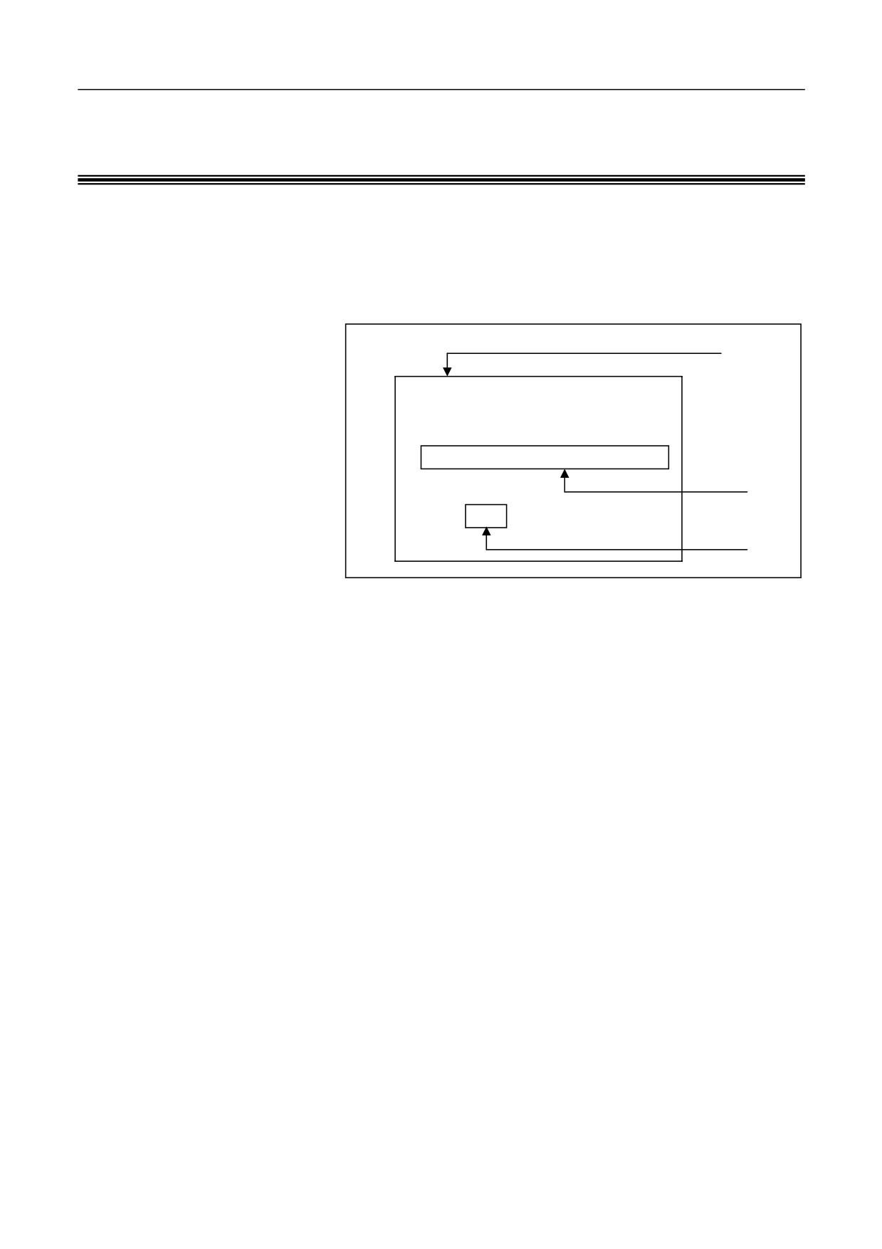
3 Program Structure
A program is a set of commands and data transferred to the CNC system.
A program consists of a number of program blocks which follow a
certain structure, syntax and format rules. Each block consists of a
number of commands. See the figure below:
Program
%1000
N01 G91 G00 X50 Y60
N10 G01 X100 Y500 F150 S300 M03
Block
N
N200
M02
Command
20
3. Program Structure
3.1 Command Format
A command consists of address characters (command word) and digital
numbers with characters (e.g. dimension word) or without characters (e.g.
preparatory function character command: G-code). Example: G01 X100
Z-90
Different commands in the program block may have different meaning in
different environments. For details, see relevant sections in this
documentation.
21
3. Program Structure
3.2 Program Block Format
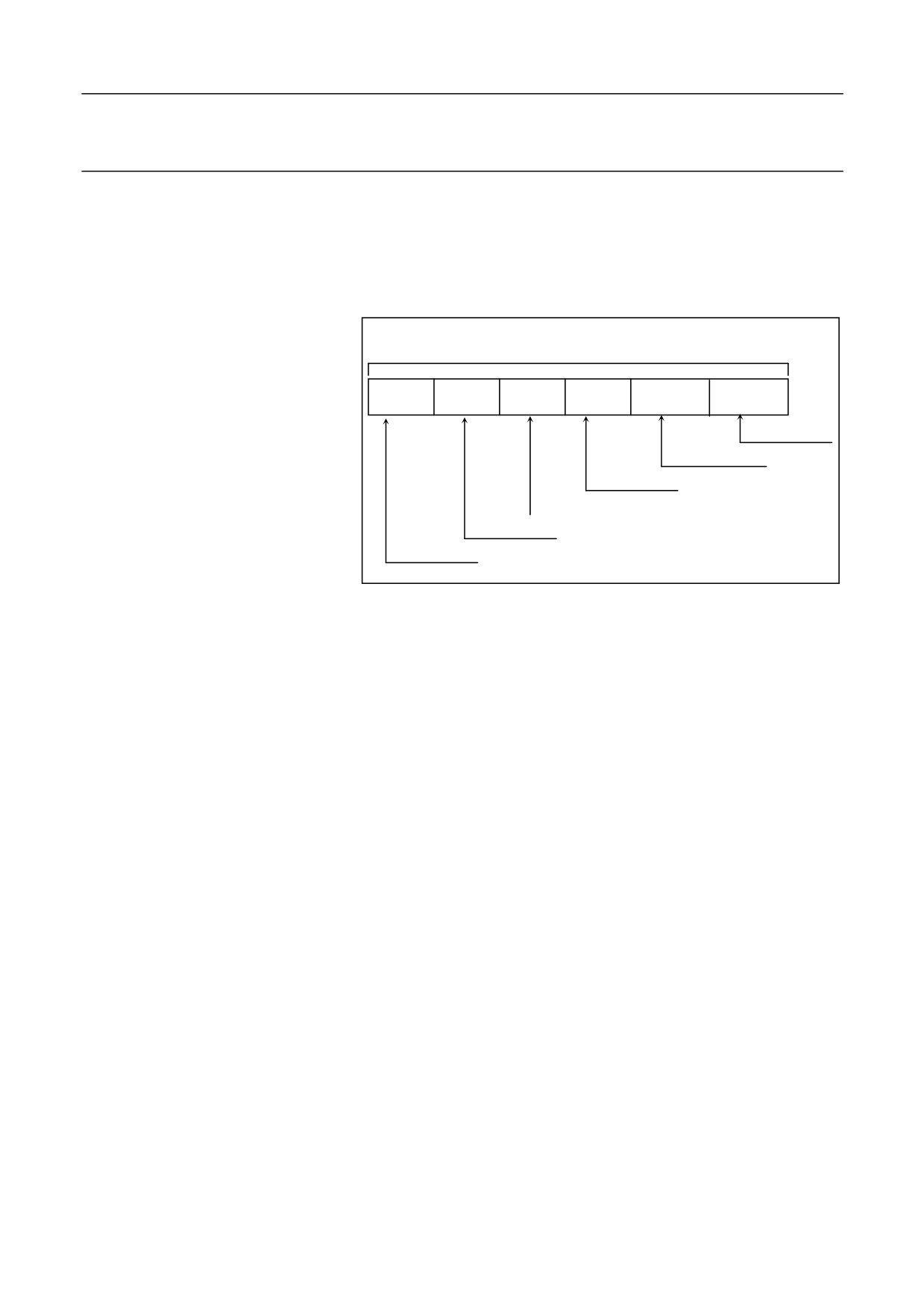
A program block specifies the commands executed by a numerical
control device.
The block format specifies the syntax of the functional words of each
program block. See the figure below:
Block
N..
G..
X..
F..
M..
S..
Spindle Function
Auxiliary Function
Feed Function
Dimension word
Preparatory function
Block number
22
3. Program Structure
3.3 General Program Structure
A program must include the start symbol and end symbol.
A program is executed based on the input order of the blocks, rather than
the order of block numbers. However, when you write a program, it is
recommended to write block numbers in the ascending order.
Start symbol
The symbol "%" (or "O") must be followed by a number (e.g. % 3256).
The program start symbol should be in a separate line, starting at the first
line and first character of the program.
Program end
M02: End the program
M30: End the program and return to the program head
Comment symbol
The content inside "( )" or behind a semicolon symbol (;) is the comment
text. Identify
;and ; .
Single-line command
During G-code programs writing, please be noted that some commands
must be in a separate line. Examples: M30, M02, M99, M6T, CTOS,
STOC, G16, G15, G05.1, G04
23
3. Program Structure
3.4 Program File Name
Many program files can be saved in the CNC device, and can be written
and read in the disk.
File Name
Oxxxxx; "xxxxx" indicates the file name.
The CNC system calls programs by calling the file name, for machining
or editing.
Naming Rules
the file:
-
26 letters, uppercase or lowercase
-
Numbers
The created program file name can contain up to seven characters.
The CNC system may read program files, of which name contains more
than seven characters (created externally).
The CNC system reserves the following file names, which cannot be
specified for naming the program file.
• USERDEF.CYC
• MILLING.CYC
• TURNING.CYC
Use the following characters to name
24
3. Program Structure
3.5 Program File Properties
Access properties of program files can be set.
Editing forbidden
The currently loaded program can be set to Read-only through interface
operation. The file cannot be edited until its property is set to Write
through interface operation.
In addition, you may also control the program accessibility through the
key switch on the project panel. However, the key switch is valid for all
programs in the Program Manager. When the key switch is turned off, all
programs will become read-only until the switch is turned on.
For detailed description of the program file property control, see section
错误!未找到引用源。 in III Operation.
25
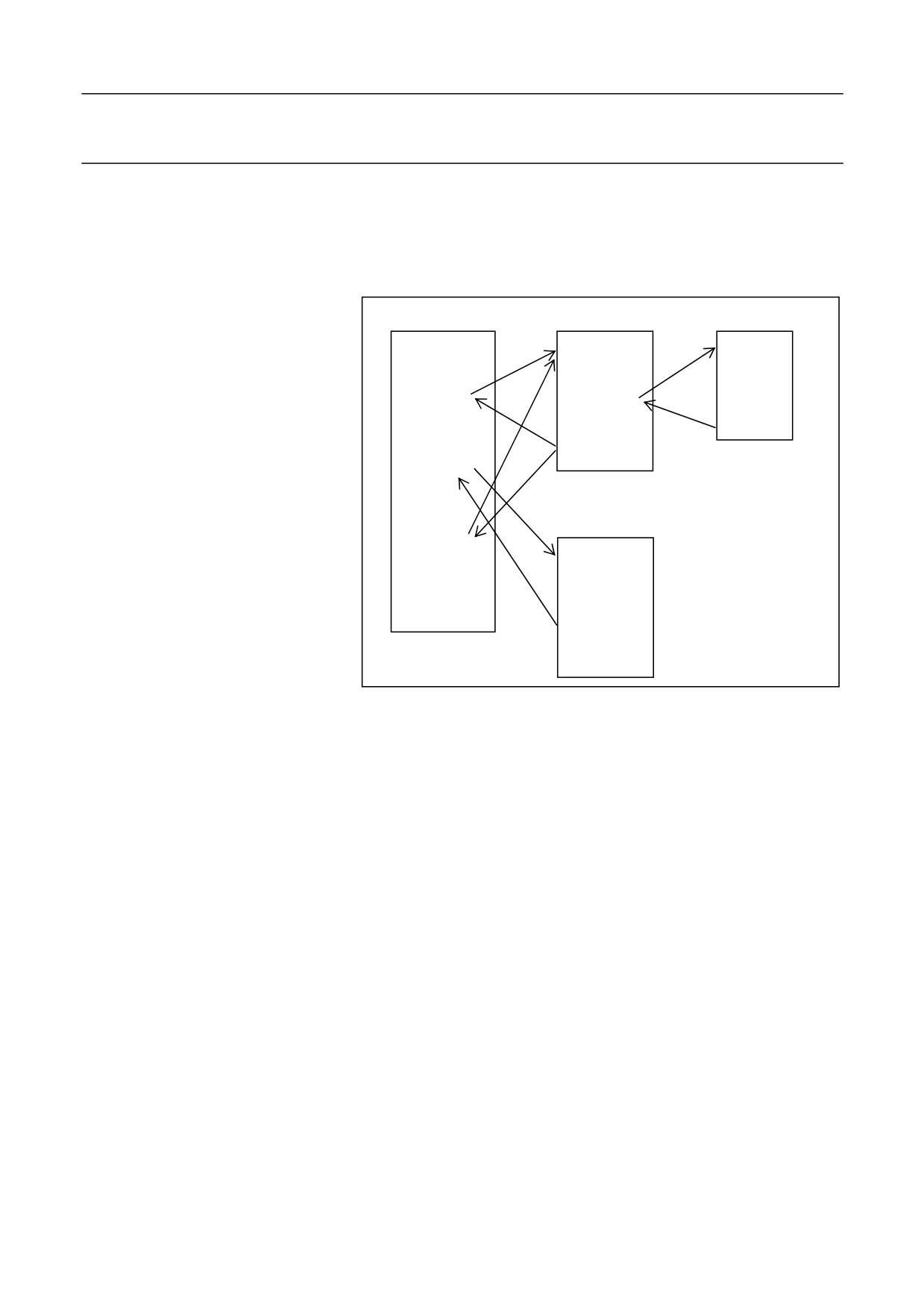
3. Program Structure
3.6 Sub-Programs
When a fixed machining operation is repeated in a program, you may set
it as a sub-program and input it into the program to simplify the
programming.
Execution Process
Main program
Sub-program 1001
Sub-program 1002
%1001;
%1002;
……
……
……
M98P1001;
M98P1002;
……
……
M99;
……
M99;
M98P2001;
……
Sub-program 2001
M98P1001;
%2001;
……
……
……
M30;
M99;
Call Sub-program
You may call a sub-program with M98 or G65. For the method of calling
a sub-program with M98, see the description of M98 in section 4. For the
method of calling a sub-program with G65, see section 13.
26
4. Auxiliary Functions
4 Auxiliary Functions
This chapter includes the following sections:
4.1 M Commands
4.2 S Commands
4.3 T Commands
27
//////////////////////