HNC-818. User Manual - page 2
4. Auxiliary Functions
4.1 M Commands
Auxiliary function commands consist of the address character "M" and
digital numbers. It is used to control the motion of the programs, various
auxiliary switch of the machine, the start and stop of the spindle, end of
the program, etc.
Generally, one program block has only one valid M command. In this
system, up to four M commands can be specified in one block (M
commands in the same group cannot be specified in the same line).
The M commands (M00, M01, M02, M30, and M99) must be in a
separate line. In other words, the program line which contains any of the
M commands mentioned above can contain only one M command, and
cannot have other commands such as G commands or T commands.
The relationship between the M commands and their functions depends
on the specific settings of the machine manufacturer.
Modal
The M functions include non-modal and modal functions:
-
Non-modal M function (valid only in the current block)
-
Modal M function (continuously valid)
Modal Group
Modal M commands are grouped according to different functions. Once
the defined modal M command has been executed, it remains valid until
it is canceled by other modal M commands in the same group.
The Modal M function group contains a default function which is the
initial function when the system is powered on.
Pre- and Post- M functions
The M function can also be divided into pre-M function and post-M
function:
-
Pre-M function
Executed before the axis motion specified by the program block.
-
Post-M function
Executed after the axis motion specified by the program block.
28
4. Auxiliary Functions
4.1.1 Default CNC Auxiliary Functions
M00
Pause Program
When the CNC system executes the M00 command, it will pause the
execution of the current program. That facilitates the operator to carry
out dimensional measurements of the tool and the workpiece, turn
around the workpiece, manually change speed, etc.
When the system pauses the program, the feeding on the machine is
stopped, and all existing modal information remains unchanged. If you
want to continue the follow-up procedures, press the Start button on the
control panel.
M00 indicates the non-modal post-M function.
M01
Optional Pause Program
If you activate the Optional Pause key on the control panel, the CNC
system will pause the current program when it executes the M01
command, to facilitate the operator to carry out dimensional
measurements of the tool and the workpiece, turn around the workpiece,
manually change speed, etc. When the system pauses the program, the
feeding on the machine is stopped, and all existing modal information
remains unchanged. If you want to continue the follow-up procedures,
press the Start button on the control panel.
If you do not activate the Optional Pause key on the control panel, the
CNC system will not pause the current program when it executes the
M01 command.
M01 indicates the non-modal post-M function.
M02
End program
M02 is created in the last program block of the main program.
When the CNC system executes the M02 command, all the spindle, feed,
and coolant functions are stopped and the machining is ended.
After the program is ended by M02, you need to recall the program or
press the Restart key under the auto machining sub menu, and press the
Start button on the control panel if you want to re-execute the program.
M02 indicates the non-modal post-M function.
29
4. Auxiliary Functions
M30
End program and return (valid only when it is in a separate line)
The functions of M30 are similar to those of M02, with an additional
control function of returning to the program header (%).
After the program is ended by M30, you need to repress the Start button
on the control panel if you want to re-execute the program.
M98/M99
Call sub-programs
If the program contains a fixed sequence or frequently repeated pattern,
the sequence or pattern can be stored as a sub-program in the memory to
simplify the programming.
A sub-program can be called for a maximum of 10,000 times (L).
A sub-program can be called from a main program.
In addition, a called sub-program can call another sub-program.
Sub-program structure:
%xxxx; Sub-program number
……; Sub-program content
M99; Sub-program returns
Call sub-program (M98)
M98 PƑƑƑƑ LΔΔΔ
ƑƑƑƑ: The number of the called sub-program
(Arabic
numerals)
ΔΔΔ: The times that the sub-program is called
Call nested sub-programs
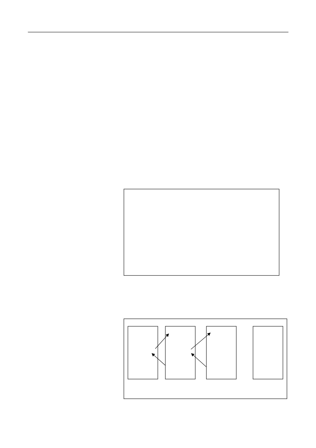
A main program can call up to six levels of sub-programs. See the figure
below:
%1000
%1001
%1002
%1008
…
…
…
…
M98P1001
M98P1002
M98P1003
……
…
…
…
…
M99
M30
M99
M99
30
4. Auxiliary Functions
Execute M99 in a main program
If M99 is executed in a main program, then the system returns to the
header of the main program and re-execute the program.
Use M commands to call sub-programs
Using the M commands to call sub-programs may cause program errors.
You may add G80before M99 to ensure a proper program running. For
details, see section 12.5.
31
4. Auxiliary Functions
4.1.2 Auxiliary Functions Defined by PLC
M3/4/5
Spindle Control
The M03 command starts and rotates the spindle in a clockwise direction
(from the positive direction toward the negative direction of the Z axis)
at the speed specified in the program.
The M04 command starts and rotates the spindle in a counter clockwise
direction at the speed specified in the program.
The M05 command stops the spindle rotation.
The M03 and M04 are modal pre-M functions. M05 is a modal post-M
function, which is the default function.
M03, M04, M05 can be canceled by each other.
M06 Tool Change
M06 is used to call a tool that will be installed on the spindle from the
machining center. The tool will be automatically installed on the spindle
when executing this command. Example: M06 T01 can be used to install
the 01 tool on the spindle.
M06 indicates a non-modal post-M function.
For the machines with armless type ATC, the tool change process is as
follows (e.g. to change the tool 15 on the spindle to tool 01, execute M06
T01.):
1.
Move the spindle quickly to the fixed tool change position which
has been defined by the commissioning personnel.
2.
Directionally rotate the spindle.
3.
Rotate the tool magazine to the position (the position of the tool 15
in Group 0).
4.
The cylinder drives the tool magazine, and chucks the tool on the
spindle.
5.
The cylinder releases the tool on the spindle, and blows to clean the
spindle.
6.
The spindle moves upward, and moves away completely from the
tool.
7.
The tool magazine rotates to the tool position of tool 01(the tool
number of Group 0 in the tool magazine changes to 01).
32
4. Auxiliary Functions
8.
The spindle moves downward, and catches the tool.
9.
The cylinder on the spindle clamps the tool.
10. The tool magazine returns to the original position.
11. Release the orientation of the spindle.
Attention
M06 must be defined in a separate line.
M7/8/9
Coolant Control
M07 and M08 are used to enable the coolant control.
M09 is used to disable the coolant control.
M07 and M08 are modal pre-M functions; M09 is a modal post-M
function, which is the default function.
M64
Workpiece Count
M64 is used to calculate the cumulative count of completed workpiece.
M19/M20
Spindle Orientation
M19 is used for spindle orientation.
M20 is used to cancel the spindle orientation.
M03/M04
The spindle can be switched directly from the position mode to speed
mode by executing the M03/M04 command, without executing G109.
33
4. Auxiliary Functions
4.2 S Commands
Directly Define Spindle Speed
The S command is used to control the spindle rotation speed. The
number that follows S indicates the spindle speed in revolution per
minute (r/min).
The S command is a modal command, and the S function is valid only
when the spindle speed is adjustable.
Define Spindle Speed with Code
In the lathe with mechanical shifting, you may specify a value behind S
to input a code signal to the machine, thereby controlling the spindle
speed of the machine.
This approach needs to be processed in the ladder graph.
34
4. Auxiliary Functions
4.3 T Commands
T commands are used for tool selection. The value that follows T
indicates the selected tool number. The relationship between T
commands and the tool is defined by the machine manufacturer.
machining center to input a code signal or a strobe signal into the
machine, thereby controlling the rotation of the tool magazine to the
Milling System
selected tool, and then wait until the completion of the tool change with
the M06 command. For armless type ATC, the M06 and T commands
must be written in the same block. During tool change, the tool number
(e.g. 15) of Group 0 must be the position of the tool clamped on the
spindle in the tool magazine. When you change the tool to another, you
need to firstly return the tool to the corresponding tool position in the
tool magazine (that is No. 15). Then there should be no tool in the
position of No.15, otherwise a collision may occur. The tools in the tool
magazine are automatically managed by the system, and cannot be
modified. After the machine starts, tool position(e.g. No. 15) facing to
the spindle must be the same as tool number of Group 0 in the tool
magazine, and there should be no tool in the corresponding tool position
(e.g. No. 15).
Therefore, when installing tools to the tool magazine, it is recommended
to firstly install the tool on the spindle, then in the MDI mode, run the M
and T commands (e.g. M06 T01) to install the tool through the spindle.
Execute a T command on the
Turning System
T commands are used for tool selection and tool change. The
four/six/eight digits that follow T indicates the selected tool number and
tool compensation number.
For TXX XX (4 digits), the first two digits indicate the tool number, and
the last two digits indicate the tool compensation number.
For TXXX XXX (6 digits), the first three digits indicate the tool number,
and the last three digits indicate the tool compensation number.
35
4. Auxiliary Functions
For TXXXX XXXS (8 digits), the
first four digits indicate the tool
number, and the last four digits
indicate the tool compensation
number.
The relationship between the tool
You may set parameters to define the number (four by default) of digits
and T commands is specified by the
which follow T code.
machine manufacturer. Please refer
to the user manual of the machine
y When P000061 is set to 2, T code is followed by four digits.
provided by the manufacturer.
y When P000061 is set to 3, T code is followed by six digits.
The same tool may correspond to multiple tool compensations (e.g.
T0101, T0102, T0103), and multiple tools may correspond to the same
tool compensation (e.g. T0101, T0201, T0301).
Execute the T command to rotate the tool turret and select the defined
tool, and at the same time import the tool compensation value(the
geometry compensation value of the tool indicates the offset
compensation plus the wear compensation) in the tool compensation
register. The tool will not move when the T command is executed
without being followed by motion commands.
When a program block contains T commands and tool motion commands
simultaneously, the T commands are firstly executed, and then the tool
motion commands are performed.
%0012
N01 T0101
N02 M03 S460
N03 G00 X45 Z0
N04 G01 X10 F100
N05 G00 X80 Z30
N06 T0202
N07 G00 X40 Z5
N08 G01 Z-20 F100
N09 G00 X80 Z30
M10 M30
For details about the tool compensation, see the relevant tool
compensation section in this documentation.
36
4. Auxiliary Functions
37
5. Interpolation Functions
5 Interpolation Functions
This chapter includes the following sections:
5.1 Linear Feed
5.2 Arc Feed
5.3 Cylindrical Helical Interpolation
5.4 Specify Imaginary Axis
5.5 NURBS Spline Interpolation
5.6 Thread Cutting
5.7 HSPLINE Spline Interpolation
5.8 Jump Function
38
5. Interpolation Functions
5.1 Linear Feed (G01)
G01 enables a linear feed of the tool from the starting point to the end.
Format
Parameter
Description
IP
Under G90command, it indicates the coordinate value of
the end point in the workpiece coordinate system.
G01 IP_ F_
UnderG91command, it indicates the relative
displacement of the end point to the starting point.
Description
F
Feed speed
G01 enables a linear feed of the tool from the current position to the end
point defined by the program block at the speed specified by F and in
linkage approach.
G01 is a modal code, which can be canceled by G00, G02, G03 or G34.
The feed speed specified by F is constantly valid and does not need to be
specified in every program block.
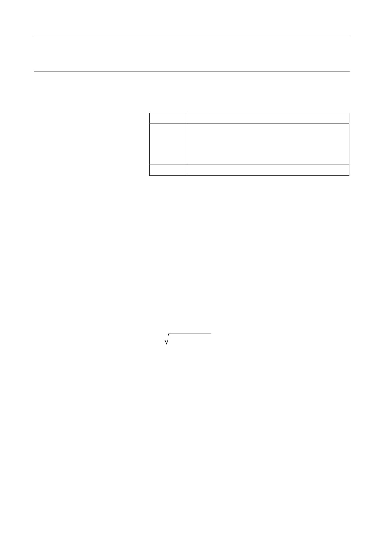
The speed along each axis is as follows:
G91 G01 XĮ Yȕ ZȖ Ff;
X axis: FĮ = Į x f/L;
Y axis: Fȕ = ȕ x f/L;
Z axis: FȖ = Ȗ x f/L;
2
2
2
L=
α
+
β
+
γ
Speed of Rotation Axis
For rotation axis, its feed speed is defined by the linear speed.
During linear interpolation, when the linear axis is Į (e.g. X, unit: mm)
and the rotation axis is ȕ (e.g. C, unit: deg), the tangential speed in the
Į/ȕ Cartesian coordinate system is defined by F (mm/min). The speed on
the ȕ axis is obtained based on the time calculated from the formula
above and then converted to deg/min.
39
5. Interpolation Functions
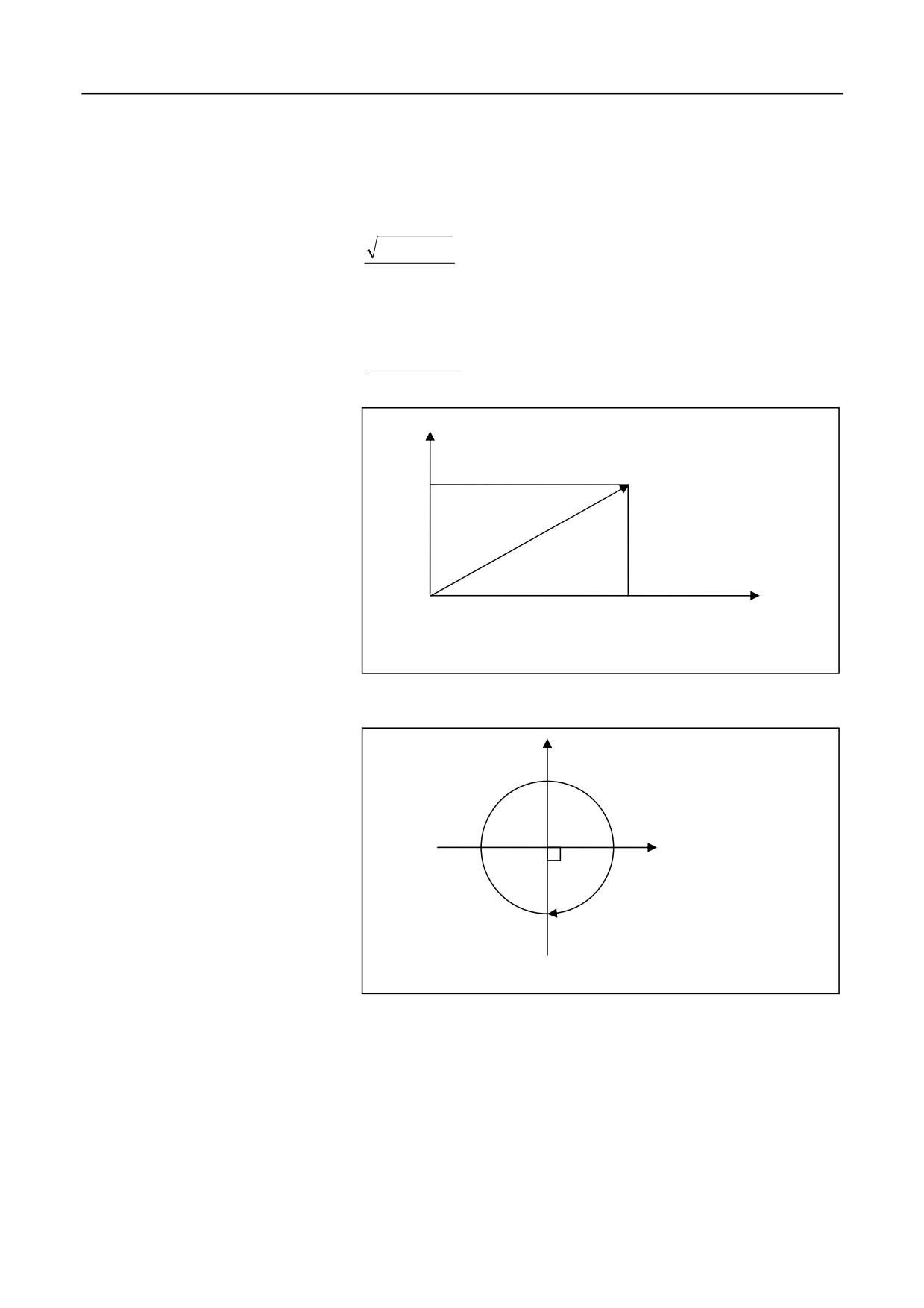
Example: G91 G01 X20.0 C40.0 F300.0;
Assuming the metric input of the C axis 40.0deg is 40 mm
Then the time required should be:
2
20
2 +
40
ؒ0.14907 min
300
The speed on the C axis is:
40 deg
ؒ268.3 deg/min
0.14907 min
Linear Interpolation
Y
Feed speed 300mm/min
End point
200.0
0 (Start point)
300.0
X
G91 G01 X300.0 Y200.0 F300
Rotation Interpolation
Start point
90
Feed speed 300 degree/min
End point
G91 G01 C-90 F300
40
5. Interpolation Functions
After the five-axis RTCP function is enabled, F specifies the movement
speed of the tool center point in the workpiece coordinate system. During
Attention
the five-axis machining, due to the join of the rotation axis, the
movement speed of the tool center point may not match the actual
machine movement speed; therefore, the split-axis speed may exceed the
specified maximum speed limit. In this case, the CNC system will reduce
the machining speed to ensure the split-axis speed within the defined
range.
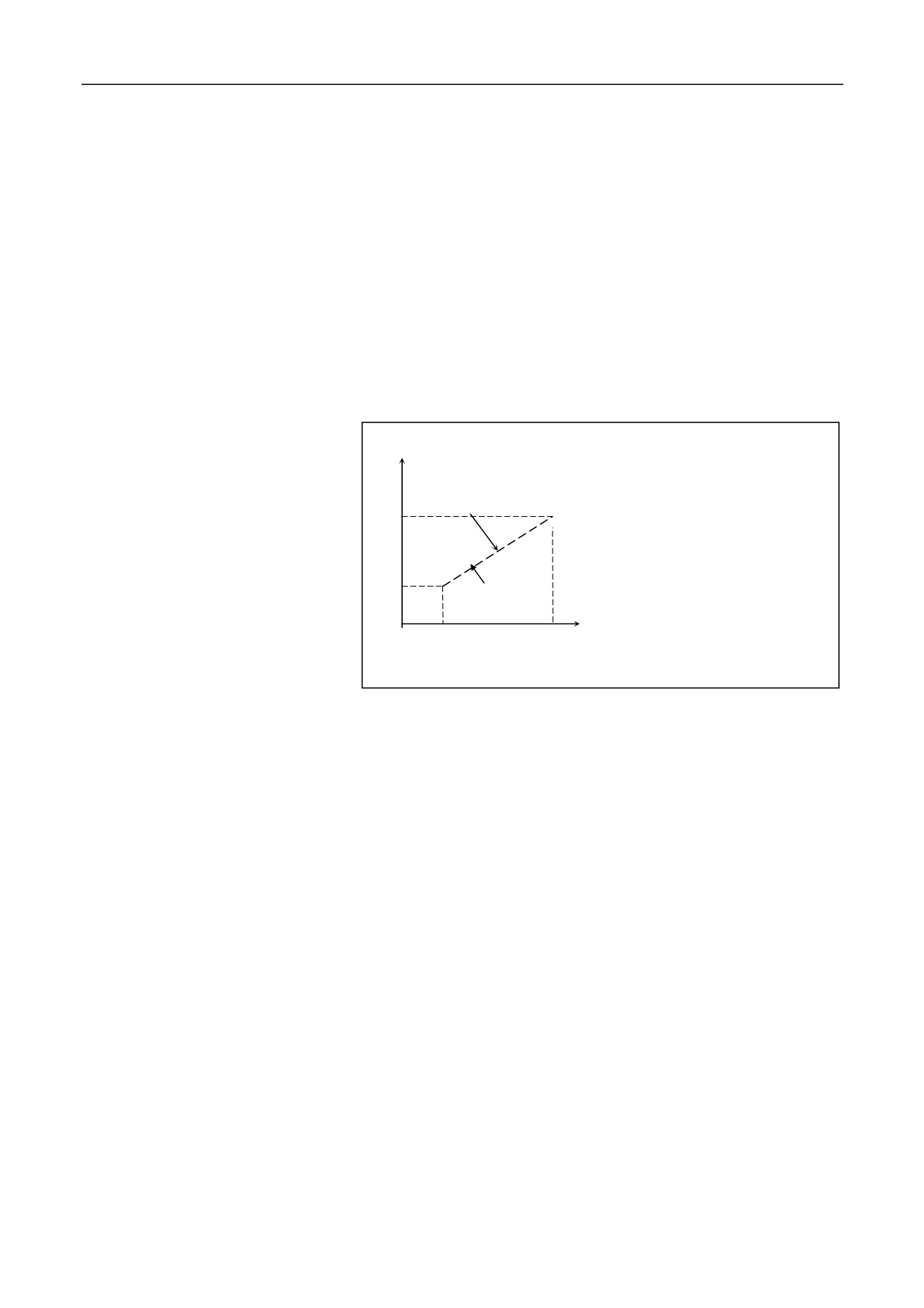
Use G01 for programming: Linear feed from the point A to B (a straight
line from A to B)
Example
Y
Linear feed from A to B
Actual path
Absolute programming:
45
B
G90 G01 X90 Y45 F800
A
15
Incremental programming:
Programming path
X
G91 G01 X70 Y30 F800
O
20
90
41
5. Interpolation Functions
5.2 Arc Feed (G02, G03)
Run the tool to the end along the specified arc direction at a specified
plane (G17, G18, G19).
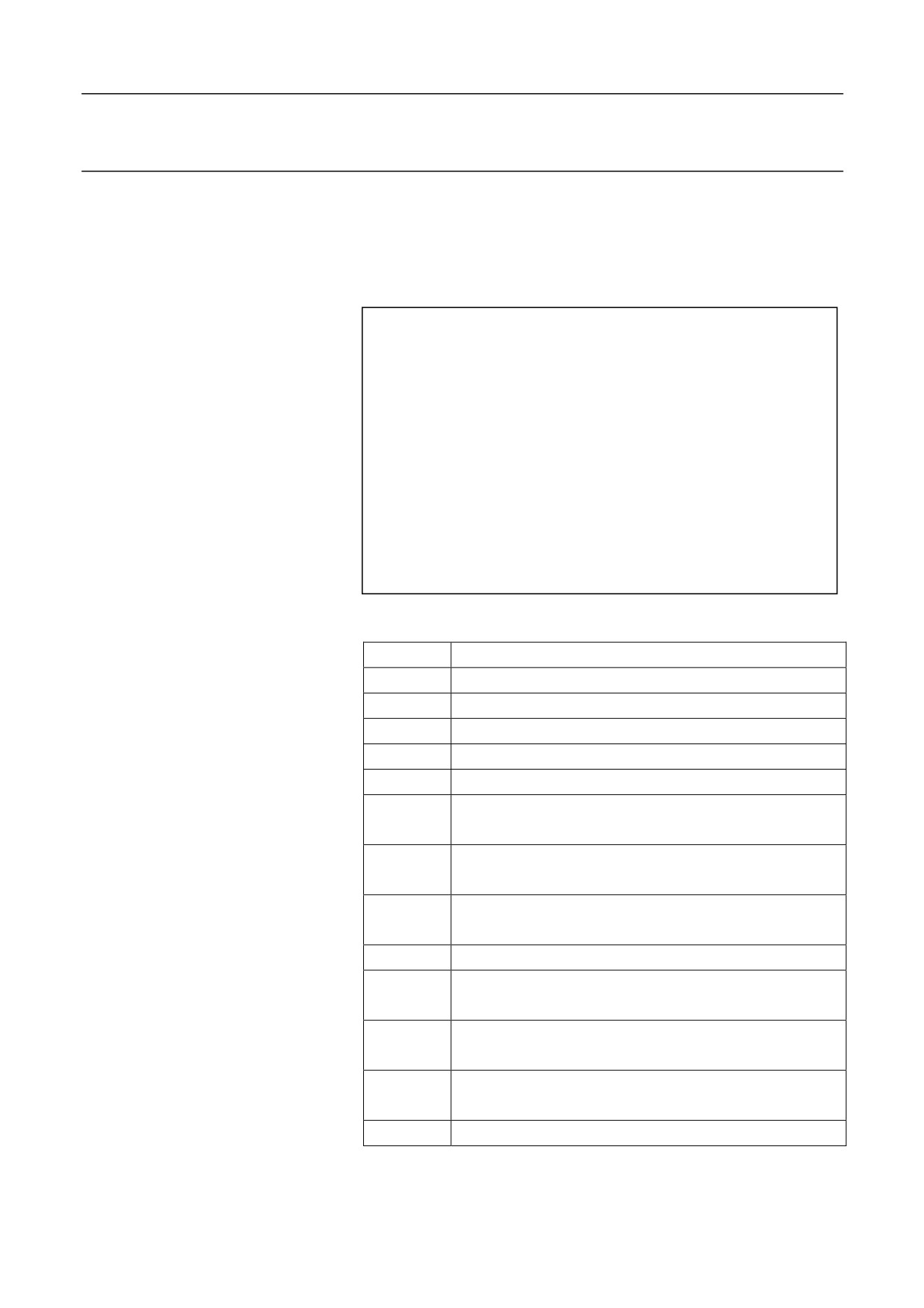
Format
⎧G02⎫
⎧I
_
J
_⎫
G17
X
_Y
F
_
Arc interpolation in the XY
⎨
⎬
⎨
⎬
⎩G03⎭
⎩
R_
⎭
plane
⎧G02⎫
⎧I
_
K
_⎫
G18⎨
⎬X
_Z⎨
⎬F
_
Arc interpolation in the ZX plane
⎩G03⎭
⎩
R_
⎭
⎧G02⎫
⎧J
_
K
_⎫
G19⎨
⎬Y
_
Z⎨
⎬F
_
Arc interpolation in the YZ plane
G03
R_
⎩
⎭
⎩
⎭
Parameter Description
Parameter
Description
G17
Specify arc interpolation at the XY plane
G18
Specify arc interpolation at the ZX plane
G19
Specify arc interpolation at the YZ plane
G02
CW arc interpolation
G03
CCW arc interpolation
X
The amount of movement along the X-axis with arc
interpolation or the X-axis coordinate value of the arc end
Y
The amount of movement along the Y-axis with arc
interpolation or the Y-axis coordinate value of the arc end
Z
The amount of movement along the Z-axis with arc
interpolation or the Z-axis coordinate value of the arc end
R
Arc radius (with signal, "+": inferior arc; "-": excellent arc)
I
The distance from the arc start point along the X-axis to the
center of the arc (with signal)
J
The distance from the arc start point along the Y-axis to the
center of the arc (with signal)
K
The distance from the arc start point along the Z-axis to the
center of the arc (with signal)
F
Feed speed, valid in the modal mode
42
5. Interpolation Functions
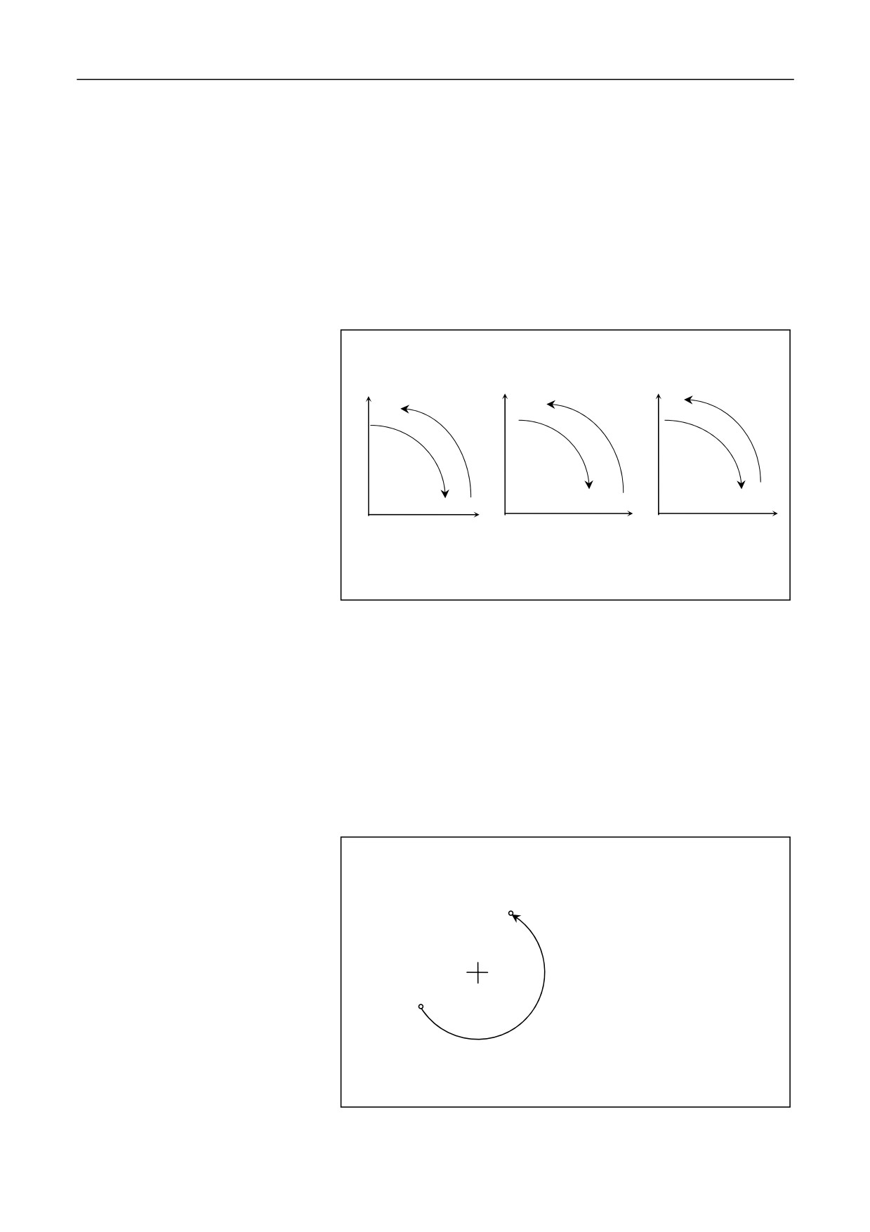
Arc Interpolation Direction
Definition of clockwise (CW) and counter clockwise (CCW) direction in
each plane: in the Cartesian coordinate system, looking to the XY plane
from the positive direction of Z-axis to the negative direction to define
the CW and CCW direction of the XY plane; similarly, looking to the ZX
plane from the positive direction of the Y-axis to the negative direction to
define the CW and CCW direction of the ZX plane; looking to the YZ
plane from the positive direction of the X-axis to the negative direction
to define the CW and CCW direction of the YZ plane. See the figure
below:
Y
X
Z
G03
G03
G03
G02
G02
G02
G17
X
G18
Z
G19
Y
Arc End
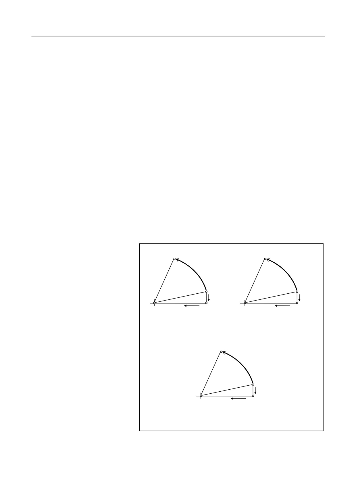
Use the position command (X, Y, Z) to specify the arc end.
In the absolute value (G90) mode, the position command (X, Y, Z)
specifies the absolute position of the arc end point; in the incremental
value (G91) mode, the position command (X, Y, Z) specified the distance
from the arc start point to the end point. See the figure below:
End point
End point of Arc:
(X2, Y2)
G90: X_=X2
Y_=Y2
Start point
G91: X_=X2-X1
(X1, Y1)
Y_=Y2-Y1
43
5. Interpolation Functions
UVW Programming
In addition to the position command (X, Y, Z), you may use the UVW
command to specify the arc end.
For the turning CNC system (T Series), when the channel parameter
Enable Programming with UVW (040033) is set to 1, you may use
UVW instead of XYZ to represent the movement amount (increment) of
G02/G03 along the XYZ axis, or use XYZ and UVW for one
programming.
Note: Only when the UVW axes are not specified as the motion axis, can
UVW be used to specify the arc end.
Distance from the Start Point to
Use the command (I, J, K) to specify the position of the arc center.
the Arc Center
The parameters (I, J, K) indicate the vector components from the start
point to the arc center, and it is always incremental value for both G90
and G91.
You need to specify the positive ("+") or negative symbol ("-") for the
parameters (I, J, K) based on the direction.
See the figure below:
End point (X2, Y2)
End point (Z2, X2)
Start point
Start point
(X1, Y1)
(Z1, X1)
J
I
Center (X0, Y0)
I
Center (Z0, X0)
K
I_=X0-X1
K_=Z0-Z1
G17
G18
J_=Y0-Y1
I _=X0-X1
End point (Y2, Z2)
Start point
(Y1, Z1)
K
Center (Y0, Z0)
J
J_=Y0-Y1
G19
K_=Z0-Z1
44
5. Interpolation Functions
Circular Programming
If the position commands (X, Y, Z) are all left blank during programming,
the start point overlaps the end point. In this case, the command (I, J, K)
specifies a full circle. If R is used to specify the arc, it becomes an arc of
zero degree. A system alarm will be reported.
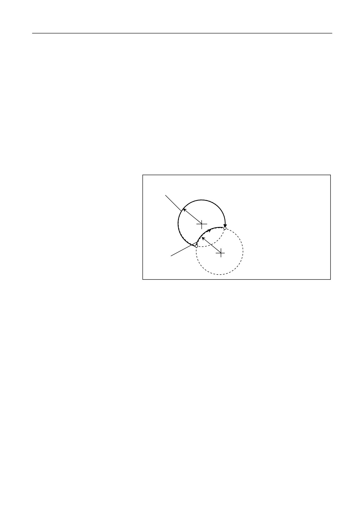
Arc radius
In addition to the command (I, J, K) mentioned above, you may specify
the arc center by using the arc radius. The arc is divided into two types:
1.
Central angle less than 180 degrees
2.
Central angle larger than 180 degrees
Therefore, you need know which arc to be programmed. The two types
can be defined by the positive or negative symbols ("+" or "-") of the arc
radius (R). See the figure below:
Central angle > 180 degrees
Arc1 (Central angle < 180 degrees)
2
G91 G02 X70 Y80 R50 F500;
End point
1
Arc2 (Central angle > 180 degrees)
G91 G02 X70 Y80 R-50 F500;
Start point
Central angle < 180
degrees
Attention
y
y Parameters related to arc interpolation
If the radius difference between the arc start point and end point is
greater than the value specified by CIR INTERPOLATION
C-TOL(mm) (000010), or (radius difference between the arc start
point and end point)
/actual radius is greater than the value
specified by Arc ARC PROG POINT RADIUS TOL(mm)
(000011), the system will alarm.
y I/J/K and R are specified simultaneously
If "I, J, K" and "R" are simultaneously specified in a non-full
circular arc interpolation command, the arc defined by R is valid.
y Specify axis outside the defined plane
If the axis is specified outside the defined plane, an alarm will be
reported.
y
45
5. Interpolation Functions
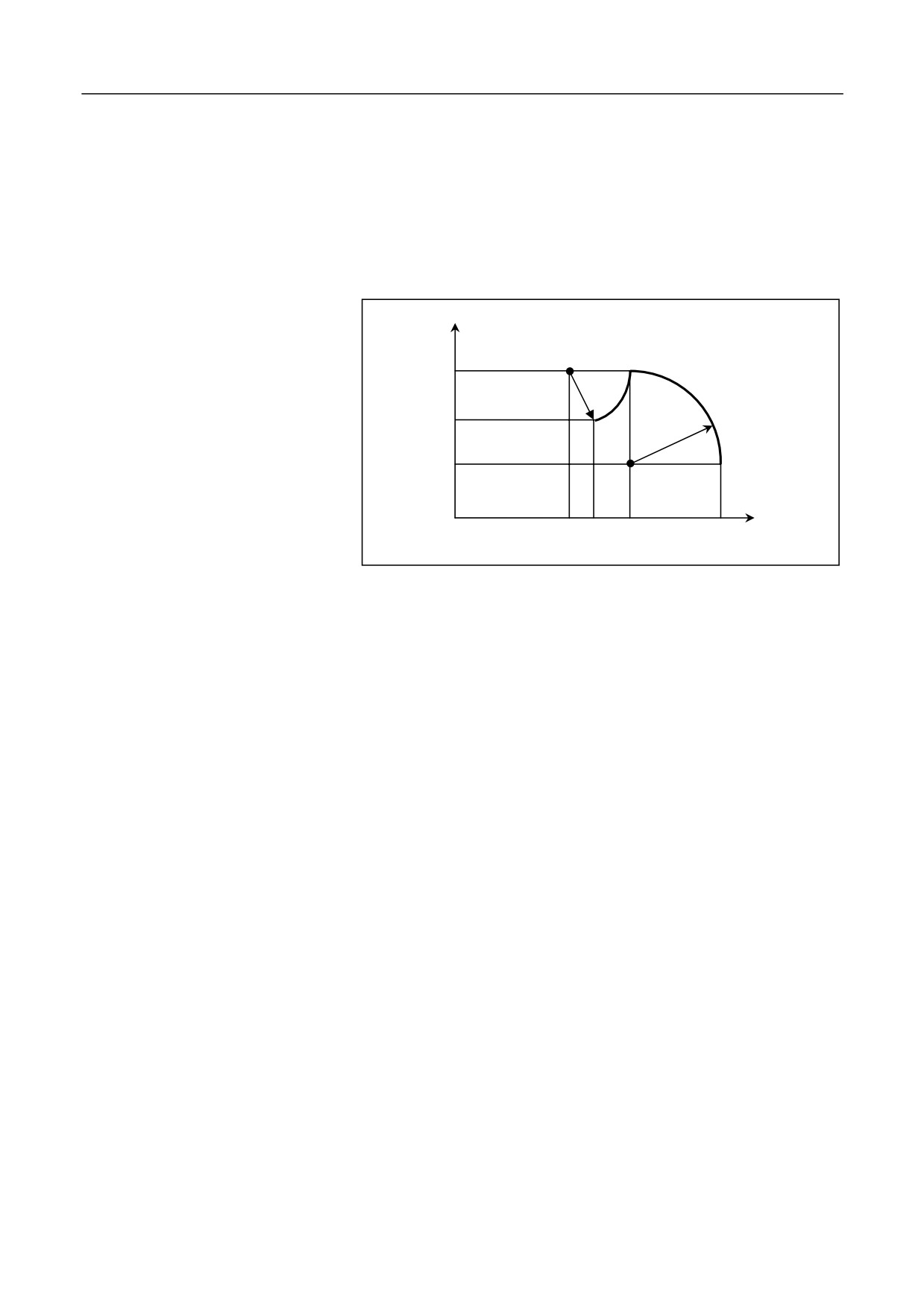
y
Semicircle Programming
When the arc is a semicircle or the central angle is close to 180
degrees, you must use I, J, K to specify the arc center, because a
calculation error may be generated due to the rounding errors if you
use R to specify the arc center.
Example
Y
100
R50
60
End point
R60
40
Start point
0
90
120
140
200
X
As shown in the figure above, the tool path programming is as follows:
1.
Absolute programming
G92 X200.0 Y40.0 Z0;
G90 G03 X140.0 Y100.0 R60.0 F300.;
G02 X120.0 Y60.0 R50.0;
Or
G92 X200.0 Y40.0Z0;
G90 G03 X140.0 Y100.0 I-60.0 F300.;
G02 X120.0 Y60.0 I-50.0;
2.
Incremental programming
G91 G03 X-60.0 Y60.0 R60.0 F3000.;
G02 X-20.0 Y-40.0 R50.0;
Or
G91 G03 X-60.0 Y60.0 I-60.0 F300.;
G02 X-20.0 Y-40.0 I-50.0
46
5. Interpolation Functions
5.3 Cylindrical Helical Interpolation (G02, G03)
In addition to arc interpolation, the G02 and G03 commands can also be
used to define helical interpolation by specifying the movement distance
of the third axis.
Format
⎧G02⎫
⎧I
_
J
_⎫
XY Plane Helical Interpolation
G17⎨
⎬X
_Y
_
Z⎨
⎬F
_
⎩G03⎭
⎩
L_
⎭
⎧G02⎫
⎧I
_
K
_⎫
G18
X
_
Z
_Y
F
_
ZX Plane Helical Interpolation
⎨
⎬
⎨
⎬
G03
L_
⎩
⎭
⎩
⎭
⎧G02⎫
⎧J
_
K
_⎫
G19
Y
_
Z
_
X
F
_
YZ Plane Helical Interpolation
⎨
⎬
⎨
⎬
⎩G03⎭
⎩
L_
⎭
Parameter Description
G17
Specify arc interpolation at the XY plane
G18
Specify arc interpolation at the ZX plane
G19
Specify arc interpolation at the YZ plane
G02
CW arc interpolation
G03
CCW arc interpolation
X
The amount of movement along the X-axis with arc
interpolation or the X-axis coordinate value of the arc
end
Y
The amount of movement along the Y-axis with arc
interpolation or the Y-axis coordinate value of the arc
end
Z
The Z-axis coordinate value in absolute programming, or
the the Z-axis increment of the end point relative the
start point(even if L command is programmed)
R
Arc radius (with signal: "+": inferior arc; "-": excellent
arc)
I
The distance from the arc start point along the X-axis to
the center of the arc (with signal). The value of height
variation for a spiral circle at YZ plane in conic
interpolation.
J
The distance from the arc start point along the Y-axis to
the center of the arc (with signal)
Parameter
Description
47
5. Interpolation Functions
K
The distance from the arc start point along the Z-axis to
the center of the arc (with signal).
F
Feed speed, valid in the modal mode
L
Helical rotation number (positive number without a
decimal point)
For the rotation direction of helical interpolation, refer to the arc
Rotation Direction
direction projected on a two-dimensional plane.
Circular Programming
If the position commands (X, Y, Z) are all left blank during programming,
the start point overlaps the end point. In this case, the command (I, J, K)
specifies a full circle. If R is used to specify the arc, it becomes an arc of
zero degree. A system alarm will be reported.
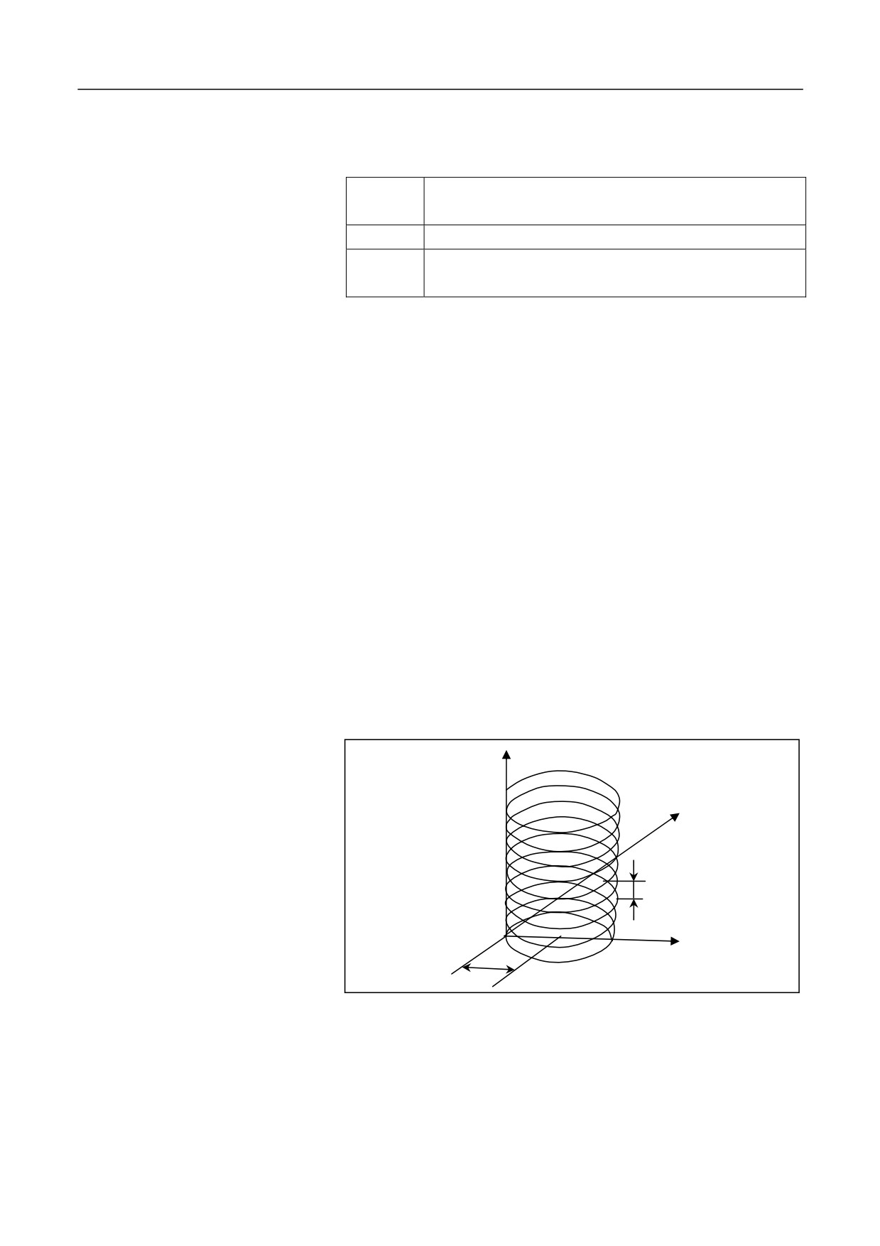
Example
The figure below shows the helical machining:
Z
50
Y
K=5
O
X
15
1.
Absolute programming
X30 Y0 Z0
G90 G03 X0 Y0 Z50 I-15 J0 K0 L10 F3500
48
5. Interpolation Functions
M30
2.
Incremental programming
G91 G03 X-30 Y0 Z50 I-15 J0 K0 L10 F3500
X30 Y0 Z0
M30
49
5. Interpolation Functions
5.4 Specify Imaginary Axis and Sine Interpolation (G07)
Format
G07 IP_
Parameter
Description
IP
Specify axis:
y
0: imaginary axis
y
1: real axis
Description
If an axis is specified as an imaginary axis, this axis is only used for
interpolation calculation without any motion. For example, if the G07 X0
command specifies the X axis as the imaginary axis, then the X axis will
not move until the G07 X1 command is executed.
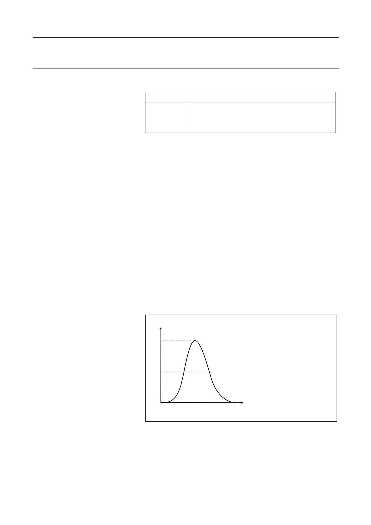
Sine Interpolation
G07 can be used for a sine interpolation. For example, before the helical
interpolation, if an axis used for arc interpolation is specified as the
imaginary axis, then the helical interpolation becomes the sine
interpolation.
Attention
If you want to cancel the imaginary axis specification, you only specify
the imaginary axis as a real axis, e.g. executing G07 X1.
Example
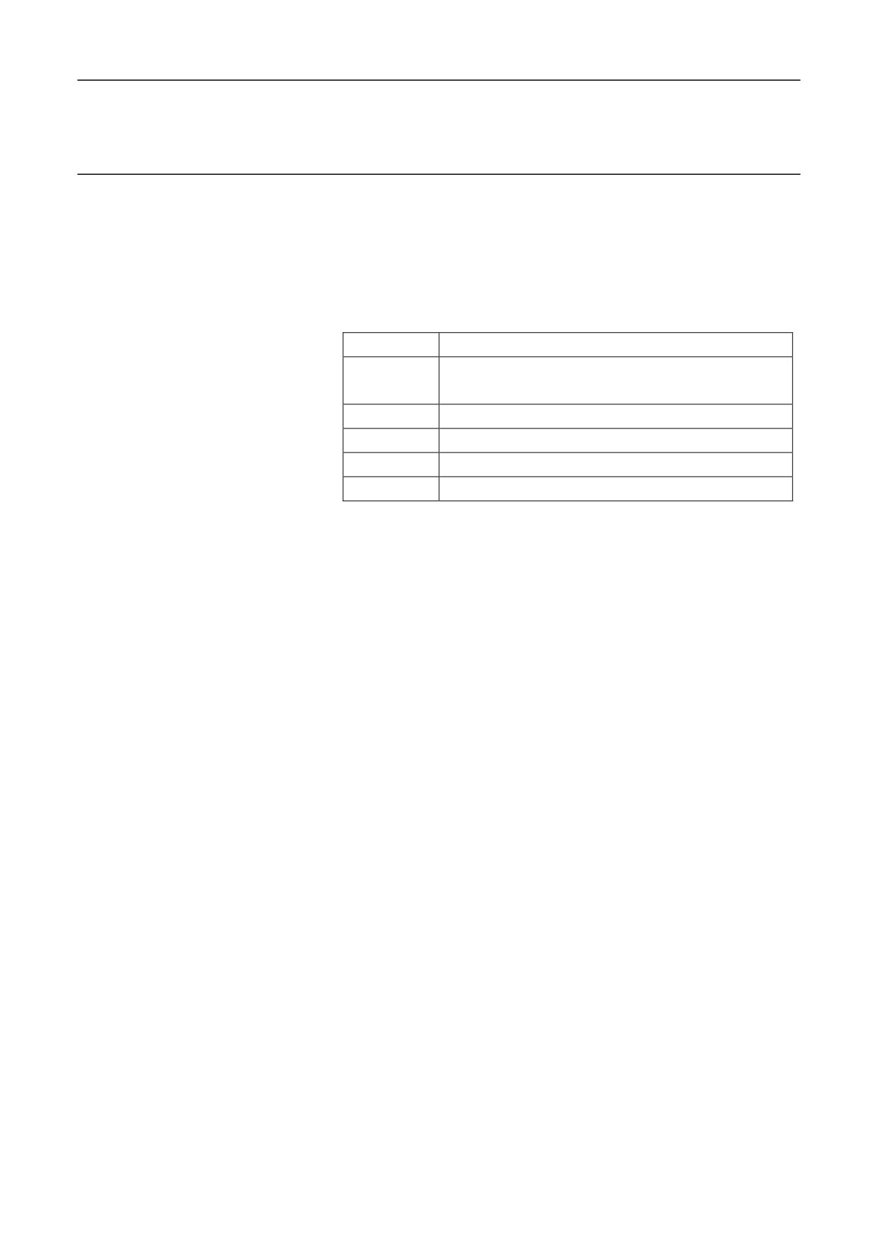
Use G03 for programming the sine curve as below:
Y
…
100
M3S1000
G90 G00 X-50 Y0 Z0
50
G07 X0 G91
G03 X0 Y0 I0 J50 Z60 F800
Z
O
60
…
50
5. Interpolation Functions
5.5 NURBS Spline Interpolation (NURBS)
You may conduct NURBS spline interpolation by specifying three
parameters (IP, W, K) of the NURBS curve.
Single Spline NURBS Format
NURBS P_ K_ IP_ W_ F_;
Parameter
Description
P
Order of NURBS curve; Only cubic spline
interpolation is supported, where the value of P is 4.
K
Node
IP
Control point coordinate
W
Weight
F
Feed speed
Cancel Interpolation
NURBS indicates modal of Group 01. You may cancel the NURBS
interpolation modal by specifying G01 or G00.
Curve order
P is used to specify the order of the NURRBS curve:
P=4, indicates cubic NURBS curve;
P is modal address word, which will be valid until it is changed or other
modal commands in group 01 are specified.
Node
During NURBS interpolation, you must specify the first control point as
the start point and the last control point as the end point.
In addition, use the following format to specify the node of the first
program block:
y Single-spline:
NURBS P4 K:0,0,0,0,1: X1 Y0 Z0
y Dual-spline:
NURBSB P4 K:0,0,0,0,0.5: Q:10,0,0,38.28,0,28.28: W1F60
51
5. Interpolation Functions
Weight
Weight indicates the weight value of the control point specified in the
same program block. If it is not specified, the default value is 1.0.
Compensation
In the NURBS curve interpolation mode, you cannot use tool radius
compensation.
Description
Single-spline NURBS interpolation is generally used for three-axis small
line interpolation.
Dual- spline NURBS interpolation is generally used for five-axis small
line interpolation.
Example
of
Single-spline
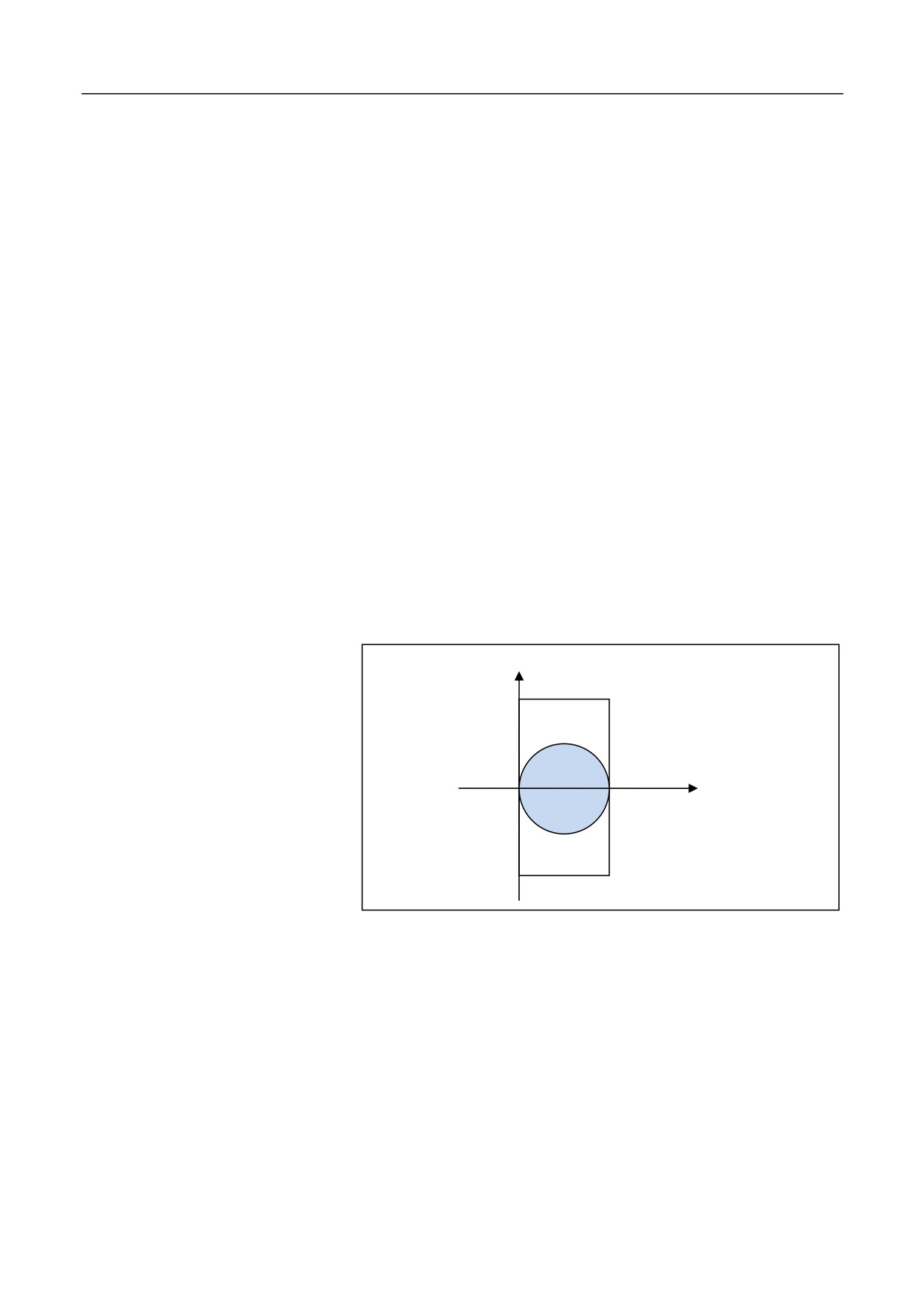
interpolation
The figure below shows the single-spline NURBS interpolation for a
full-circle (R=50mm):
Y
100
(100, 100)
X
-100
(100, -100)
%0001
G54
G90G17F500G64
G01x0y0z0
NURBS P4 K:0.0,0.0,0.0,0.0,0.5: X0.0Y0.0Z0.0 W1.0
K0.5
X0.0000 Y100.0 W0.3333
K0.5
X100.0 Y100.0 W0.3333
52
5. Interpolation Functions
K1.0
X100.0 Y0.0
W1.0
K1.0
X0.0
Y-100
W0.3333
K1.0
X100
Y-100.0
K1.0
X0.0
Y0.0
W1.0
W0.3333
M30
53
5. Interpolation Functions
5.6 Thread Cutting (G32)
The feed operation coincides with the spindle rotation, which different
kinds of threads can be processed, such as variable pitch screw,
multi-thread, etc.
Format
G32 X_ Z_ F_ P_ R_ E_
Parameter
Description
X Z
Thread end point coordinate (G90).
Relative distance of the thread end point away from
the start point (G91).
F
Metric thread pitch (along the long axis).
P
Angle of the thread start point
R
Specify the retreat of tailstock along the Z axis in the
incremental mode. If the tool withdrawal groove is
not required, the parameter signal cannot be specified.
E
Specify the retreat of tailstock along the X axis in the
incremental mode. If the tool withdrawal groove is
not required, the parameter signal cannot be specified.
Constant Pitch
Multi-Thread
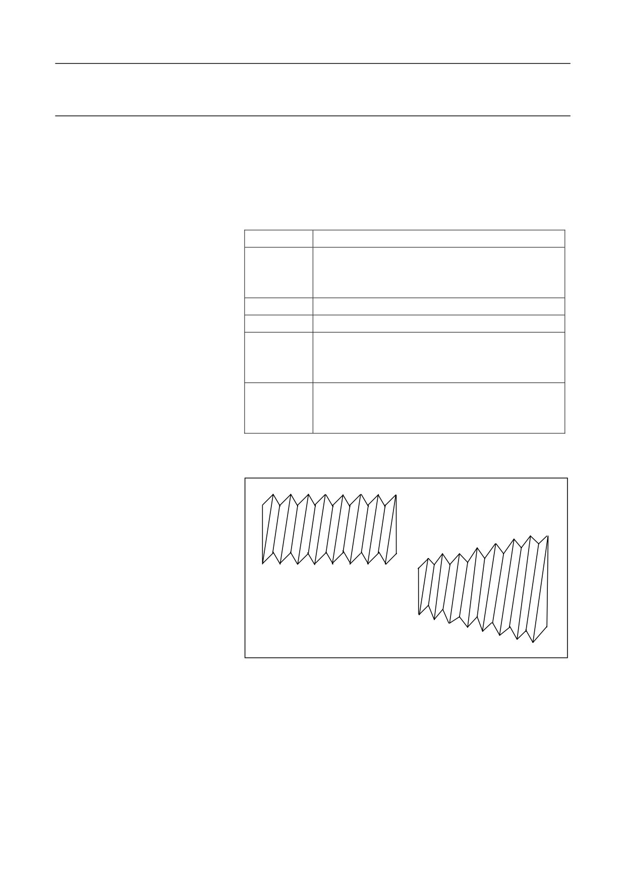
You may process multi-threads by specifying the thread start angle P.
For example, you may set P to 180 degrees to process double threads.
See the figure below:
54
5. Interpolation Functions
Retreat of tailstock
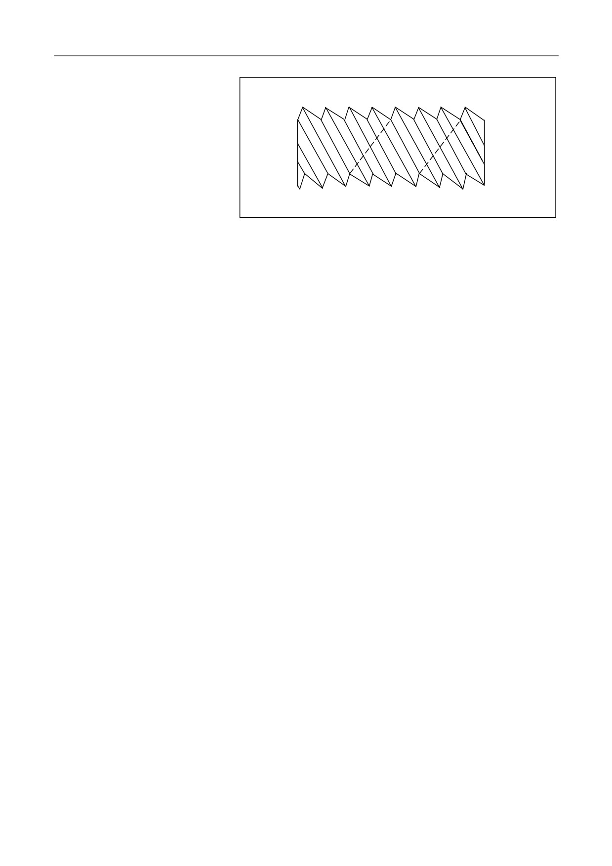
tailstock by specifying the R (retreat along the Z axis) and E (retreat
along the X axis) parameters, of which values are specified in the
incremental mode for both absolute and incremental programming. The
positive value indicates the retreat along the positive direction of the Z/X
axis, while the negative value indicates the retreat in the negative
direction of the Z/X axis. If no R or E value is specified, there will be no
retreat function.
According to the thread standard, R is generally specified as double pitch,
while E is specified as the height of the thread.
Note: If the retreat of tailstock is specified, the thread cutting direction
must be coordinated with the R/E direction to avoid damage to the
thread. For example, if the thread cutting is towards the negative
direction of the Z axis, then the value of R must be negative; otherwise,
there may be damage to the processed thread.
You may define the retreat of
Attention
1.
Do not change the feed rate or spindle override during thread
cutting.
2.
It is dangerous to stop the feed of the thread cutting tool without
stopping the spindle as it may suddenly increase the cutting depth;
therefore, the function of feed hold is invalid during thread cutting.
The feed hold is valid only during the non-thread machining.
3.
When thread cutting is conducted in the single block mode, the tool
will stop at the beginning of the first block where no threading
cutting is specified.
4.
During thread cutting, the work mode cannot be changed from the
auto mode into manual, incremental or reference mode.
55
5. Interpolation Functions
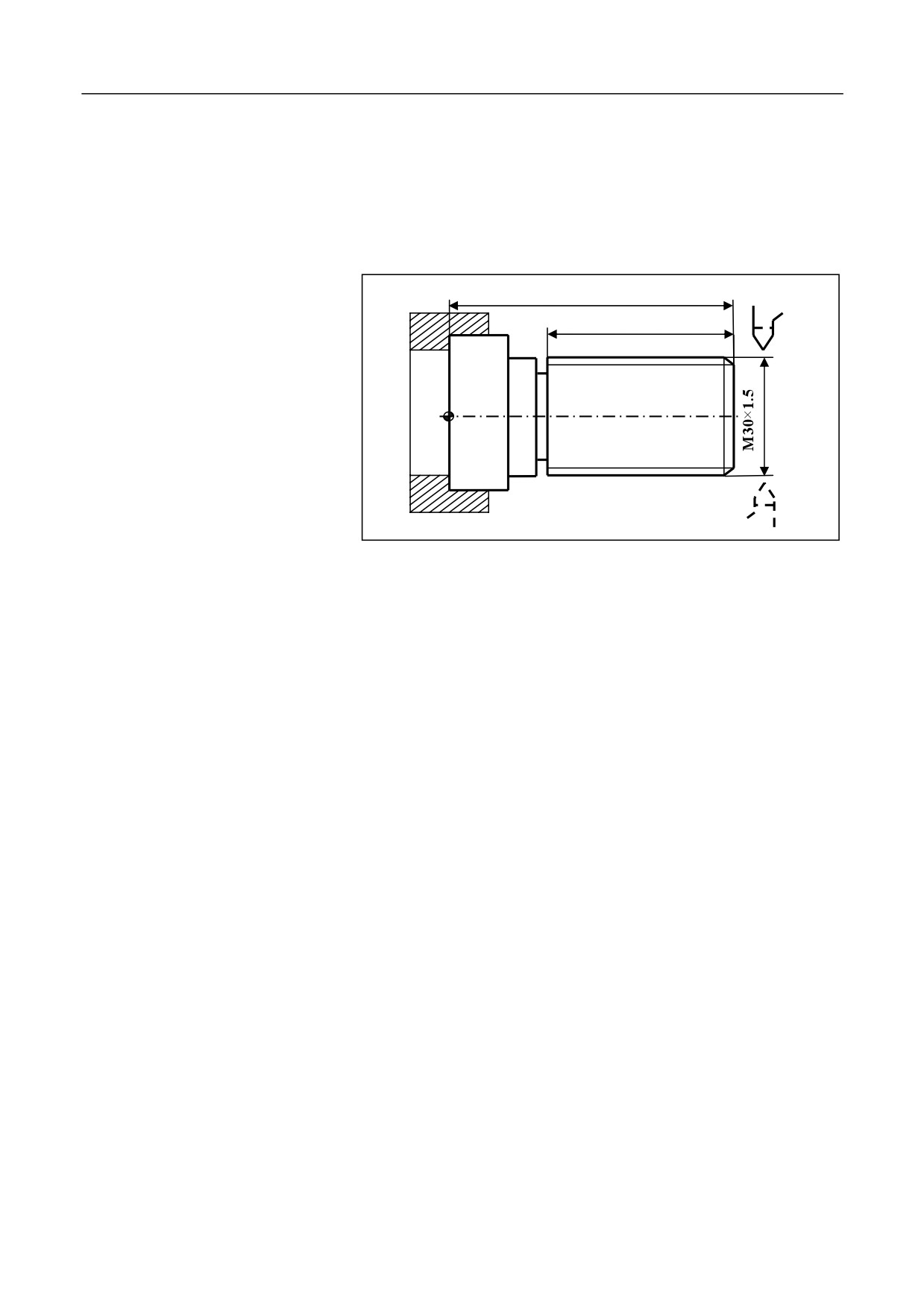
Example
The figure below shows the cylindrical thread programming. Thread lead:
1.5 mm; each cut depth (diameter value): 0.8 mm, 0.6 mm, 0.4 mm, 0.16
mm.
100
80
%3316
N1 T0101 (Set coordinate system, and select No. 1 tool)
N2 G00 X50 Z120 (Move to the start point position)
N3 M03 S300 (Rotate the spindle at 300 r/min)
N4 G00 X29.2 Z101.5 (Move to the start point, acceleration stage: 1.5
mm, cut depth: 0.8 mm)
N5 G32 Z19 F1.5 (Thread cutting to the end point, deceleration stage: 1
mm)
N6 G00 X40 (Quick retreat along the X axis)
N7 Z101.5 (Quick retreat to the start point along the Z axis)
N8 X28.6 (Fast forward to the start point along the X axis, cut depth: 0.6
mm)
N9 G32 Z19 F1.5 (Cut thread to the end point)
N10 G00 X40 (Quick retreat along the X axis)
N11 Z101.5 (Quick retreat to the start point along the Z axis)
N12 X28.2 (Fast forward to the start point along the X axis, cut depth:
0.4 mm)
N13 G32 Z19 F1.5 (Cut thread to the end point)
56
5. Interpolation Functions
N14 G00 X40 (Quick retreat along
the X axis)
N16 U-11.96 (Fast forward to the start point along the X axis, cut depth:
N15 Z101.5
(Quick retreat to the
0.16 mm)
start point along the Z axis)
N17 G32 W-82.5 F1.5 (Cut thread to the end point)
N18 G00 X40 (Quick retreat along the X axis)
N19 X50 Z120 (Back to the tool setting position)
N20 M05 (Stop the spindle)
N21 M30 (End the main program and reset)
57
5. Interpolation Functions
5.7 HSPLINE Spline Interpolation (HSPLINE)
HSPLINE is the abbreviation of Hermite SPLINE. The Hermite
interpolation function can also improve the machining results of small
lines, making the surface fairing. Different from the NURBS curves, the
Hermite curve passes through the control point. The CNC system may
conduct spline interpolation by specifying the control point and vectors
of the Hermite curve.
Format
HSPLINE P_ X_ Y_ Z_ I_ J_ K_ F_
Parameter
Description
X Y Z
Control point coordinates.
Note: The coordinate position must be the same as
the end point position of the previous line.
I J K
Vector of the control point
F
Hermite curve order
Cancel Interpolation
HSPLINE indicates modal of Group 01. You may cancel the HSPLINE
interpolation modal by specifying G01 or G00.
Curve order
P is used to specify the order of the HSPLINE curve: P must be set to 3.
Compensation
Tool radius compensation cannot be used for HSPLINE interpolation.
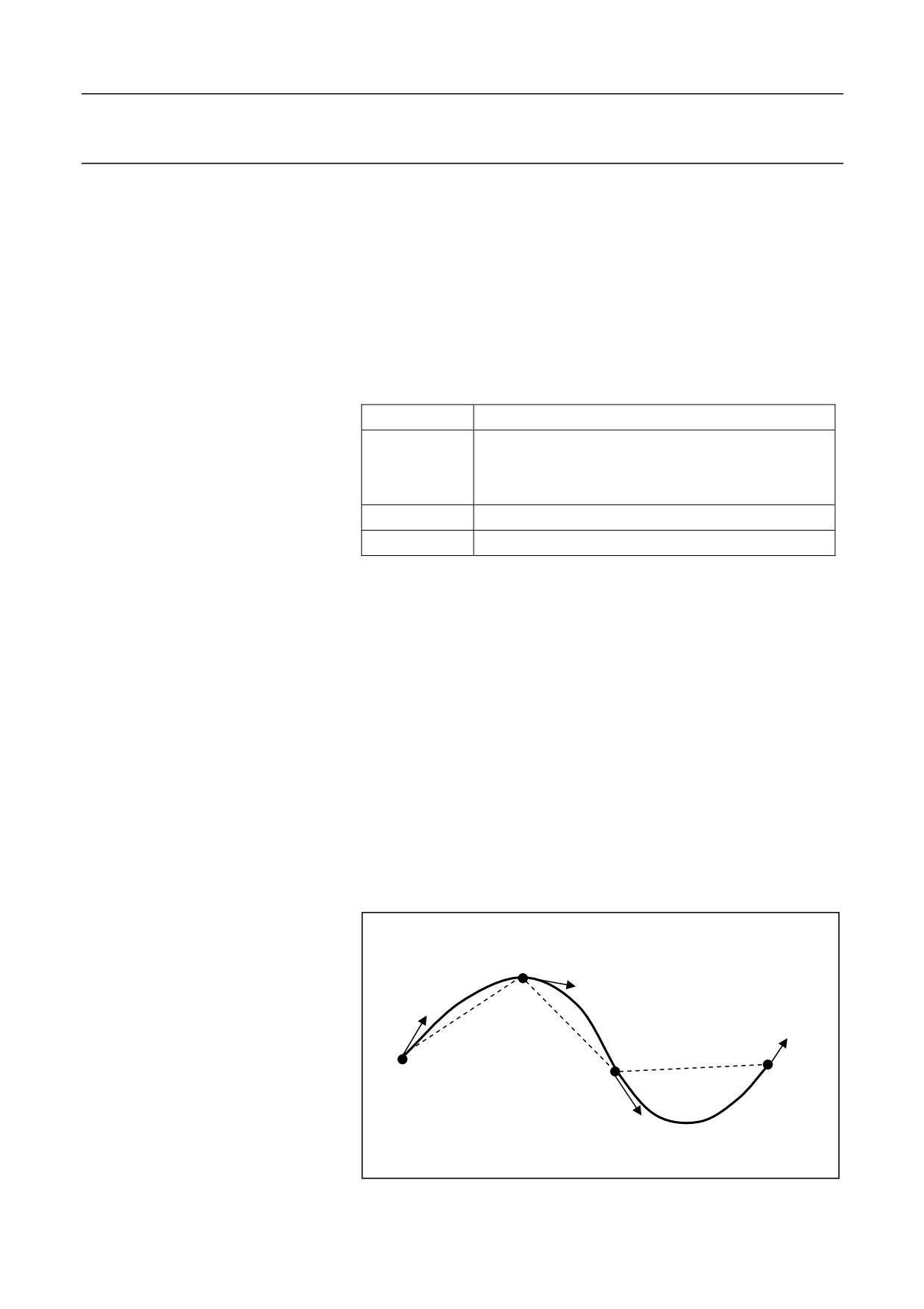
Example
Use cubic Hermite spline interpolation for the curve as below:
Q2
V2
V1
V4
Q3
Q1
Q4
V3
58