HNC-818. User Manual - page 5
10. Tool Compensation Functions
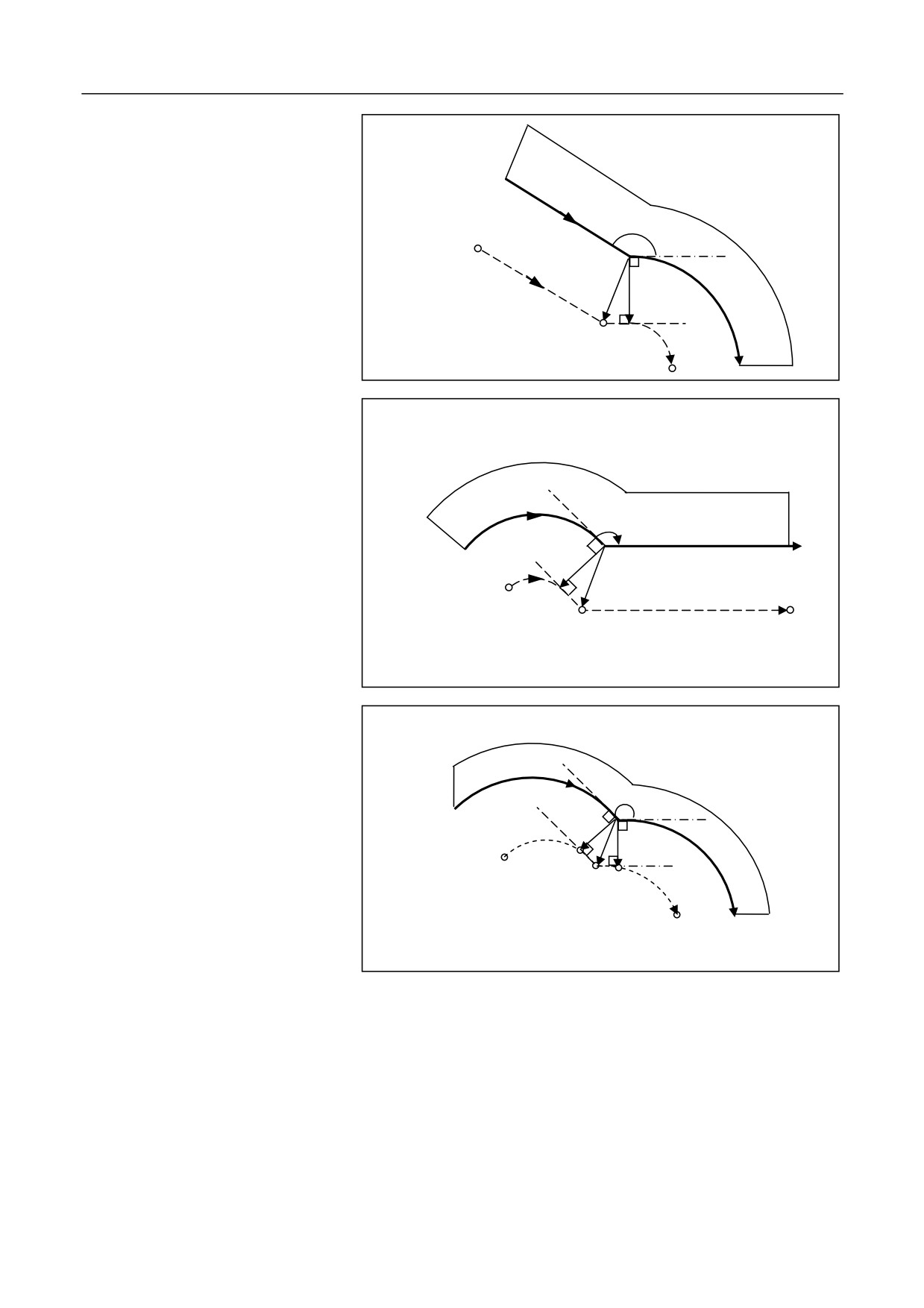
Linear ĺ Circular
Programming path
Į
Workpiece
r
Tool center path
L
S L
C
Intersection point
Circular ĺ Linear
Į
Workpiece
r
Programming path
C
S
L
Intersection point
L
Tool center path
Circular ĺ Circular
Į
Programming path
r
r
Workpiec
C
Tool center path
SL
L
C
Intersection point
121
10. Tool Compensation Functions
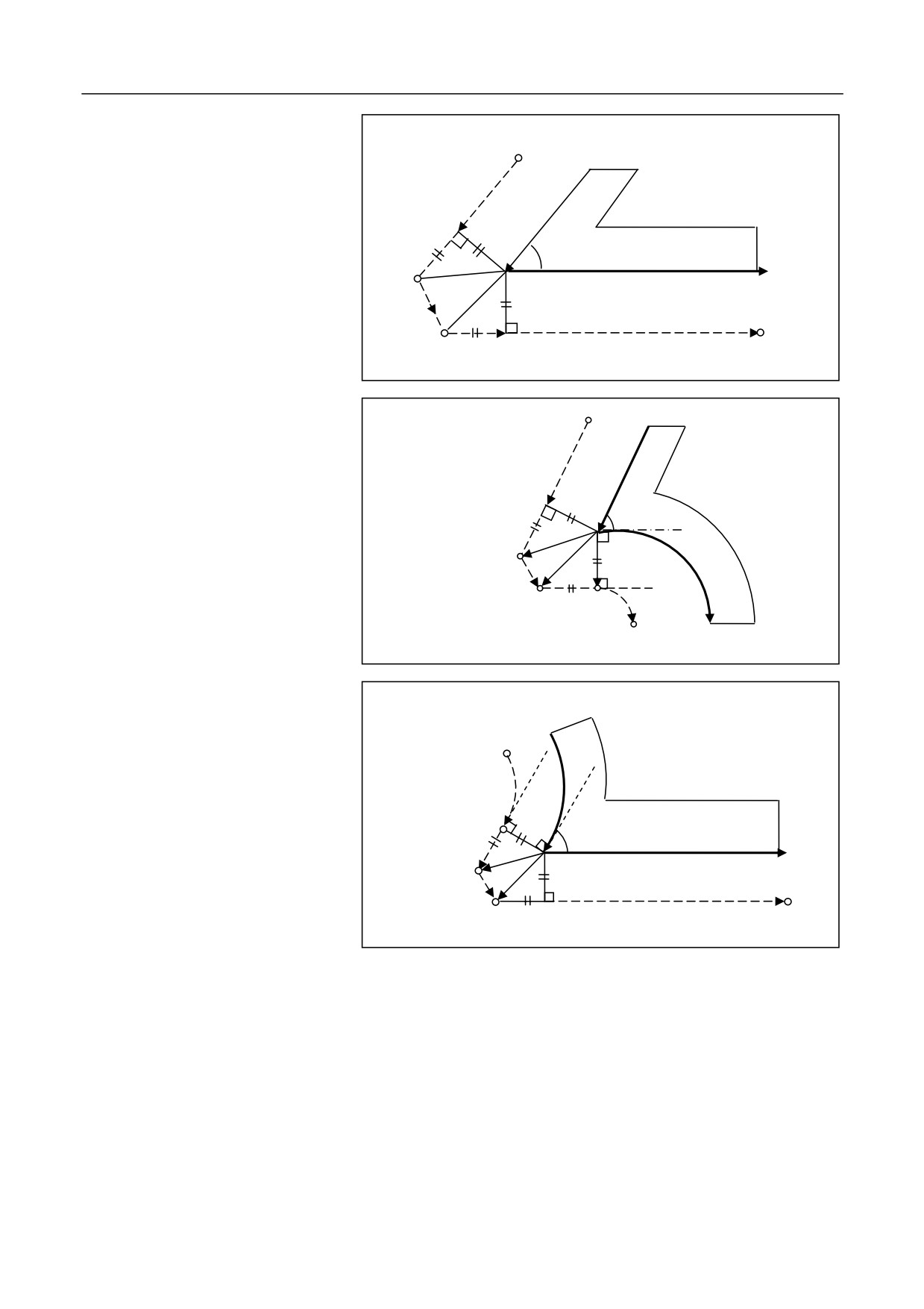
Tool movement around the outer
Linear ĺ Linear
corner
(Į<90 degrees)
L
r
L
Į
Workpiece
S
Programming path
r
L
L
L
Tool center path
Linear ĺ Circular
L
r
Į
L
Workpiec
S
r
L
L
C
Tool center path
Programming path
Circular ĺ Linear
C
S
r
Workpiec
L
Į
r
Programming path
L
L
Tool center path
122
10. Tool Compensation Functions
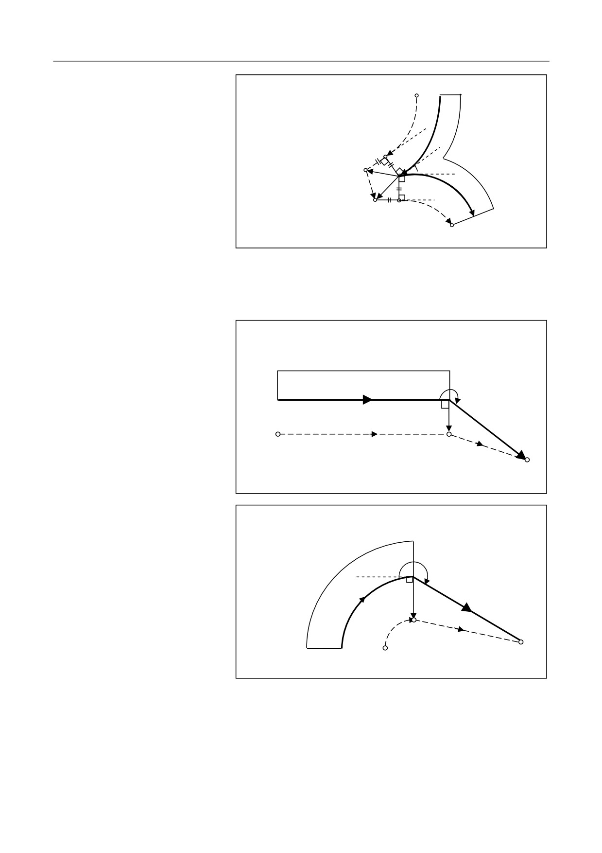
Circular ĺ Circular
Program
C
S
L
r
Į
L
r
Workpiece
L C
Tool center path
10.4.3 Tool Movement during Offset Cancelation
In the program block including
Linear ĺ Linear
offset cancelation, tool movement
around the inner corner
(Į180 degrees)
Workpiece
Į
G40
Programming path
r
Tool center path
L
S
L
Linear ĺ Circular
Į
Workpiece
G40
r
G42
S
C
L
Programming path
Tool center path
123
10. Tool Compensation Functions
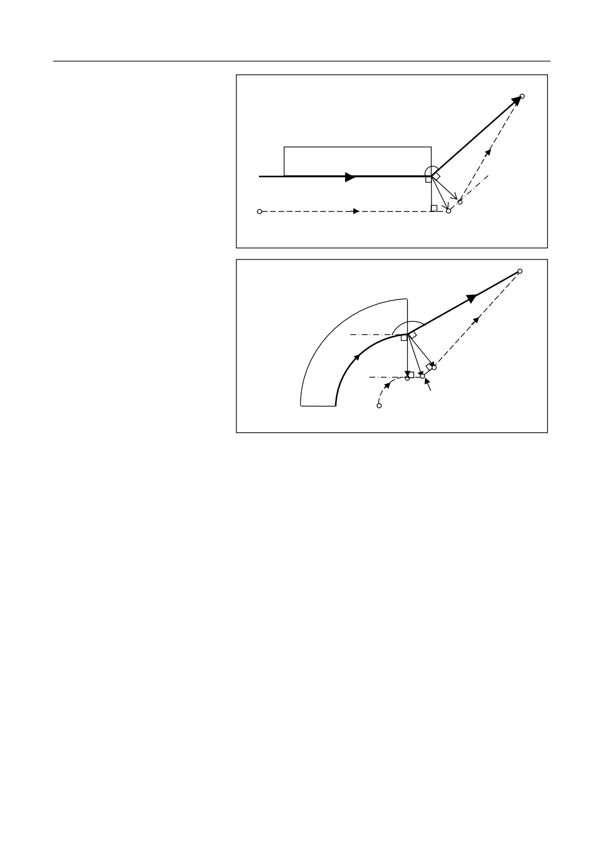
In the program block including
Linear ĺ Linear
offset cancelation, tool movement
around the outer obtuse angle
G40
(90 degrees Į<180 degrees)
L
Workpiec
Į
G42
r
Programming path
L
S
Tool center path
Intersection point
Circular ĺ Linear
G40
Į
L
Workpiece
r
L
S
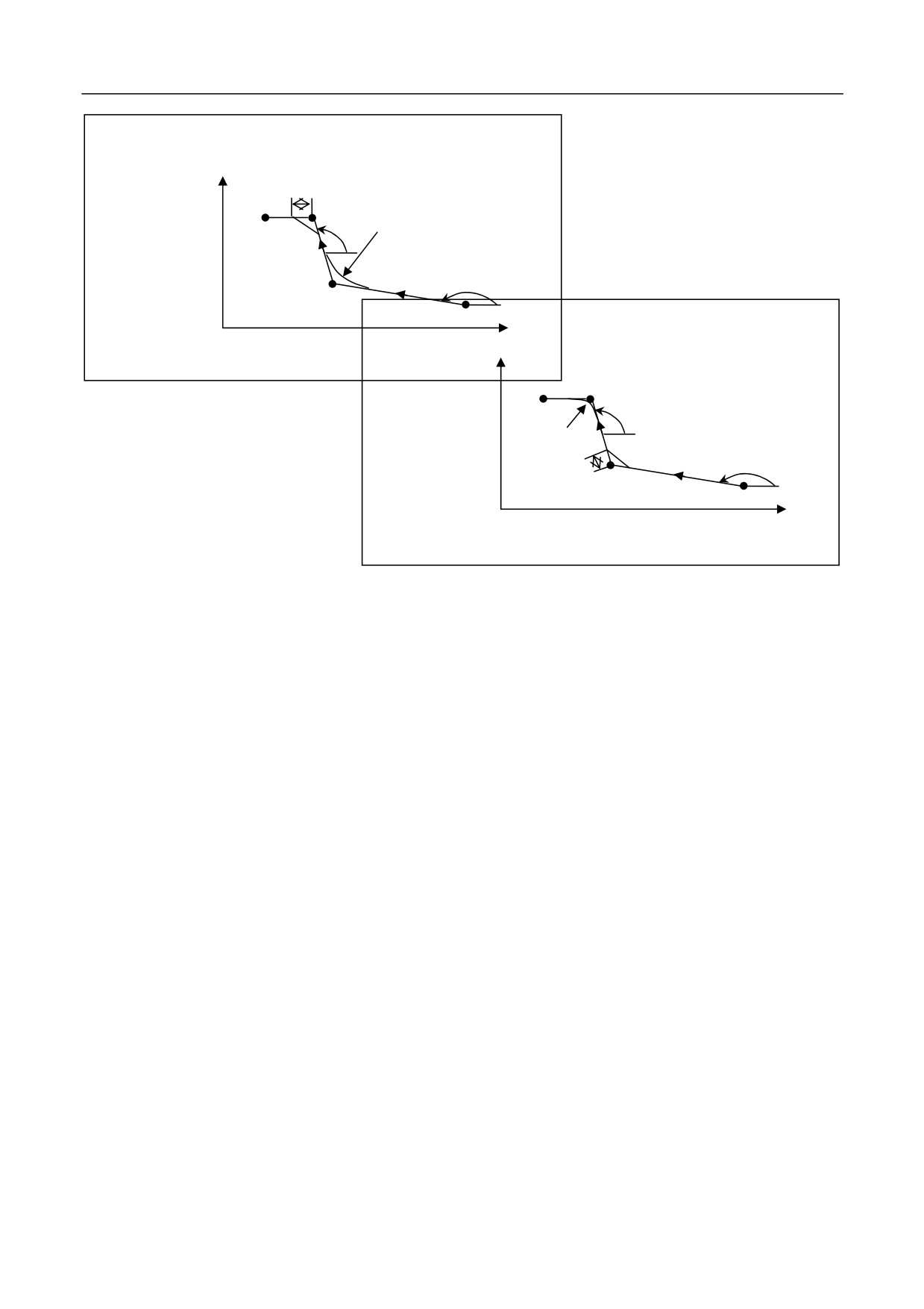
L
C Intersection point
Programming path
Tool center path
124
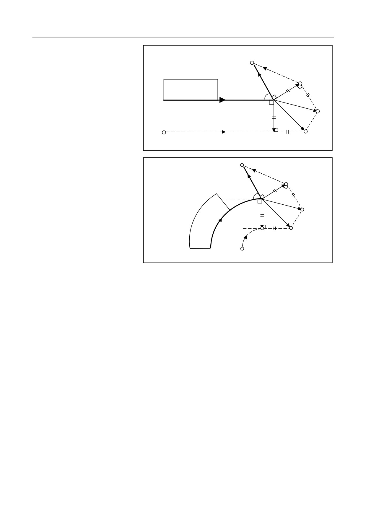
10. Tool Compensation Functions
In the program block including
Linear ĺ Linear
offset cancelation, tool movement
around the outer acute angle
L
G4
(Į<90 degrees)
Workpiece
Į
r
L
Programming path
r
Tool center path
L
L
L
S
Linear ĺ Circular
L
Į
r
L
r
L
Workpiece
S
C
L
Tool center path
Programming path
125
10. Tool Compensation Functions
10.5 Tool Length Compensation (M) (G43, G44, G49)
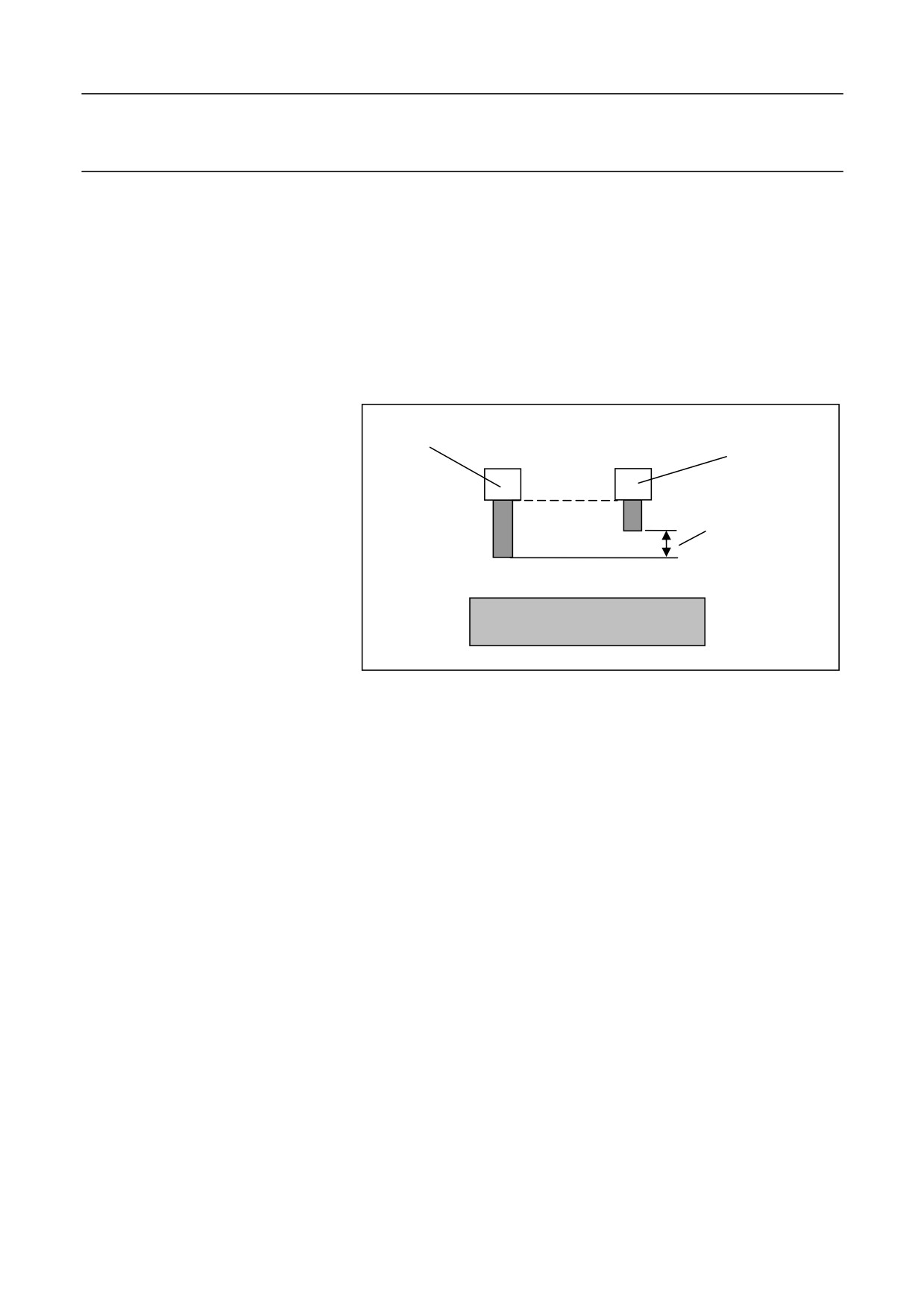
between the tool length specified in programming and the actual tool
length. You may save this difference in the CNC's tool offset register,
and then use the tool length compensation codes to conduct the
compensation for the difference, in order to simplify the operation and
programming. This way, even tools with different length are used for
machining, you may conduct normal machining without modifying the
program if you know the difference between the programmed tool length
and the actual length.
Programmed tool length
Actual tool length
Tool length compensation
Generally, there may be a difference
Attention
The length compensation does not support interruption codes such as
G31.
Abstract
There are three kinds of tool length compensation based on the type of
the axis allowed tool length compensation.
1.
Tool length compensation A
Tool length compensation along Z axis direction
2.
Tool length compensation B
Tool length compensation vertical to the selected plane
3.
Tool length compensation C
Tool length compensation along specified axis direction
126

10. Tool Compensation Functions
Format
Type
Format
Tool length compensation A
G43/G44 Z_H_
Tool length compensation B
G17 G43/G44 Z_H_
G18 G43/G44 Y_H_
G19 G43/G44 X_H_
Tool length compensation C
G43/G44 X_H_
G43/G44 Y_H_
G43/G44 Z_H_
……
Cancel tool length compensation
G49 IP_
Description
Tool length compensation is defined by G43 and G44.
G43: Tool length compensation in the positive direction (plus the tool
length compensation value to the theoretical position in the tool axis
direction)
G44: Tool length compensation in the negative direction (minus the tool
length compensation value to the theoretical position in the tool axis
direction)
G17: Select XY plane
G18: Select ZX plane
G19: Select YZ plane
H: The number of tool length compensation amount in the tool
compensation table
Attention
1.
The direction of tool length compensation is always vertical to the
plane defined by G17/G18/G19.
2.
When the offset number is changed, the new offset value will not be
added to the old offset value. Example:
H1: Tool length compensation amount
20.0; H2: Tool length
compensation amount 30.0
G90 G43 Z100 H01; Z reaches 120
G90 G43 Z100 H02; Z reaches 130
3.
G43, G44, G49 are modal codes which can be canceled by each
other.
4.
The axis movement is invalid if no tool length compensation after
G49.
127
10. Tool Compensation Functions
128
10. Tool Compensation Functions
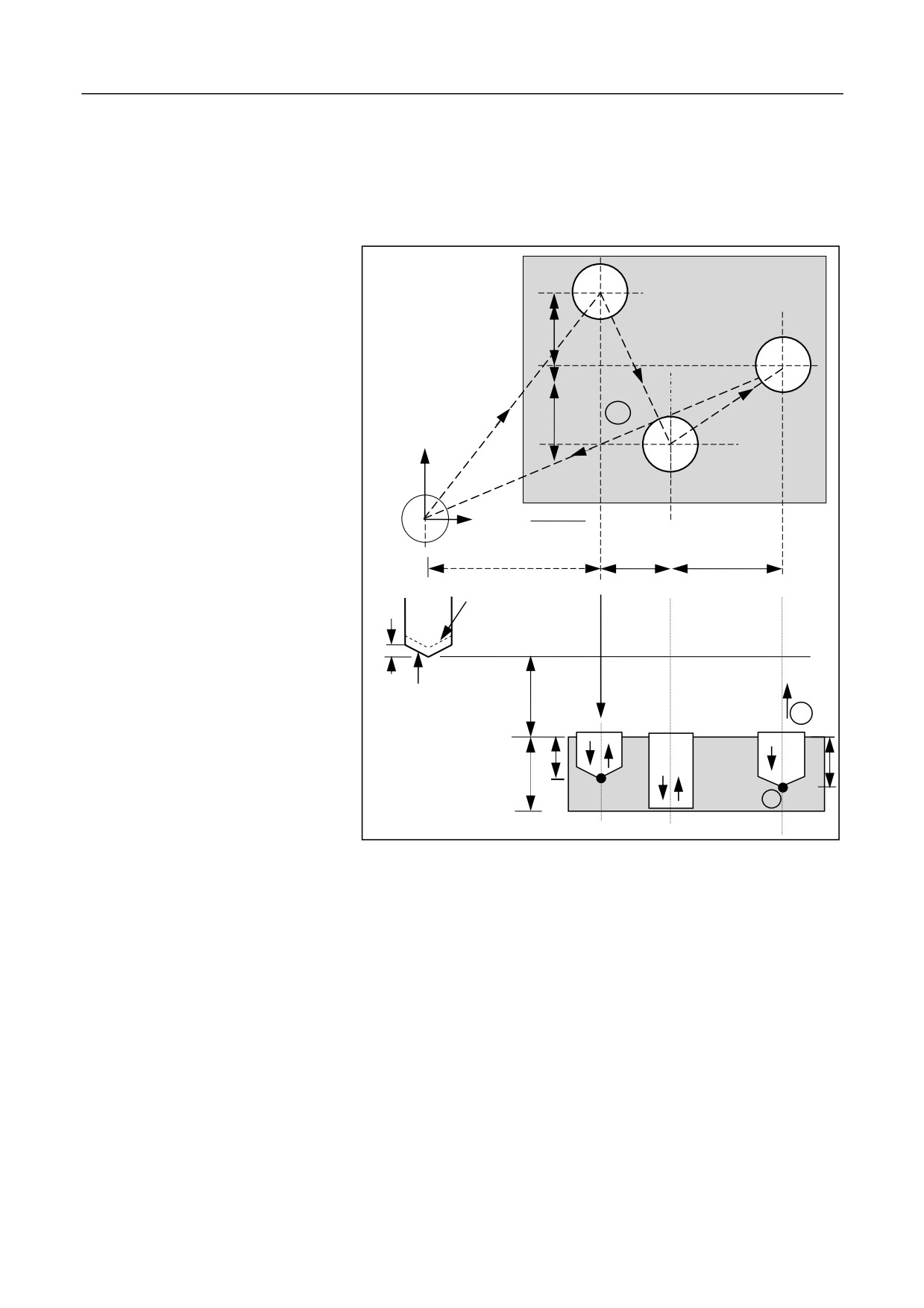
Example 1
Take into account the tool length compensation, and create a program for
the workpiece as shown in the figure below.
Requirements: establish a workpiece coordinate system and conduct
machining in the direction shown by the arrow in the figure below:
#1
#3
20
6
30
13
9
1
Y
#2
30
X
120
30
50
Offset value = 4mm
Actual position
○
35
Programming
12
position
3
5
7
8
10
18
22
30
4
11
H1 = -4.0 (tool length compensation value)
%3325
G92 X0 Y0 Z0
G91 G00 X120 Y80 M03 S600
1
G43 Z-32 H01
2
G01 Z-21 F300
3
G04 P2000
4
G00 Z21
5
X30 Y-50
6
129
10. Tool Compensation Functions
G01 Z-41
7
G00 Z41
8
X50 Y30
9
G01 Z-25
10
G04 P2000
11
G00 G49 Z57
12
X-200Y-60
13
M05
M30
130
11. Programming Simplification Functions
11 Programming Simplification Functions
This chapter includes the following sections:
11.1 Mirroring Function (M) (G24/G25)
11.2 Scaling Function (M) (G50/G51)
11.3 Rotation Function (M) (G68/G69)
11.4 Direct Programming Based on Blueprint Dimension (T)
131
11. Programming Simplification Functions
11.1 Mirroring Function (M) (G24, G25)
When the workpiece is symmetric around an axis, you may use the
mirroring functions and subprograms to create a program only for one
part of the workpiece, and other symmetrical parts can be produced. This
is called mirroring.
Format
G24 IP_; Create mirror
……
G25 IP0; Cancel mirror
Parameter
Description
IP
The position of the mirror axis.
Attention
1.
you may establish the symmetrical mirror of the ȕ axis by
specifying G24 Į_.
After establishing the mirror of the ȕ axis, you may cancel the
mirror of the ȕ axis by specifying G25 Į0. If you establish a
point-symmetrical mirror by specifying G24 X0Y0, the symmetrical
mirror of the Y axis can be canceled by specifying G25 X0, and
then only the X axis mirror is specified.
The character "Į" represents the first axis in the selected plane
while "ȕ" represents the second axis in the selected plane.
2.
G24 and G25 program blocks are specified in separate lines.
3.
G24 is a modal function. You may use G25 to cancel the mirroring
function after it is ended.
4.
When no axis is after G25, all mirroring functions are canceled.
132
11. Programming Simplification Functions
ȕ
Mirroring
path 1
Programming path
Description
60
Mirroring
Mirroring path 3
path 2
Į
50
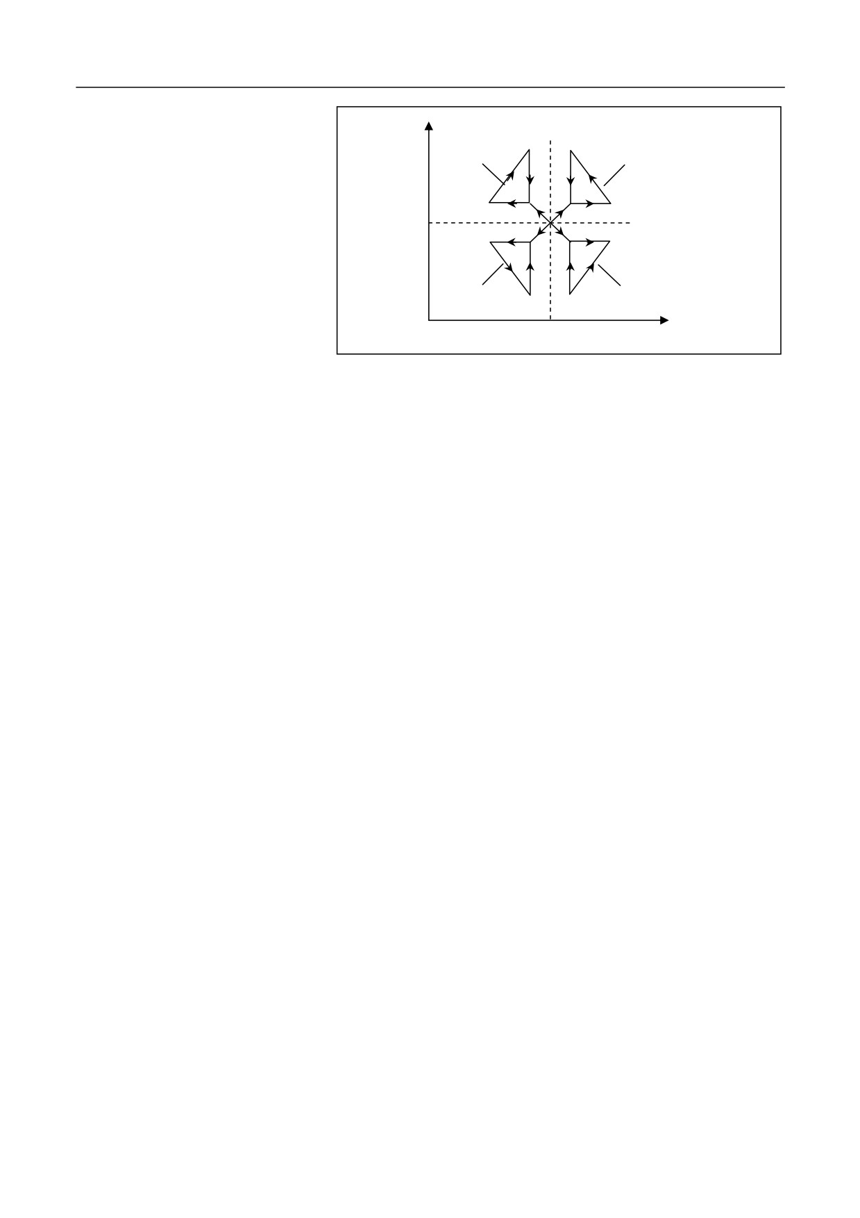
1.
The mirroring path 1 and the programming path is axisymmetric,
with the symmetry axis Į=50.
2.
The mirroring path 2 and the programming path is point-symmetric,
with the symmetry point (50, 60).
3.
The mirroring path 3 and the programming path is axisymmetric,
with the symmetry axis ȕ=60.
Axisymmetric mirror
(G17/G18/G19) G24 Į_/ȕ_;
…… ;
G25;
G17/G18/G19: Selects the mirror plane which should contain the
programming tool path.
G24 Į_/ȕ_: Specifies the symmetry axis of the mirror. You can only and
must specify either Į_ or ȕ_. The character "Į" represents the first axis in
the selected plane, and "ȕ" represents the second axis in the selected
plane. If an axis that is not in the selected plane is specified, an alarm
will be reported.
……: Programming command of tool path.
G25Į0/ȕ0: Cancels the mirroring function. Only the command G25 or
the command with G25 followed by the random value of "a" and "b" can
cancel the mirroring function.
Point-symmetric mirror
(G17/G18/G19) G24 Į_ ȕ_;
…… ;
G25;
133
11. Programming Simplification Functions
G17/G18/G19: Selects the mirror plane which should contain the
programming tool path.
G24 Į_ ȕ_: Specifies the symmetry point of the mirror. When Į_ or ȕ_ is
blank, the point is the actual tool position by default. If an axis that is not
in the selected plane is specified, an alarm will be reported.
……: Programming command of tool path.
G25Į0ȕ0: Cancels the mirroring function. Only the command G25 or the
command with G25 followed by the random value of "a" and "b" can
cancel the mirroring function.
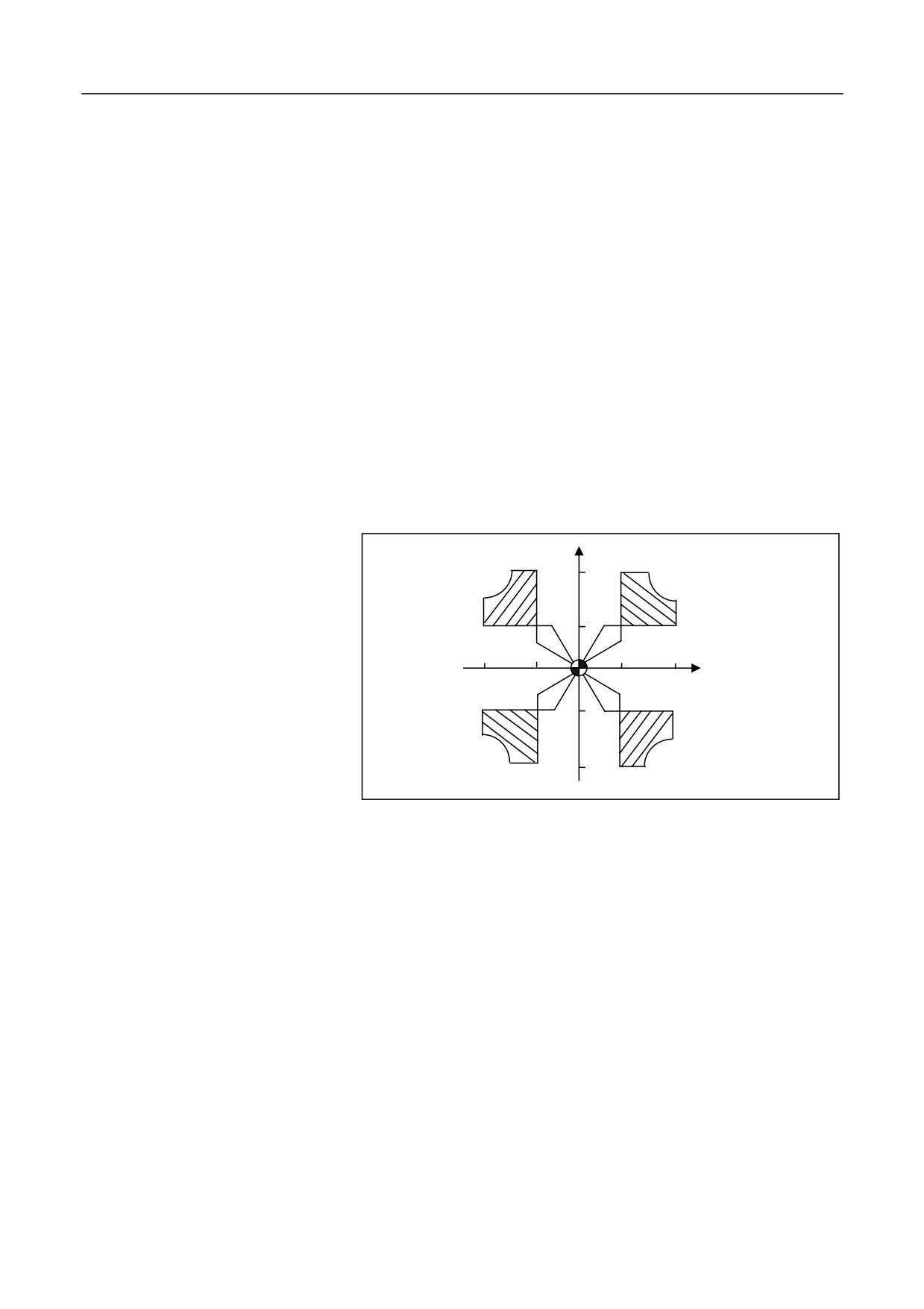
Example
Use the mirroring function to create a program for the machining of the
contour as shown in the figure below: The distance from the start point
of the tool to the workpiece surface is 100 mm, and the cutting depth is 5
mm.
Y
30
2
1
10
X
-30
-10
10
30
-10
3
4
-30
%3331 Main program
G92 X0 Y0 Z100
G91 G17 M03 S600
1
G24 X0; Y axis mirroring, with mirroring position X=0
2
G24 Y0; X&Y axis mirroring, with mirroring position (0, 0)
3
G25 X0; X axis mirroring remains valid, and cancel the Y axis mirroring
4
134
11. Programming Simplification Functions
G25 x0 Y0; Cancel mirroring
M30
1 ):
N100 G41 G00 X10 Y4 D01
N120 G43 Z10 H01
N130 G01 G90 Z-3 F300
N140 G91 Y26
N150 X10
N160 G03 X10 Y-10 I10 J0
N170 G01 Y-10
N180 X-25
N185 G00 Z10
N190 G90 G49 G00 Z100
N200 G40 X0 Y0
N210 M99
135
11. Programming Simplification Functions
11.2 Scaling Function (M) (G50, G51)
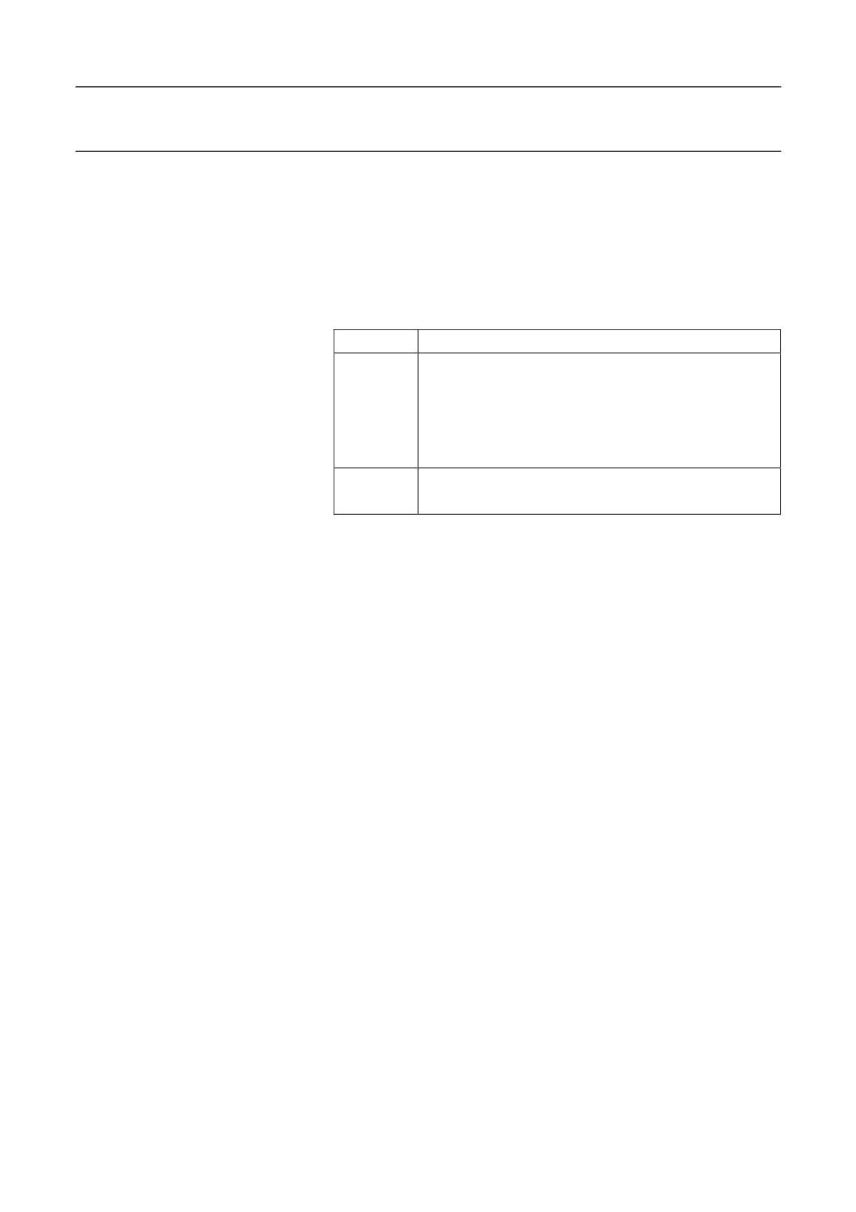
The scaling function can be used to zoom in or zoom out the
programming path by a given scaling factor.
Uniform scaling
G51 IP_ P_; Start scaling
……
G50; Cancel scaling
Parameter
Description
IP
Specify the center point coordinates for the scaling. If
the center point is not specified, the current point will be
specified by default.
The command always specifies the absolute position of
the scaling center in the workpiece coordinate system.
P
Specifies the scaling factor for each axis.
All axes are scaled according to the scaling factor.
Tool Compensation
In the case of tool compensation, scaling is conducted before the tool
radius compensation or tool length compensation. The scaling will not
change the tool radius compensation value or tool length compensation
value.
Attention
1. Specify G51 block in a separate line.
2. Use G50 to cancel the scaling after the scaling is completed.
3. In the G51 block, either in the incremental (G91) or absolute mode
(G90), the center coordinates of the scaling IP_ refers to the absolute
position in the workpiece coordinate system.
136
11. Programming Simplification Functions
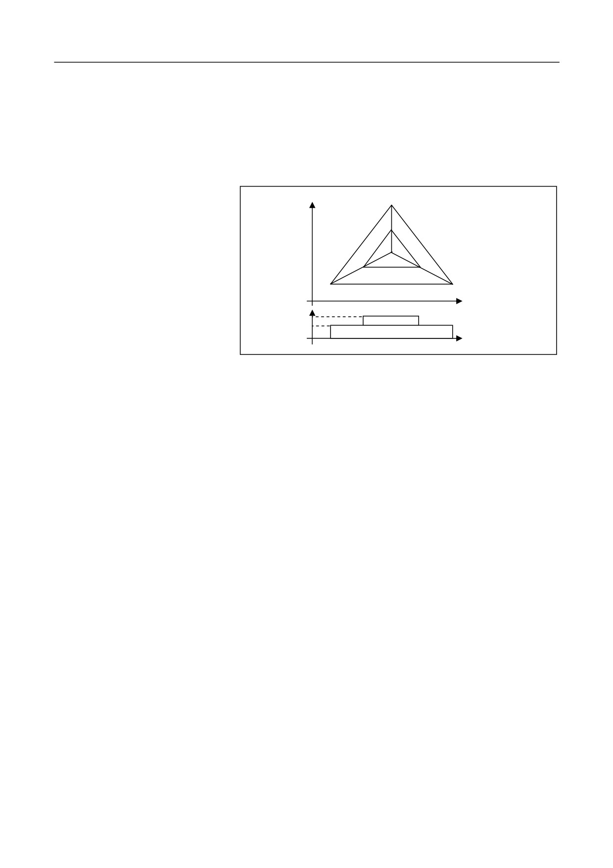
Example
Use the scaling function to create a program for the machining of the
contour as shown in the figure below: The apexes of the triangle ABC
are A (10, 30), B (90, 30), C (50, 110); the triangle A'B'C 'is the shape
after scaling, with the scaling center D (50, 50)and the scaling factor 0.5;
the distance from the start
point of the tool to the surface
of
the
workpiece is 50 mm.
C (50, 110)
Y
C’
D
A’
B
B (90, 30)
O A (10, 30)
X
Z
10
6
X
%3332; Main program
G92 X0 Y0 Z60
G17 M03 S600 F300
G43 G00 Z14 H01
X110 Y0
#51=0
M98 P100; Machining for the triangle ABC
#51=6
G51 X50 Y50 P0.5; Scaling center (50, 50), scaling factor 0.5
M98 P100; Machining for the triangle A'B'C'
G50; Cancel the scaling
G49 Z60
G00 X0 Y0
M05 M30
137
11. Programming Simplification Functions
%100; Sub program (program for the triangle ABC)
N100 G41 G00 Y30 D01
N120 Z[#51]
N150 G01 X10
N160 X50 Y110
N170 G91 X40 Y-80
N180 G90 Z[#51]
N200 G40 G00 X110 Y0
N210 M99
138
11. Programming Simplification Functions
11.3 Rotation Function (M) (G68, G69)
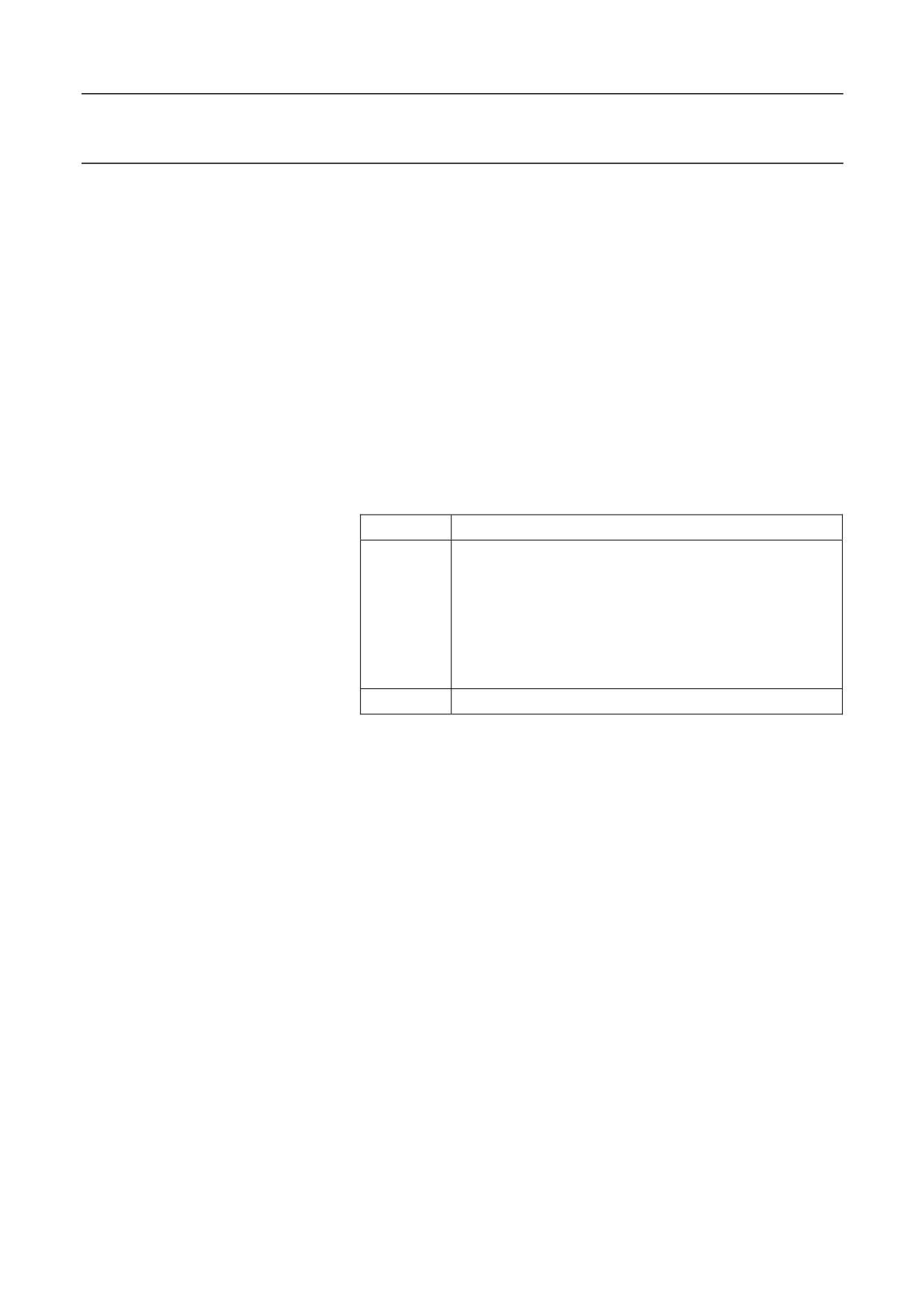
The rotation function can be used to rotate the programming path around
the rotation center with the specified angle. If the workpiece consists of
multiple parts with the same shape, you may create sub programs and
then use the rotation command to call the subprograms.
It can simplify the programming and save storage space.
Format
G17/G18/G19; Select a rotation plane
G68 IP_ P_; Establish rotation
……
G69; Cancel rotation
Parameter
Description
IP
Specifies the rotation center coordinate. If nothing is
specified as the rotation center, the current point of the
tool will be specified by default.
Either in the incremental or absolute mode, the specified
value refers to the absolute position in the workpiece
coordinate system.
P
Rotation angle (unit: degree)
Rotation angle
The rotation angle P ranges from -360 to 360 degrees, positive in the
counterclockwise direction and negative in the clockwise direction.
Either specified by G90 or G91, P is always the absolute value of the
angle which is based on the positive direction of the first axis in the
specified plane.
Tool compensation
Conduct tool radius compensation, tool length compensation, tool offset,
and other compensation after the coordinate system rotation. If rotation
and scaling are both required, rotation should be programmed prior to the
scaling function; otherwise a message prompting you "SWITCHING
NESTING ORDER ERROR." will be displayed.
Attention
1.
The G code (G28, G29, G30, etc.) related to reference or the
command used for changing the coordinate system (G52, G54-G59,
G54.X, G92, etc.) cannot be specified in the rotation mode. To
specify such commands, please firstly cancel the coordinate rotation
command.
139
11. Programming Simplification Functions
2.
If you Specify G68 and G69 in the tool radius compensation mode,
the rotation plane must be consistent with the tool radius
compensation plane.
3.
Use G69 to cancel the rotation function after it is completed.
4.
Specify the G68 program block in a separate line.
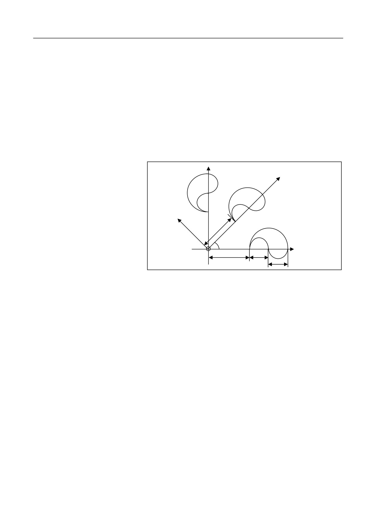
Example
Use the rotation function to create a program for the machining of the
contour as shown in the figure below: the distance from the tool start
point to the workpiece surface is 50 mm, and the cutting depth is 5 mm.
Y
X’
错误
错误
Y’
20
20
45°
错误
X
20
10
10
%3333; Main program
N10 G92 X0 Y0 Z50
N15 G90 G17 M03 S600
N20 G43 Z-5 H02
1
N30 G68 X0 Y0 P45; Rotate 45 degrees
2
N60 G68 X0 Y0 P90; Rotate 90 degrees
3
N20 G49 Z50
N80 G69 M05 M30 ; Cancel rotation
1
G41 G01 X20 Y-5 D02 F300
N105 Y0
140
11. Programming Simplification Functions
N110 G02 X40 I10
N120 X30 I-5
N130 G03 X20 I-5
N140 G00 Y-6
N145 G40 X0 Y0
N150 M99
141
11. Programming Simplification Functions
11.4 Direct Programming based on Blueprint Dimensions (T)
Straight angles, chamfering values, corner arc transition values and other
dimensional values on machining blueprint can be directly entered for
programming. In addition, chamfer or transition arc can be inserted
between the straight lines of any dip angle. This program mode is called
direct programming based on blueprint dimensions.
This programming mode is used only for G01 command of turning
series G01.
Command format
The programming mode consists of eight command modes. The meaning
of each character is as below:
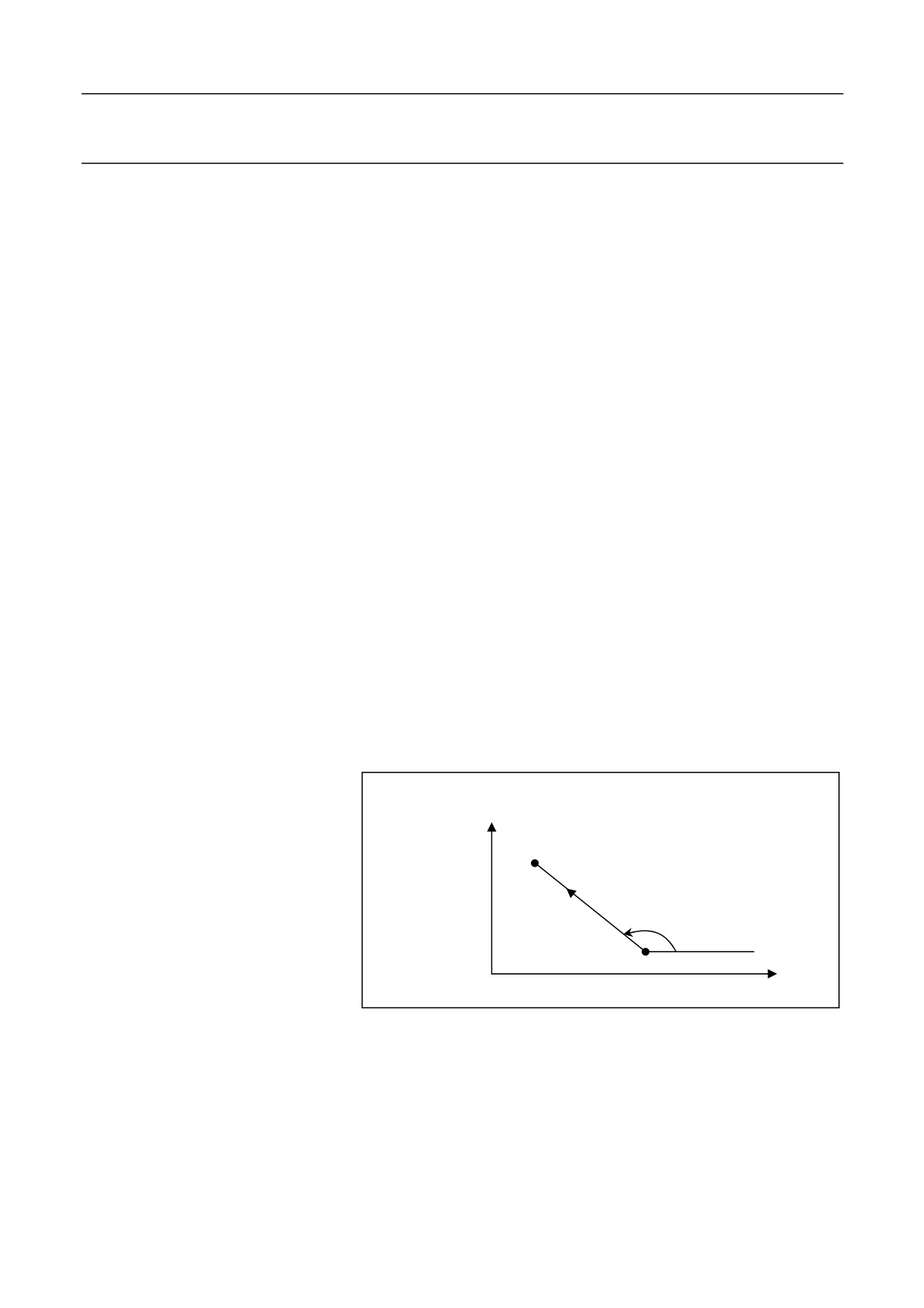
X_/Z_: Linear destination address word
A_: The angle between the direction of linear movement and the positive
direction of Z-axis, negative in the clockwise direction and positive in
the counterclockwise direction. Unit: degree.
C_: Chamfer side length.
R_: Rounding radius.
1.
Specify a straight line
X
(X2, Z2)
X1_Z1_
X2_(Z2_)A_;
A
(X1, Z1)
Z
Note: You can only specify the amount of displacement in one direction
for the target position. For example: Z50a45 or X100a45.
142
11. Programming Simplification Functions
2.
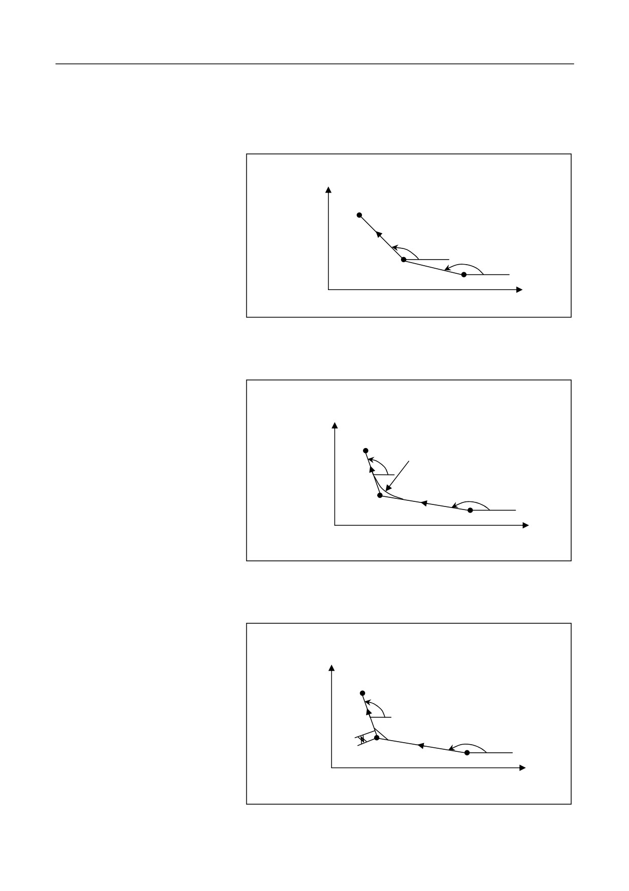
Specify straight lines continuously
X
(X3, Z3)
X1_Z1_
A1_;
A2
X3_Z3_A2_;
A1
(X2, Z2)
(X1, Z1)
Z
3.
Rounding
X
(X3, Z3)
X2_Z2_R1_;
A2 R1
X3_Z3_
or
A1
A1_R1_;
(X2, Z2)
(X1, Z1)
X3 Z3 A2 ;
Z
4.
Chamfer
X
X2_Z2_C1_;
(X3, Z3)
X3_Z3
A2
or
A1_C1_;
A1
C1
X3_Z3_A2_;
(X2, Z2)
(X1, Z1)
Z
143
11. Programming Simplification Functions
5.
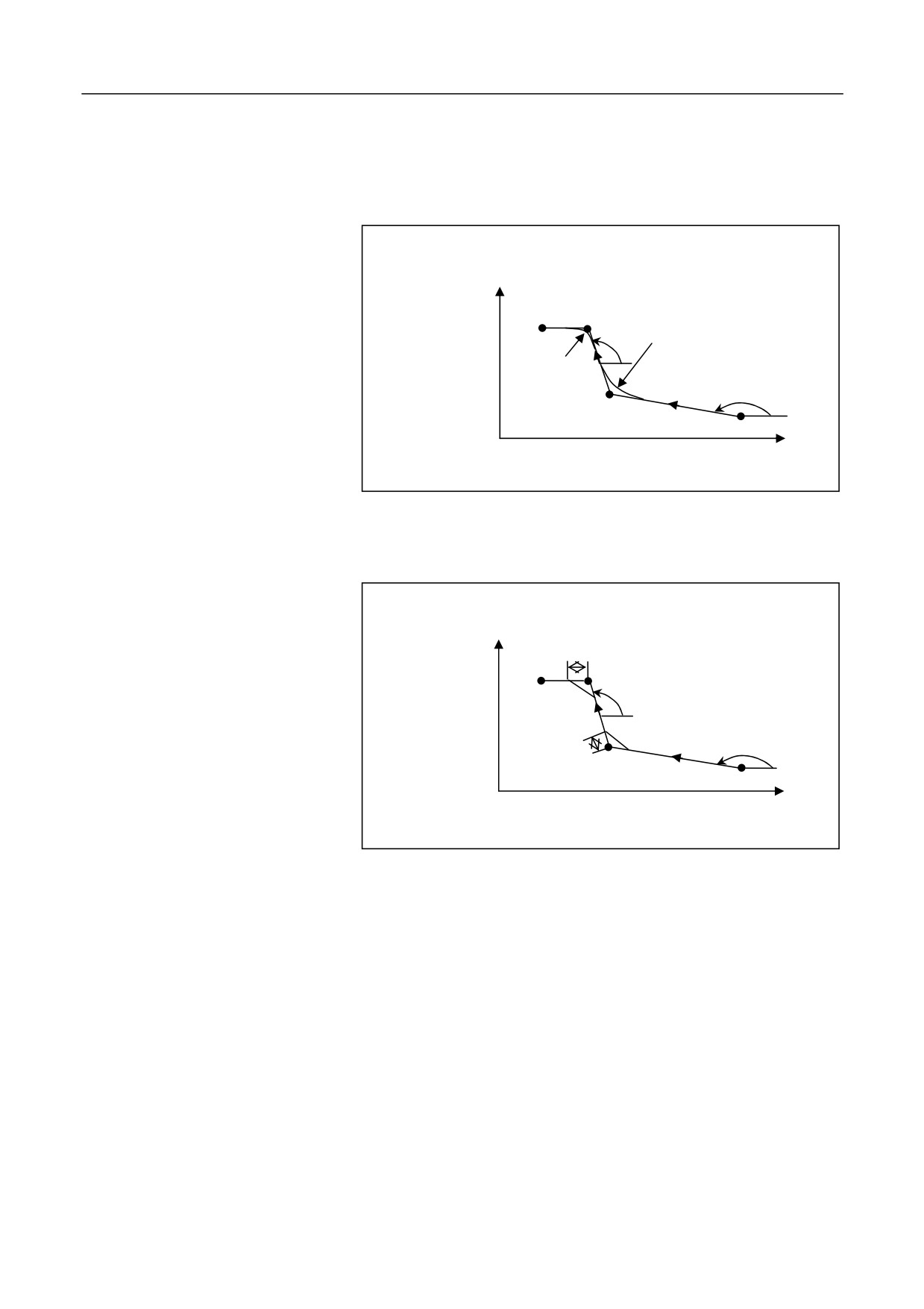
Continuous rounding
X
X2_Z2_R1_;
(X4, Z4)
(X3, Z3)
X3_Z3_R2_;
A2
R1
X4_Z4_
R2
or
A1_R1_;
A1
(X2, Z2)
X3_Z3_A2_R2;
X4_Z4_;
Z
6.
Continuous chamfer
X
X2_Z2_C1_;
C2
(X3, Z3)
X3_Z3_C2_;
X4_Z4_
A2
(X4, Z4)
or
A1_C1_;
A1
C1
(X2, Z2)
X3_Z3_A2_C2;
X4_Z4_;
Z
7.
Rounding and then chamfer
144
11. Programming Simplification Functions
X
X2_Z2_R1_;
C2
X3_Z3_C2_;
(X3, Z3)
X4_Z4_
A2
R1
(X4, Z4)
or
A1_R1_;
8.
Chamfer and then rounding
A1
X3_Z3_A2_C2;
(X2, Z2)
X4_Z4_;
Z
X
X2_Z2_C1_;
X3_Z3_R2_;
(X4, Z4)
(X3, Z3)
X4_Z4_
A2
or
R2
A1_C1_;
A1
C1
X3_Z3_A2_R2;
(X2, Z2)
X4_Z4_;
Z
Attention
To avoid the conflicts between the address word in this function and the
axis name, make sure to set the channel parameter Parm040035
[ANGLE PROGRAMMING ENABLED] (channel 0) when using this
function.
145
12. Fixed Cycle
12 Fixed Cycle
During CNC machining, some machining cycle has been stylized. Some
typical machining operations such as drilling, boring, milling, turning,
etc., are pre-created via the macro program and are saved in the system.
Call the programs through G codes to simplify the programming. This
chapter includes the following sections:
12.1 Drilling Fixed Cycle for Milling Machines
12.2 Simple Cycle for Turning Machines
12.3 Drilling Fixed Cycle for Turning Machines
12.4 Combined Cycle for Turning Machines
12.5 Exceptions in Fixed Cycle
146
12. Fixed Cycle
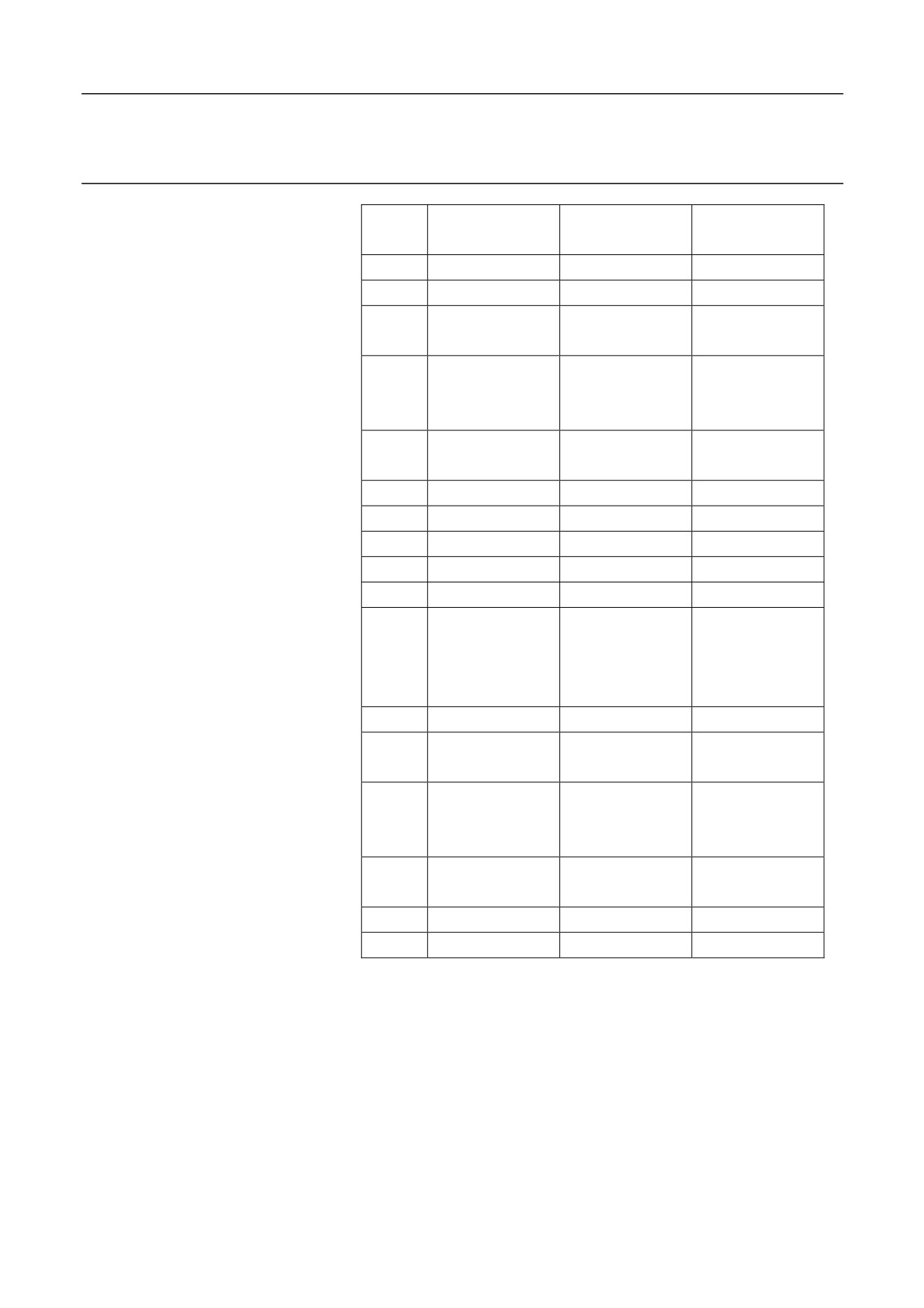
12.1 Drilling Fixed Cycle for Milling Machines (M)
Commands of drilling fixed cycle
G
Drilling (-Z
Action at the
Tool Exist (+Z
for milling machines
Code
Direction)
Hole Bottom
Direction)
G70
Cutting feed
Pause
Rapid tool exit
G71
Cutting feed
Pause
Rapid tool exit
G73
Intermittent
Pause
Rapid tool exit
cutting feed
G74
Cutting feed
Pause—Spinlde
Cutting back
clockwise
roation
G76
Cutting feed
Spindle
Rapid tool exit
orientation
G78
Cutting feed
Pause
Rapid tool exit
G79
Cutting feed
Pause
Rapid tool exit
G81
Cutting feed
—
Rapid tool exit
G82
Cutting feed
Pause
Rapid tool exit
G83
Cutting feed
Pause
Rapid tool exit
G84
Cutting feed
Pause—Spindle
Cutting back
counter
clockwise
roation
G85
Cutting feed
—
Cutting back
G86
Cutting feed
Pause—Spindle
Rapid tool exit
stop
G87
Cutting feed
Spinlde
Rapid tool exit
clockwise
roation
G88
Cutting feed
Pause—Spindle
Manually
stop
G89
Cutting feed
Pause
Cutting back
G80
—
—
—
Drilling actions
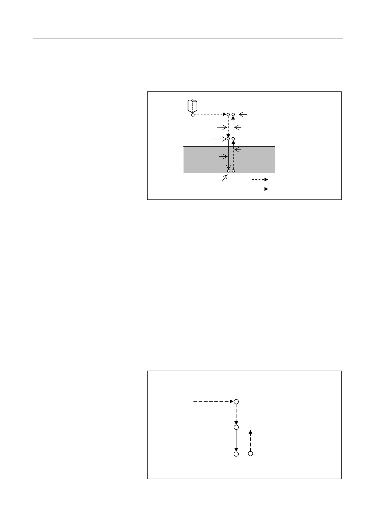
Generally there are six actions for the drilling cycle in order:
Action 1: X&Y axis positioning
Action 2: Rapidly move to the R plane
Action 3: Execute drilling
147
12. Fixed Cycle
Action 4: Operations at the hole bottom
Action 5: Exit the tool to the R plane
Action 6: Rapidly exit the tool to the initial Z plane
Operation 1
Intital level
Operation 2
Operation 6
R Level
Operation 5
Operation 3
Rapid traverse
Operation 4
Feed
Locate plane
G17 plane (X, Y axis)
Drilling axis
Z axis
Drilling data
G73, G74, G76 and the codes from G81 to G89 are modal G codes,
which are valid before they are canceled. The parameters defined in
these drilling cycle commands are modal data, which indicates that the
parameters are valid before they are canceled.
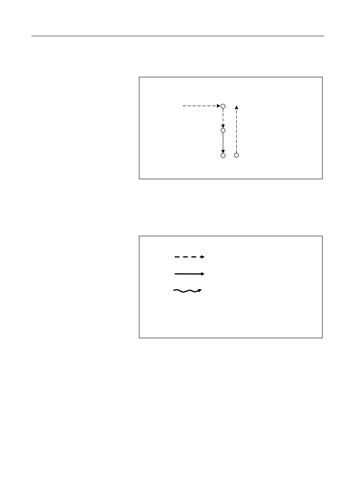
Return to the reference plane G99
The G99 command can be used to return to the reference point plane
specified by the R parameter after the fixed cycle is ended.
Initial plane
R level
148
12. Fixed Cycle
Return to the start plane G98
The G98 command can be used to return to the start plane where the
fixed cycle is commanded after the fixed cycle is ended. G98 is the
initial modal G code of Group 15.
Initial plane
R level
Cancle the fixed cycle
G80 or the G codes of Group 01 can be used to cancle the fixed cycel.
Symbol description
Positioning (rapid traverse G00)
Cutting feed (linear interpolation G01)
Manual feed
P
Dwell
Attention
1.
When the fixed cycle program lines without X, Y, Z axis movement
command are executed, the tool will not move, but the cycle
parameter modal value of the current lines will be saved.
2.
Specifying the G code of Group 1 or G80 will cancel the current
fixed cycle G code modal, and also clear the cycle parameter modal
value.
3.
If you need to execute the fixed cycle repeatedly by specifying L,
an alarm will be reported when L is set to 0.
149
12. Fixed Cycle
4.
When the G53 command is specified in a fixed cycle block, its
positioning data (X, Y) is still the original workpiece coordinate
system data, but not the coordinate system data specified by G53.
Example:
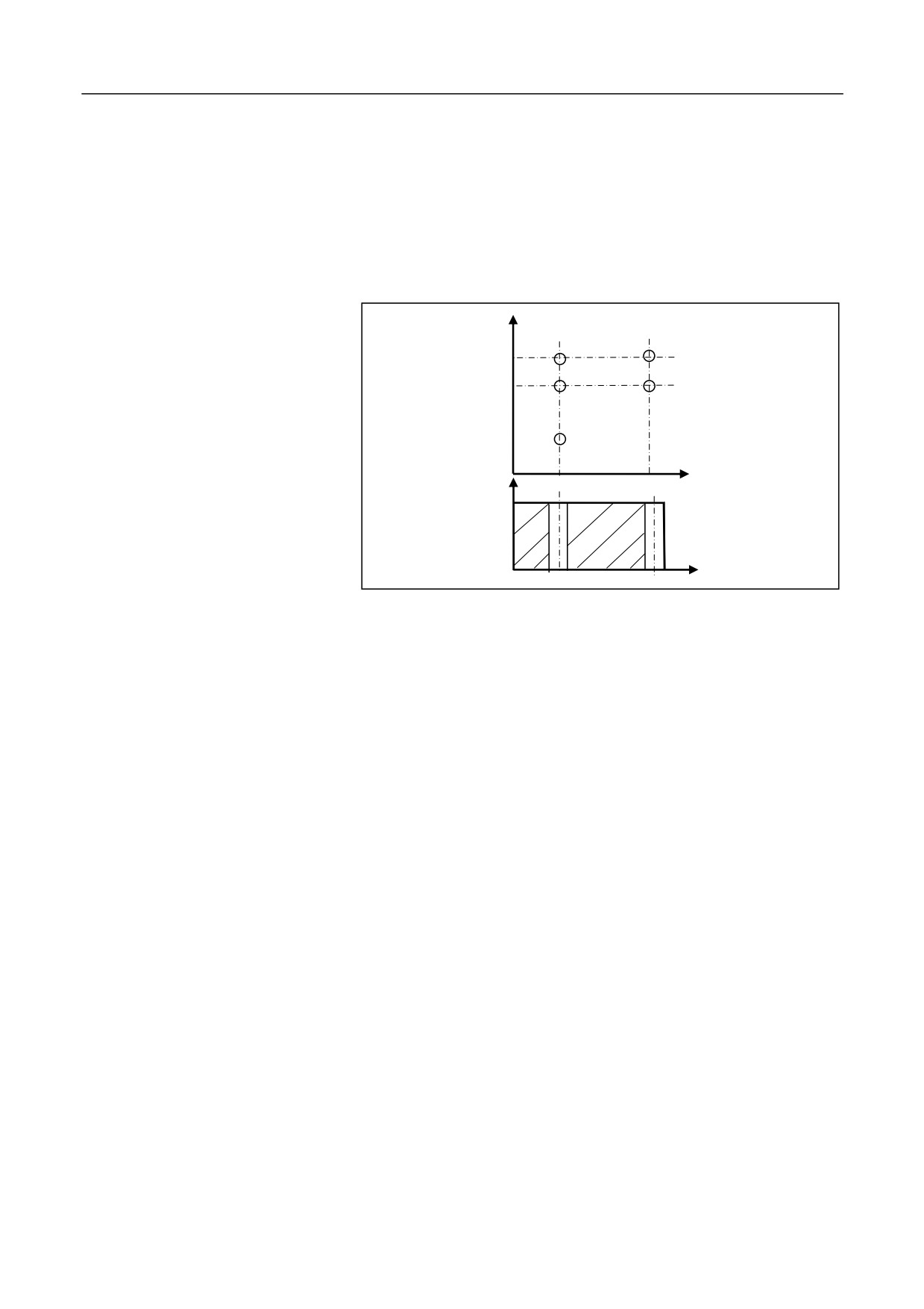
Use ĭ10 drilling bit to drill the holes shown in the figure below:
Y—
—750
—550
—250
X+
Z—
1000
300
—150
X+
Program example
%5647
G54
G90 X0 Y0 Z80
M3 S1000;
G90 G99 G81 X300 Y-250 Z-150 R-120 F120; Position, drill hole 1,
return to the point of R
Y-550; Position, drill hole 2, return to the point of R
Y-750; Position, drill hole 3, return to the point of R
X1000; Position, drill hole 4, return to the point of R
Y-550; Position, drill hole 5, return to the point of R
G98 Y-750; Position, drill hole 6, return the initial plane
G80 G28 G91 X0 Y0 Z0; Cancel the fixed cycle and return to the
reference point
M5;
M30
150
12. Fixed Cycle
12.1.1 Circumference Drilling Cycle (G70)
Description
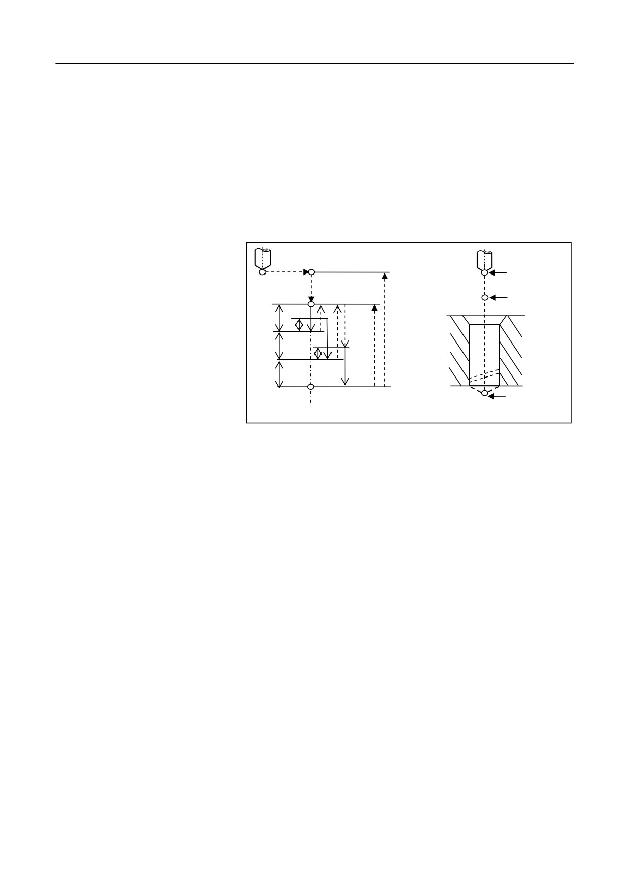
In the circumference with the radius I and the center being the coordinate
(X, Y). Divide the circle into N equal parts based on the angle J and the
X axis. Conduct drilling for N holes. Execute fixed cycle of G81 and
G83 based on the value of Q, K for each hole. The movement between
holes is performed through G00. G70 is a modal code, and the command
word following it is non-modal.
Initial point B
Initial point B
Reference
G98
point R
Reference
point R
Q
k
G99
Q
k
Q
Hole bottom
Hole
bottom
Delay at the hole
point Z
point Z
bottom for P seconds
Format
(G98 / G99) G70 X_ Y_ Z_ R_ I_ J_ N_[Q_K_P]_ F_ L_
151