HNC-818. User Manual - page 7
12. Fixed Cycle
3. Conduct boring downward at the
speed of F.
4. Move to the point Z at the hole bottom.
5. Exit upward rapidly to the point R (the spindle remains rotation).
6. Exit upward rapidly to the point B in the G98 mode.
Attention
1. The boring axis must be the Z axis.
2. The point Z must be lower than the plane of point R; otherwise, an
alarm will be reported.
3. If the motion amount of Z, Q, and K are zero, the cycle is not
executed.
4. The G85 command data is saved as modal data.
5. Before using the command of G85, use the corresponding M
command to rotate the spindle.
Example
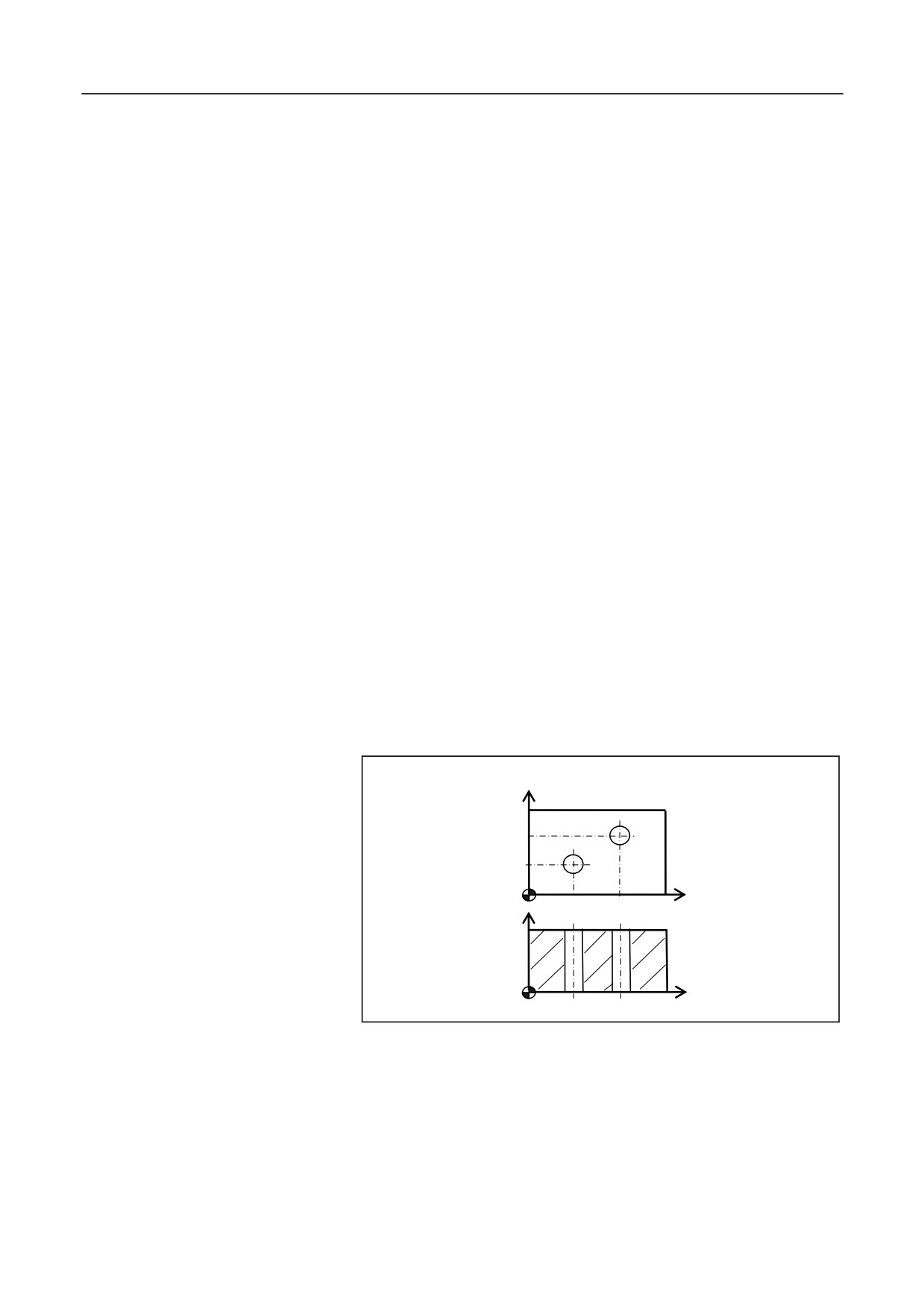
Conduct boring of the holes as shown in the figure below:
Y
30
15
X
20
40
Z
15
X
%3351
N10 G92 X0 Y0 Z80
N15 M03 S600
N20 G98 G85 G91 X20 Y15 G90 R20 Z-3 L2 F100
183
12. Fixed Cycle
N30 G90 G00 X0 Y0 Z80
N40 M30
184

12. Fixed Cycle
12.1.13 Boring Cycle (G86)
Description
The operation specified by G86 is similar as G81. In the G86 mode, the
spindle stops at the hole bottom and the tool exits rapidly. The command
is used to bore the holes which have low requirement for precision.
Format
(G98/G99) G86 X_ Y_ Z_ R_ F_ L_;
Parameter
Description
X Y
The absolute position of the hole for absolute
programming (G90), or the distance from the current
tool position to the hole for incremental programming
(G91).
Z
The absolute position of the hole bottom for absolute
programming (G90), or the distance from the hole
bottom to the point R for incremental programming
(G91)
R
The absolute position of the point R for absolute
programming (G90), or the distance from the point R to
the initial plane for incremental programming (G91).
F
Cutting feed speed.
L
The repeat count
(Generally used for multi-hole
machining to simplify programming. It is optional
when L=1.)
Operation procedure
1. The tool moves rapidly to the point B over the hole center.
2. Move rapidly to the point R, close to the workpiece.
3. Conduct boring downward at the speed of F.
4. Reach the hole bottom of point Z.
5. The spindle stops rotation.
6. Exit upward rapidly to the point R (G99) or B (G98).
7. The spindle restores clockwise rotation.
Attention
1. If the movement amount of Z is zero, the command is not executed.
2. The G86 command data is saved as modal data.
185
12. Fixed Cycle
3. The boring axis must be the Z axis.
4. The point Z must be lower than the plane of point R; otherwise, an
alarm will be reported.
Example
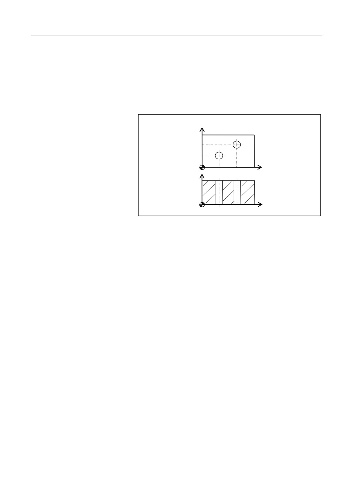
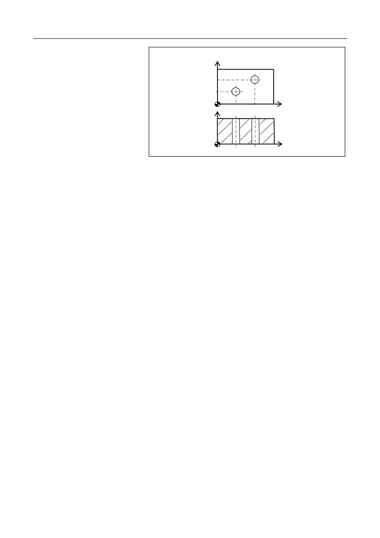
Conduct boring of the hole as shown in the figure below:
Y
30
15
X
20
40
Z
15
X
%3353; Reaming with a reamer
N10 G92 X0 Y0 Z80
N15 G98 G86 G90 X20 Y15 R20 Z-2 F200
N20 X40 Y30
N30 G90 G00 X0 Y0 Z80
N40 M30
186
12. Fixed Cycle
12.1.14 Anti-Boring Cycle(G87)
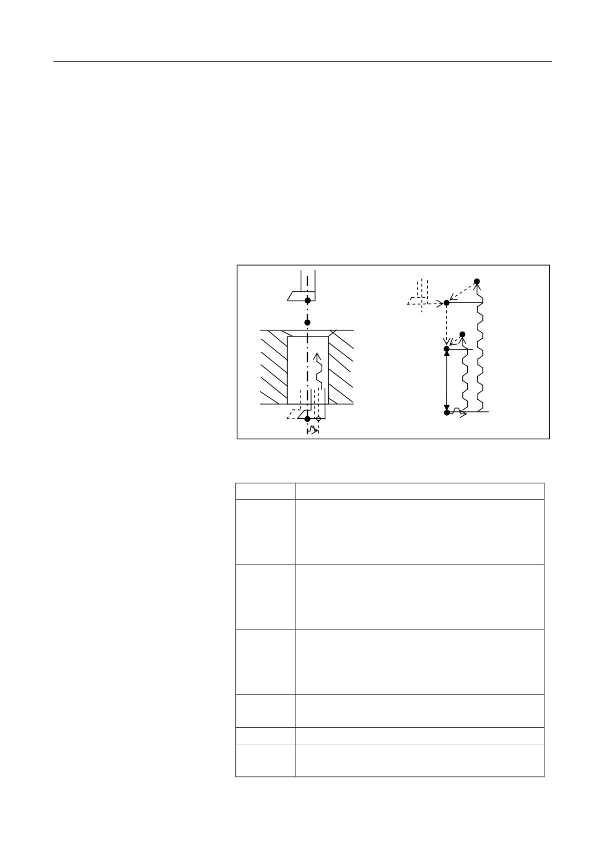
Description
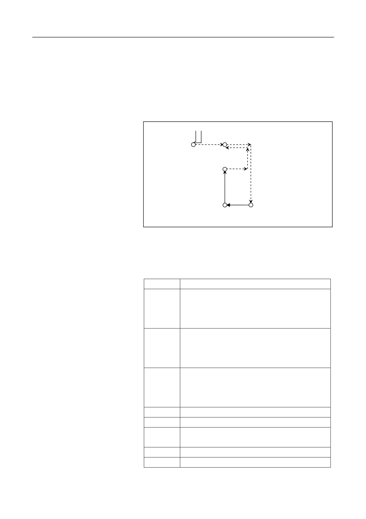
The instruction is generally used to bore holes which are smaller at the
upper part and larger at the lower part. The hole bottom point Z is
generally above the reference point R, which is different from other
instructions.
Initial point
Offset (I, J)
Positioning point R
Point Z
Point R
Reverse offset (I, J)
Format
(G98/G99) G87X_ Y_ Z_ R_ I_ J_ P_ F_ L_;
Parameter
Description
X Y
The absolute position the hole for absolute
programming (G90), or the distance from the current
tool position to the hole for incremental programming
(G91).
Z
The absolute position of the hole bottom along Z axis
for absolute programming (G90), or the distance from
the hole bottom to the point R for incremental
programming (G91)
R
The absolute position of the point R along Z axis for
absolute programming (G90), or the distance from the
point R to the initial plane for incremental
programming (G91).
I
Offset value along X axis.
J
Offset value along Y axis.
P
The duration that the tool remains at the hole bottom.
Unit: millisecond.
F
Cutting feed speed.
L
The repeat count (Generally used for multi-hole
187
12. Fixed Cycle
machining, and therefore X or Y is incremental value.
It is optional when L=1.)
188
12. Fixed Cycle
Operation procedure
1. The tool moves rapidly to the point B over the hole center.
2. The spindle conducts orientation and stops rotation.
3. The boring tool rapidly moves away from the tool nose with the
distance specified by I or J.
4. Move rapidly to the point R.
5. Move rapidly in the positive direction of the tool nose with the
distance specified by I or J, and the tool moves back to the hole
center specified by X, Y.
6. The spindle rotates in the clockwise direction.
7. Conduct boring upward at the speed of F, to the point Z at the hole
bottom.
8. Remain at the hole bottom for P milliseconds (The spindle remains
rotation).
9. The spindle conducts orientation and stops rotation.
10. The boring tool rapidly moves away from the tool nose with the
distance specified by I or J.
11. Exit upward rapidly to the point B (G98).
12. Move rapidly in the positive direction of the tool nose with the
distance specified by I or J, and the tool moves back to the hole
center point B.
13. The spindle restores the clockwise rotation.
Attention
1. The boring axis must be the Z axis.
2. If the movement amount of Z is zero, the command is not executed.
3. The point Z must be higher than the plane of point R; otherwise, an
alarm will be reported.
4. The G87 command data is saved as modal data.
5. Only G98 can be used for G87.
6. Before using the command of G87, use the corresponding M
command to rotate the spindle.
189
12. Fixed Cycle
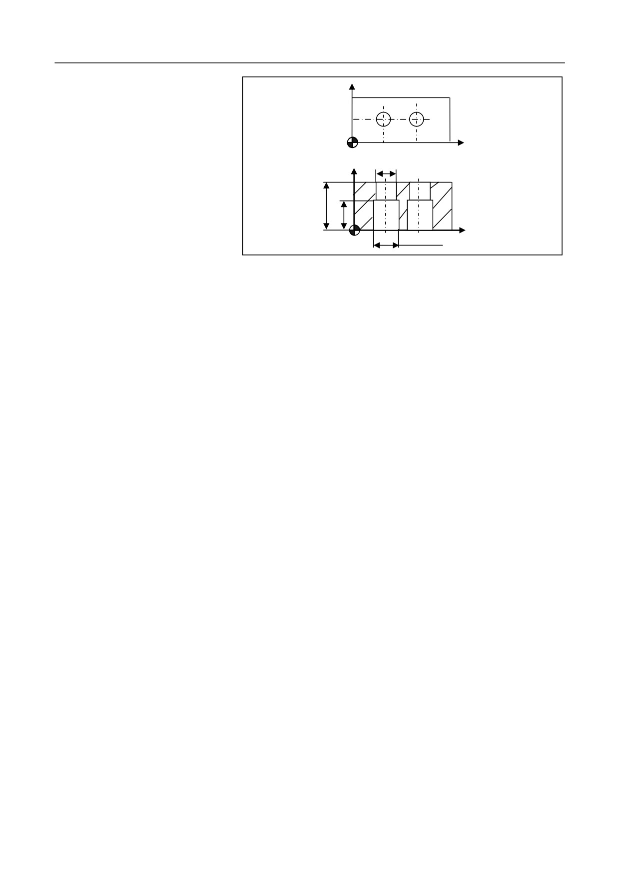
Example
Y
15
X
20
40
2×ĭ20
Z
35
20
X
2×ĭ28
%3355
N10 G92 X0 Y0 Z80
N15 M03 S600
N20 G00 Y15 F200
N25 G98
G87 G91
X20 I5 R-83 P2000 Z23 L2
N30 G90 G00 X0 Y0 Z80 M05
N40 M30
190
12. Fixed Cycle
12.1.15 Boring Cycle (Manual Boring) (G88)
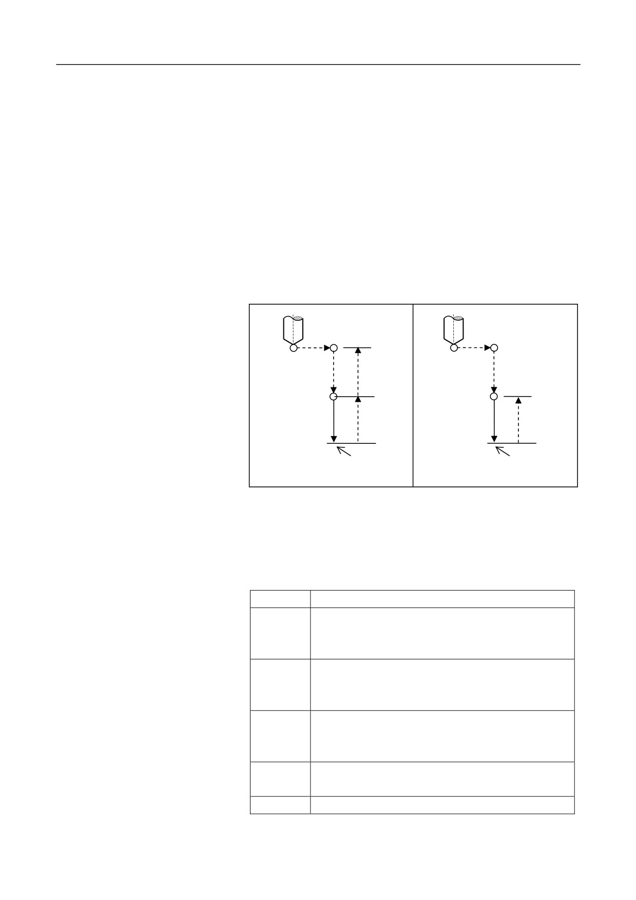
Description
Before boring, this instruction memories the initial point B or reference
point R. When the boring tool automatically processes to the hole bottom,
the machine stops. You may manually change the operation mode to
"Manual", and move the tool upward to the point B or R, and avoid the
workpiece. Then the operation mode is changed back to the automatic
operation mode. Start the program again, and the tool returns back to the
point B or R. This instruction is generally used for precise boring with
milling machines, without calling the spindle exact stop function.
Return to point
B; spindle CW
Initial point B
Reference point R
Return to point
R; spindle CW
Reference point R
G98
G99
Hole bottom point
Hole bottom
Z
Remains at the hole bottom
point Z
and the spindle stops
Format
G98 (G99) G88 X_ Y_ Z_ R_ P_ F_ L_
Parameter
Description
X Y
The absolute position of the hole for absolute
programming (G90), or the distance from the current
tool position to the hole for incremental programming
(G91).
Z
The absolute position of the hole bottom along axis Z
for absolute programming (G90), or the distance from
the hole bottom to the point R for incremental
programming (G91).
R
The absolute position of the point R along Z axis for
absolute programming (G90), or the distance from the
point R to the initial plane for incremental
programming (G91).
P
The duration that the tool remains at the hole bottom.
Unit: millisecond.
F
Boring feed speed.
L
The repeat count
(Generally used for multi-hole
machining, and therefore X or Y is incremental value.)
191
12. Fixed Cycle
Operation procedure
1.
The tool moves rapidly to the point B over the hole center.
2.
Move rapidly to the point R, close to the workpiece surface.
3.
Conduct boring downward at the speed of F, to the point Z at the
hole bottom.
4.
Remain at the hole bottom for P seconds (The spindle remains
rotation).
5.
The spindle stops rotation.
6.
Manually move the tool until it is over the point R (G99) or B
(G98).
7.
Press Start in the auto operation mode, the tool rapidly moves to
the point R (G99) or B (G98).
8.
The spindle restores the clockwise rotation.
Attention
1.
The boring axis must be the Z axis.
2.
If the movement amount of Z is zero, the command is not executed.
3.
The point Z must be lower than the plane of point R; otherwise, an
alarm will be reported.
4.
The G88 command data is saved as modal data.
5.
If G99 is used, manually move the tool to the place over the point of
R.
6.
If G98 is used, manually move the tool to the place over the point of
B.
7.
Before using the command of G88, use the corresponding M
command to rotate the spindle.
192
12. Fixed Cycle
Example
Y
30
15
X
20
40
Z
35
X
%3357; Drilling with a single-margin boring tool
N10 G54
N12 M03 S600
N15 G00 X0 Y0 Z80
N20 G98G88G91X20Y15R-42P2000Z-40L2F100
N30 G00 G90 X0 Y0 Z80
N40 M30
193
12. Fixed Cycle
12.1.16 Boring Cycle (G89)
Description
This operation specified by the command G89 is almost the same as that
of G86. In the G89 mode, the spindle pauses at the hole bottom. Before
specifying G89, use auxiliary function the M command to rotate the
spindle. When the G89 command and M command are specified in the
same block, the system executes the M command while the first
positioning movement is performing , and then conducts the next boring.
If the repeat count L is specified, the system executes the M command
only for the first boring hole.
The operation specified by G89 is as shown below:
Initial plane
Plane of point R
Plane of point R
Point R
Point R
Point Z
Point Z
Pause
Pause
G89 (G98)
G89 (G99)
This cycle is used for boring.
Format
(G98/G99) G89 X_ Y_ Z_ R_ P_ F_ L;
Parameter
Description
X Y
The absolute position of the hole for absolute
programming (G90), or the distance from the current tool
position to the hole for incremental programming (G91).
Z
The absolute position of the hole bottom for absolute
programming (G90), or the distance from the hole bottom
to the point R for incremental programming (G91).
R
The absolute position of the point R for absolute
programming (G90), or the distance from the point R to
the initial plane for incremental programming (G91).
P
The duration that the tool remains at the hole bottom.
Unit: millisecond.
F
Cutting feed speed.
194
12. Fixed Cycle
L
The repeat count
(Generally used for multi-hole
machining, and therefore X or Y is an incremental
value.)
195
12. Fixed Cycle
Attention
1. The boring axis must be the Z axis.
2. The point Z must be lower than the plane of point R; otherwise, an
alarm will be reported.
3. The G89 command data is saved as modal data.
4. G89 is similar as G86, but with a pause at the hole bottom.
5. If the movement amount of Z is zero, this command is not executed.
6. Before using the command of G89, use the corresponding M
command to rotate the spindle.
Example
M3 S1000; The spindle starts rotation.
G90 G99 G89 X300 Y-250 Z-150 R-120 P1000 F120; Conduct
positioning, and conduct boring for hole 1, return to the point R and then
pauses at the hole bottom for one second
Y-550; Conduct positioning, and conduct boring for hole 2; return
to the point R
Y-750; Conduct positioning, and conduct boring for hole 3; return to the
point R
X1000; Conduct positioning, and conduct boring for hole 4; return to the
point R
Y-550; Conduct positioning, and conduct boring for hole 5; return to the
point R
G98 Y-750; Conduct positioning, and conduct boring for hole 5; return to
the initial plane
G80 G28 G91 X0 Y0 Z0; Cancel boring and return to the reference point
M5; The spindle stops rotation.
196
12. Fixed Cycle
12.1.17 Cancel Fixed Cycle (G80)
Description
This command is used to cancel the fixed cycle for drilling.
Format
G80
Attention
1.
Cancel all fixed cycles for the drilling and then restore the normal
operation.
2.
Cancel the R and Z planes.
3.
Other drilling parameters are also canceled.
197
12. Fixed Cycle
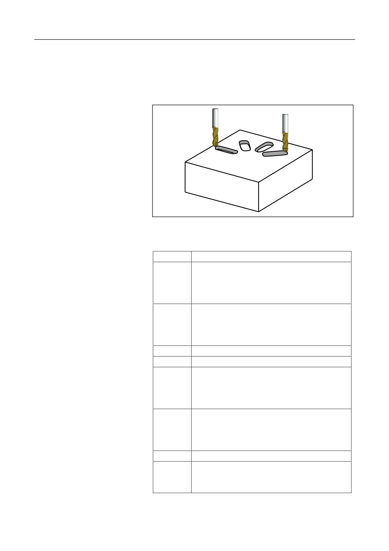
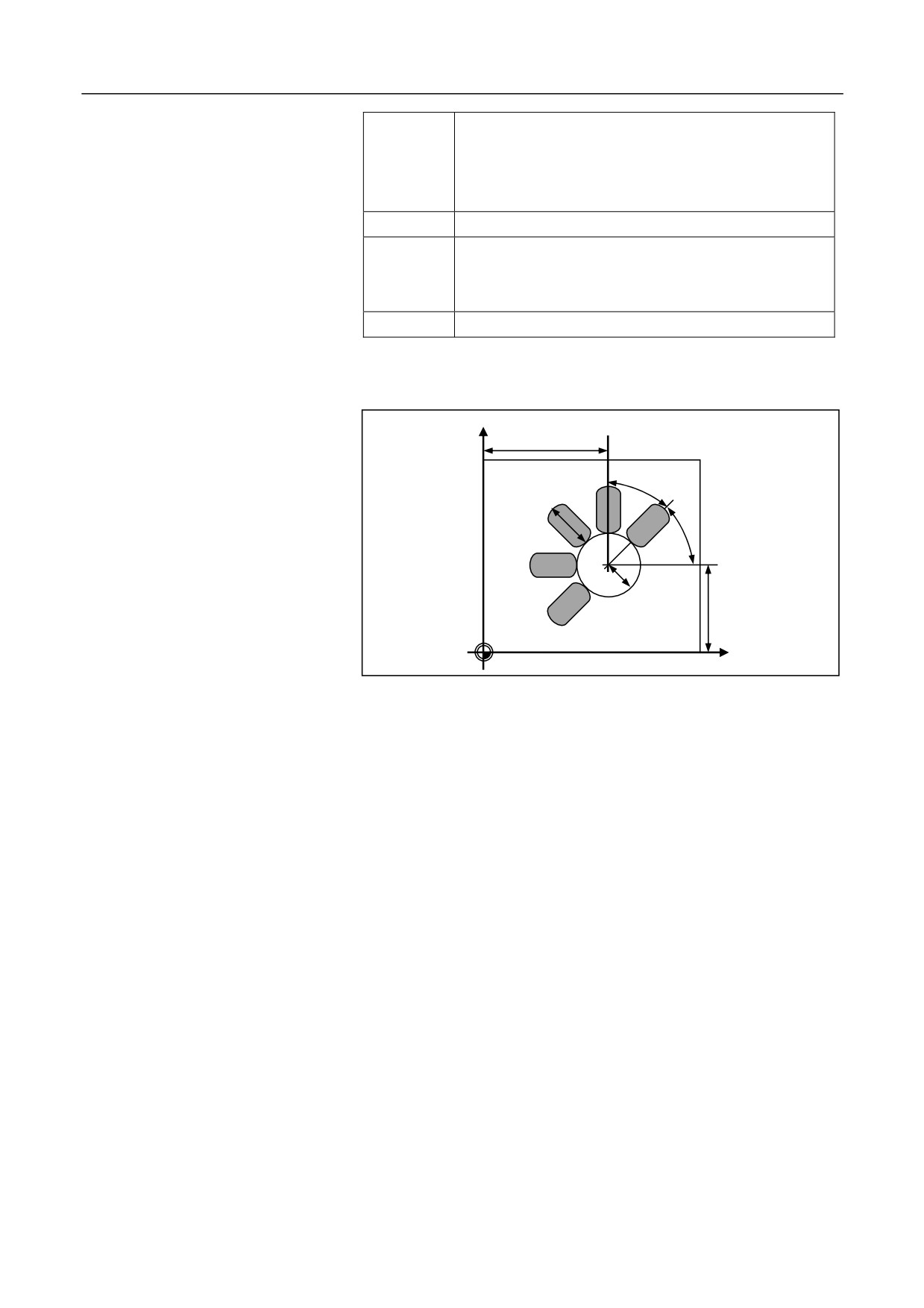
12.1.18 Arc Groove Cycle (Type 1) (G181)
Description
This command is used to process the grooves arranged according to an
arc. The groove width is defined by the tool diameter.
(G98/G99) G181 R_ Z_ N_ K_ X_ Y_ I_ A_ B_ F_ Q_ V_
Format
Parameter
Description
The coordinate value of the reference point R for
absolute programming, or the distance from reference
R
point R to the initial plane for incremental
programming.
The coordinate value of the groove bottom for absolute
programming, or the incremental value from the
Z
groove bottom to the reference point R for incremental
programming.
N
The number of grooves (It is optional when N=1)
K
The length of the groove.
The center of the arc formed by the grooves. The first
axis coordinate of the current plane for absolute
X
programming, and the incremental value relative to the
start point for incremental programming.
The center of the arc formed by the grooves. The
second axis coordinate of the current plane for absolute
Y
programming, and the incremental value relative to the
start point for incremental programming.
I
The radius of the arc formed by the grooves.
Start angle (-180 to 180 degrees, positive in the CCW
A
direction and negative in the CW direction. It is
optional when A=0)
198
12. Fixed Cycle
Incremental angle (It is optional when B=360/N. A
positive B value indicates the milling in the CCW
B
direction; a negative B value indicates the milling in
the CW direction.
F
Milling speed.
The maximum feed depth each time (It is optional
Q
when Q= groove depth , cutting to the bottom for a
time).
V
Tool radius.
Parameter graph
Y
X
B
K
A
I
Y
X
Operation procedure
1.
Select a random start point from which the tool may move to each
groove without any collision.
2.
Go to the reference position R over the near-end of the first groove
from the start point. The near-end indicates the end near to the
center of the arc groove. The groove specified by the start angle A
will be processed firstly.
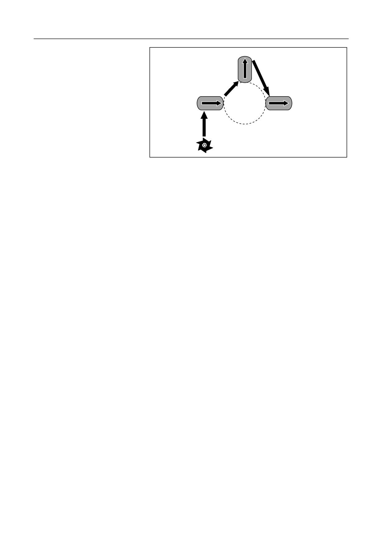
3.
Feed downward at the milling feed rate to the defined depth, and
then conduct milling back and forth until the bottom is machined.
Conduct deep feed at the groove end.
4.
On the application axis (generally Z axis), exit the tool to the
reference point R. Select the shortest path to rapidly move to the
end of the next groove, and conduct milling back and forth until the
bottom is machined.
5.
After completing the last groove, exit the tool to the initial point B
or the reference point R based on the current modal G98 or G99,
199
12. Fixed Cycle
and then the cycle ends.
N=3
Milling in the
A=180
CCW direction B=-90
Attention
1.
The groove number N must be a non-negative integer. If not, the
negative symbol
(-) will be ignored, and the number will be
rounded.
2.
The maximum feed depth is specified by the value of Q. If the
groove depth is not divisible by Q, the final cut depth will be less
than Q.
3.
The milling direction for each groove is related to the symbol of B.
If the value of B is positive, the system starts the milling from the
first groove to the last in the CCW direction; if the value of B is
negative, the system starts the milling in the CW direction. If B is
not specified, the system will automatically derive B from B=360/N,
and conduct milling in the CCW direction.
4.
The value of K, I, and Q should be non-negative values. If not, the
system will ignore the negative symbol.
5.
Rotate the spindle before executing the cycle. For alarm information,
see section 12.1.26.
200
12. Fixed Cycle
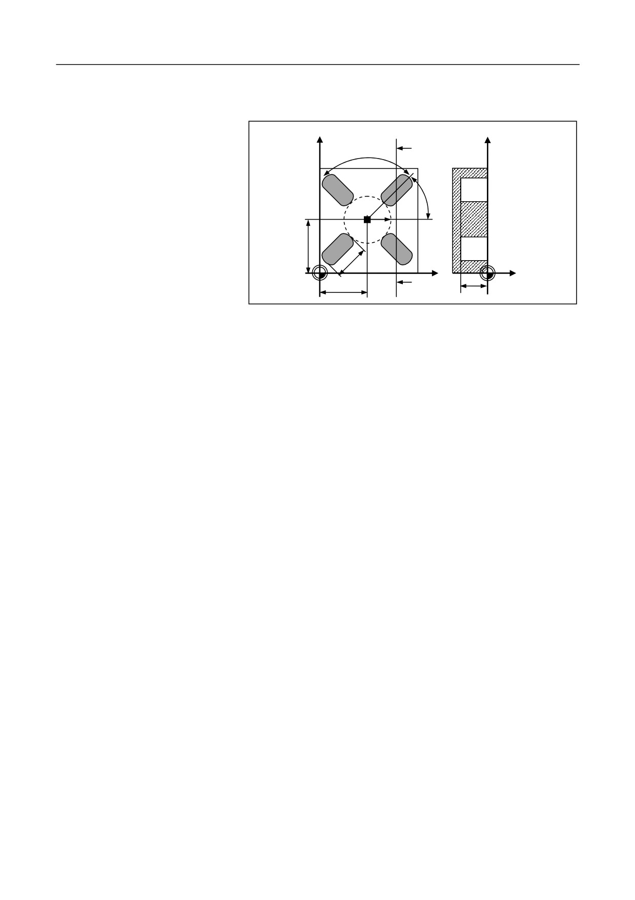
Example
grooves as shown in the figure below: Groove length 30 mm; groove
depth 23 mm; feed depth 6 mm
Y
Y
A
A-B
90 degrees
45
degrees
20
45
30
B
X
23
Z
40
%0526
N10
G54 X0 Y0 Z5
N20
G17 G90
N30
T10
N40
M06
N50
M03 S600
N60
G181 R0 Z-23 N4 K30 X40 Y45 I20 A45 B90 F100 Q6 V5
N70
M30
Conduct
milling
for
four
rectangle
201
12. Fixed Cycle
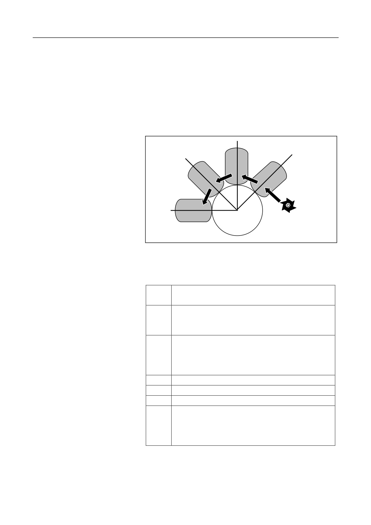
12.1.19 Arc Groove Cycle (Type 2) (G182)
Description
The instruction is used to process grooves which are arranged in an
annular array. The longitudinal shaft of these grooves turn up radially.
The instruction is different from G181, as the groove width can be
specified by a parameter, but not be defined by the tool diameter.
This cycle can be specified for rough and finish machining.
G0
G0
G0
G0
(G98/G99)G182 R_Z_N_K_W_X_Y_I_A_B_F_ Q_ E_O_H_U_P_C_D_V_
Format
Para
Description
meter
The coordinate value of the reference point R for absolute
R
programming, or the distance from reference point R to the
initial plane for incremental programming.
The coordinate value of the groove bottom for absolute
programming, or the incremental value from the groove
Z
bottom to the reference point R for incremental
programming.
N
The number of grooves (It is optional when N=1)
K
The length of the groove.
W
The groove width (It is optional when W= tool diameter).
The center of the arc formed by the grooves. The first axis
coordinate of the current plane for absolute programming,
X
and the incremental value relative to the start point for
incremental programming.
202

12. Fixed Cycle
The center of the arc formed by the grooves. The second
axis coordinate of the current plane for absolute
Y
programming, and the incremental value relative to the
start point for incremental programming.
I
The radius of the arc formed by the grooves.
Start angle (-180 to 180 degrees, positive in the CCW
A
direction and negative in the CW direction. It is optional
when A=0)
Incremental angle (It is optional when B=360/N. A positive
B
B value indicates the milling in the CCW direction; a
negative B value indicates the milling in the CW direction.
F
Milling speed for rough machining.
The maximum feed depth for rough machining each time(It
Q
is optical when Q=groove depth -the depth of groove
Parameter graph
bottom left for finish machining).
The finish allowance at the edge of the groove(It is optional
E
when E=0).
The finish allowance in the groove bottom(It is optional
O
when O=0).
The maximum feed depth for finish machining(It is
H
optional when H=Q).
U
Feed speed for finish machining(It is optional when U=F).
Spindle speed for finish machining(It is optional when
P
P=spindle speed before the cycle or default spindle speed).
The direction for milling each groove (It is optional when
C=3)
0:milling in the same direction with the spindle rotation;
C
1:milling in the reversed direction with the spindle
rotation; 2:milling in G02 direction; 3:milling in G03
direction
1:rough machining 2:finish machining (It is optional when
D
D=1).
V
Tool radius.
203
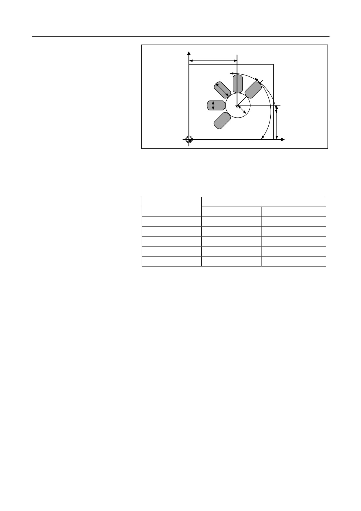
12. Fixed Cycle
Y
X
B
k
A
w
I
Y
X
Before entering the cycle mode, you need to use the command to enable
spindle rotation. The system will calculate the reasonable milling
Milling direction
direction based on the spindle rotation direction (M03/M04) and the
command . See the table below:
Milling direction
Execute M03/M04 before the cycle
(Parameter C)
M03 spindle CW
M04 spindle CCW
0: same direction
G03
G02
1: reversed direction
G02
G03
2: in G02 direction
G02
G02
3: in G03 direction
G03
G03
Left blank
G03
G03
1.
Select the start point , a random start point from which the tool may
move to each groove without any collision.
Operation procedure
2.
Go to the reference point R over the first groove. The groove
specified by the start angle A will be processed firstly.
3.
Rough machining (D=1):
Starting at the groove end, the tool conducts milling from the
middle part to the margin and from the groove surface to the finish
allowance in the milling direction specified by C. Each time the tool
feeds at the same point of the groove end until it reaches finish
allowance in the groove bottom.
Finish machining (D=2):
Conduct finish machining for the groove wall and then the groove
bottom. Conduct milling from the middle part to the defined groove
margin in the milling direction specified by the parameter C, and
then back to the the same start position, conduct milling downward
to the groove bottom
204
12. Fixed Cycle
4.
After completing a groove, exits the tool to the reference point R.
Rapidly move to the near-end of the next groove, and repeat step 3
until completing the last groove.
5.
Exits the tool to the initial point B or the reference point R with
G98 or G99, and then the cycle ends.
1.
The tool radius cannot exceed the specified groove width W;
otherwise, an alarm will be reported.
2.
The groove number N must be a non-negative integer. If not, the
Attention
system will ignore the negative symbol, and conduct rounding for
the non-integer.
3.
Q and H both specify the maximum feed depth . If the groove depth
is not divisible by Q or H, the final cut depth will be less than Q or
H.
4.
The milling direction for each groove is specified by the parameter
C. The milling direction between grooves is specified by the
parameter B. If the value of B is positive, the system starts the
milling from the first groove to the last in the CCW direction; if the
value of B is negative, the system starts the milling in the CW
direction. If B is not specified, the system will automatically derives
B from B=360/N, and conduct milling in the CCW direction.
5.
The values of parameter K, W, I, E, O, H and Q should be
non-negative values. If the value is negative, the system will ignore
the negative symbol.
6.
Rotate the spindle Before executing the cycle. The finish allowance
(E) specified for the groove margin cannot exceed half of the
groove width (W/2), and the finish allowance (O) specified for the
groove bottom cannot exceed the groove depth; otherwise, an alarm
will be reported. For more alarm information, see section 12.1.26.
205
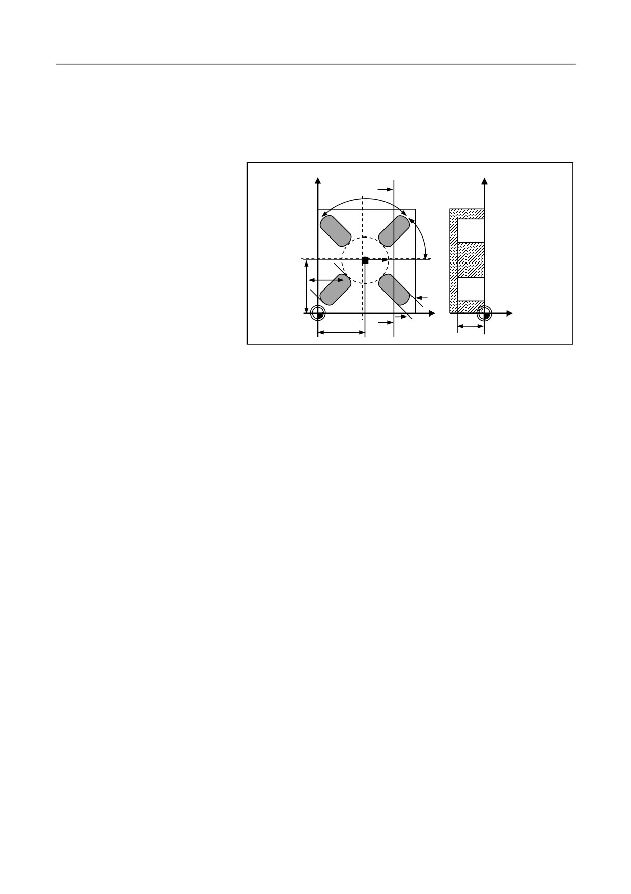
12. Fixed Cycle
Example
Conduct milling for four grooves as shown in the figure below:
Groove length 30 mm; groove width 15 mm; groove depth 23 mm; finish
allowance
0.5 mm; milling direction G02; feed depth for rough
machining 6 mm; tool radius: 5 mm
Y
A
X
90 degrees
A-B
45°
20
30
45
15
B
X
23
Z
40
%0527
N10 G54 G17 G90
N20 T10
N30 M06
N40 M03 S600
N50 G182R5Z-23N4K30X40Y45W15I20A45B90F100Q6E0.5O0.5C2 V5
N60 M30
206
12. Fixed Cycle
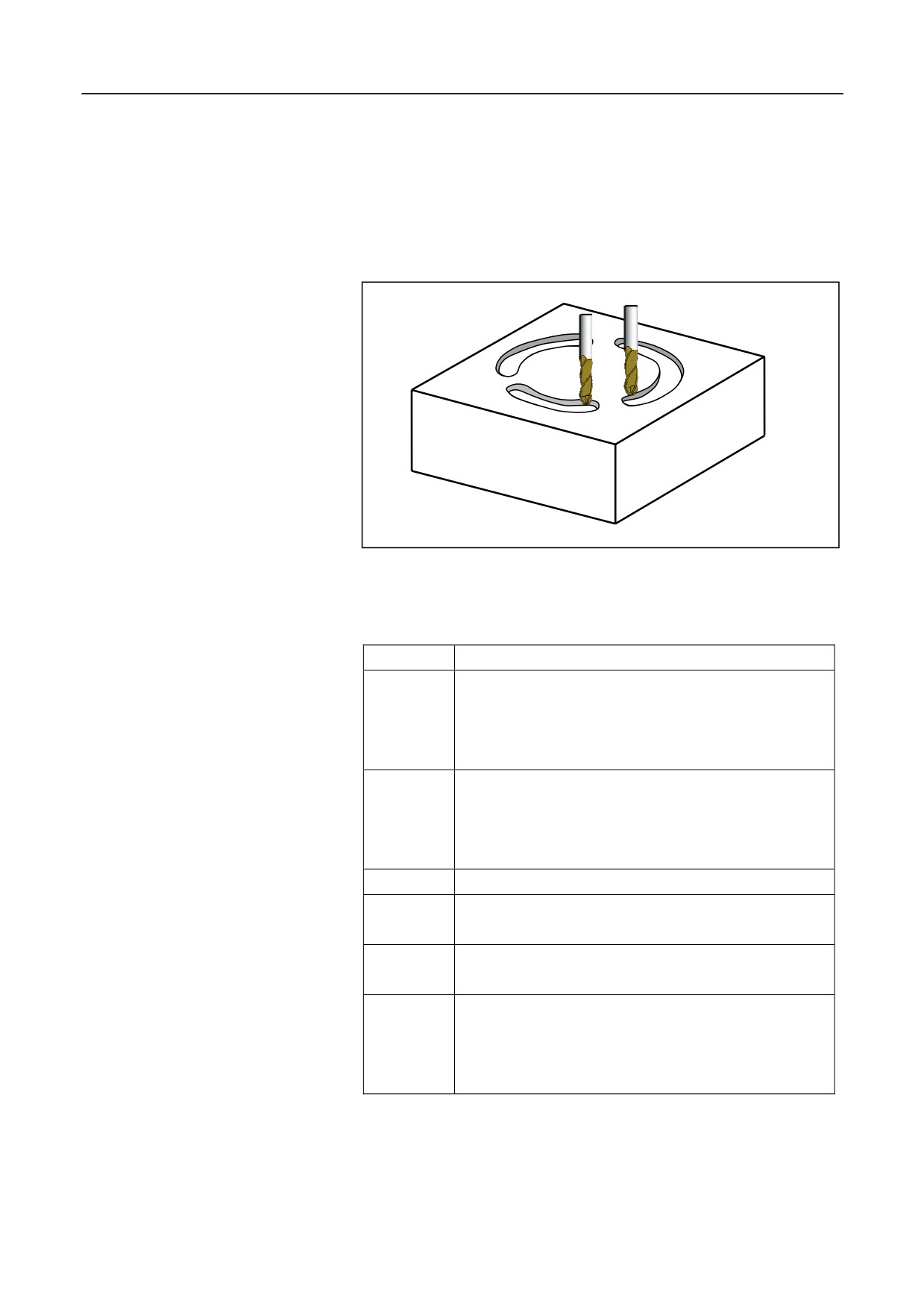
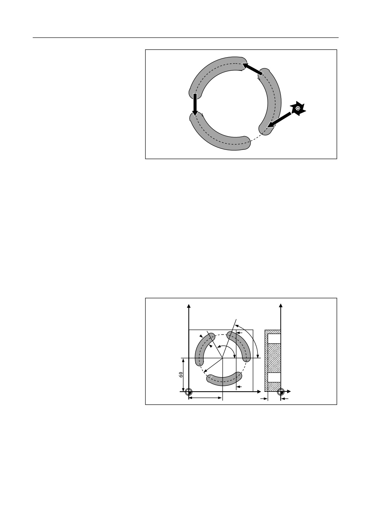
12.1.20 Circumference Groove Milling Cycle (G183)
Description
This cycle is used to process circumference grooves distributed in a
circle shape. You may specify roughing, finishing or comprehensive
machining.
(G98/G99)G183R_Z_N_K_W_X_Y_I_A_B_F_ Q_E_O_H_U_P_C_D_V_
Format
Parameter
Description
The coordinate value of the reference point R for
absolute programming, or the distance from reference
R
point R to the initial plane for incremental
programming.
The coordinate value of the groove bottom for absolute
programming, or the incremental value from the
Z
groove bottom to the reference point R for incremental
programming.
N
The number of grooves (It is optional when N=1 ).
The angle of groove length (0 to 360 degrees. Unit:
K
degree).
The width of the groove (It is optional when W= tool
W
diameter ).
The center of the circle rounded by the grooves. The
first axis coordinate of the current plane for absolute
X
programming, and the incremental value to the start
point for incremental programming.
207

12. Fixed Cycle
The center of the circle rounded by the grooves. The
second axis coordinate of the current plane for absolute
Y
programming, and the incremental value to the start
point for incremental programming.
I
The radius of the circle rounded by the grooves.
Start angle (-180 to 180 degrees, positive in the CCW
A
direction and negative in the CW direction. It is
optional when A=0.)
Incremental angle (It is optional when B=360/N ; a
positive B value indicates the milling in the CCW
B
direction while a negative B value indicates the milling
in the CW direction.
F
Milling speed during rough machining.
The maximum feed depth for each time during rough
Q
machining (It is optional when Q= groove depth- finish
ing allowance of the groove bottom).
The finishing allowance of the groove margin (It is
E
optional when E=0).
The finishing allowance in the groove bottom (It is
O
optional when O=0).
The feed rate for finish machining (It is optional when
U
U=F).
The spindle speed for finish machining (It is optional
P
when P= the spindle speed before cycle ).
The direction for milling each groove (It is optional
when C=3)
0:milling in the same direction with the spindle
C
rotation; 1:milling in the reversed direction with the
spindle rotation; 2:milling in G02 direction; 3:
milling in G03 direction
Machining type (It is optional when D=1)
D
1: rough machining;
2: finish machining
V
Tool radius.
208
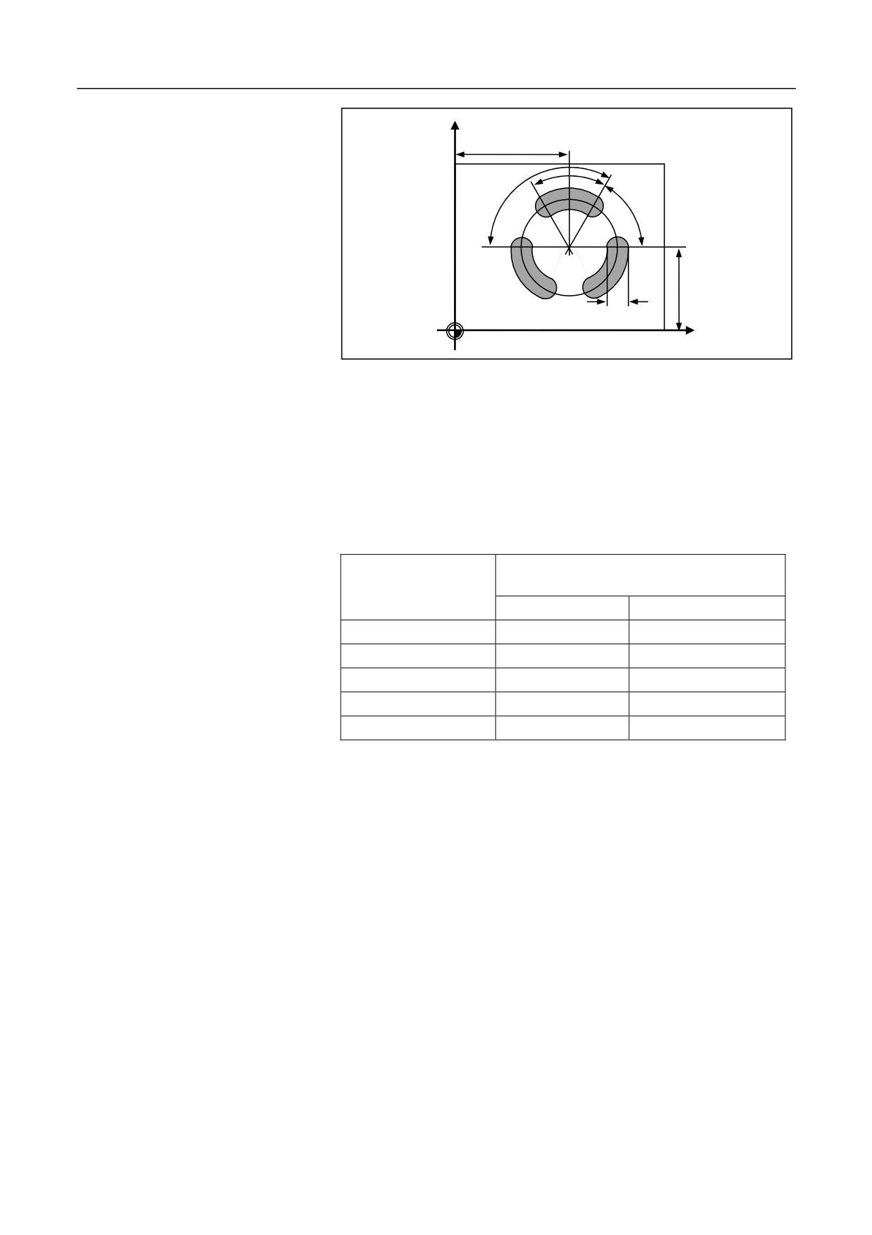
12. Fixed Cycle
Parameter graph
Y
X
B
k
A
w
Y
X
Milling direction
Before entering the cycle mode, you need to use the command to enable
spindle rotation. The system will calculate the reasonable milling
direction (M03/M04) based on the spindle rotation and the command .
See the table below:
Milling Direction
Execute M03/M04 before the cycle
(Parameter C)
M03 spindle CW
M04 spindle CCW
0: same direction
G03
G02
1: reversed direction
G02
G03
2: in G02 direction
G02
G02
3: in G03 direction
G03
G03
Left blank
G03
G03
Operation procedure
1.
During the cycle, use G00 to move to the reference plane R.
2.
Conduct milling for the current groove from middle part to the edge.
The operation procedure is similar as that of G182.
3.
After completing a groove, exit the tool to the reference plane and
move to the next groove.
4.
After completing all grooves, exit the tool with the G98 or G99
command, and then the cycle ends.
209
12. Fixed Cycle
G0
G0
G0
Example
Conduct milling for three grooves shown in the figure below:
Circle center: (X60, Y60); radius on the XY plane: 42 mm; groove width:
15 mm; groove length angle: 70 degrees; groove depth: 23 mm; start
angle: 0 degree; incremental angle: 120 degrees; finishing allowance on
the groove contour: 0.5 mm; feed depth: 6 mm; tool radius 5 mm
The spindle speed and feed rate for rough and finish machining are the
same. The finish machining is completed with one cut.
See the figure below:
Y
Y
A-B
A
70°
15
120°
42
B
60
X
Z
23
%0528
N10 G54 G17 G90
N20 T10
N30 M06
N40 M03 S600
210
12. Fixed Cycle
N50 G00 X60 Y60 Z5
N60 G183R2Z-23N3K70W15X60Y60I42A70B120F100Q6E0.5O0.5V5
N70 M30
211
12. Fixed Cycle
12.1.21 Rectangular Groove Cycle (G184)
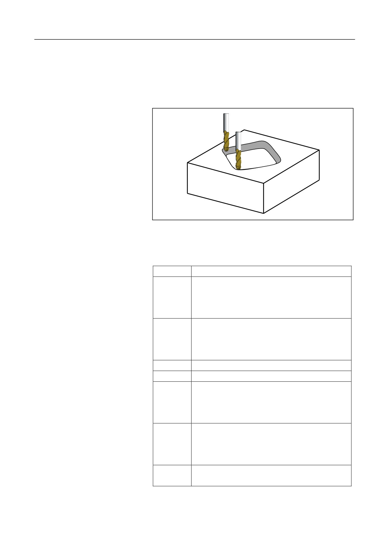
Description
This cycle is used for the rough and finish machining of rectangular
grooves with rounded corners.
Format
(G98/G99)G184R_Z_K_W_X_Y_I_A_F_ Q_E_O_H_U_P_C_D_V_
Parameter
Description
The coordinate value of the reference point R for
absolute programming, or the distance from reference
R
point R to the initial plane for incremental
programming.
The coordinate value of the groove bottom for absolute
programming, or the incremental value from the
Z
groove bottom to the reference point R for incremental
programming.
K
The length of the groove.
W
The width of the groove.
The center of the groove. The first axis coordinate of
the current plane for absolute programming, and the
X
incremental value to the start point for incremental
programming.
The center of the groove. The second axis coordinate
of the current plane for absolute programming, and the
Y
incremental value to the start point for incremental
programming.
The arc radius of the rounded corner (It can be left
I
blank or specified to 0 when I=W/2 ).
212

12. Fixed Cycle
The angle formed by the long side of the rectangle
A
groove and the first positive axis (It is optional when
A=0.).
F
Milling speed during rough machining.
The maximum feed depth for each time during rough
Q
machining
(It is optional when Q= groove depth-
finishing allowance of the groove bottom).
The finishing allowance of the groove margin (It is
E
optional when E=0).
The finishing allowance of the groove bottom (It is
O
optional when O=0).
The maximum feed rate for finish machining (It is
H
optional when U=Q ).
The feed rate for finish machining (It is optional when
U
U=F ).
The spindle speed for finish machining (It is optional
P
when P= the spindle speed before cycle or the default
spindle speed).
The direction for milling each groove (It is optional
when C=3)
0:milling in the same direction with the spindle
C
rotation; 1:milling in the reversed direction with the
spindle rotation; 2:milling in G02 direction; 3:
milling in G03 direction
Machining type (It is optional when D=1)
D
y
1: rough machining
y
2: finish machining
V
The tool radius.
213