HNC-818. User Manual - page 9
12. Fixed Cycle
value.
K
The relative distance from the cutting start point B
to the end point C along the Z axis.
F
Feed speed (indicates to move at the speed
specified by F) (mm/min)
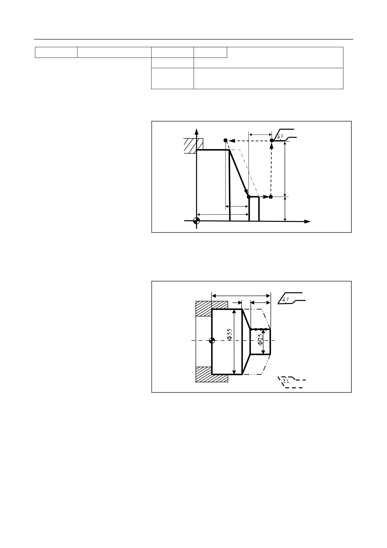
The cutting process is along the path AĺBĺCĺDĺA. See the figure
below:
w
+X
B
1R
A
2F
4R
u/2
3F
k
C
D
z
x/2
+Z
Conduct machining for the workpiece as shown in the figure below: use
Example
G81 programming; The dotted lines indicate the workpiece.
33.5
8
3
%3323
N1 T0101; Establish the coordinate system, and choose tool 1
245
12. Fixed Cycle
N2 G00 X60 Z45; Move to the cycle
start point
N3 M03 S460; Rotate the spindle in
the clockwise direction
N5 X25 Z29.5 K-3.5; Each tool depth is 2 mm.
N4 G81 X25 Z31.5 K-3.5 F100;
N6 X25 Z27.5 K-3.5; Conduct each cutting at the start point; 5 mm away
Conduct the first cycle with tool
from the outer circle of workpiece; the value of K is -3.5.
depth 2 mm
N7 X25 Z25.5 K-3.5; Conduct the fourth cycle with tool depth 2 mm
N8 M05; Stop the spindle
N9 M30; End the main program and reset.
246

12. Fixed Cycle
12.2.3 Thread Cutting Cycle (G82)
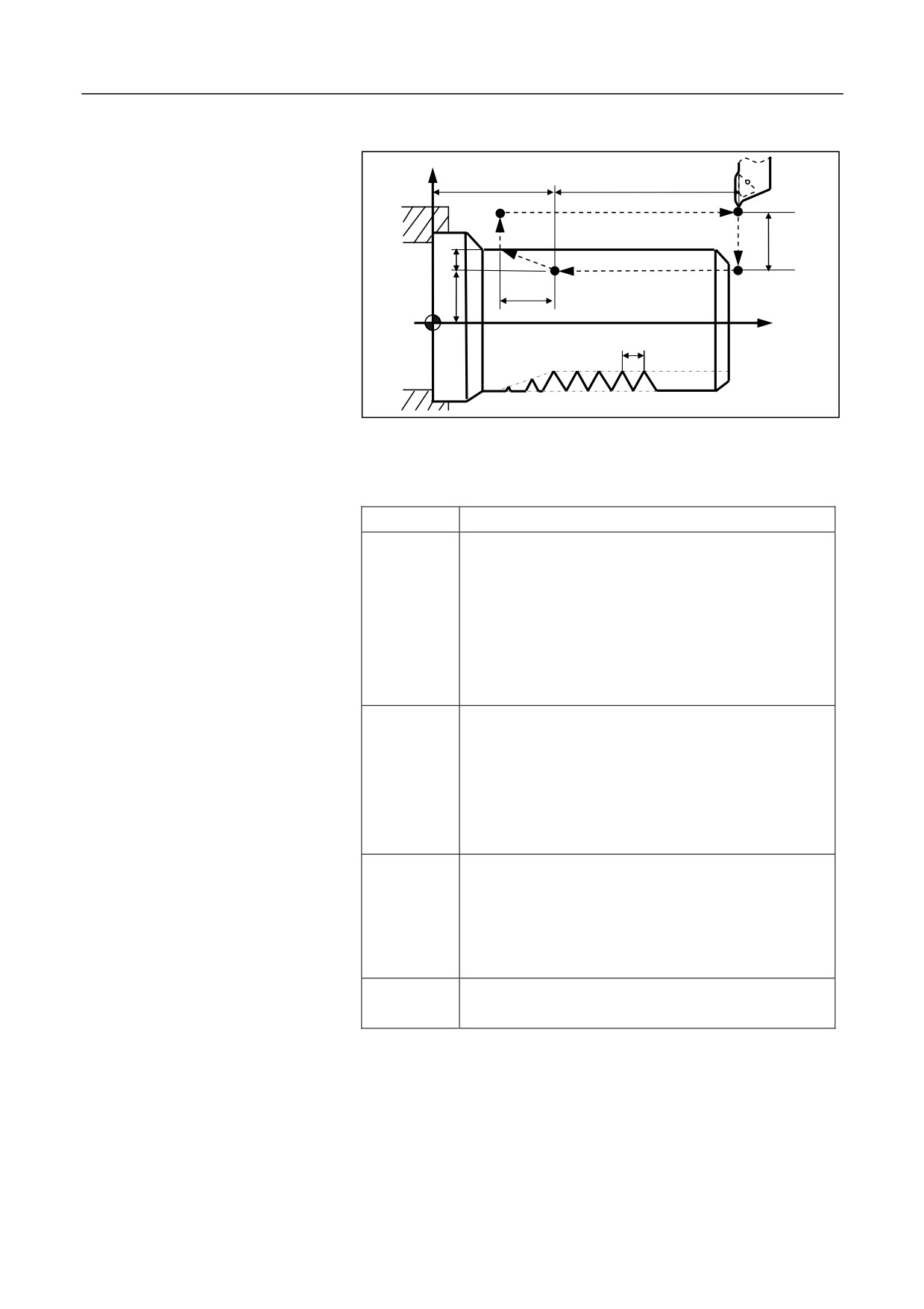
This cycle can be used for machining straight thread or conical thread.
Straight thread cutting cycle
G82 X_/U_ Z_/W_ R_ E_ C_ P_ F_
Parameter
Description
X /U Z/W
The thread end point C at the workpiece coordinate
system for absolute value programming; The relative
distance from the thread end point C to the cycle start
point A for the incremental value programming. Use U
and W to express them in the blueprint and the direction
of path 1 and 2 determines whether it is a positive or a
negative value.
R E
The retreat of tailstock for thread cutting. R and E are
vectors. R indicates the retreat along the Z axis
direction, and E indicates the retreat along the X axis
direction. A positive value indicates the retreat
towards the positive X/Z direction, while a negative
value indicates the retreat towards the negative X/Z
direction. R and E can be left blank, which indicates
that there is no tailstock retreat function.
C
The number of threads. The value 0 or 1 indicates
single thread cutting.
P
During the single thread cutting, it inidcates the spindle
rotation angle between the spindle reference pulse and
the starting point of the cutting
(default value
0);
During multi-thread cutting, it indicates the spindle
rotation angle between the cutting start points of the
adjacent thread.
F
Metric thread lead (mm/r)
247
12. Fixed Cycle
The tool moves along the path AĺBĺCĺDĺA. See the figure below:
X
z
w
D
4R
A
3R
u/2
1R
e
2F
C
B
r
x/2
+Z
L
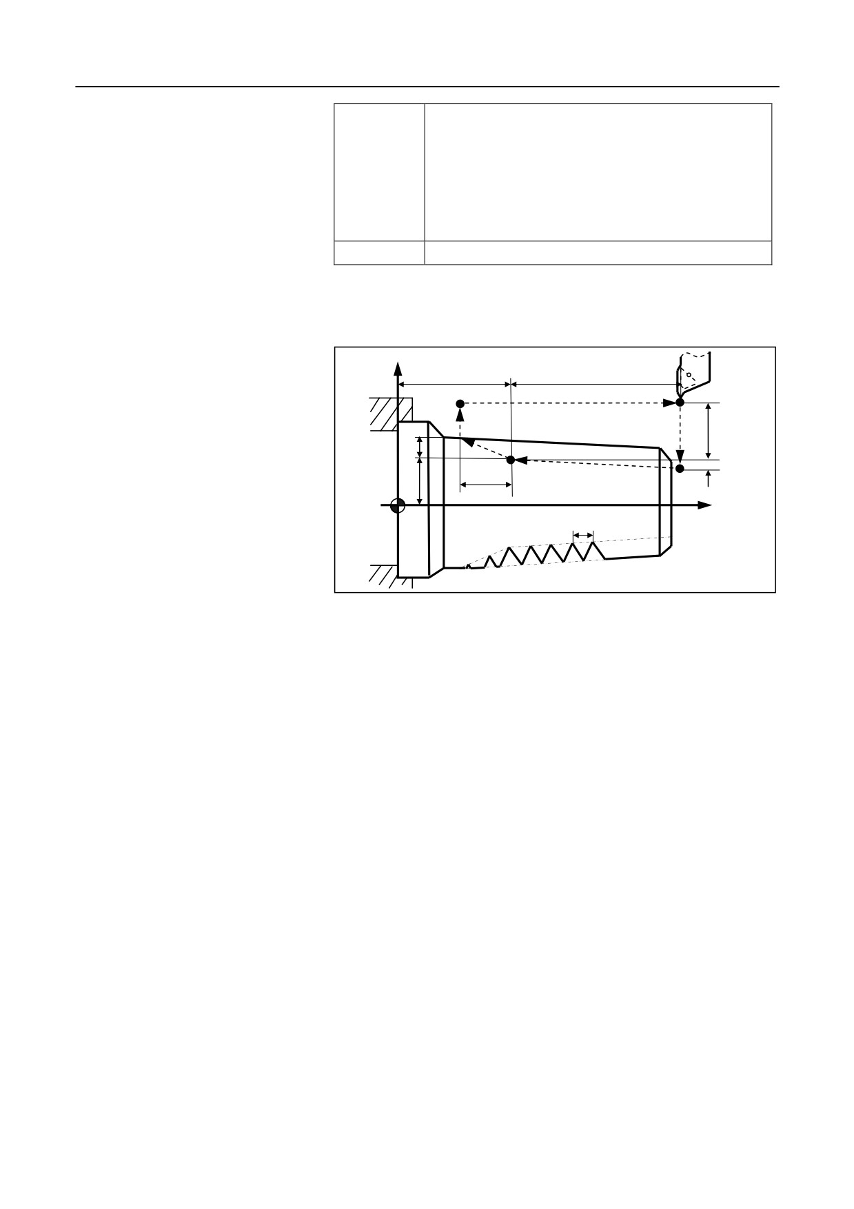
Conical thread cutting cycle
G82 X_/U_ Z_/W_ I_ R_ E_ C_ P_ F_
Parameter
Description
X /U Z/W
The thread end point C at the workpiece coordinate
system for absolute value programming; The relative
distance from the thread end point C to the cycle start
point A for the incremental value programming. Use
U, W to express them in the blueprint and the direction
of path 1 and 2 determines whether it is a positive or a
negative value.
I
The difference of radius between thread starting point
B and the thread end C. Either in the absolute value
programming or in the incremental value
programming, the sign (+ or -) of the difference value
determines whether the value of I is positive or
negative.
R E
The retreat of tailstock for thread cutting. R and E are
vectors. R indicates the retreat along the Z axis
direction, and E indicates the retreat along the X axis
direction. R and E can be left blank, which indicates
that there is no tailstock retreat function.
C
The number of threads. The value 0 or 1 indicates
single thread cutting.
248
12. Fixed Cycle
P
During the single thread cutting, it inidcates the
spindle rotation angle between the spindle reference
pulse and the starting point of the cutting
(default
value 0); During multi-thread cutting, it indicates the
spindle rotation angle between the cutting start points
of the adjacent thread.
F
Metric thread lead (mm/r)
The tool moves along the path AĺBĺCĺDĺA.
+X
z
w
4R
D
A
3R
1R
u/2
e
i
r
C
2F
x/2
B
+Z
L
Attention
1.
If the retreat function is required, the symbol of the R or E value
("+"/"-") should be coordinated with the thread cutting direction.
Otherwise, it may damage the threads. In addition, you can specify
only the R value without specifying E, but if E is specified, R must
be specified.
2.
Similar as G32 thread cutting, in the feed hold state, this cycle can
stop the movment only after all operations specified by this cycle
are completed.
249
12. Fixed Cycle
Example
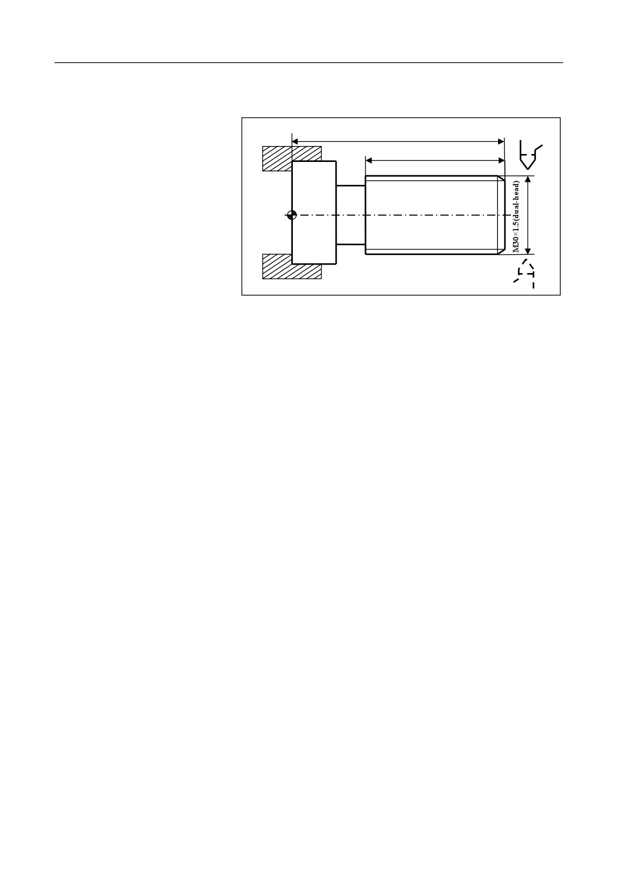
Conduct machining for the workpiece shown in the figure below with
G82 programming. The blank shape has been worded.
100
80
%3324
N1 G54 G00 X35 Z104; Select coordinate system G54, to the cycle start
point
N2 M03 S300; Rotate spindle in the CW direction at 300 r/min
N3 G82 X29.2 Z18.5 C2 P180 F3; The first cycle thread cutting with
depth 0.8 mm
N4 X28.6 Z18.5 C2 P180 F3; The second cycle thread cutting, with
depth 0.4 mm
N5 X28.2 Z18.5 C2 P180 F3; The third cycle thread cutting with depth
0.4 mm
N6 X28.04 Z18.5 C2 P180 F3; The forth cycle thread cutting with depth
0.16 mm
N7 M30; Stop spindle, end the main program, and reset
250
12. Fixed Cycle
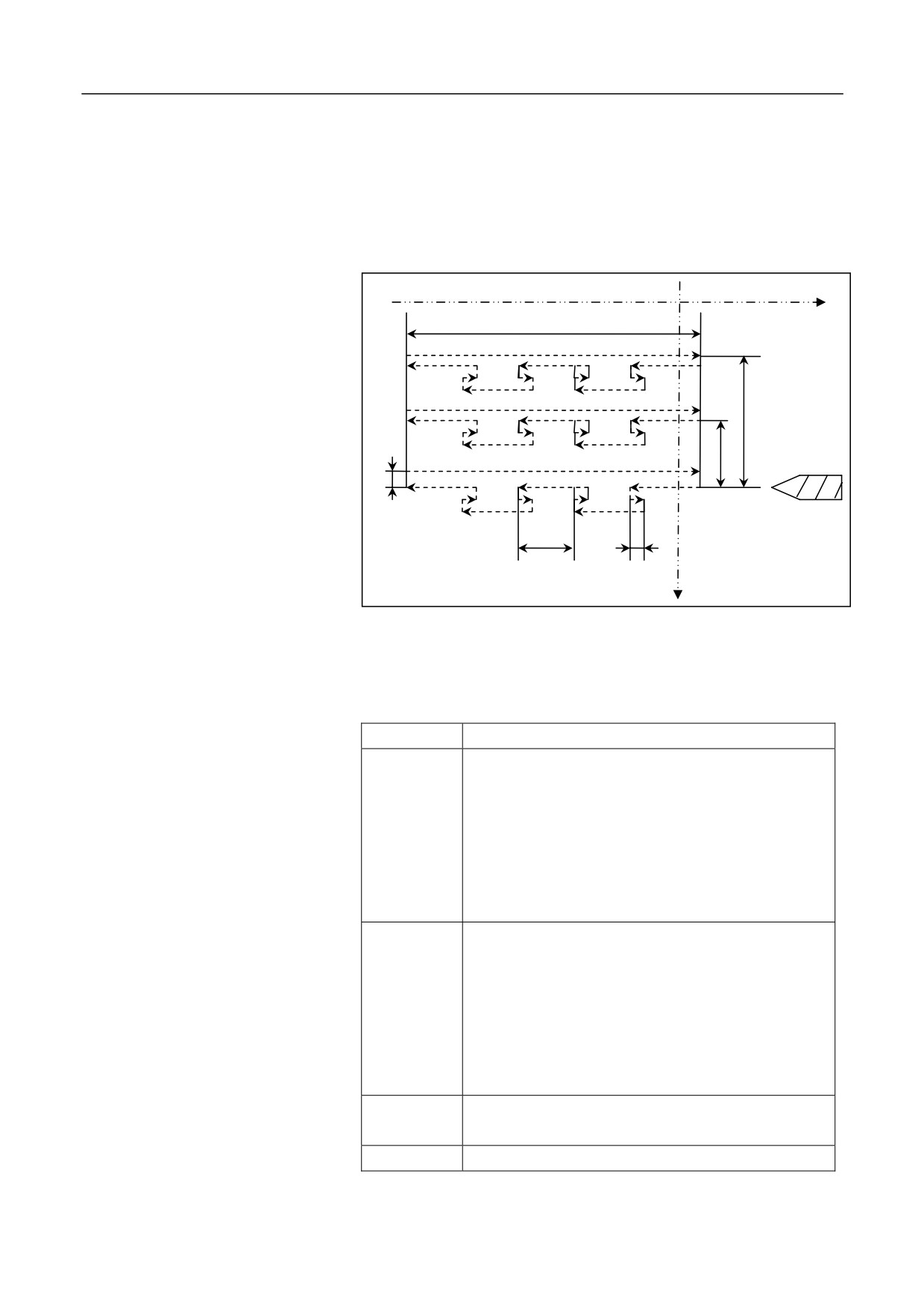
12.2.4 End-Face Deep-Hole Drilling Cycle (G74)
This cycle is used to conduct end-face deep-hole drilling. See the figure
below:
W
Z
U
i
p
ΔK
e
X
Format
G74 X_/U_Z_/W_ Q(ΔK)_R(e)_ I(i)_P(p)_
Parameter
Description
X/U
For the absolute value programming, this value is the
coordinates of the end point at the hole bottom along
the X axis in the workpiece coordinate system; for the
incremental value programming this value is the
relative distance from the end point at the hole bottom
to the start point of the cycle. Use U to express it in
the blueprint. This value is optional.
Z/W
For the absolute value programming, this value is the
coordinates of the end point at the hole bottom along
the Z axis in the workpiece coordinate system; for the
incremental value programming this value is the
relative distance from the end point at the hole bottom
to the start point of the cycle. Use W to express it in
the blueprint.
R
The retract amount along the Z axis. This value must
be a positive value, and is optional.
Q
The feed depth which must be positive.
251
12. Fixed Cycle
I
The feed width for wide-hole drilling. This value must be a
positive value, and is optional.
P
The retract amount along the X axis. When I is specified, P
must be a positive value. When I is not specified, P may be a
positive or a negative value. This parameter is optional.
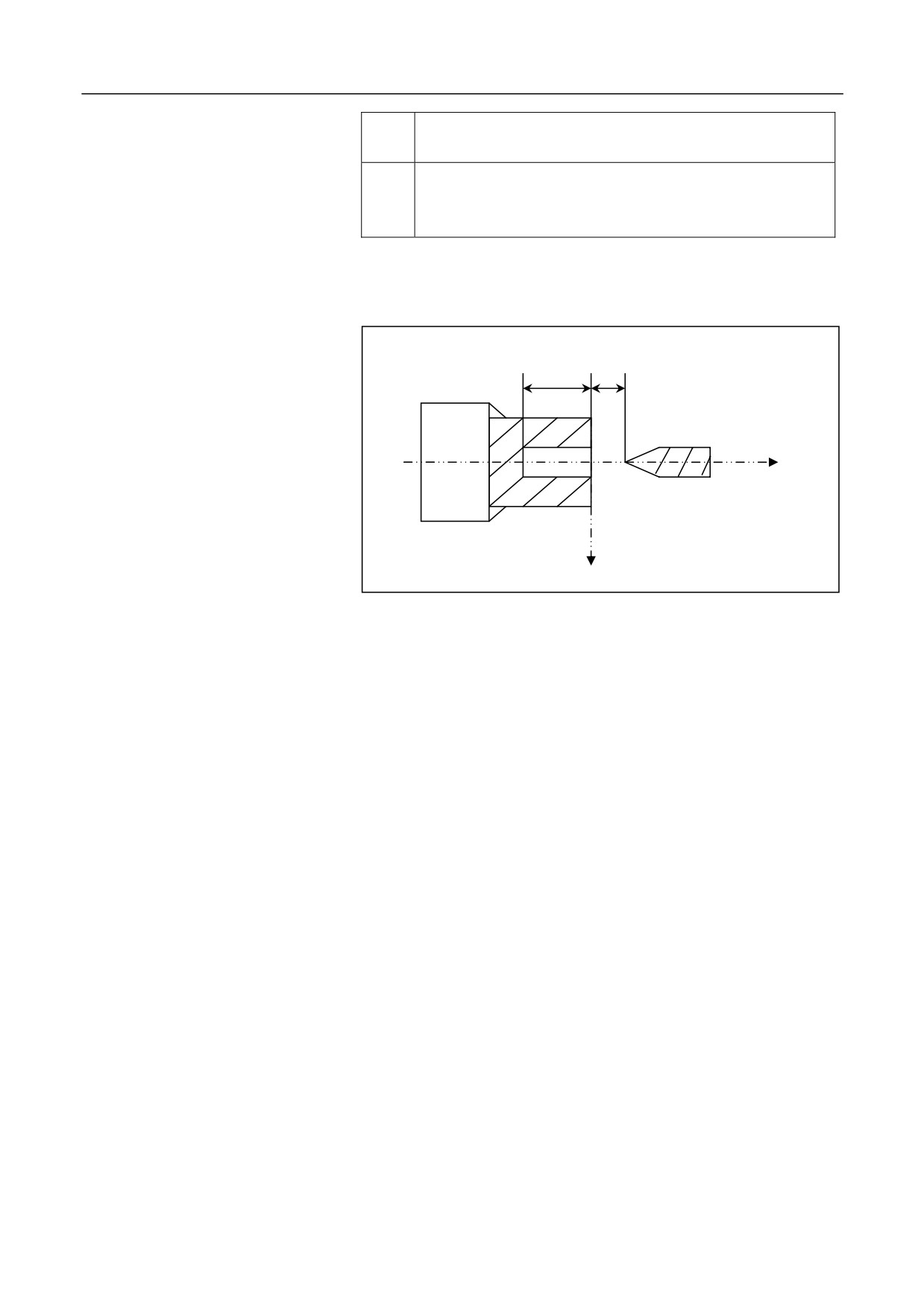
Conduct end-face deep hole drilling cycle with G74.
Example
60
10
Z
X
%1234
T0101
M03S500
G01 X0 Z10F2000
G74 X-10Z-60R1Q5I3P1
M30
252
12. Fixed Cycle
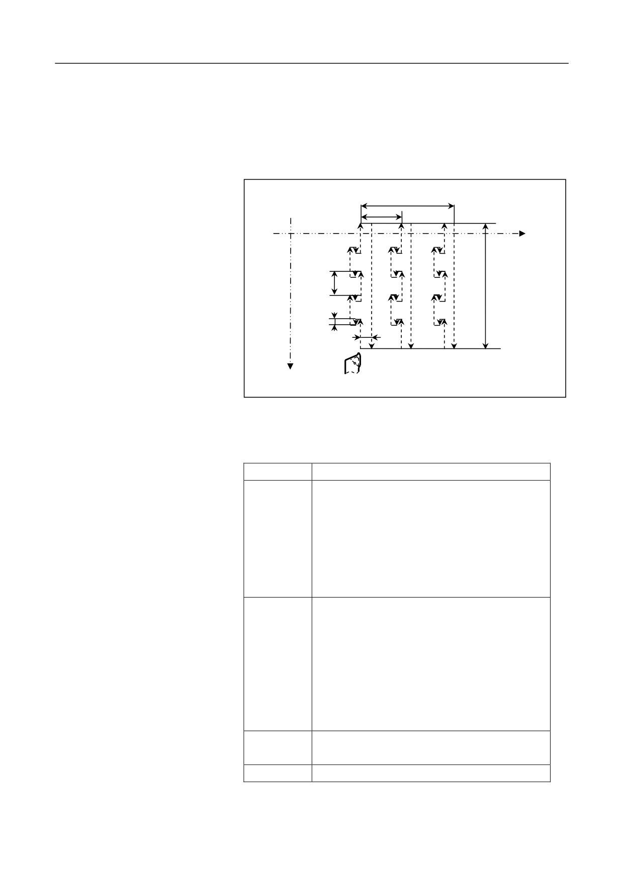
12.2.5 Outer Diameter Grooving Cycle (G75)
This cycle is used to conduct grooving for the outer diameter of the
workpiece. See the figure below:
W
i
Z
ΔK
U/2
e
p
X
Format
G75X_/U_Z_/W_ Q(ΔK)_R(e)_ I(i)_P(p)_
Parameter
Description
X/U
For the absolute value programming, this value is
the coordinates of the end point at the hole bottom
along the X axis in the workpiece coordinate
system; for the incremental value programming
this value is the relative distance from the end
point at the hole bottom to the start point of the
cycle. Use U to express it in the blueprint.
Z/W
For the absolute value programming, this value is
the coordinates of the end point at the hole bottom
along the Z axis in the workpiece coordinate
system; for the incremental value programming
this value is the relative distance from the end
point at the hole bottom to the start point of the
cycle. Use W to express it in the blueprint. This
value is optional.
R
The retract amount along the X axis. This value
must be a positive value, and is optional.
Q
The feed depth which must be positive.
253
12. Fixed Cycle
I
The groove width. This value must be a positive value, and is
optional.
P
The retract amount along the Z axis. When I is specified, P
must be a positive value. When I is not specified, P may be a
positive or negative value. It is optional.
Example
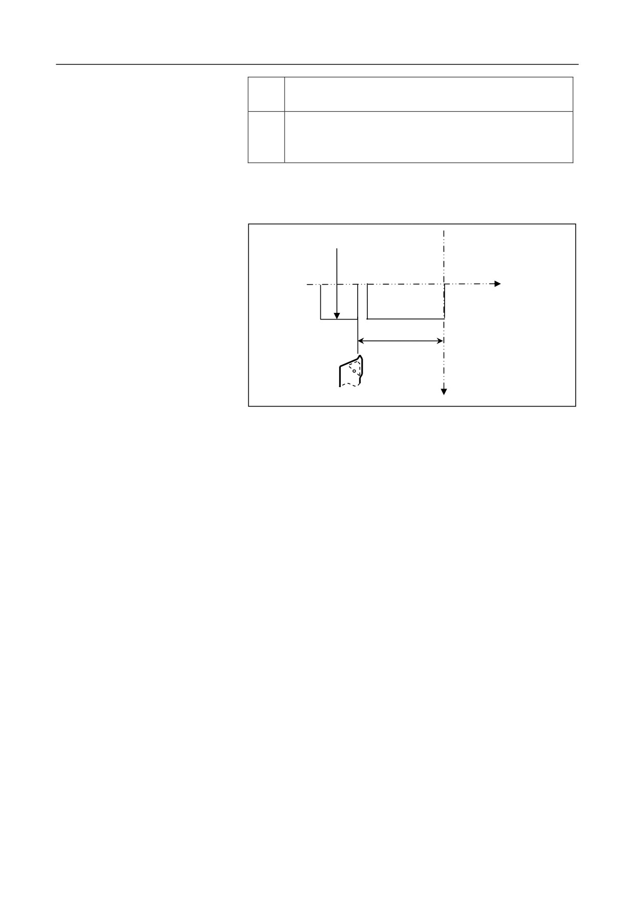
Conduct outer diameter grooving cycle with G75.
ĭ80
Z
50
X
%1234
T0101
M03S500
G01 X50 Z50F2000
G75 X10Z60R1Q5I3P2
M30
254

12. Fixed Cycle
12.3 Fixed Cycle for Drilling of Turning Machines (T)
Commands of fixed cycle for
G Code
Description
drilling of turning machines
G83
Axial drilling cycle
G87
Radial drilling cycle
G84
Axial rigid tapping cycle
G88
Radial rigid tapping cycle
Attention
The commands in this section have no positioning function. To conduct
positioning, you need to specify G01 or G00 outside the fixed cycle.
255
12. Fixed Cycle
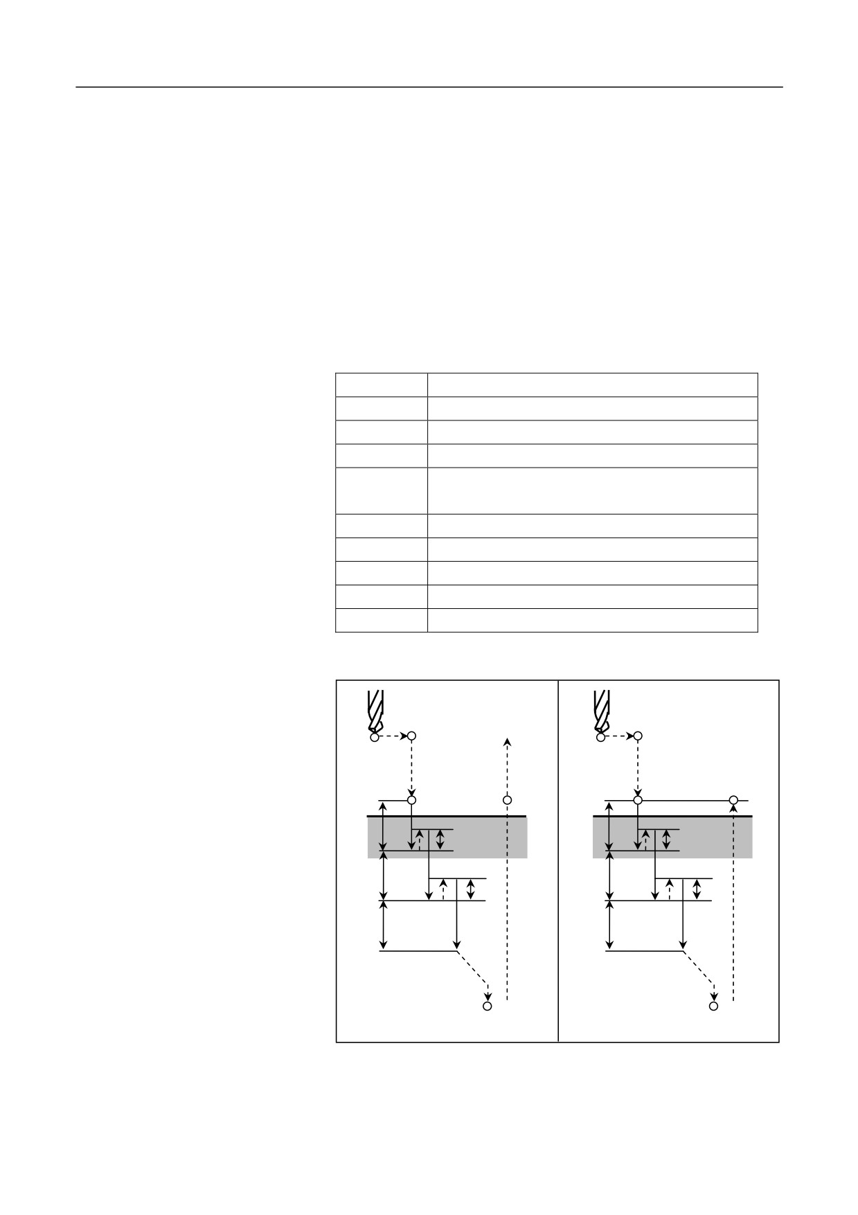
12.3.1 Axial Drilling Cycle (G83)/Radial Drilling Cycle (G87)
This cycle is used for the high-speed deep-hole drilling, with the cutting
feed speed for drilling, specified distance for tool exit, and periodically
repeat until the hole bottom. The chips is discharged out of the hole
during tool exit.
Format
G87X(U)_R_Q_K_P_F_H_
Parameter
Description
X/Z
Hole bottom coordinates.
R
The distance from the initial plane to the R plane.
Q
The cutting depth for each time.
P
The duration when the tool remains at the hole
bottom.
F
Feed speed.
K
Tool exit distance.
H1
Exit with the specified distance K.
H2
Exit to the R point.
H3
Directly drilling to the hole bottom.
• H1 Mode
MĮ
Initial plane
MĮ
M (Į+1), P2
M (Į+1)
Point R
Point R
Point R
P2
q
q
d
d
q
q
d
d
q
q
P1
Point Z
P1
Point Z
G83 or G87 (G98)
G83 or G87 (G99)
256
12. Fixed Cycle
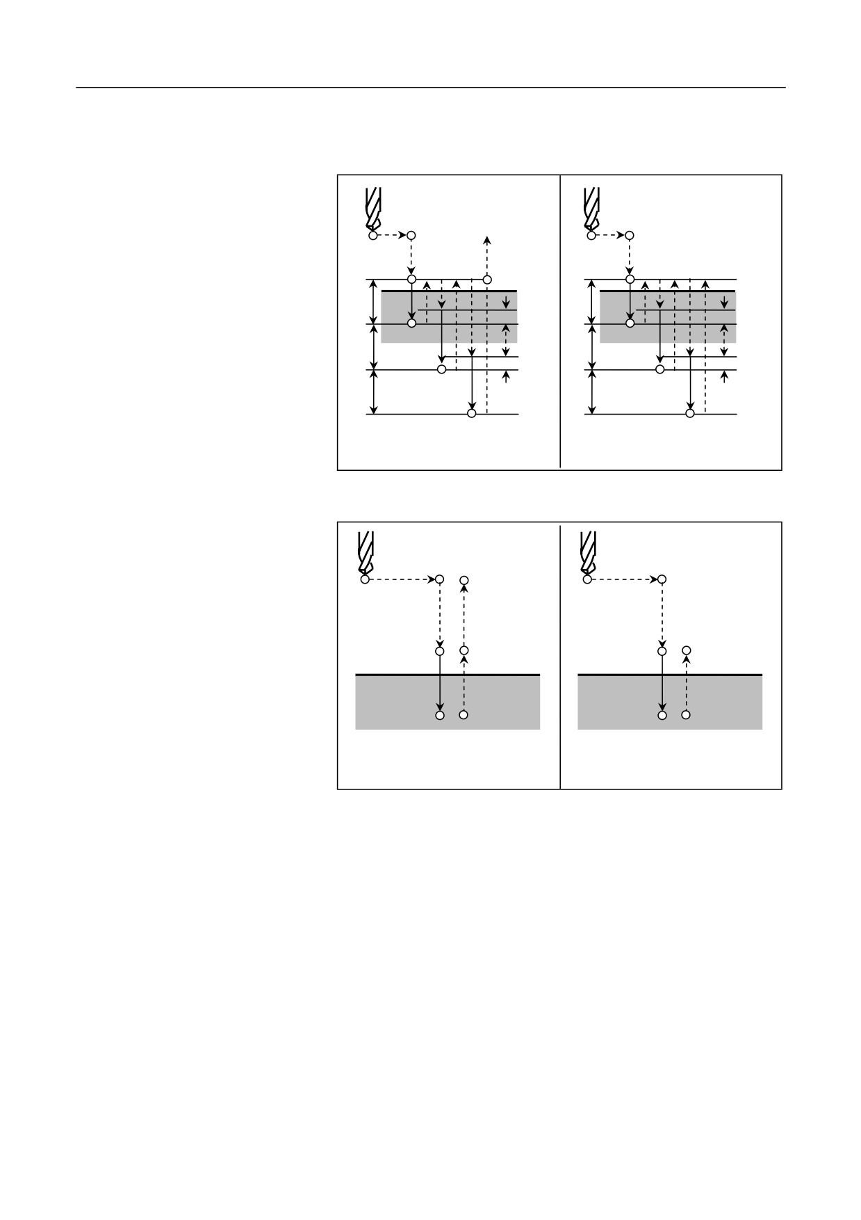
• G83Z(W)_R_Q_K_P_F_H_
• H2 mode
MĮ
Initial plane
MĮ
M (Į+1)
M (Į+1), P2
Point R
Point R
P2
q
q
d
d
q
q
d
d
q
q
Point Z
Point Z
P1
P1
G83 or G87 (G98)
G83 or G87 (G99)
• H3 mode
MĮ
Initial plane
MĮ
R plane
R plane
M (Į+1), P2
M (Į+1), P2
Point Z
Point Z
P1
P1
G83 or G87 (G98)
G83 or G87 (G99)
257
12. Fixed Cycle
Example
%1111
g54x0z50
g98g83z-10r10q5k2p1000f200h1
g99g83z-10r10q5k2p1000f200h1
g0x0z50
g98g83z-10r10q5k2p1000f200h2
g99g83z-10r10q5k2p1000f200h2
g0x0z50
g98g83z-10r10q5k2p1000f200h3
g99g83z-10r10q5k2p1000f200h3
m30
%1111
g54z0x50
g98g87x-10r10q5k2p1000f200h1
g99g87x-10r10q5k2p1000f200h1
g0z0x50
g98g87x-10r10q5k2p1000f200h2
g99g87x-10r10q5k2p1000f200h2
g0z0x50
g98g87x-10r10q5k2p1000f200h3
g99g87x-10r10q5k2p1000f200h3
m30
Attention
When H=1, the tool exits with the distance specified by K. When the
tapping is in the H1 and H2 mode, the cutting depth Q and retract
amount K must be specified.
258
12. Fixed Cycle
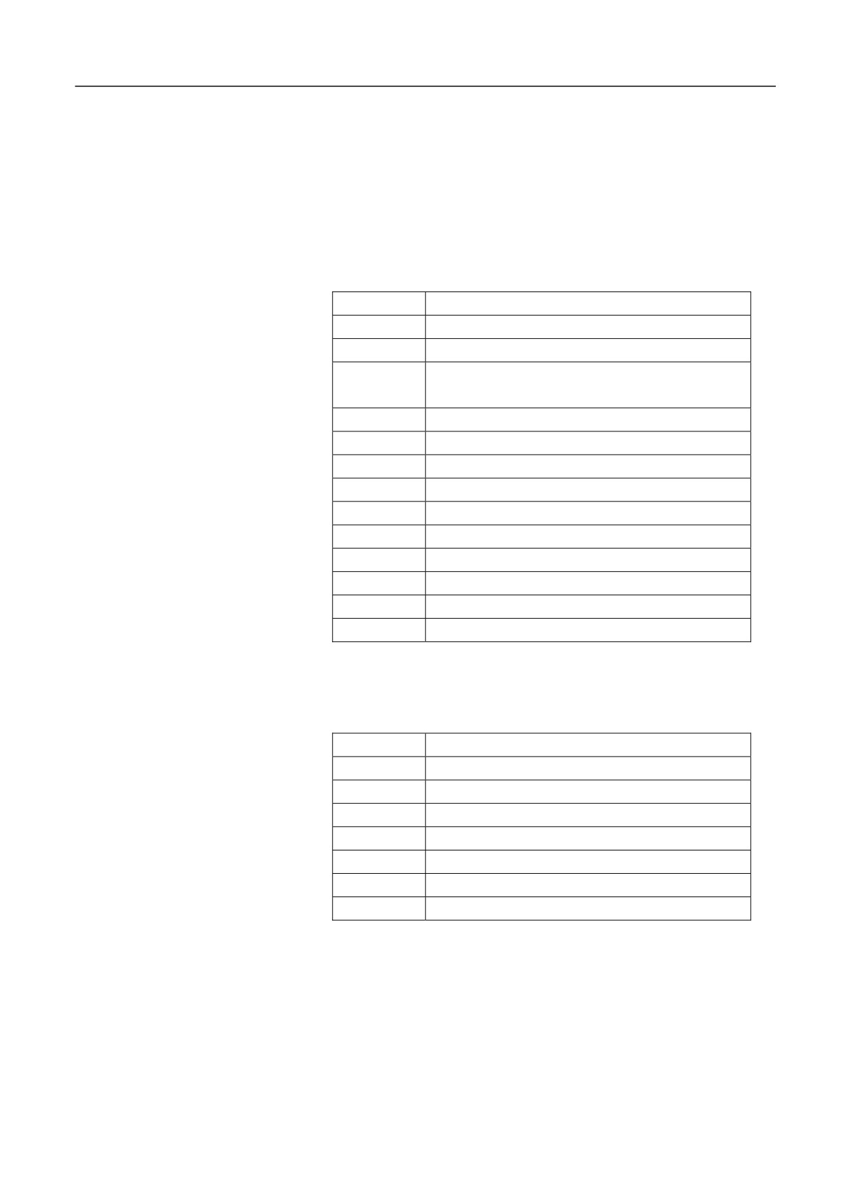
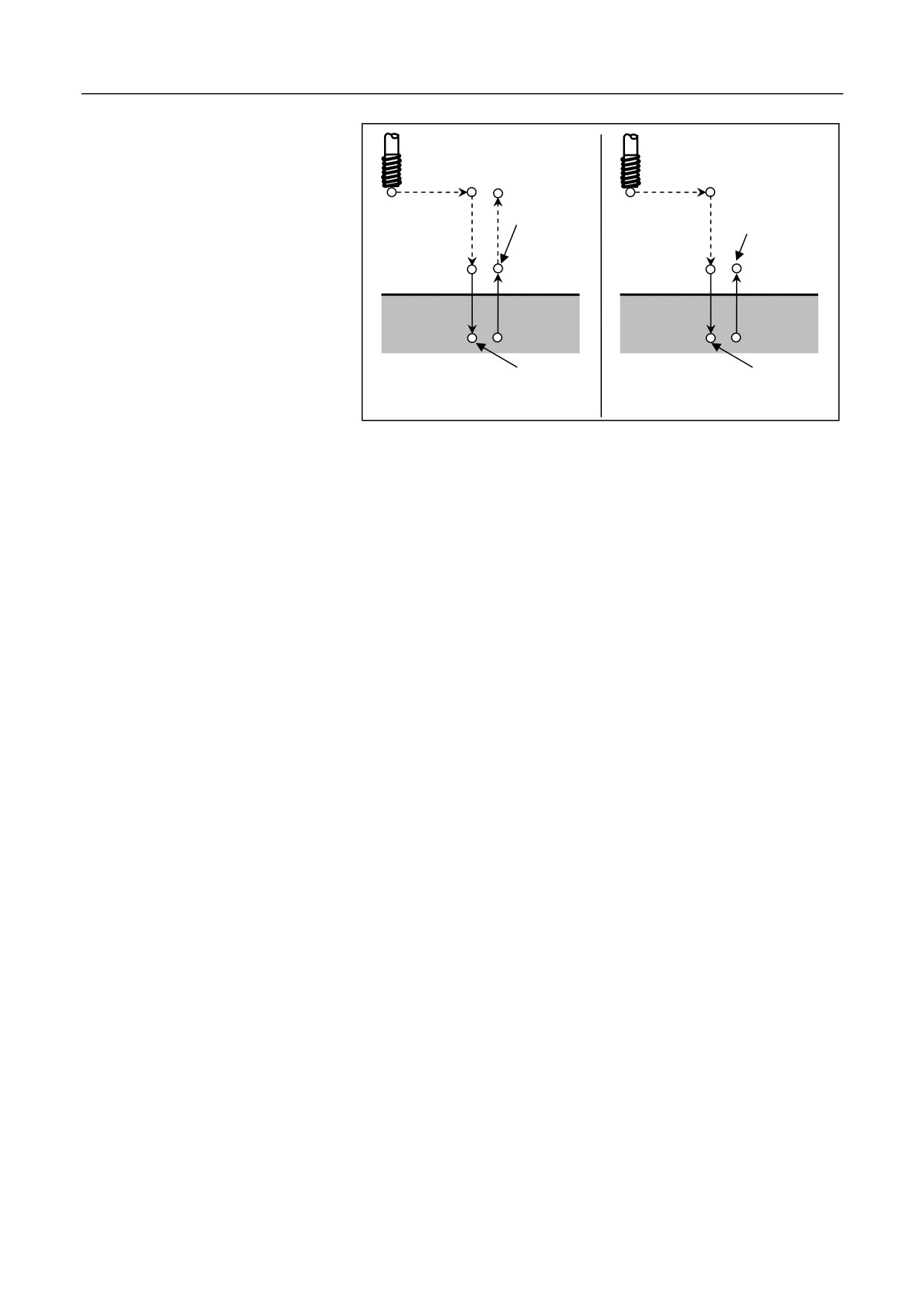
12.3.2 Axial Rigid Tapping Cycle (G84)/Radial Rigid Tapping Cycle (G88)
This cycle is used for tapping. In this cycle, the spindle rotates in the
counter clockwise direction when it reaches the hole bottom.
Format 1
G84 Z(W)_R_P_Q_E_J_K_F_H_
Parameter
Description
Z
Hole bottom coordinates.
R
The distance from the initial plane to the R plane.
P
The duration when the tool remains at the hole
bottom.
F
Feed speed.
Q
Cutting depth.
K
Retract amount
E1
Clockwise tapping.
E2
Counter clockwise tapping
J1
Tapping with the first spindle C.
J2
Tapping with the second spindle A.
H1
Exit with the distance specified by K.
H2
Back to the point R.
H3
Directly back to the hole bottom.
Format 2
G88X(U)_R_E_Q_K_H_P_F_(Tapping with the second spindle A only)
Parameter
Description
E1
Clockwise tapping.
E2
Counter clockwise tapping
Q
Cutting depth.
K
Retract amount
H1
Exit with the distance specified by K.
H2
Back to the point R.
H3
Directly back to the hole bottom.
259
12. Fixed Cycle
Initial plane
Spindle CW
MĮ
MĮ
rotation
Spindle CW
rotation
Plane of point
Point R
Point R
R
P1
Point Z
P1
Point Z
Spindle CCW rotation
Spindle CCW rotation
G84 or G88 (G98)
G84 or G88 (G99)
Example
M3 S1=1000; Rotate No. 1 spindle
G0X50Z50
M5
G84Z-10R20P1000F1000H1
M33 S2=1000; Rotate No. 2 spindle
G4P1000
M55
G84Z-10R20P1000F1H2
G88X-10R20P1000F1
M30
260
12. Fixed Cycle
12.4 Compound Cycle for Turning Machines (T)
This fixed cycle simplifies programming by using the finishing shape
data to describe the roughing tool path. This system provides four
combined cycle:
G71: Inner (outer) diameter roughing compound cycle
G72: End-face roughing compound cycle
G73: Closed cutting compound cycle
G76: Thread cutting compound cycle
Through this instruction, you need to specify only the finishing path and
roughing cutting depth, the system will automatically calculate the
roughing path and the cutting count.
Attention
This cycle is used only for turning machines.
For G71, G72, and G73 compound cycle, pay attention to the following
items:
1. The program block specified by P should have the commands of
G00 or G01in group 01; otherwise, an alarm will be reported.
2. In the MDI mode, the compound cycle command cannot be
executed.
3. In the compound cycle G71, G72 and G73, the blocks of which
sequence number is specified by P or Q should not have M98
subprogram calling or M99 subprogram returning command.
4. In the compound cycle G71, G72 and G73, tool compensation
cannot be executed for the blocks of which which sequence number
is specified by P or Q.
261
12. Fixed Cycle
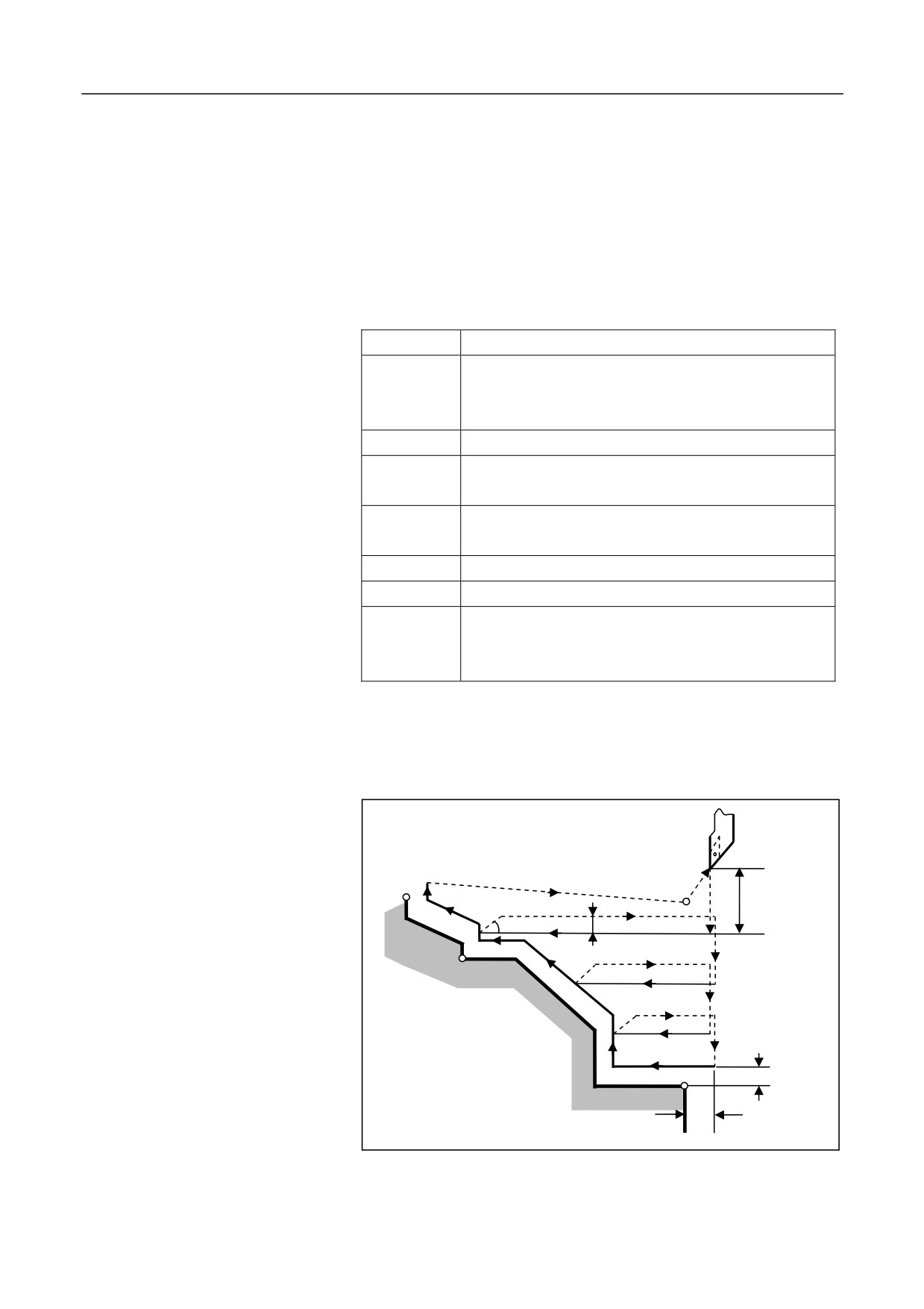
12.4.1 Inner (Outer) Diameter Roughing Compound Cycle (G71)
This cycle can be divided into inner (outer) diameter roughing compound
cycle with groove and without groove.
Inner
(outer) diameter roughing
G71 U(Δd) R(r) P(ns) Q(nf) X(Δx) Z(Δz) F(f) S(s) T(t);
compound cycle without groove
Parameter
Description
U
Cutting depth
(each cutting amount). The symbol
("+/"-") is not specified with the value. The direction
is determined by the vector AA'.
R
Each retract amount.
P
The first program block sequence number for finish
machining (AA' in the figure below).
Q
The last program block sequence number for finish
machining (B'B in the figure below).
X
Finishing allowance in the X axis direction.
Z
Finishing allowance in the Z axis direction.
F S T
During roughing, the F, Sand T in G71 are valid, while
in finishing, the F, S and T between the ns program
block and nf program block are valid.
Description
This cycle is used for the roughing as shown in the figure below, and the
tool returns to the cycle start point. The finishing path AĺA'ĺB'ĺB is
executed based on the command order.
A
B
Δd
45 degrees
r
B’
Δx/2
A’
Δz
262
12. Fixed Cycle
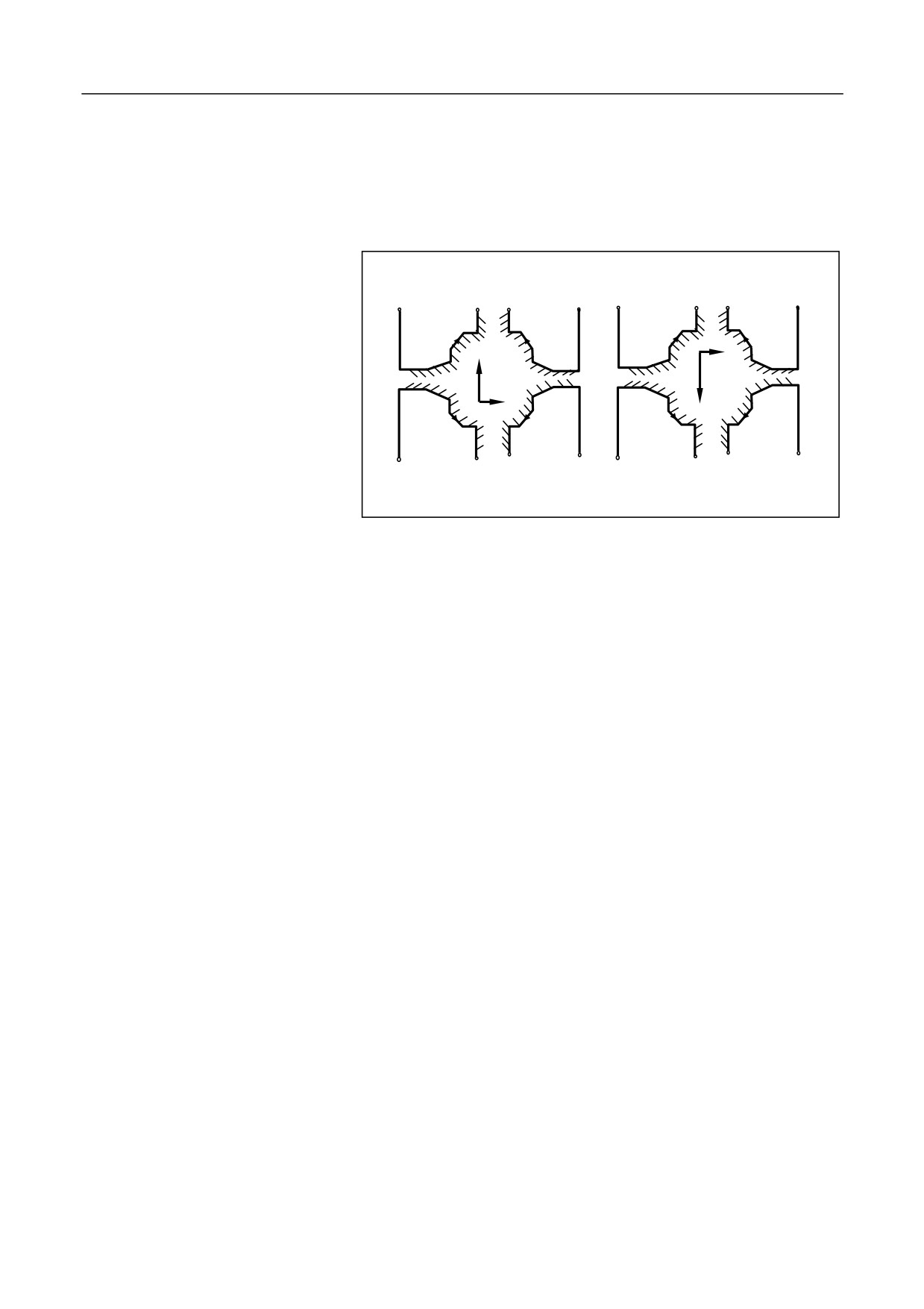
XZ symbol ("+"/"-")
In the cutting cycle G71, the cutting feed direction is parallel to the Z
axis. The symbol of X (ΔU) and Z (ΔW) is as shown below, where "+"
indicates a positive direction along the axis, "-" indicates the negative
direction along the axis.
B B
B B
A
A
A
A
X(+) Z(-)
X(+) Z(+)
X(-) Z(-)
X(-)Z(+)
Aƍ
Aƍ
A
Aƍ
Aƍ
Aƍ
A
Aƍ
X(-) Z(-)
X(-)Z(+)
X(+) Z(-)
X(+)
A
B
B
A
A
B
B
A
Attention
1.
In the last program block of the finishing path with Q, there must be
X axial movements.
2.
In outer diameter roughing compound cycle G71, the cycle start
point must be the highest point, and in the inner diameter of the
roughing compound cycle , it must be the lowest point.
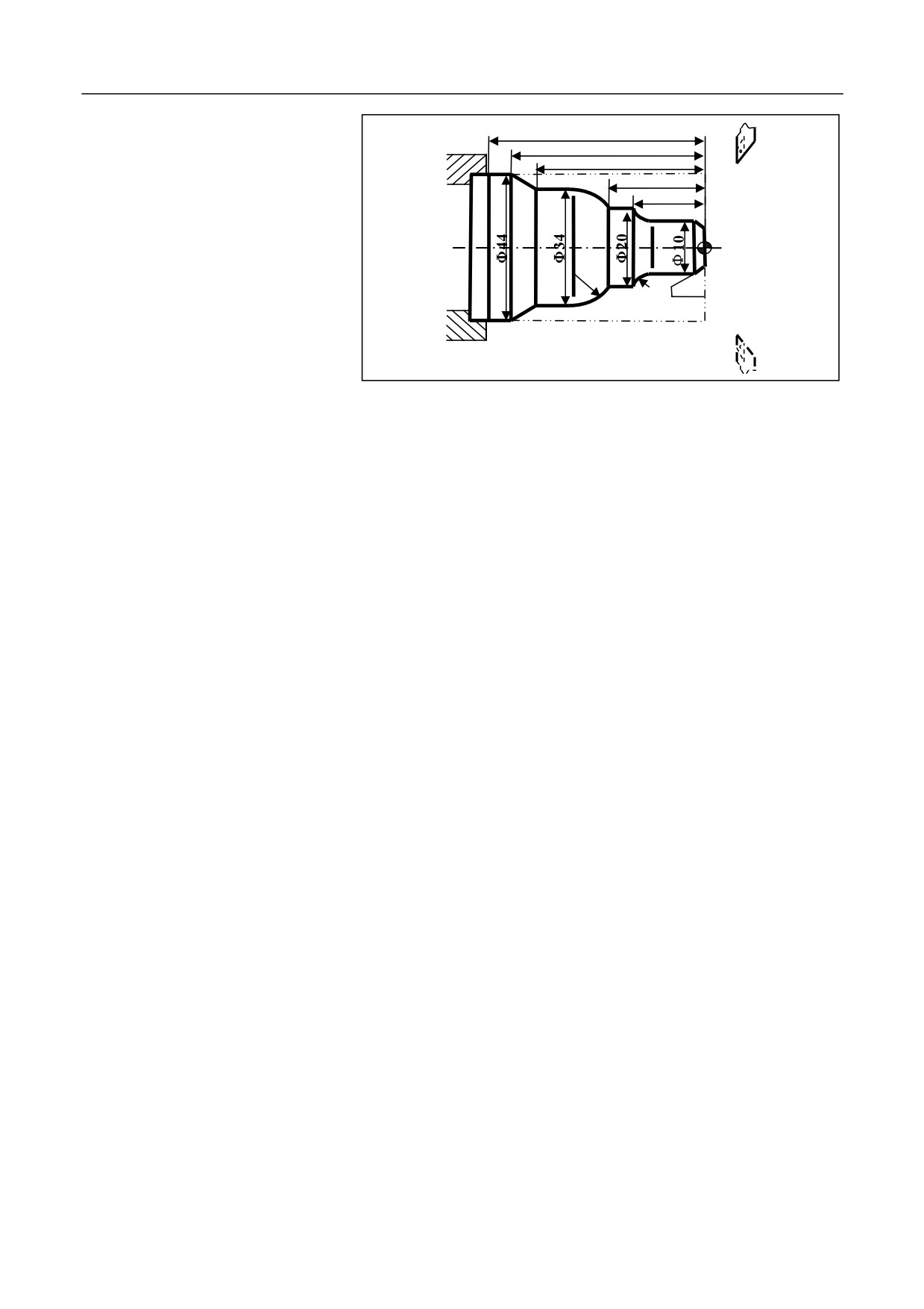
Example 1
Use outer diameter roughing compound cycle to create a machining
program for the workpiece shown as below: cycle start point: A (46, 3);
cutting depth
1.5 mm
(radius); retract amount:
1 mm; finishing
allowance along the X axis: 0.4 mm; finishing allowance along the Z
axis: 0.1 mm. The dotted lines indicate the workpiece.
263
12. Fixed Cycle
82
62
52
35
25
R7
R5 2×45°
%3325
T0101; Define coordinate system, and select No. 1 tool.
N1 G00 X80 Z80; Go to the program start point
N2 M03 S400; Spindle rotates at 400r/min
N3 G01 X46 Z3 F100; The tool goes to the cycle start point.
N4 G71U1.5R1P5Q14X0.4 Z0.1; Roughing amount: 1.5 mm; finishing
amount: X0.4 mm, Z0.1 mm
N5 G00 X0; Start finishing contour , go to the extended line of chamfer
N6 G01 X10 Z-2; Conduct finishing for chamfer of 2×45 degrees
N7 Z-20; Conduct finishing for ĭ10 outer circle
N8 G02 U10 W-5 R5; Conduct finishing for R5 arc
N9 G01 W-10; Conduct finishing for ĭ20 outer circle
N10 G03 U14 W-7 R7; Conduct finishing for R7 arc
N11 G01 Z-52; Conduct finishing for ĭ34 outer circle
N12 U10 W-10; Conduct finishing for outer cone
N13 W-20; Conduct finishing for ĭ44 outer circle
N14 U1; End finishing
N15 X50; Exit the machined face
N16G00 X80 Z80; Back to the tool exchange position
N17 M05; Stop spindle
264
12. Fixed Cycle
N18 M30 ; End the main program and reset
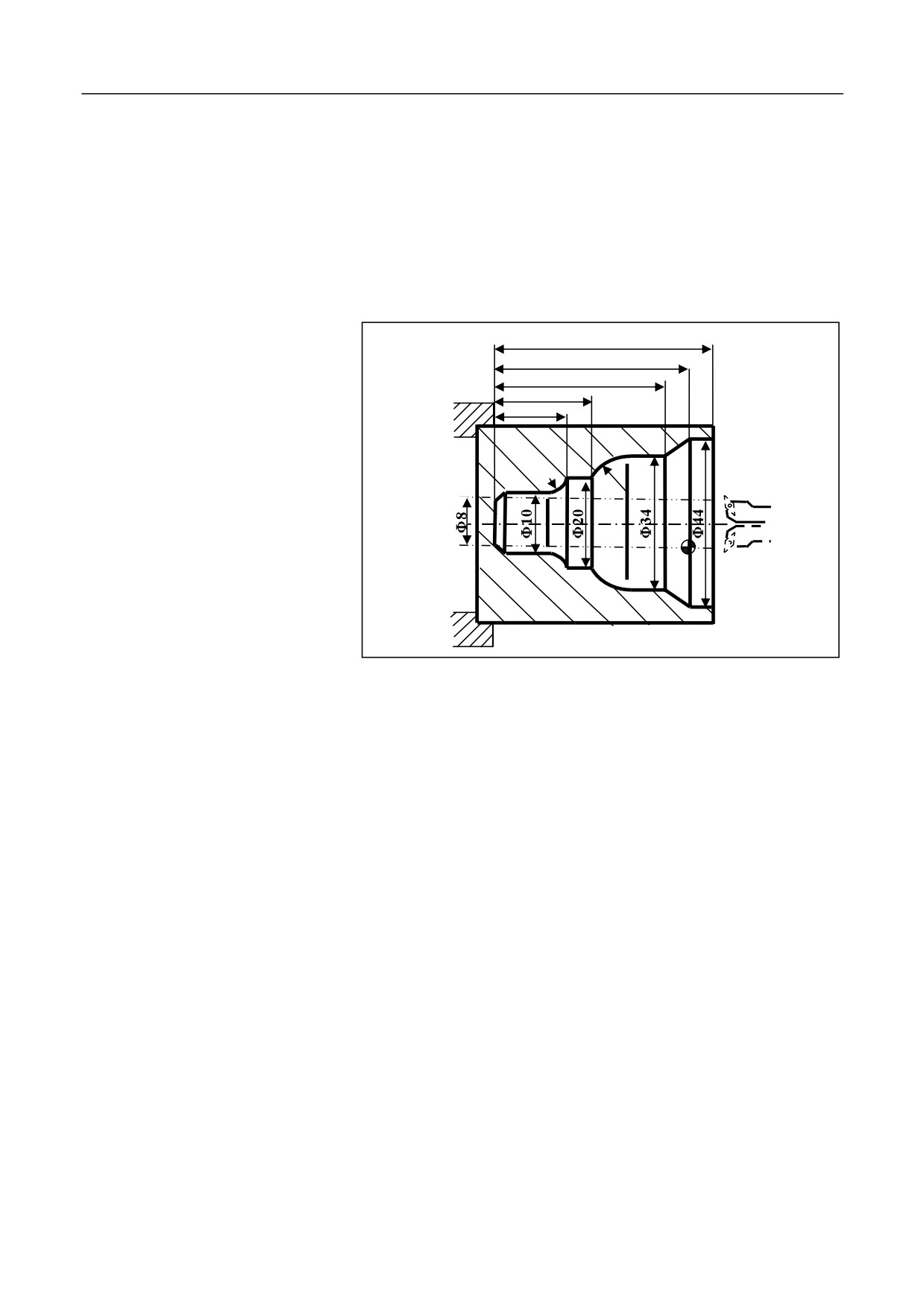
Example 2
Use inner diameter roughing compound cycle to create a machining
program for the workpiece shown as below: cycle start point: A (6, 5);
cutting depth:
1.5 mm
(radius); retract amount:
1 mm; finishing
allowance along the X axis: 0.4 mm; finishing allowance along the Z
axis: 0.1mm. The dotted lines indicate the workpiece.
82
62
52
35
25
R5
R7
2×45°
%3326
N1 T0101; Select No.1 tool, and define the coordinate system
N2 G00 X80 Z80; Go to the program start point or tool exchange
position.
N3 M03 S400; Rotate Spindle in the clockwise direction at 400r/min
N4 X6 Z5; Go to the cycle start point
G71U1R1P8Q16X-0.4Z0.1 F100; Start roughing
N5 G00 X80 Z80; After roughing, go to the tool exchange position
N6 T0202; Change to No.2 tool, and define the coordinate system
N7 G00 G41X6 Z5; Add tool nose arc radius compensation to No.2 tool
N8 G00 X44; Start finishing , go to the outer circle of ĭ44
N9 G01 Z-20 F80; Conduct finishing for the outer circle of ĭ44
N10 U-10 W-10; Conduct finishing for the outer cone
265

12. Fixed Cycle
N11 W-10; Conduct finishing for the outer circle of ĭ34
N12 G03 U-14 W-7 R7; Conduct finishing for the arc of R7
N13 G01 W-10; Conduct finishing for the outer circle of ĭ20
N14 G02 U-10 W-5 R5; Conduct finishing for the arc of R5
N15 G01 Z-80 ; Conduct finishing for the outer circle of ĭ10
N16 U-4 W-2; Conduct finishing for
2×45° chamfer, and end the
finishing
N17 G40 X4; Exit the machined face, and cancel the tool arc radius
compensation
N18 G00 Z80; Exit the inner hole of the workpiece
N19 X80; Return to the program start point or the tool exchange position
N20 M30; Stop spindle, end the main program, and reset
Inner
(outer) diameter roughing
G71 U(Δd) R(r) P(ns) Q(nf) E(e) F(f) S(s) T(t);
compound cycle with groove
Parameter
Description
Format
U
Cutting depth
(each cutting amount). The symbol
("+"/"-") is not specified with the value. The direction
is determined by the vector AA'.
R
Each retract amount.
P
The first program block sequence number for
finishing path (AA' in the figure below).
Q
The last program block sequence number for finishing
path (B'B in the figure below).
E
The finishing allowance, which indicates the distance
along the X axis; It is positive for outer diameter
cutting and negative for inner diameter cutting.
F S T
During roughing, the F, S, and T in G71 are valid,
while in finishing, the F, S, and T between the ns
program block and nf program block are valid.
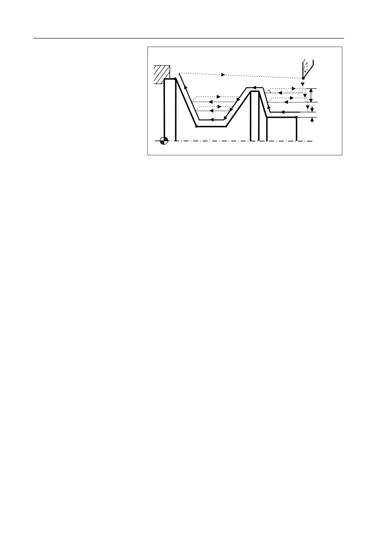
Description
This cycle is used for the roughing as shown in the figure below. The
finishing path is AĺA'ĺB'ĺB.
266
12. Fixed Cycle
B
A
45°
r
Δd
e
A'
B'
Attention
1.
G71 must have ns and nf of P/Q, which should correspond to the
start and end number of the finishing path; otherwise, the cycle
cannot be executed.
2.
The program block of ns must be G00/G01. In other words, the
action from A to A' must be a straight line or point positioning
movement.
3.
In the program blocks from ns to nf, no subprogram (4.03) should
be included.
267
12. Fixed Cycle
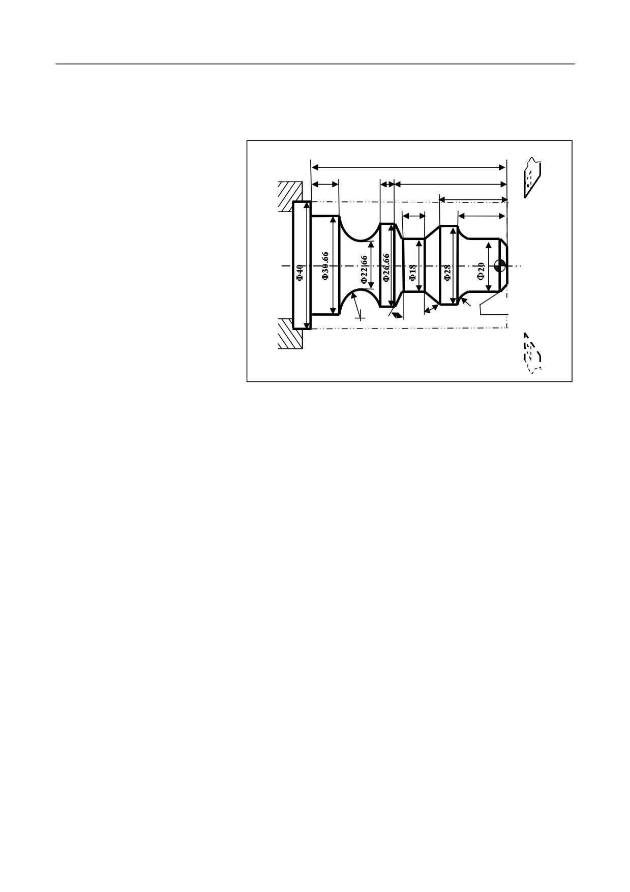
Example
Use outer diameter roughing compound cycle with groove to create a
machining program for the workpiece shown as below: the dotted lines
indicate the workpiece.
61.5
10
5
32.5
17
(8)
12
R4
R10
2×45 degrees
degrees
30 degrees
%3327
N1 T0101; Select No. 1 tool and define coordinate system
N2 G00 X80 Z100; Go to the program start point or tool exchange
position
M03 S400; Rotate spindle in the clockwise direction at 400 r/min
N3 G00 X42 Z3; The tool goes to the cycle start point.
N4G71U1R1P8Q19E0.3F100; Conduct rough cutting cycle with groove.
N5 G00 X80 Z100; After roughing, go to the tool exchange position
N6 T0202; Select No.2 tool, and define the coordinate system
N7 G00 G42 X42 Z3; Add tool nose arc radius compensation to No.2
tool
N8 G00 X10; Conduct finishing, go to the extended line of chamfer
N9 G01 X20 Z-2 F80; Conduct finishing for 2×45° chamfer
N10 Z-8; Conduct finishing for ĭ20 outer circle
N11 G02 X28 Z-12 R4; Conduct finishing for R4 arc
N12 G01 Z-17; Conduct finishing for ĭ28 outer circle
N13 U-10 W-5; Conduct finishing for under-cut cone
268
12. Fixed Cycle
N14 W-8; Conduct finishing for ĭ18 outer circular groove
N15 U8.66 W-2.5; Conduct finishing for upper-cut cone
N16 Z-37.5; Conduct finishing for ĭ26.66 outer circle
N17 G02 X30.66 W-14 R10; Conduct finishing for R10 under-cut arc
N18 G01 W-10; Conduct finishing for ĭ30.66 outer circle
N19 X40; Exit the machined face, and end the finishing
N20 G00 G40 X80 Z100 ; Cancel the radius compensation, and back to
the tool exchange position
N21 M30; Stop spindle, end the main program, and reset
269
12. Fixed Cycle
12.4.2 End-Face Roughing Compound Cycle (G72)
This cycle is similar as G71. The difference is that the cutting of G72 is
parallel to the X axis.
Foramt
G72 W(ǻd) R(r) P(ns) Q(nf) X(ǻx) Z(ǻz) F(f) S(s) T(t);
Parameter
Description
W
Cutting depth
(each cutting amount). The sign
(positive or negative) is not specified with the value.
The direction is determined by the vector AA'.
R
Each retract amount.
P
The first program block sequence number for
finishing path (AA' in the figure below).
Q
The last program block sequence number for
finishing path (BB' in the figure below).
X
Finishing allowance in the X axis direction.
Z
Finishing allowance in the Z axis direction.
F S T
During roughing, the F, S, and T in G72 are valid,
while in finishing, the F, S, and T between the ns
program block and nf program block are valid.
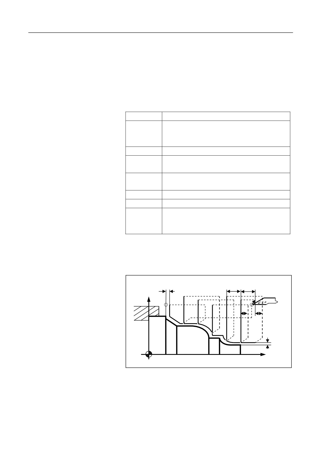
Description
This cycle is used for the roughing and finishing as shown in the figure
below. The finishing path is AĺA'ĺB'ĺB.
Δz
Δd
Δd
+X
A
A'
Δd
r
r
B'
Δx/2
B'
+Z
270
12. Fixed Cycle
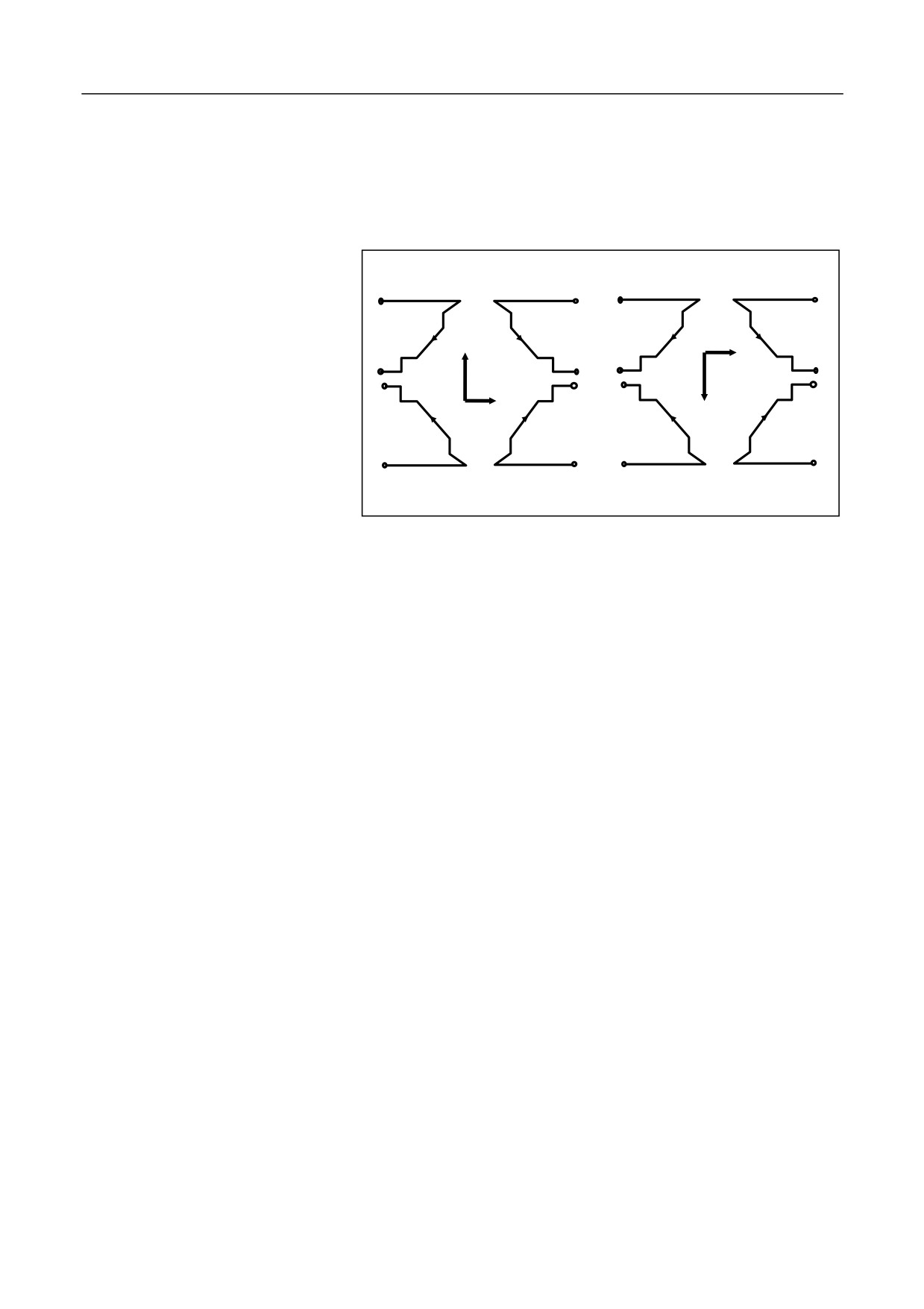
In the cutting cycle of G72, the cutting feed direction is parallel to the X
axis, and the sign of X(ΔU) and Z(ΔW) is shown in the figure below. The
sign "+" indicates the movement along the positive direction of the axis
Symbol of XZ value ("+"/"-")
while "-" indicates the movement along the negative direction of the
axis.
A
A
A
A
A'
A'
A'
A'
X(+) Z(+)
X(-) Z(-)
X(+) Z(-)
X(-) Z(+)
X
Z
B
B
B
B
B
B
B
B
Z
X
X(-) Z(+)
X(+) Z(-)
X(+) Z(+)
X(-) Z(-)
A'
A'
A'
A'
A
A
A
A
Attention
1.
The G72 command should have the address specified by P or Q;
otherwise, this cycle cannot be executed.
2.
The ns program should include G00/G01 coammnds, to execute the
action from A to A'. In addition, this program block should not have
the commands for the movement along the X axis.
3.
The program blocks from ns to nf may include G02/G03 commands,
but cannot include subprograms.
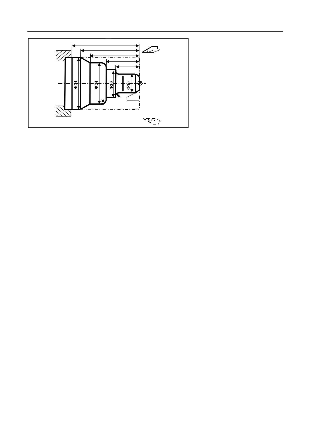
Example 1
Create a machining program for the workpiece shown as below: cycle
start point: A (80, 1); cutting depth 1.2 mm; tool exit quantity: 1 mm;
finishing allowance along the X axis: 0.2 mm; finishing allowance along
the Z axis: 0.5 mm. The dotted lines indicate the workpiece.
271
12. Fixed Cycle
60
50
40
26
15
R4
R2 2×45
degrees
%3328
N1 T0101; Select No. 1 tool and define coordinate system
N2 G00 X80 Z80; Go to the program start point
N3 M03 S400; Rotate spindle in the clockwise direction at 400r/min.
N4 X80 Z1; Go to the cycle start point
N5 G72W1.2R1P8Q17X0.2Z0.5F100; Conduct roughing for the external
end face
N6 G00 X100 Z80; Go to the tool exchange position after roughing.
N7 G42 X80 Z1; Add tool nose arc radius compensation
N8 G00 Z-53; Start finishing , go to the extended line of the cone
N9 G01 X54 Z-40 F80; Conduct finishing for the cone.
N10 Z-30; Conduct finishing for ĭ54 outer circle
N11 G02 U-8 W4 R4; Conduct finishing for R4 arc
N12 G01 X30; Conduct finishing for Z26 end face
N13 Z-15; Conduct finishing for ĭ30 outer circle
N14 U-16; Conduct finishing for Z15 end face
N15 G03 U-4 W2 R2; Conduct finishing for R2 arc
N16 G01 Z-2; Conduct finishing for ĭ10 outer circle
N17 U-6 W3; Conduct finishing for 2×45° chamfer, complete finishing
N18 G00 X50; Exit the machined face
N19 G40 X100 Z80; Cancel the radius compensation and back to the
program start point
N20 M30; Stop spindle, end the main program, and reset
272
12. Fixed Cycle
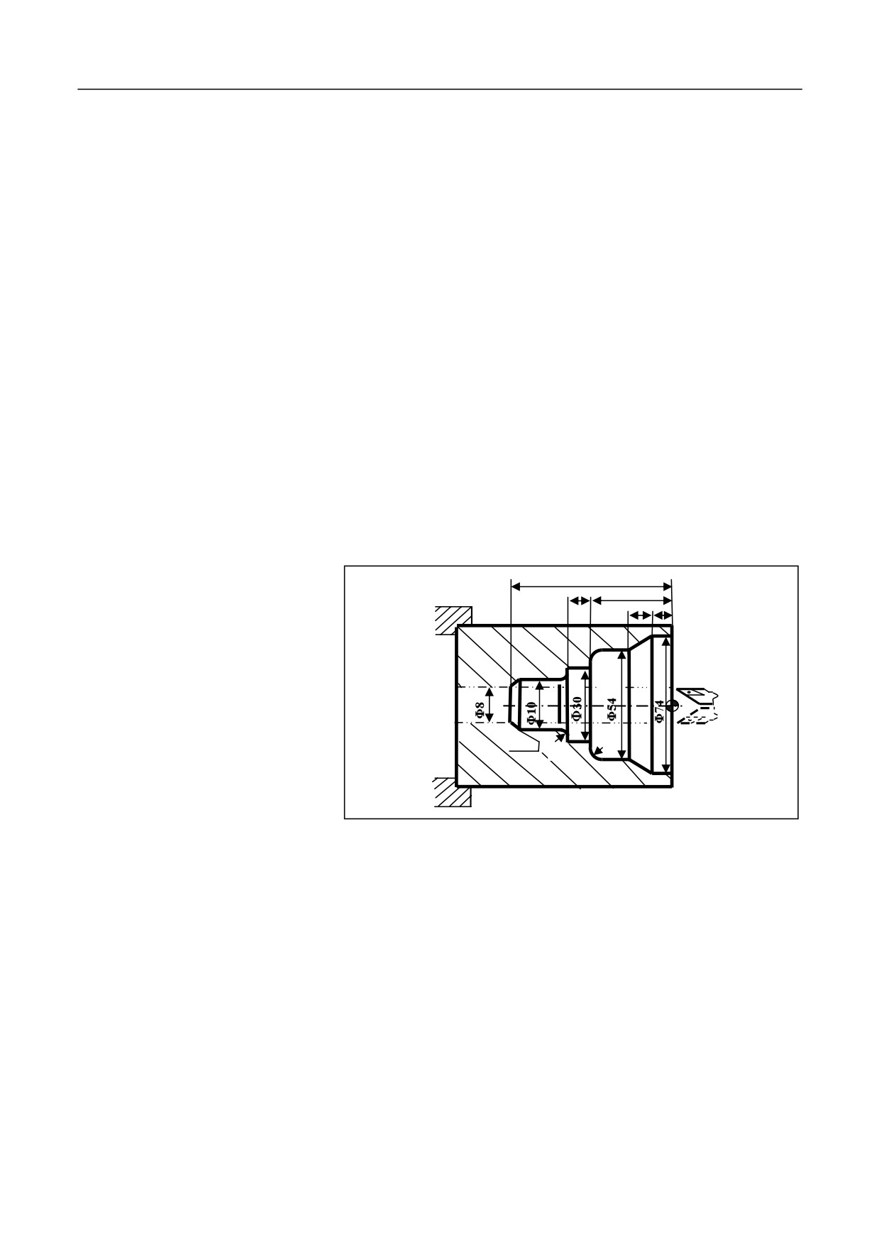
Example 2
Create a machining program for the workpiece shown as below: cycle
start point: A (6, 3); cutting depth: 1.2 mm; tool exit quantity: 1 mm;
finishing allowance along the X axis: 0.2 mm; finishing allowance along
the Z axis: 0.5 mm. The dotted lines indicate the workpiece.
60
11
34
10
10
R4
2×45 degrees
R2
%3329
N1 T0101; Define coordinate system
N2 G00 X100 Z80; Go to the start point
N3 M03 S400; Rotate spindle in the clockwise direction at 400r/min
N4 G00 X6 Z3; Go to the cycle start point
N5 G72W1.2R1P6Q16X-0.2Z0.5F100; Inner end face roughing process
N6 G00 Z-61; Conduct finishing , go to the extended line of chamfer
N7 G01 U6 W3 F80; Conduct finishing for the chamfer 2×45°
N8 W10; Conduct finishing for the outer circle of ĭ10
273
12. Fixed Cycle
N9 G03 U4 W2 R2; Conduct
for the outer circle of ĭ54
finishing for the arc of R2
N15 U20 W10 ; Conduct finishing for the cone
N10 G01 X30; Conduct finishing for
N16 Z3; Conduct finishing for the outer circle of ĭ74, complete
Z45 end face
finishing
N11 Z-34 ; Conduct finishing for the
outer circle of ĭ30
N12 X46; Conduct finishing for Z34
end face
N13 G02 U8 W4 R4; Conduct
N17 G00 X100 Z80; Back to the tool exchange position
finishing for the arc of R4
N18 M30 ; Stop spindle, end the main program, and reset
N14 G01 Z-20 ; Conduct finishing
274
12. Fixed Cycle
12.4.3 Closed Cutting Compound Cycle (G73)
This cycle can be used to cut workpiece with fixed graphics. It can be
used to effectively cut cast molding, forging molding or rough
workpieces.
Without groove
G73 U(ΔI) W(ΔK) R(r) P(ns) Q(nf) X(Δx) Z(Δz) F(f) S(s) T(t)
Parameter
Description
U
Total finishing allowance in the X axis direction.
W
Total finishing allowance in the Z axis direction.
R
Rough cutting count.
P
The first program block sequence number for
finishing path (AA' in the figure below).
Q
The last program block sequence number for finishing
path (BB' in the figure below).
X
Finishing allowance in the X axis direction.
Z
Finishing allowance in the Z axis direction.
F S T
During roughing, the F, S, and T in G73 are valid,
while during finishing, the F, S, and T between the ns
program block and nf program block are valid.
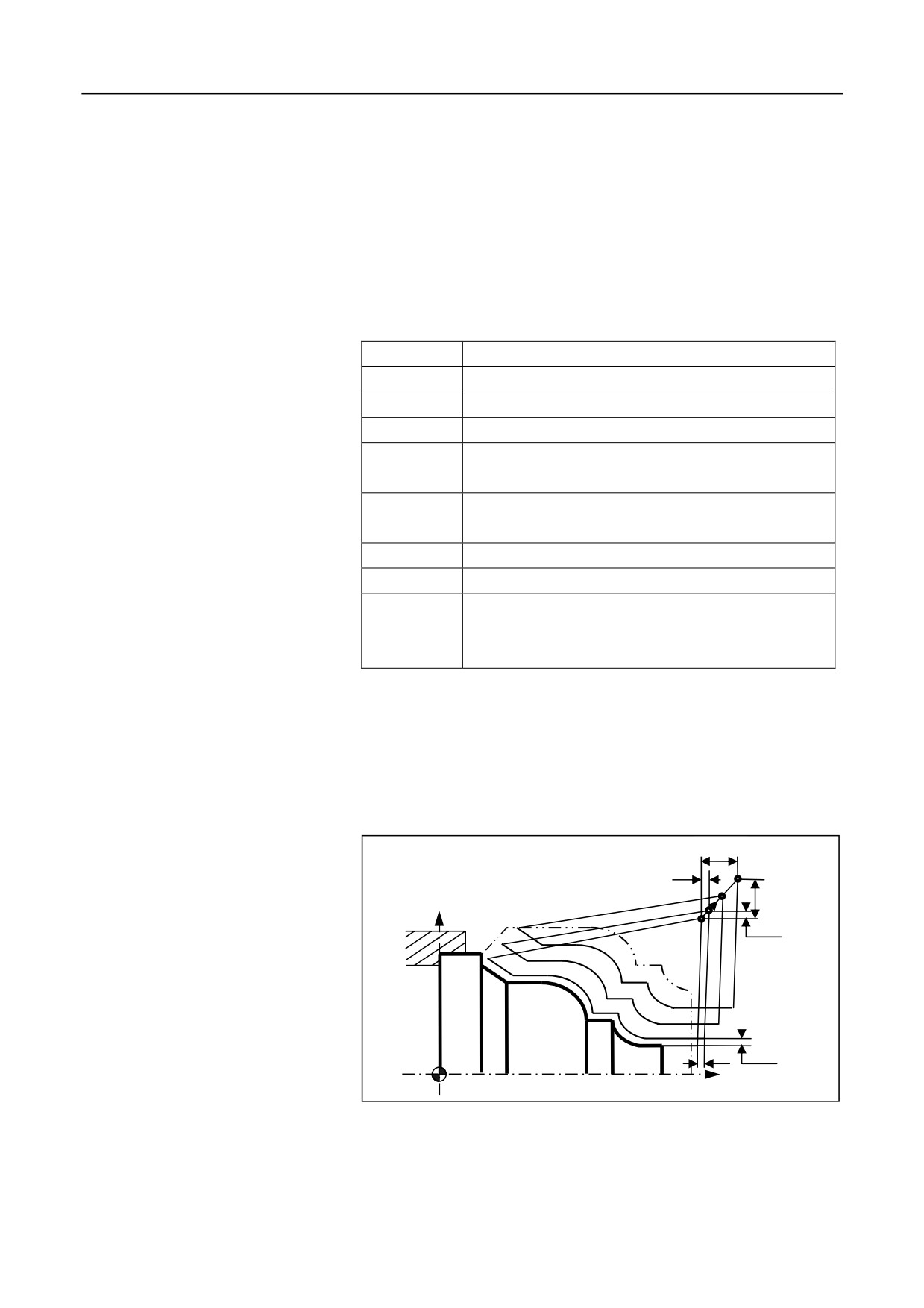
Description
instruction is a closed loop shown in the figure below. The tool feeds
gradually and cuts the workpiece to the final shape step by step. The
finishing path is AĺA'ĺB'ĺB. See the figure below:
Δk+Δz
ǻz
A
+X
ΔI+Δx/2
A
ǻx/2
A’
A’
●
ǻz ǻx/2
The tool path specified by the
275