HNC-818. User Manual - page 11
13. User Macro Program
G91 G01 Z10 F400
M98 P123; call subprogram O123
G4X1
M30
Subprogram O123
%1234;
G01x10y10z10
…
G80
M99
Fixed cycle
There are two kinds of fixed cycles. One is the general fixed cycle,
mainly used for turning, milling and drilling; the other is the user fixed
cycle, which is created by yourself according to your requirements.
For detailed information about general fixed cycle, see section 12.
For user-defined fixed cycle
(USERDEF.CYC), you may add
subprograms to this file as required, and may directly call them in the
main program.
Open the user-defined fixed cycle file "USERDEF.CYC", find the
content as below, and add subprograms after it, e.g. add 1010:
The fixed cycle below is a user-defined fixed cycle:
User-defined fixed cycle ranging from G1000 to Gxxxx by tp
2010.12.27
User-defined fixed cycle G1090
%1010
G01X10Y10
M99
307
14. Spindle Functions
14 Spindle Functions
This chapter includes the following sections:
14.1 Constant Linear Speed Cutting Control
14.2 C/S Axis Change Function
308
14. Spindle Functions
14.1 Constant Linear Speed Cutting Control (T) (G96, G97)
Specifies the circumferential speed (relative speed between the tool and
the workpiece) after S. With respect to the tool position change, rotate
the spindle at specified circumferential speed all the time.
Format
constant linear speed control
G46 X_ P_; limit spindle speed
G97 S_ ; cancel the spindle constant linear speed control
Parameter
Description
P
In G96 command: It specifies the axis for the constant
linear speed control. The axis specified by
0 is
determined by the system axis parameter. The values
1, 2, and 3 indicate the X, Y and Z axis respectively.
In G46 command: It specifies the maximum spindle
speed
(r/min) limitation when the constant linear
speed is defined by G46.
S
Define the constant linear speed in G96 (mm/min or
inch/min).
The defined spindle speed (r/min) after the constant
linear speed is canceled in G97.
X
The minimum spindle speed (r/min) limitation when
the constant linear speed is defined.
G96 P_ S_ ; enable the spindle
Description
which can be canceled by each other.
2.
G46 is valid only when the constant linear speed function is valid.
3.
Only when the spindle can automatically change speed (e.g.: servo
spindle, frequency spindle), can the constant linear speed function
be used.
4.
During the constant linear speed control, when the spindle speed
exceeds the maximum spindle speed, it will be limited at the
maximum speed.
1.
G96/G97 are modal commands
Attention
309
14. Spindle Functions
G96 must be followed by G46, to
limit the maximum and minimum
spindle speed.
310
14. Spindle Functions
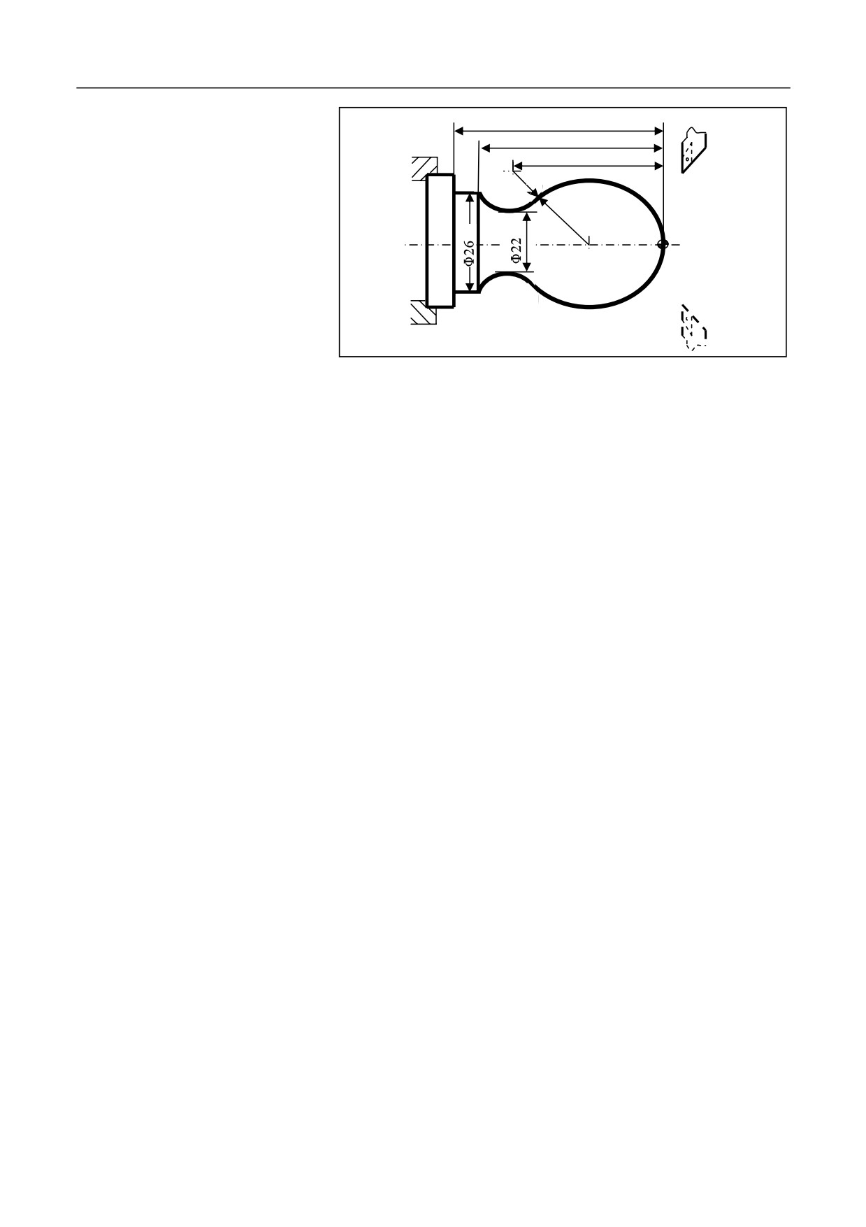
Example
40
31
27
R5
R15
%3318
N1 T0101; Select No. 1 tool and define coordinate system
N2 G00 X40 Z5; Go to the start point
N3 M03 S460; Rotates spindle at 460r/min
N4 G96 P0 S80; The constant linear speed is valid, with the speed of
80m/min).
N5 G46 X400 P900; Limit the spindle speed range: 400-900 r/min
N6 G00 X0; The tool goes to the center, and the spindle speed increases
until the maximum speed 900r/min.
N7 G01 Z0 F60; Close to the workpiece
N8 G03 U24 W-24 R15; Conduct machining for the arc of R15
N9 G02 X26 Z-31 R5; Conduct machining for the arc of R5
N10 G01 Z-40; Conduct machining for the outer circle of ĭ26
N11 X40 Z5; Back to the tool setting location
N12 G97 S300; Cancel the constant linear speed function, and rotate the
spindle at the speed of 300r/min
N13 M30; Stop spindle, end the main program, and reset
311
18. Spindle Functions
14.2 C/S Axis Switching Function (CTOS/STOC)
In complex applications, such as rigid tapping function, the spindle need
to be used as a rotation axis in addition to a spindle. In this case, the C/S
axis switching function is available.
Format
STOC/G108 IP;
CTOS/G109 IP;
Parameter
Description
IP
IP can be defined as A/B/C. The number following it
indicates the channel spindle number, which ranges
from 0 to 3.
When IP is not specified after STOC, No. 0 spindle
will be switched to the C axis by default.
When IP is not specified after CTOS, the C axis will
be switched to No.0 spindle by default.
Attention
1.
In the same G code, it is not recommended to frequently use the
STOC/CTOS macro commands
2.
When the spindle is switched to the C axis, the unit of the C axis is
deg/min.
3.
It is not allowed to use the random line function to jump among
lines between STOC and CTOS, or jump from other line to a line
between STOC and CTOS.
4.
The random line function does not support the C axis of STOC.
Example
%900 Program name
G54
M03S600
STOC; Switch the spindle to the C axis
G28 C0; The C axis returns to the origin.
G1 C45 F2000
312
14. Spindle Functions
…
CTOS; Switch the C axis to the spindle
M03S600
M30
Attention
M30 cannot restore the status of the C/S axis.
14.3 Spindle Synchronization (G116, G117)
During dual spindle synchronization, one spindle is the master axis, and
the other is the slave axis. The reference spindle for synchronization is
called the master axis, while the axis moves with the master axis is called
the slave axis. During polygon machining, the tool axis is the master axis,
and the workpiece axis is the slave axis.
Format
G116 J_/K_ P_/Q_ R_; establish synchronization
G117; cancel synchronization
Parameter
Description
J
The logical axis number of the master axis.
K
The logical axis number of the slave axis.
P
The rotation speed ration of the master axis, ranging
from 1 to 1000.
Q
The rotation speed ration of the slave axis, ranging
from -1000 to 1000 and cannot be 0.
When Q is a positive value, the rotation direction of
the slave axis is the same as that of the master axis.
When Q is a negative value, the rotation direction of
the slave axis is opposite to that of the master axis.
R
Phase angle (0 to 360)
Example
T0101
G0 X100 Z20
M3 S1000
313
18. Spindle Functions
G116 J5 K1 P1 Q2 R0; Establish
synchronization. No.5 logical axis is
the master axis and No.1 logical axis
is the slave axis.
G04 X2
G01 X20 F100; Conduct tool feed
G0 X100; Exit the tool
for cutting
G117; Cancel synchronization
M5
M30
Attention
1.
The spindle synchronization commands (G116/G117) cannot be
used with other commands simultaneously in one line.
2.
During synchronization, you can not specify the metric conversion
commands (G20, G21).
3.
The Emergency Stop and Reset command can automatically cancel
the synchronization.
4.
During synchronization, you cannot control the slave axis with
commands. Only the rotational speed and direction of the master
axis can be specified. But you may specify movement commands
for other axis through the programming.
314
15. Programmable Data Input
15 Programmable Data Input
You can dynamically modify system data in the program via
programmable data input.
1.
Change the origin of the workpiece coordinate system
2.
Change the origin of the extended workpiece coordinate system
315
15. Programmable Data Input
15.1 Programmable Data Input (G10, G11)
You can dynamically modify system data in the program with
G10/G11.The modified system data takes effect immediately.
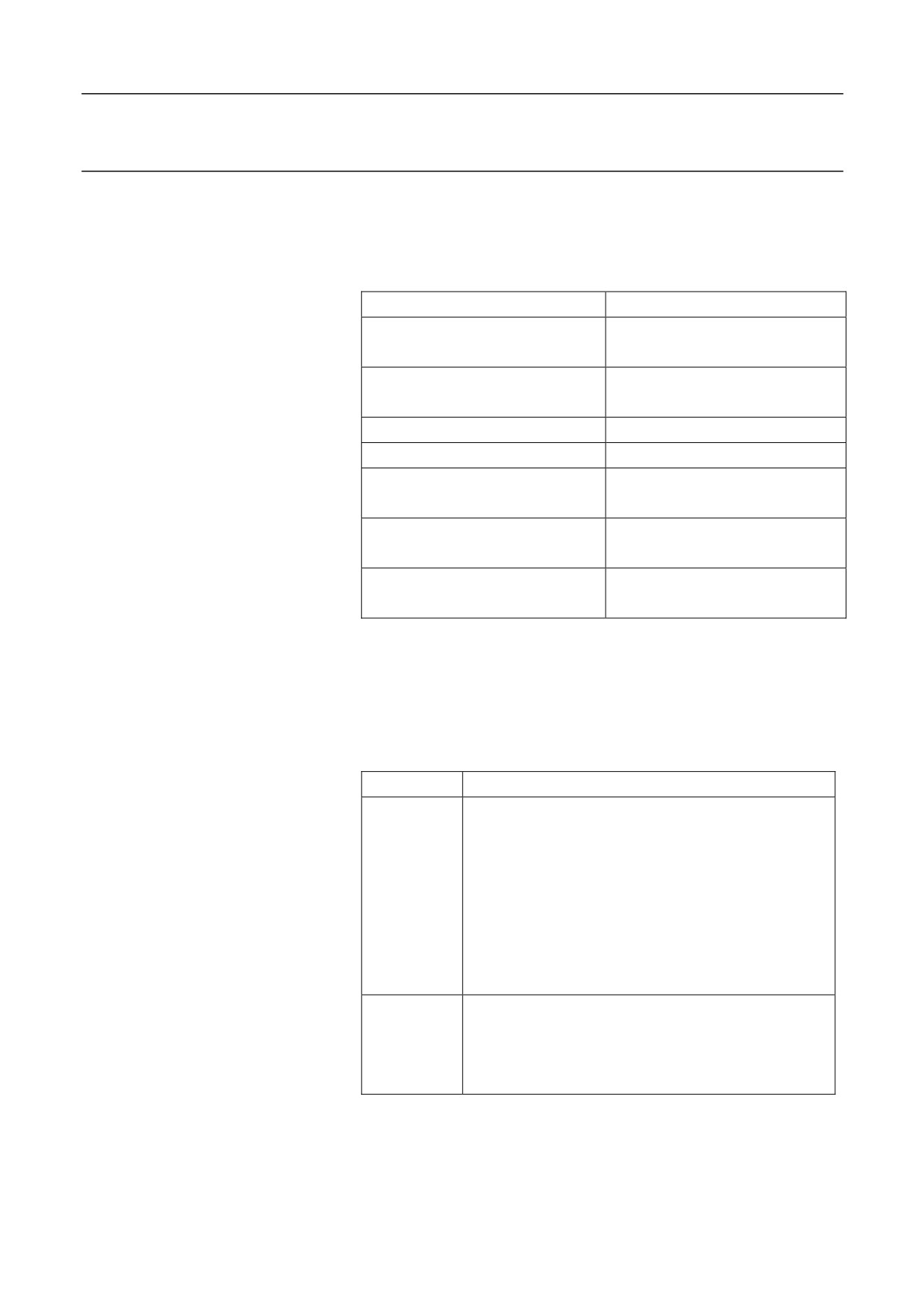
Format
Function
G Code
G54-G59: the origin of the
G10 L2 Pp IP_
workpiece coordinate system
G54.X: the origin of the extended
G10 L20 Pp IP_
workpiece coordinate system
System parameter output
G10 L53 PpRr
Cancel user-defined input
G11
Milling tool geometry
G10 L10 PpRr
compensation value H input
Milling tool geometry
G10 L12 PpRr
compensation value D input
Turning tool compensation value
G10 L14 Pp X_ Z_ R_ Q_ Y_ J_
input
K_
Description
G10 is a modal command, which enables the programmable data input
mode until it is canceled by G11.
G54-G59 origin of the workpiece
G10 L2 Pp IP_
coordinate system
Parameter
Description
Pp
Specify the workpiece origin offset in the relative
workpiece coordinate systems from 1 to 6:
y
1 indicates the G54 workpiece coordinate system
y
2 indicates the G55 workpiece coordinate system
y
3 indicates the G56 workpiece coordinate system
y
4 indicates the G57 workpiece coordinate system
y
5 indicates the G58 workpiece coordinate system
y
6 indicates the G59 workpiece coordinate system
IP
The workpiece origin offset of each axis for absolute
commands.
Added to the workpiece origin offset of each axis for
incremental commands.
Example 1
%0002
316
15. Programmable Data Input
G54; Initial value of G54
G01X100Y100Z100
G10L2P1X100Y100Z50; Change the origin of the G54 workpiece
coordinate system to (100, 100, 50)
G11
G01X20Y20Z20; The command value of the machine coordinate system
is (120, 120, 70).
M30
G54.X origin of the extended
G10 L20 Pp IP_
workpiece coordinate system
Parameter
Description
Pp
Set the code p for the workpiece coordinate system of
the workpiece origin offset: 1-60, corresponding to the
X value in the G54.X coordinate system.
IP
The workpiece origin offset of each axis for absolute
commands.
Added to the workpiece origin offset of each axis for
incremental commands.
Example 2
%0002
G54.1
G01X100Y100Z100
G10L20P1X100Y100Z50; Change the origin of the G54.1 workpiece
coordinate system to (100, 100, 50)
G11
G01X20Y20Z20
M30
Attention
In the turning system and in the diameter programming mode, the X
value specified by G10 is the radius value.
System parameter output
Output the system parameter to the current channel variables specified
317
15. Programmable Data Input
by Rr: #0 to #49
G10 L53 Pp Rr
Parameter
Description
Pp
Index of parameter ID
Rr
Variable address (0 to 49)
Cancel user-defined input
G11
Example 3
Use machine user parameters from P40 to P48
Parameter number 010340 to 010348
As the parameter P ranges from 500000 to -500000, you may use it if the
error range is wide.
G54
G01X0Y0Z0
G10L53P010340R1
G10L53P010341R2
G10L53P010342R3
G10L53P010343R4
G10L53P010344R5
G10L53P010345R6
G10L53P010346R7
G10L53P010347R8
G10L53P010348R9
G11
G01X[#1/1000]Y[#2/1000]Z[#3/1000]
G01X[#4/1000]Y[#5/1000]Z[#6/1000]
G01X[#7/1000]Y[#8/1000]Z[#9/1000]
M30
318
15. Programmable Data Input
Milling tool geometry compensation value H input
G10 L10 Pp Rr;
Parameter
Description
Pp
Tool offset number
Rr
Tool compensation data
Milling
tool
geometry
G10 L12 Pp Rr;
compensation value D input
Parameter
Description
Pp
Tool offset number
Rr
Tool compensation data
Turning tool compensation input
G10 L14 Pp X_ Z_ R_ Q_ Y_ J_ K_;
Parameter
Description
Pp
Tool offset number
X
Tool compensation data X
Z
Tool compensation data Z
R
Tool nose compensation R
Q
Imaginary too nose direction
Y
Tool compensation data Y
J
Tool radial wear J
K
Tool axial wear K
319
16. Axis Control Functions
16 Axis Control Functions
This chapter includes the following sections:
16.1 Cycle Function of the Rotation Axis
16.2 Reference of the Grating Ruler with Distance-Code
320
16. Axis Control Functions
16.1 Cycle Function of the Rotation Axis
Overview
The rotation axis cycle function can be used to prevent the overflow of
the rotation axis coordinate value.
You may enable the rotation axis cycle function by setting relevant
parameters.
Take the C axis as an example, you need to set the parameter AXIS
TYPE (104001) of axis 4 to 3 in the coordinate axis parameters , and set
the parameter FEEDBACK POS CYCLE ENABLED (505014) of the
corresponding device to 1in the device interface parameters.
Description
For incremental commands, the movement amount is the command
value.
For absolute command, you may set the parameter R-AXIS SHORT
PATH SELECTION EN (104082) of the corresponding axis to 1 in the
coordinate axis parameters, and set the rotation direction of the rotation
axis to the direction of the short path from the start point to the end point.
Example
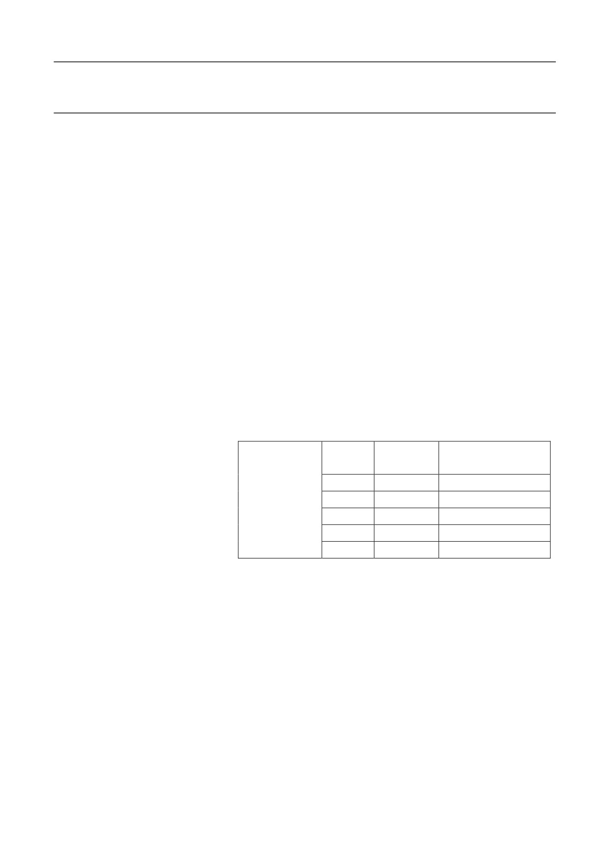
G90 C0
Sequence
Actual
Absolute Coordinates
N1 G90 C-150.0
No.
Movement
after Movement
N2 G90 C540.0
N1
-150
210
N3 G90 C-620.0
N2
-30
180
N4 G91 C380.0
N3
-80
100
N5 G91 C-840.0
N4
380
120
N5
-840
0
Attention
For some machines with rotation axis (such as working tables), due to
the mechanical structure, the rotation axis can rotate only in one
direction during movement. In this case, it is not recommended to use the
absolute command but the incremental command programming to avoid
the opposite direction of rotation caused by programming errors.
321
16. Axis Control Functions
16.2 Reference of Grating Ruler with Distance-Code
Overview
Using a linear measuring system with distance-coded reference point
symbols, you do not need to install a deceleration switch on the machine
for returning to the reference point, and the machine can return to a fixed
machine reference point. It makes the operation much faster and easier in
the actual use.
Principle
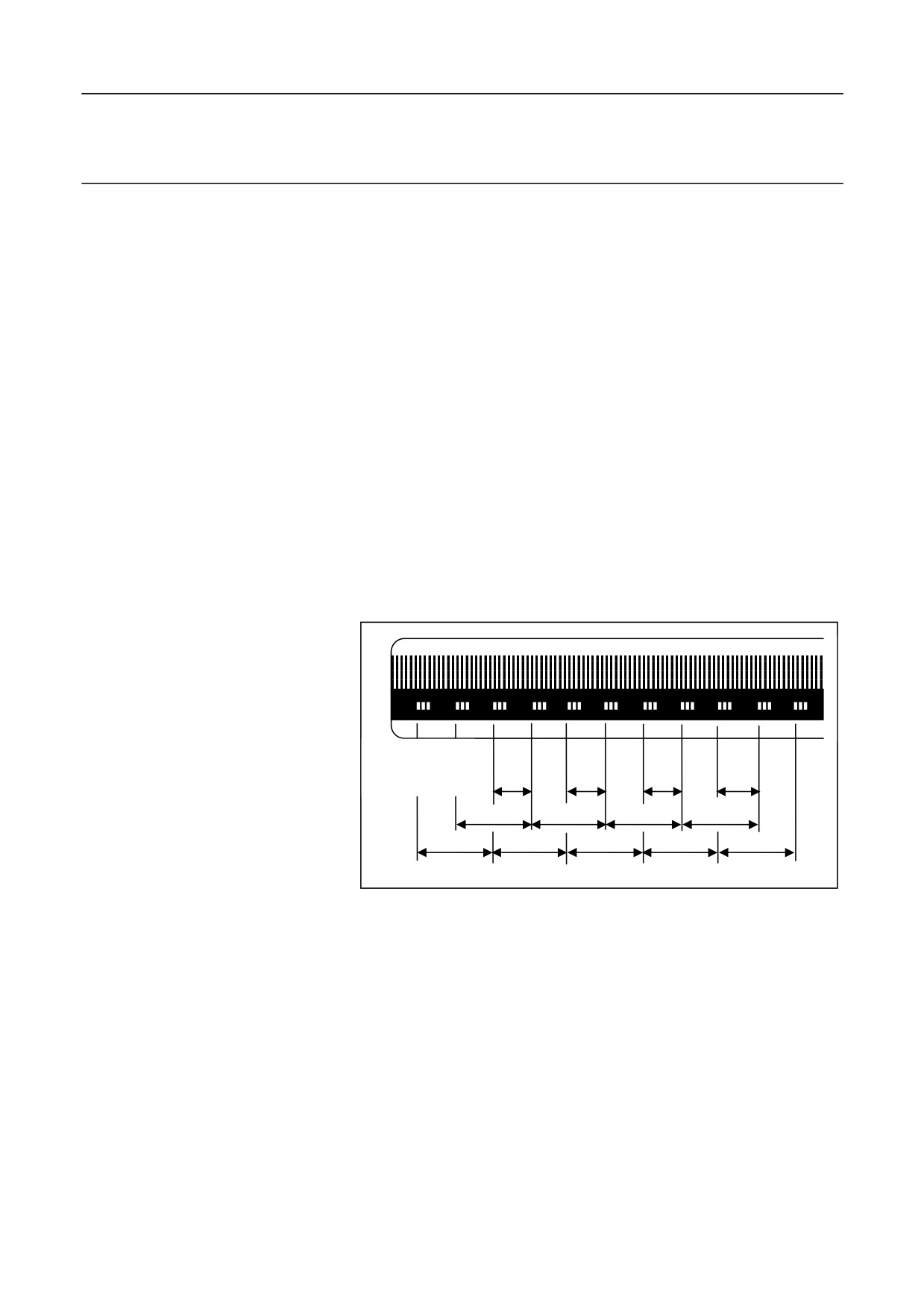
The principle for the linear measuring system with distance-coded
reference point symbols is to adopt a standard linear grid line and a
channel with distance-coded reference point symbols which is parallel to
the linear grid line. The distance between two reference point symbols in
the same group is the same, but the distance between the adjacent
reference point symbols of two different groups is variable. Each
segment distance plus a fixed value, then the CNC axis can determine
the absolute position according to the distance. See the figure below
(example: LS486C):
Reference point
symbol
10.04
10.06
10.08
10.10
10.02
20.02
20.02
20.02
20.02
20
20
20
20
20
A
B
C
D
E
For example, the machine moves from point A to point C through the
middle point B. If the system detects
10.02
, it will know which
reference point the axis is at. Similarly, when the machine moves from
point B to point D through the middle point C and the distance from the
point C to point D is 10.04, the system will know which reference point
the axis is at. Therefore, if the axis moves more than two reference points
(20 mm), the system will be able to get the absolute position of the
machine.
322
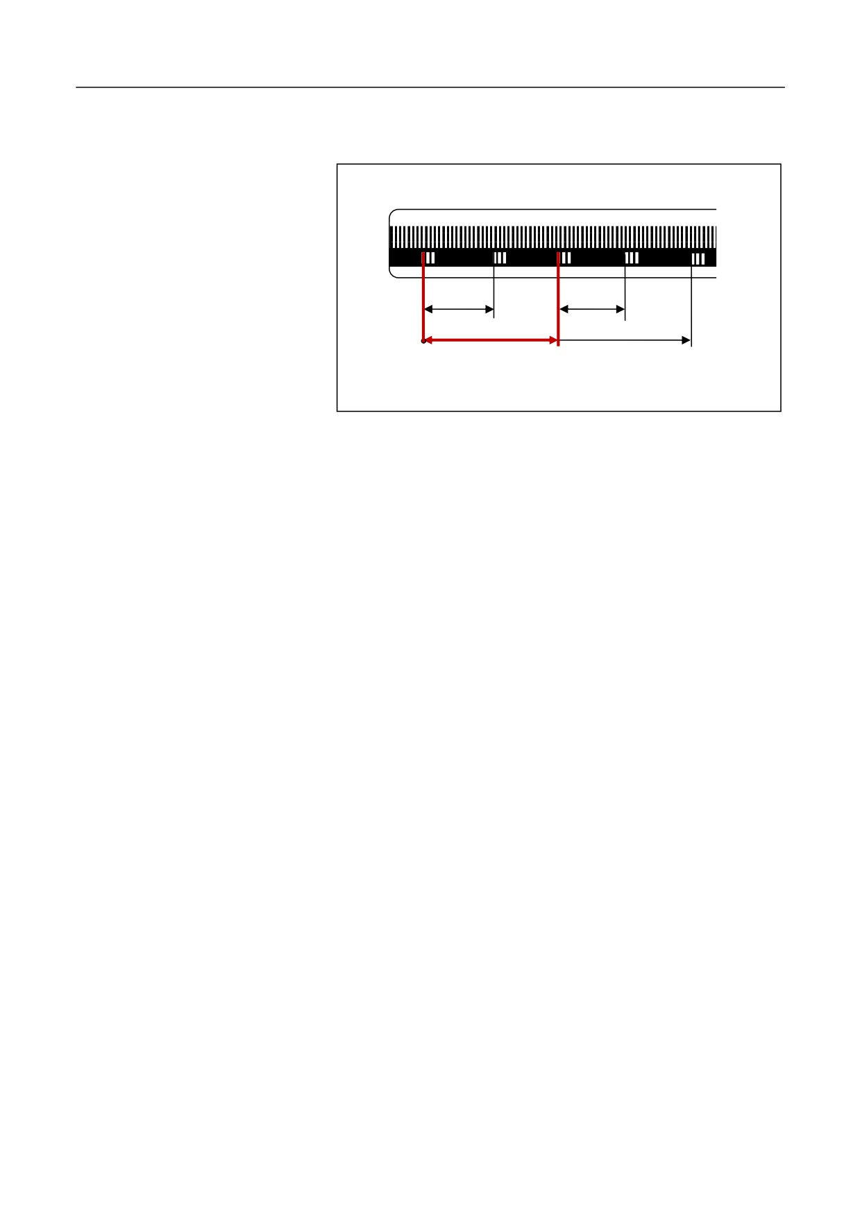
16. Axis Control Functions
Parameter settings
Take the X-axis as an example to illustrate the parameter settings for
linear grating ruler with distance code:
10.02
10.04
Distance between
0
20
40
distance-coded
reference points
1.
Setting reference returning mode
Set the parameter REF POINT RETURN MODE (100010) of the
axis 0 in coordinate axis parameters to 4 when the feedback from
the distance-code is in the same direction of reference returning;
otherwise set it to 5.
2.
Setting distance between distance-coded reference points
Set the parameter DISTANCE CODE REF SPACE(mm) (100018)
of the axis 0 in coordinate axis parameters. This parameter indicates
the distance between two adjacent distance-coded reference points
in the incremental measuring system. As shown in the figure above,
the distance between two distance-coded reference points is set to
20.
3.
Setting distance-code offset
Set the parameter DISTANCE CODE DEVIATION(mm) (100019)
of the axis 0 in coordinate axis parameters. This parameter indicates
the incremental interval between distance-coded reference points in
the incremental measurement system. As shown in the figure above,
it indicates the incremental value
0.02 from
10.02 to
10.04.
Therefore, the distance-code offset is set to 0.02.
4.
Setting reference point zero
After the distance code is returned to the zero point, return a defined
point to the zero point, and set this point to the machine zero. Then
set the coordinate value after the current point is returned to zero for
REF POINT POS(mm) (100017) of the coordinate axis 0. This
point will be used as the machine origin to define coordinate system
when you return a point to the zero point next time.
323
17. Other Functions
17 Other Functions
This chapter includes the following sections:
17.1 Stop Read-ahead (G08)
17.2 Redefine Rotation Axis Angle Resolution (G115)
17.3 Axis Release (G101)
17.4 Command Channel Loader (G103) and Running (G103.1)
17.5 Channel Synchronization (G104)
17.6 Alarms (G110)
324
17. Other Functions
17.1 Stop Read -ahead (G08)
During program execution, the system stops interpreting the subsequent
lines after encountering this command. Only after the previously
interpreted commands are completed, the system proceeds to interpret.
This command is also used for real-time coordinate reading and state
judgment.
Format
G08 ; specify this command in a separate program line.
Example
%0003
G54
G01 X10 Y10 Z10
G08; stop interpretation
G01 X100Y100Z100
G01 X30
M30
325
17. Other Functions
17.2 Redefine Rotary Axis Angle Resolution (G115)
Format
G115 IP_
Paramter
Description
IP
Set the reciprocal value for the rotary axis resolution.
When it is set to 0, the system restores the default
angle resolution. It must be greater than 0.
Description
Modify the rotary axis resolution. The default value is 1/100000 degree.
There should be greater angle increments in one instruction during rigid
tapping. Therefore, you need to decrease the angle resolution to an
appropriate degree, to make sure that the equivalent length will not
exceed the limit.
Attention
1.
This command must be specified in a separate row.
2.
One command can be used to modify only one rotary axis
instruction.
3.
The specified axis must be a rotary axis.
4.
The newly defined angle resolution must be divisible by the
standard one.
Example
%1234
STOC
G54
G90 C0
G115 C 1000; change the C axis resolution to 1/1000 degree.
G01 C3000
G115 C0; restore the C axis resolution to the default 1/100000 degree.
CTOS
326
17. Other Functions
17.3 Axis Release (G101) and Axis Obtaining (G102)
Format
G101 IP_
Parameter
Description
IP
Set the axis to be released. Options:
X/Y/Z/A/B/C/U/V/W/S0/S1/S2/S3
G102 IP_
Parameter
Description
IP
Set the axis to be obtained. Options:
X/Y/Z/A/B/C/U/V/W/S0/S1/S2/S3
Description
G101 is used to release the axis by the channel. The address word
following G101 can be any numbers, but it is recommended to specify it
as 0.
G102 is used to obtain the axis by the channel. The address word
following G102 must be a logical axis number.
Attention
1.
Generally, the same logical axis can belong to only one channel at
the same time.
2.
After a channel obtains an axis, you need to set the G5X origin of
the axis. If it cannot be specified on the settings interface, you may
use G10 to specify it.
3.
Axis release or obtaining cannot be executed during axis movement.
327
17. Other Functions
Example
How is drilling executed in the X/Y axis direction on the milling
machines? In the example as below, assuming that in the channel
configuration, the logical axis number of the X axis is 0, the logical axis
number of the Y axis is 1, and the logical axis number of the Z axis is 2:
%1111
G54
G101 Y0 Z0; Release the Y axis and Z axis
G102 Y2 Z1; Exchange the logical axis numbers of the Y axis and Z axis
Start drilling:
G0X0Y0Z60
M3S700
G99G73X20Y25R5P2Q-3K2Z-32F80
G0X0Y0Z60
M30
328
17. Other Functions
17.4 Command Channel Loader (G1030) and Running (G103.1)
Format
G103 P="program name" Q={channel number,...}
Parameter
Description
P
The name of the program to be loaded.
Q
The number of the channel where the program will be
loaded. Separate multiple channels with a comma
symbol (,).
G103.1 Q={channel number,...}
Parameter
Description
Q
The number of the channel where the program will
run. Separate multiple channels with a comma symbol
(,).
Description
When G103.1 is executed, the channel where the program will be loaded
must be in the auto mode.
When G103 is executed, the channel where the program will be loaded
should not have selection programs.
These two commands are generally used for multi-channels.
Example
Assuming that there is a dual-channel machine, channel 1 makes channel
2 load and run program O01.
%1
N1 G54
N2 G103 P="O01" Q={2}
N3 G103.1 Q={2}
.......;
M30
When channel 1 completes the line N3, channel 2 starts to run O01.
329
17. Other Functions
17.5 Channel Synchronization (G104)
Format
G104 P_ Q={channel number,}
Parameter
Description
Q
The number of the channel to be synchronized.
Separate multiple channels with a comma symbol (,).
P
Signal value, ranging from 0 to 40.
Description
G104 is generally used for the process synchronization of multiple
channels.
Example
Assuming there is a dual-channel milling machine, and the X axis is the
public axis, with the following configuration:
Logical Axis No. of
Logical Axis No. of
Channel 0
Channel 1
X axis
0
---
Y axis
1
3
Z axis
2
4
Programs of Channel 1
Programs of Channel 2
%1
%2
N1G54X0Y0Z0
N1G104
P1
Q={1,2};
N2G02X10Y10R20
synchronization statement 1
N3G1X0Y0Z0
N2G102 X0; obtain X axis
N4G101 X0; release X axis
N3G54X0Y0Z0
N5G104
P1
Q={1,2};
N4G02X10Y10R20
synchronization statement 1
N5G0X0Y0Z0
N6G104
P2
Q={1,2};
N6G101 X0; release X axis
synchronization statement 2
N7G104
P2
Q={1,2};
N7G102 X0
synchronization statement 2
N8G0X100
N8M30
N9M30
As listed in the table above, channel 1 and 2 load their own programs
330
17. Other Functions
and start the cycle.
1.
Channel 1 executes N1 to N4, and channel 2 waits at N1.
2.
Channel 1 executes N5, and channel 2 can execute downward.
3.
Channel 1 waits at N6, and channel 2 executes N2 to N6.
4.
Channel 2 executes N7, and channel 1 cam execute downward.
5.
Channel 2 executes N8, and channel 1 proceeds to execute N7 to
N9.
331
17. Other Functions
17.6 Alarms (G110)
Format
G110 P_
Parameter
Description
P
Alarm code, which must be a negative value.
Attention
User-defined alarm codes: -8000 to -9999
You may write alarm information as required, which will be saved in
USR_SYTAX.TXT (all uppercase). The format is as below:
-8000 milling cycle: The tool is not defined.
-8001 milling cycle: The reference plane is not defined.
……
……
Write the following statement in the G codes:
G110 P-8000; when the system executes this line, an alarm indicating the
tool is not defined will be reported.
332