HNC-8 Numerical Control System Software. Maual of PLC Programming (V1.24) - page 9
HNC-8-PLC Component specification
6. Extended function module
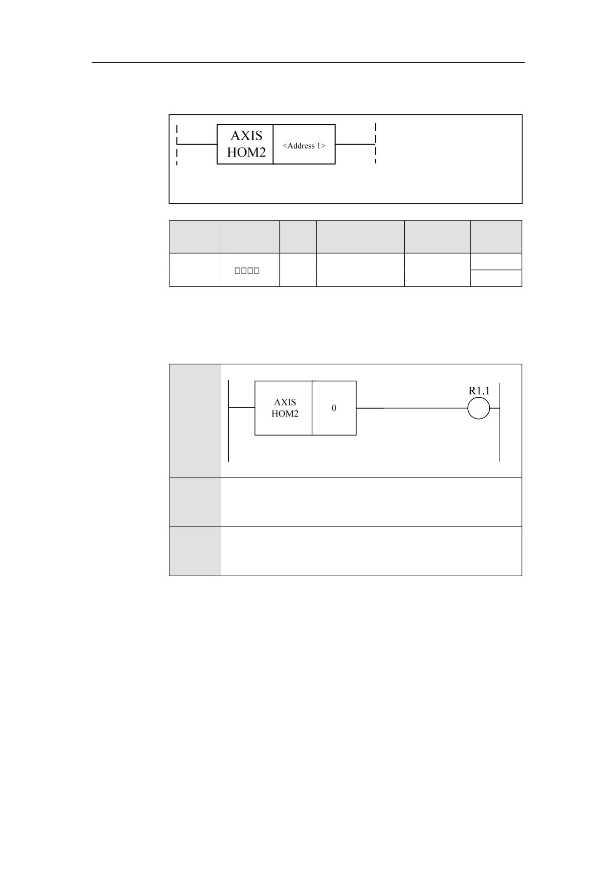
During Axis Home AXISHOM2
Format
Paramet
Parameter
Data
Properti
Storage area
Explanation
er
form
type
es
<Addres
Axis
Pre ○
INT
Constant
s 1>
number
Post ○
Function
To get the home status while the axis is returning home. In the process of axis
home, some operations cannot be performed, in which case the home status must
be judged. The corresponding F status word is F0.2.
Example
Ladder
Diagram
Stateme
AXISHOM2 0
nt List
Descripti
The home sign of axis 0 is valid. While the axis is returning home,
on
R1.1 is output, where other manual operations are not allowed.
234
HNC-8-PLC Component specification
6. Extended function module
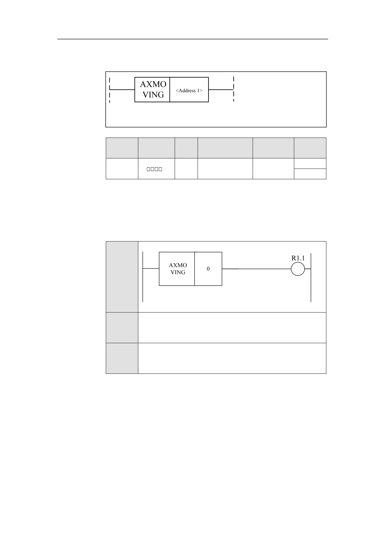
During Axis Moving AXMOVING
Format
Paramet
Parameter
Data
Properti
Storage area
Explanation
er
form
type
es
<Addres
Axis
Pre ○
INT
Constant
s 1>
number
Post ○
Function
To get the axis status during its movement. In the process of axis moving, some
operations cannot be performed, in which case the status must be judged. The
corresponding F status word is F0.0.
Example
Ladder
Diagram
Stateme
AXMOVING 0
nt List
Descripti
The moving sign of axis 0 is valid. While the axis is moving, R1.1
on
is output.
235
HNC-8-PLC Component specification
6. Extended function module
System Function
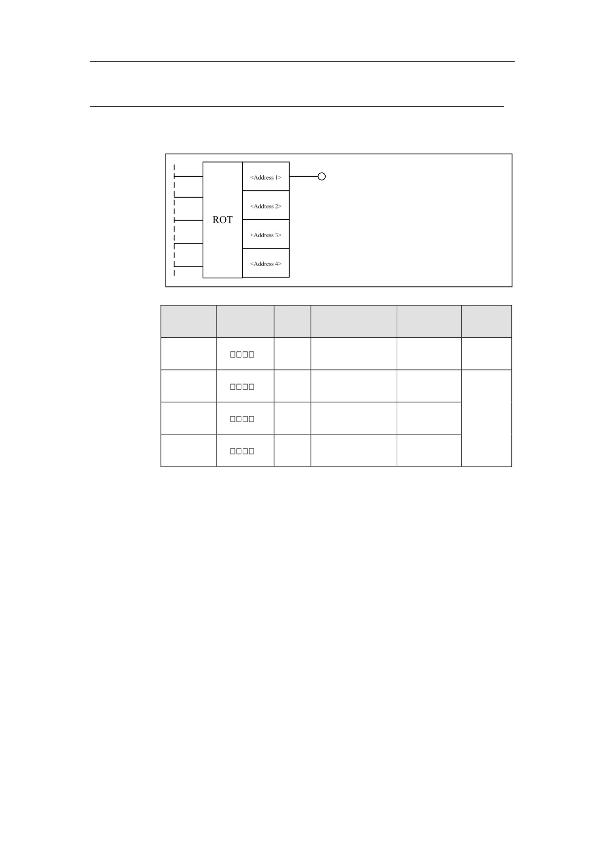
Rotation ROT
Format
Paramete
Parameter
Data
Properti
Storage area
Explanation
r
form
type
es
<Address
INT
Constant
Pre ○
1>
<Address
X, Y, F, G, R, W,
INT
2>
D, P, B
<Address
X, Y, F, G, R, W,
INT
Post √
3>
D, P, B
<Address
X, Y, F, G, R, W,
INT
4>
D, P, B
Function
Rotation control, which is used for tool rest and the like. The output is 0 for the
rotation in the clockwise direction, and the output is 1 for the rotation in the
counter clockwise direction.
Parameter
Input 1: enable on/off
Input 2: starting number. If the number is 0, the position number of rotational
equipment starts from 0; if the number is 1, the position number of rotational
equipment starts from 1.
Input 3: Whether to select a cutter nearby. If it is 0, the cutter will be selected in
the clockwise direction; if it is 1, the cutter will be selected nearby.
Input 4: target location type. When the value is 0, the current target location is
counted; when the value is 1, the previous location of target is counted.
236
HNC-8-PLC Component specification
6. Extended function module
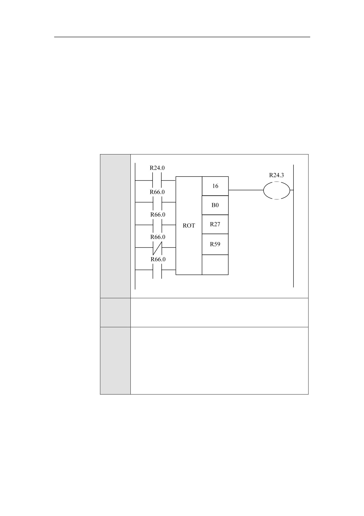
Count result. The value of 0 represents the number of count locations, and the
value of 1 represents the count steps.
Parameter 1: maximum quantity of cutter rests.
Parameter 2: address of current position.
Parameter 2: address of target position
Parameter 4: address of count result. The meaning of count result is determined
by input 4 and input 5.
Input
5:
Example
Ladder
Diagram
Stateme
ROT 16 B0 R27 R59
nt List
R66.0 is a ture contact, where the setting status of ROT module is:
start counting for the starting numbers from 1, use the function of
Descripti
short-path selecting tool, count the current target location, output
on
the counting steps, and output the counting value to R59. The
current tool location is saved in B0, and the target tool location is
saved in R27.
237
HNC-8-PLC Component specification
6. Extended function module
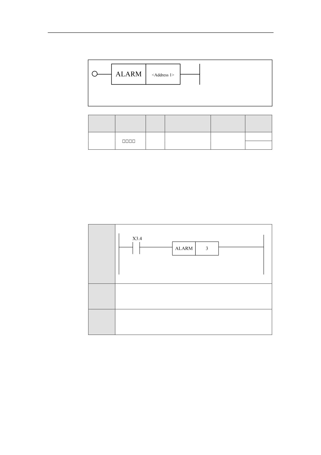
Alarm ALARM
Format
Paramet
Parameter
Data
Properti
Storage area
Explanation
er
form
type
es
<Addres
Pre ○
INT
Constant
s 1>
Post ×
Function
To generate alarm.
Parameter
Parameter 1: alarm code. The PLC alarm code is from 1 to 256, and the prompt
number of PLC is from 501 to 884.
Example
Ladder
Diagram
Stateme
ALARM 3
nt List
Descripti
When X3.4 is turned on, the alarm 3 is generated.
on
238
HNC-8-PLC Component specification
6. Extended function module
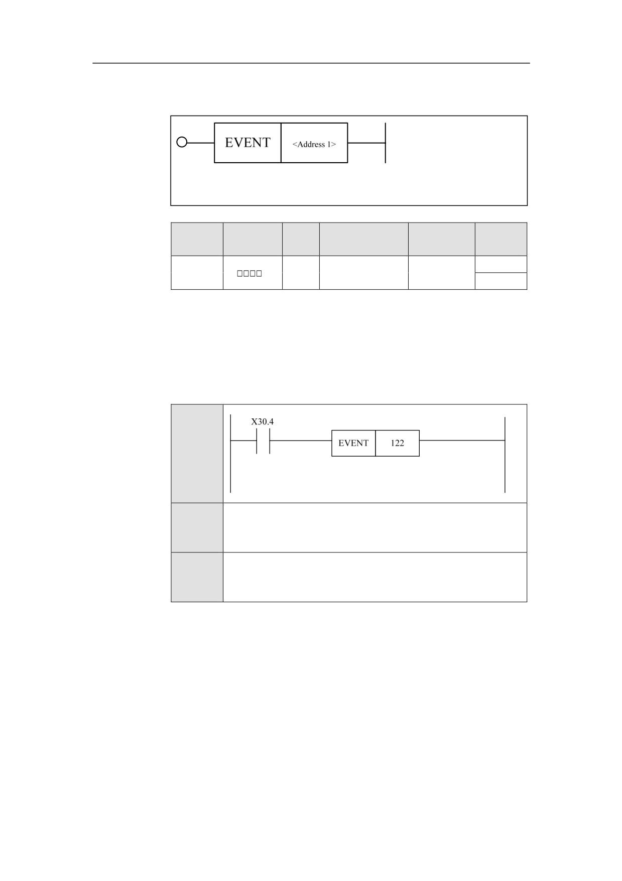
Event EVENT
Format
Paramet
Parameter
Data
Properti
Storage area
Explanation
er
form
type
es
<Addres
Pre √
INT
Constant
s 1>
Post ×
Function
To create the event object.
Parameter
Parameter 1: event number.
Example
Ladder
Diagram
Stateme
EVENT 122
nt List
Descripti
When 30.4 is turned on, the event 122 is generated.
on
239
HNC-8-PLC Component specification
6. Extended function module
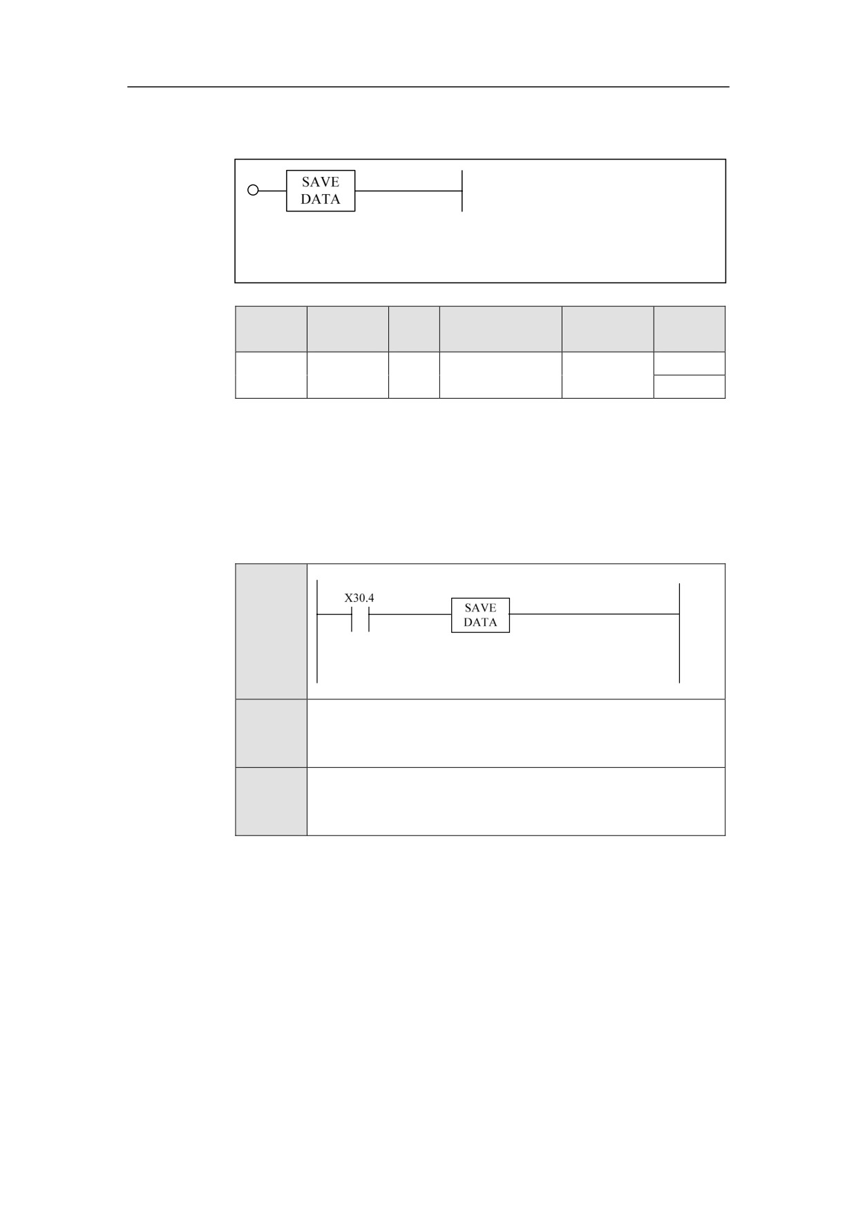
Save Data SAVEDATA
Format
Paramet
Parameter
Data
Properti
Storage area
Explanation
er
form
type
es
Pre √
None
Post ×
Function
To save all data.
Parameter
None.
Example
Ladder
Diagram
Stateme
SAVEDATA
nt List
Descripti
When X30.4 is turned on, the data, which hasn’t been saved
on
before outage, can be saved.
240
HNC-8-PLC Component specification
6. Extended function module
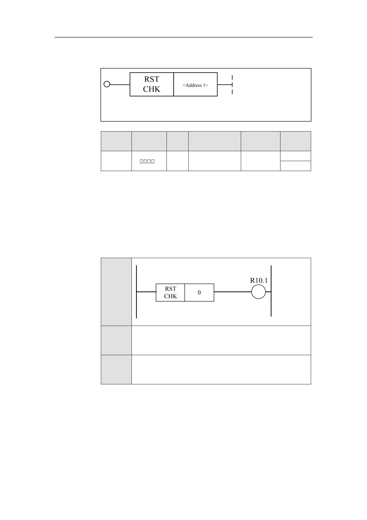
Reset Setting Ouput RSTCHK
Format
Paramet
Parameter
Data
Properti
Storage area
Explanation
er
form
type
es
<Addres
Pre √
INT
Constant
Channel No.
s 1>
Post √
Function
To get panel reset signal (must be used with RSTCLR simultaneously). If some
reset actions in PLC need to be performed after the reset button on the panel is
pressed, use this function module. “Resetting…” will be shown on the CNC
interface.
Example
Ladder
Diagram
Stateme
RSTCHK 0
nt List
Descripti
The output of setting reset is 1
on
241
HNC-8-PLC Component specification
6. Extended function module
Reset Clear RSTCLR
Format
Paramet
Parameter
Data
Properti
Storage area
Explanation
er
form
type
es
Use
it
Pre √
<Addres
together
INT
Constant
s 1>
with
Post ×
RSTCHK.
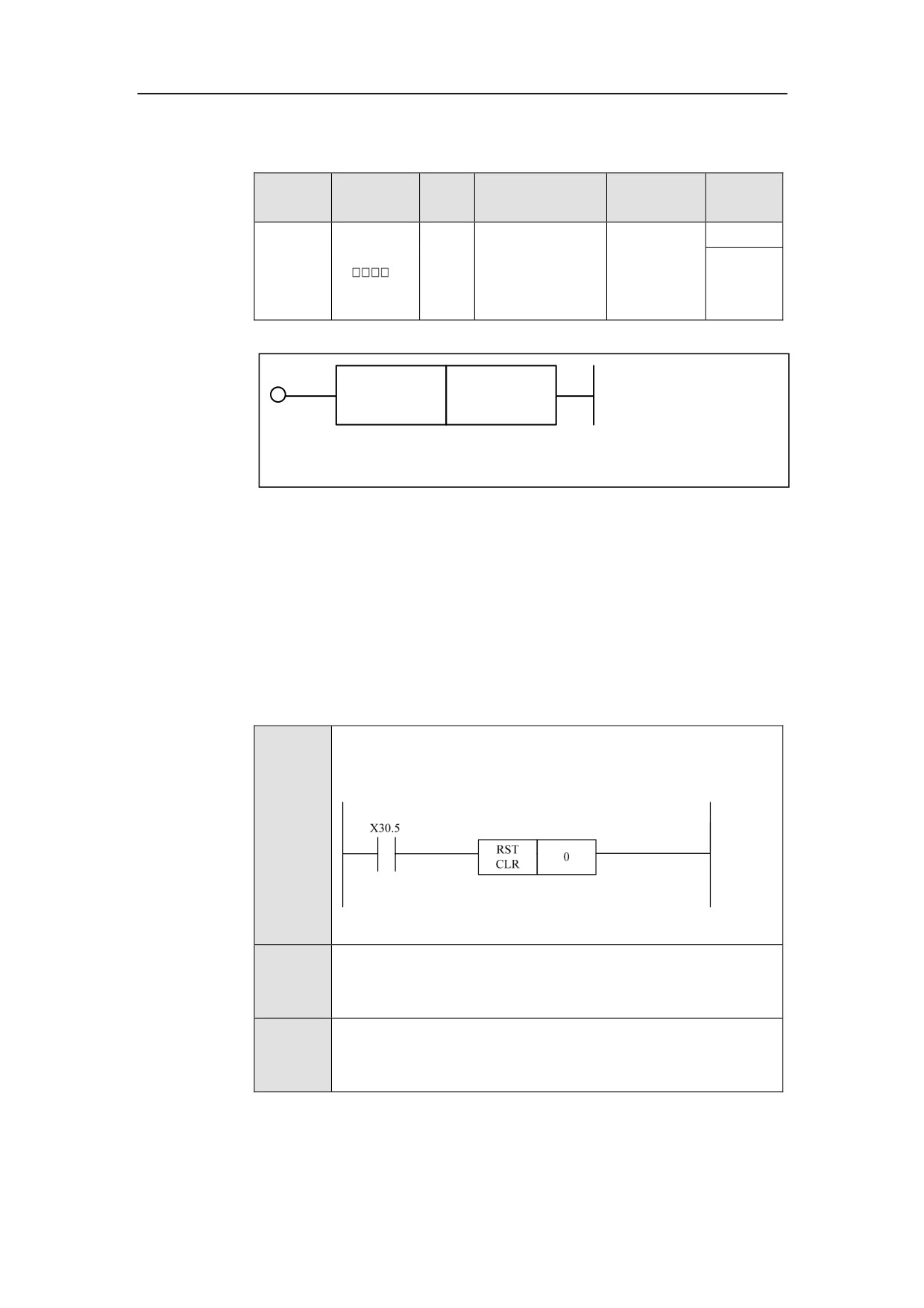
RST
<Address 1>
CLR
Function
After the reset actions in PLC are complete, the reset must be cleared (must be
used with RSTCHK simultaneously), and the signal of completing reset is
transmitted to CNC. “Reset done” will be shown on the CNC interface.
Parameter
Channel number.
Example
Ladder
Diagram
Stateme
RSTCLR 0
nt List
Descripti
When 30.5 is turned on, the reset is cleared, and the output is 0.
on
242
HNC-8-PLC Programming specification
7. Operation monitoring and online modification of ladder diagram
Operational Monitoring and Online
Modification for Ladder Diagram
The function of operational monitoring and online modification for the ladder
diagram, which is provided by PLC edit function, will monitor changes in the
status of each component in the ladder diagram, and force a modification of a
component status to achieve the goals of debugging.
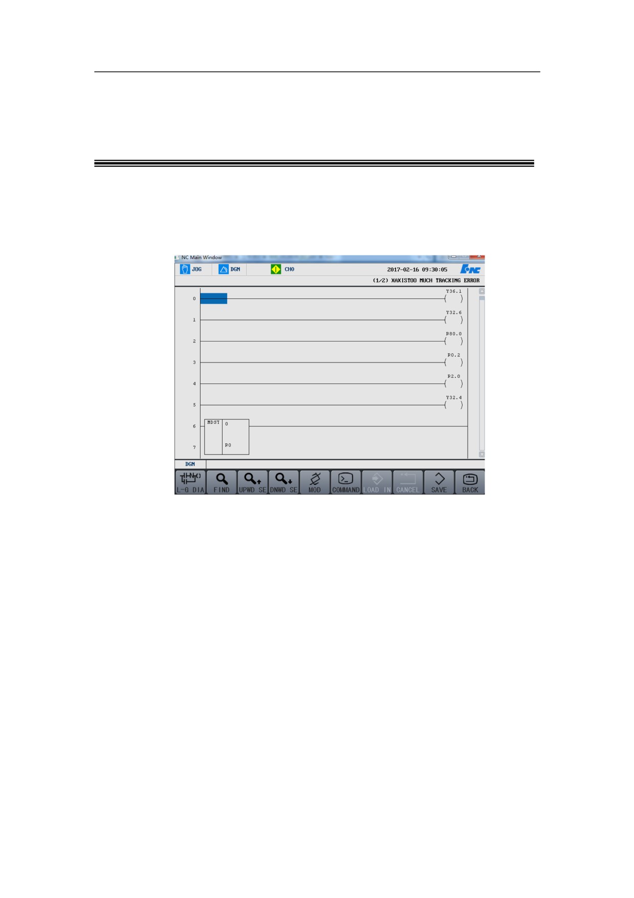
Press “Ladder diagram monitoring” on the diagnosis interface, to access the
ladder diagram interface, as seen above. The buttons on this interface include
Ladder diagram diagnosis, Search, Change, Command, Load, Discard, Save
and Return.
The next sections offer more details.
243
HNC-8-PLC Programming specification
7. Operation monitoring and online modification of ladder diagram
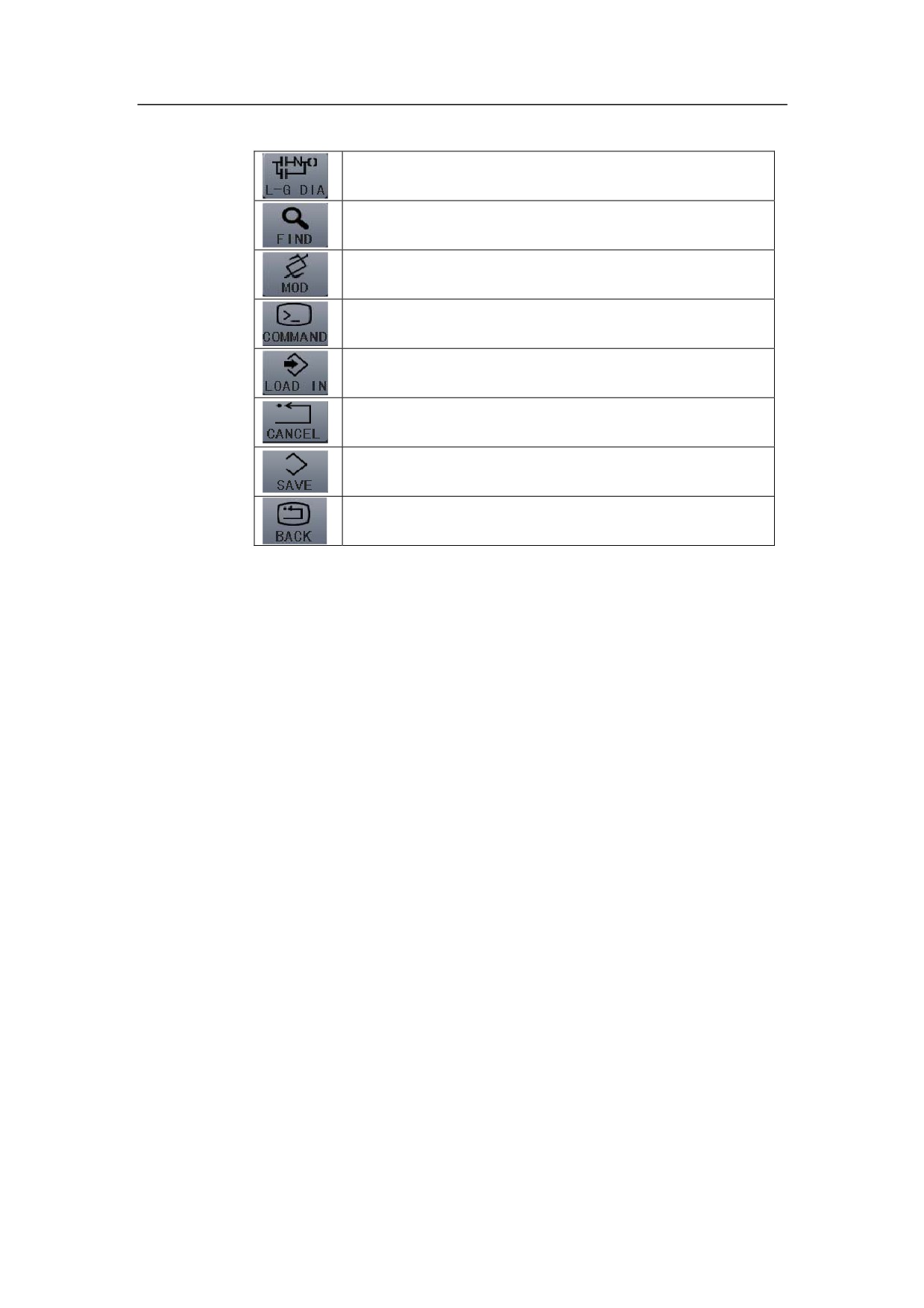
Ladder diagram diagnosis: view the value of each variable, and perform
intervention operations of component.
Search: type the component name to search the component.
Change: perform component modification operations.
Command: can edit the ladder diagram.
Load: load the current information on the ladder diagram.
Discard: undo the edits of ladder diagram.
Save: save the edits of ladder diagram.
Return: return to the previous action.
244
HNC-8-PLC Programming specification
7. Operation monitoring and online modification of ladder diagram
Online Diagnosis for Ladder Diagram
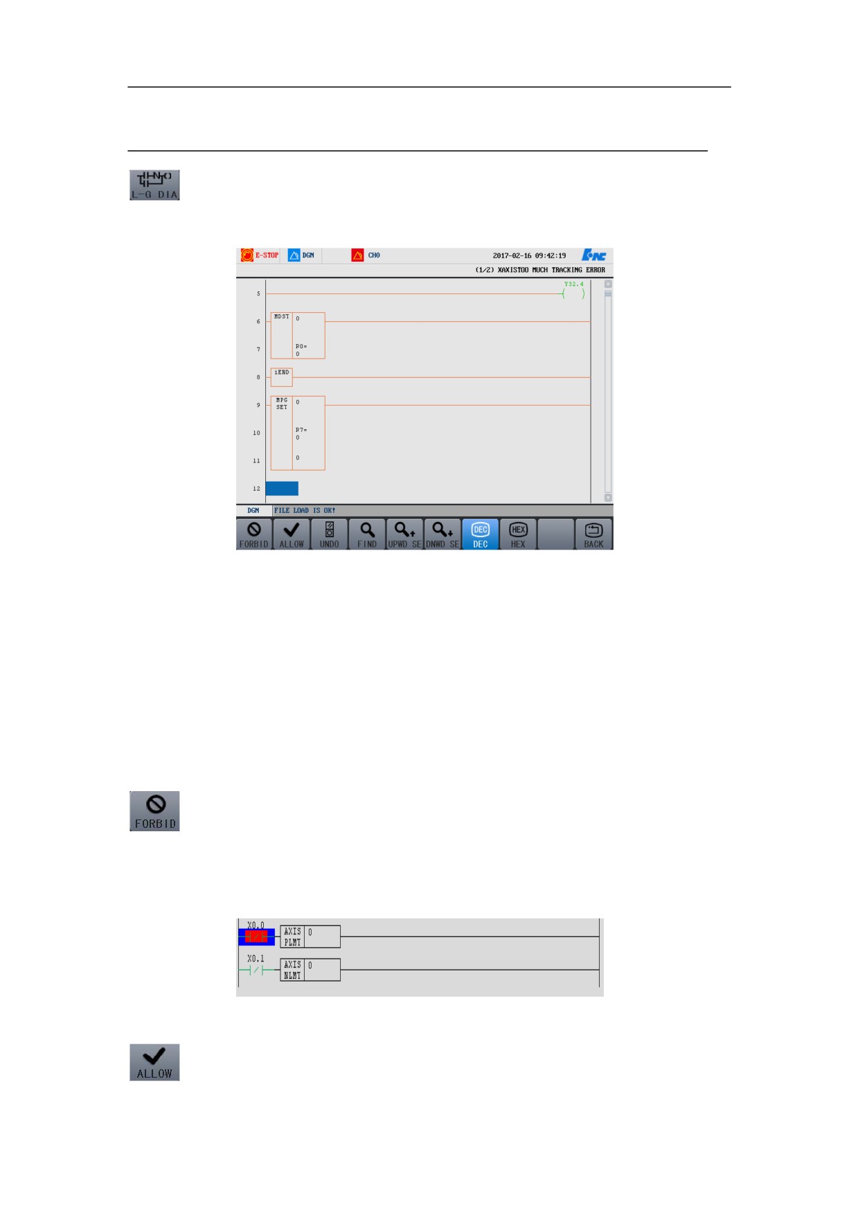
Press Ladder diagram diagnosis button to access the corresponding interface, as
seen in below figure. There are 6 buttons on this interface: Inhibit, Enable,
Redo, Decimal, Hexadecimal, and Return.
Press “Diagnosis→Ladder diagram monitoring→Ladder diagram diagnosis”, to
view the value of each variable. User can move the cursor up and down to view
variables. As seen above, the component turning green indicates that this
component is turned on or is valid, then user can use operations on the
component, such as inhibit, enable, redo and the like.
Inhibit function button. Move the cursor on the component, and press Inhibit
button, to shield the component. As shown in the below diagram, press Inhibit,
the component turns red, which indicated that the component is shielded. Press
Restore button to restore the function of the component, which will be covered
later.
245
HNC-8-PLC Programming specification
7. Operation monitoring and online modification of ladder diagram
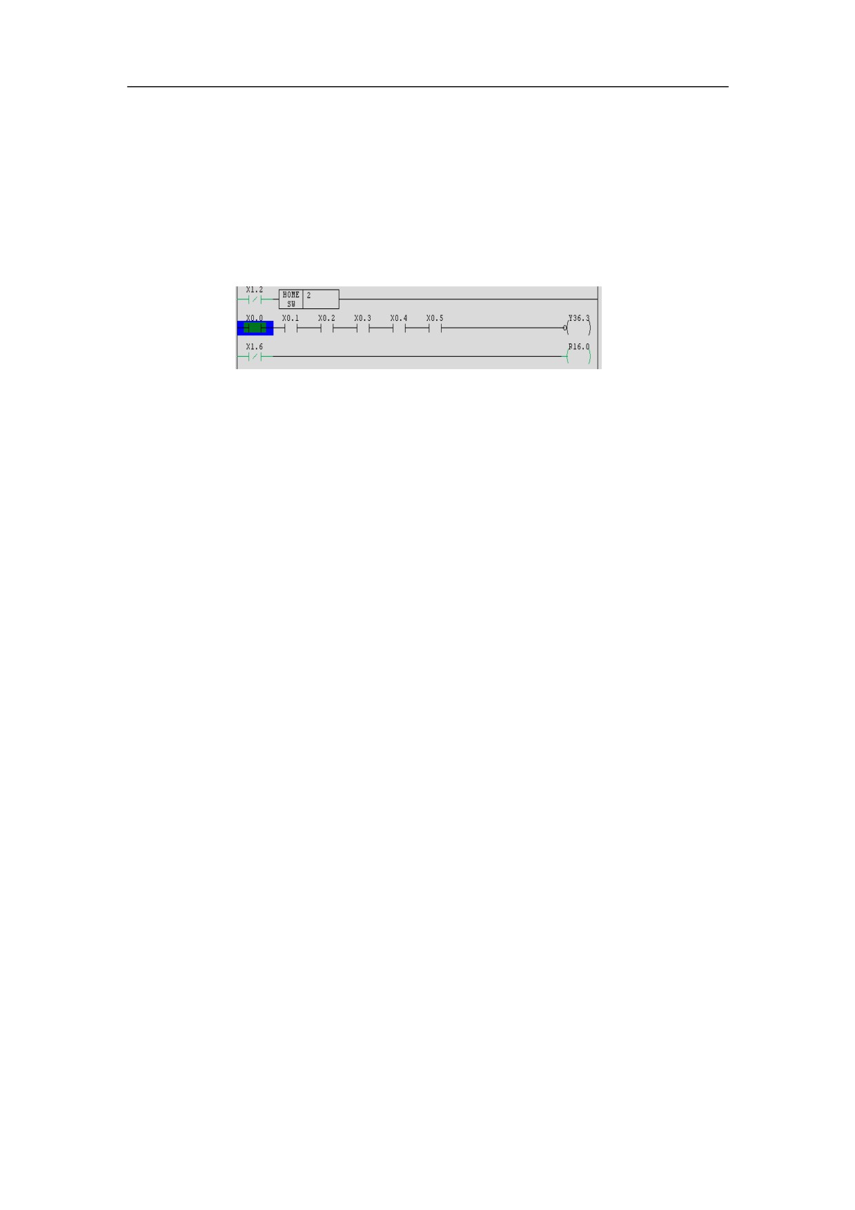
Enable function button. Move the cursor on the component, press Enable
button, and the component is enabled. As demonstrated below, the cursor has
been moved on the component, press Enable button, the component turns green,
which indicates that the component is enabled. In the below figure, X0.0 is
normally open. Move the cursor on X0.1, press Enable button, the component
turns green, and is switched off.
246
HNC-8-PLC Programming specification
7. Operation monitoring and online modification of ladder diagram
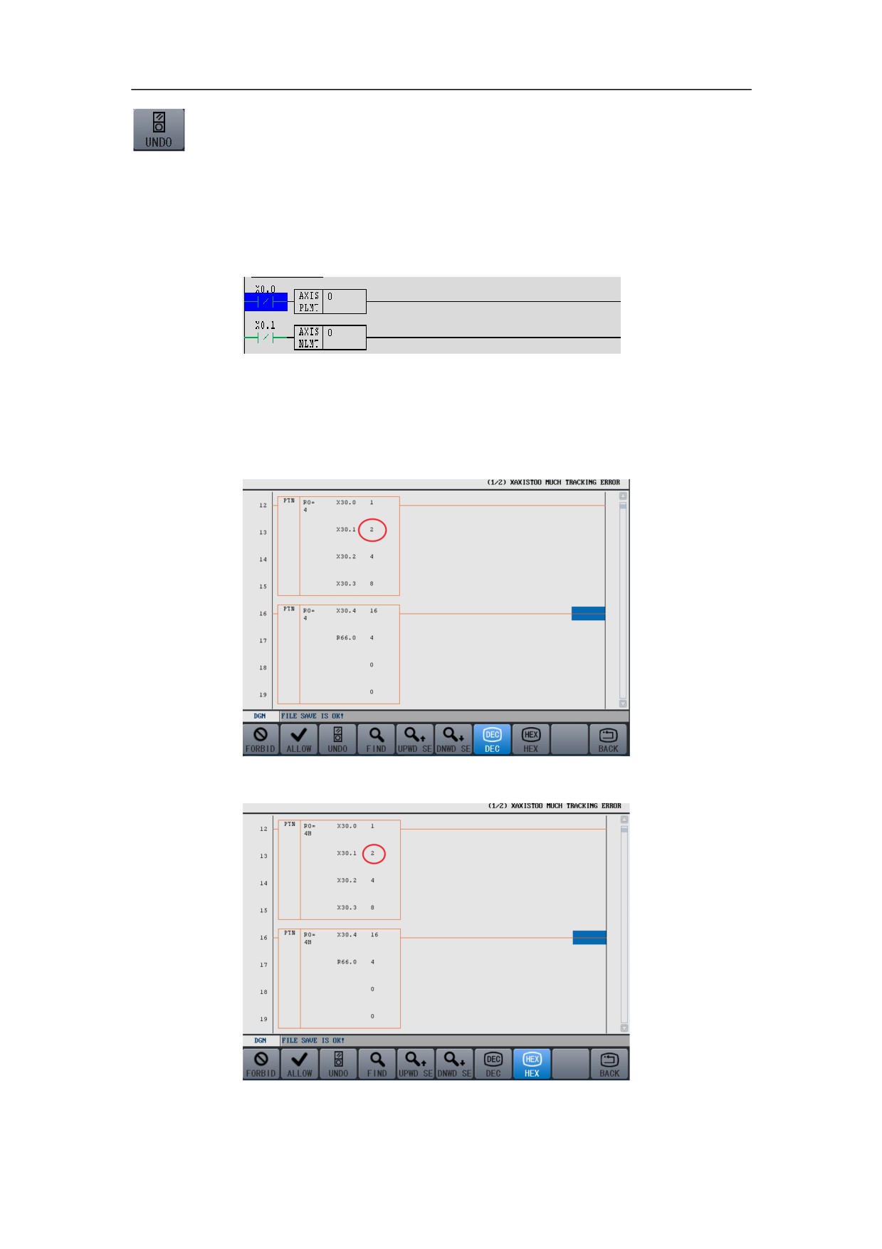
Restore function button. Move the cursor on the component, and press Restore,
to undo the shielding or enabling operations described above. Press this button
after Inhibit function is enabled, the red color on the component disappears,
which indicates that the function of component is restored, as shown in the
figure below.
The value in this system is by default in decimal, user can press the button
corresponding to “hexadecimal”, then the value is in hexadecimal, which is
shown as below:
¾ In decimal
¾ In hexadecimal
247

HNC-8-PLC Programming specification
7. Operation monitoring and online modification of ladder diagram
Return function button. Press this button to return to the interface of ladder
diagram monitoring, for performing other operations.
248
HNC-8-PLC Programming specification
7. Operation monitoring and online modification of ladder diagram
Search
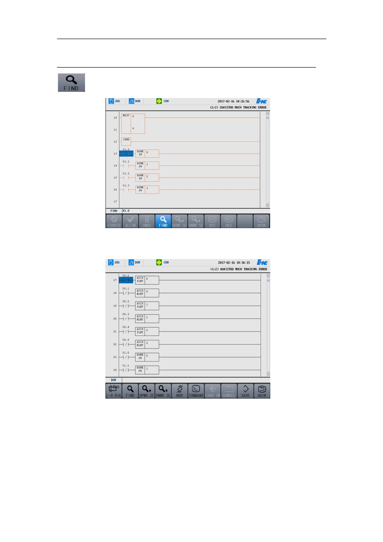
Press Search, then the operation interface as shown in the figure below appears,
where the component can be looked up.
For example, type X0.0, press “Enter”, the first X0.0 of the program under the
cursor line can be found. See illustration as below:
249
HNC-8-PLC Programming specification
7. Operation monitoring and online modification of ladder diagram
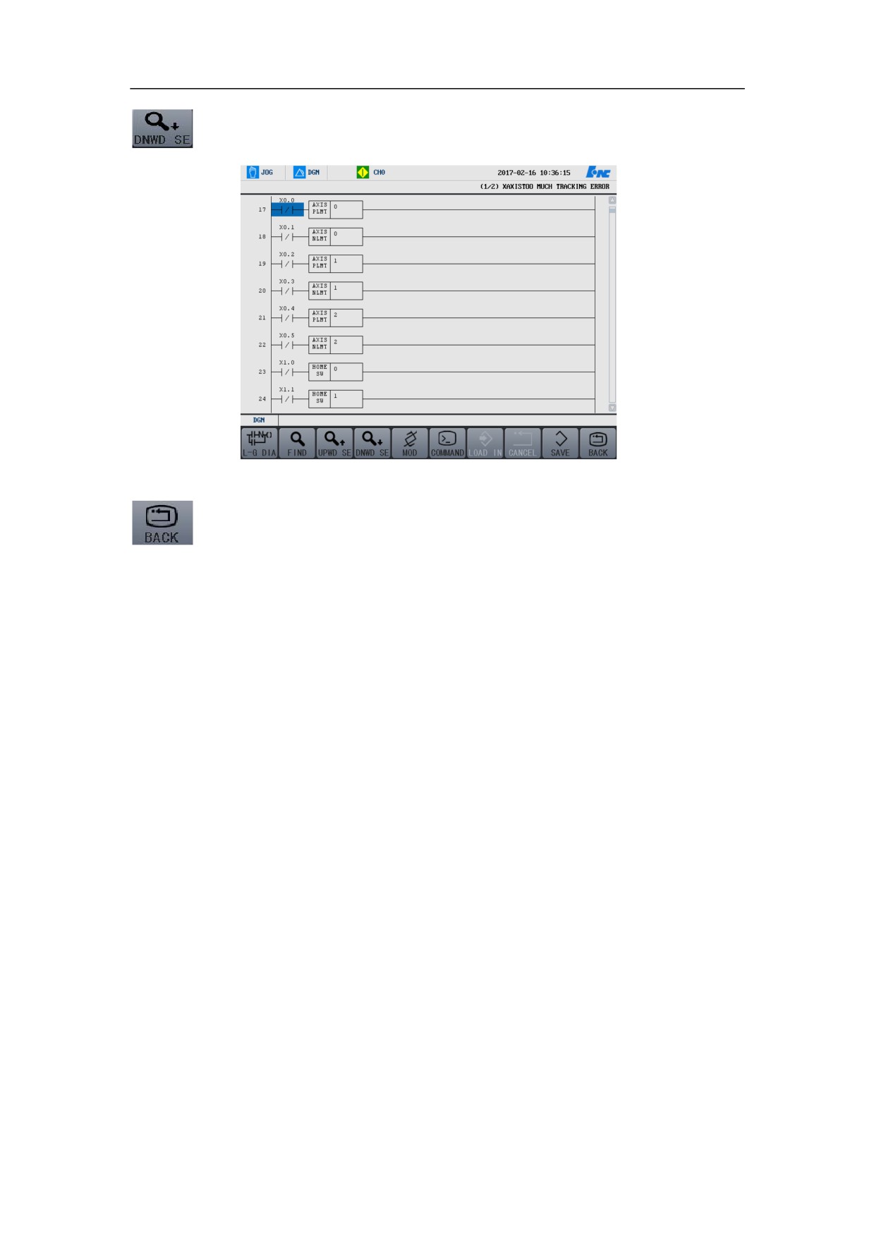
The found component is covered by blue curser. If you want to continue to
search, press “Continue”, then the next one can be found.
The functional button of Return. Press this button to return to the interface of
the ladder diagram monitoring.
250
HNC-8-PLC Programming specification
7. Operation monitoring and online modification of ladder diagram
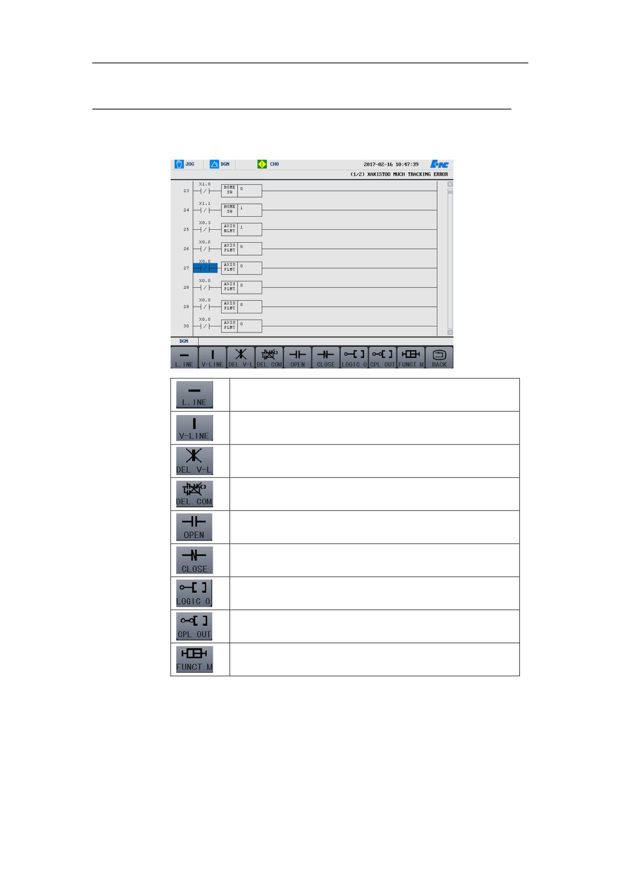
Change
User can press the corresponding functional button of “Change” menu, to
perform operations on the new component.
Straight line: insert a straight line
Vertical line: insert a vertical line
Delete vertical line: Delete a vertical line
Delete component: delete a component
Normal open: insert a normal-open contact
Normal closed: insert a normal-closed contact
Logical output: insert an output
Inverted output: insert an inverted output
Functional module: insert a function (user can press the initial word of the
component, to select it)
251
HNC-8-PLC Programming specification
7. Operation monitoring and online modification of ladder diagram
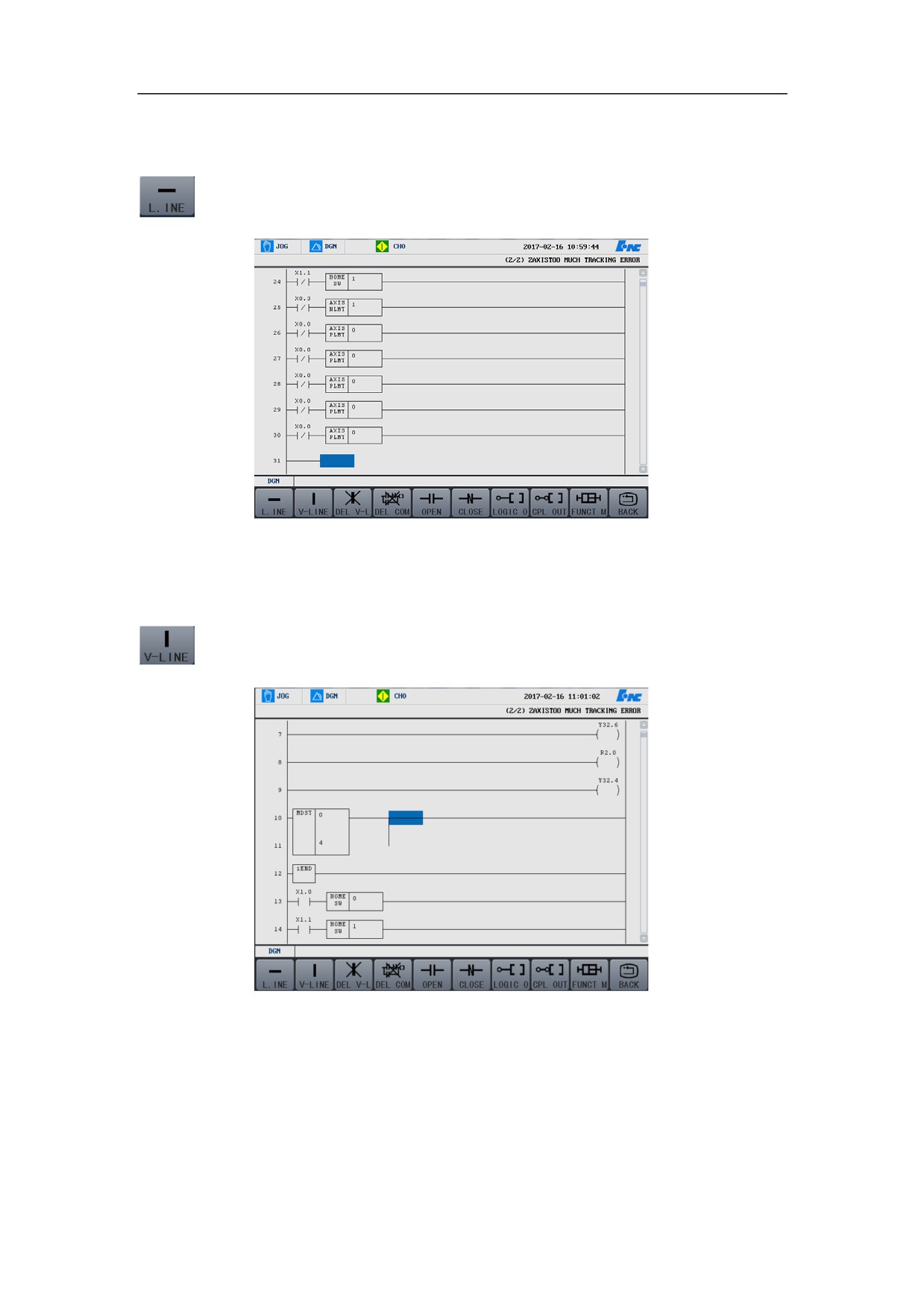
Insert Straight Line
Press the functional button of “Straight Line” to insert a straight line in the
ladder diagram, see as below:
Insert Vertical Line
Press the functional button of “Vertical line” to insert a vertical line after the
cursor, as shown in the figure below:
252
HNC-8-PLC Programming specification
7. Operation monitoring and online modification of ladder diagram
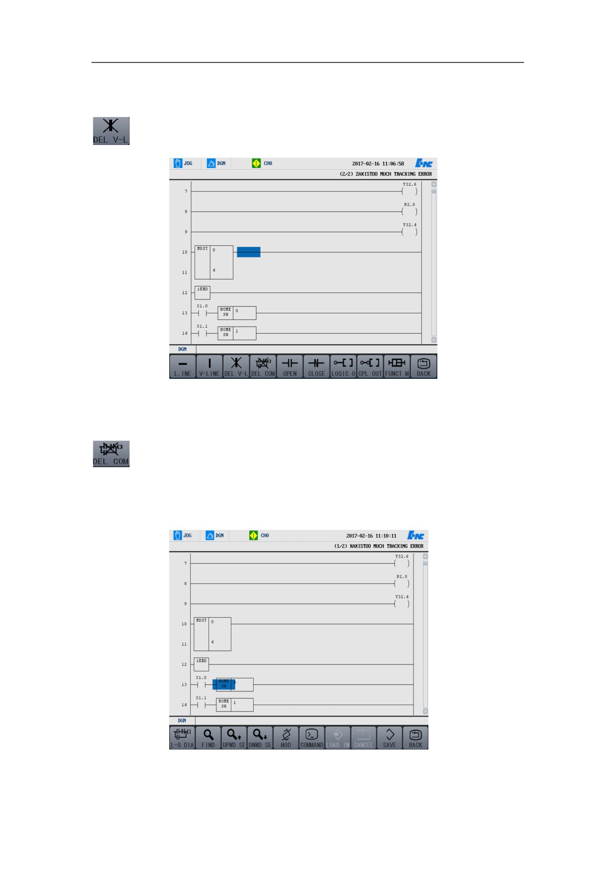
Delete Vertical Line
Press the functional button of “Delete Vertical Line” to delete the vertical line
after the cursor, as demonstrated below:
Delete Component
Move the cursor on the component to be deleted, press the functional button of
“Delete Component” to delete the component in the ladder diagram.
¾ Before the deletion
253
HNC-8-PLC Programming specification
7. Operation monitoring and online modification of ladder diagram
¾ After the deletion
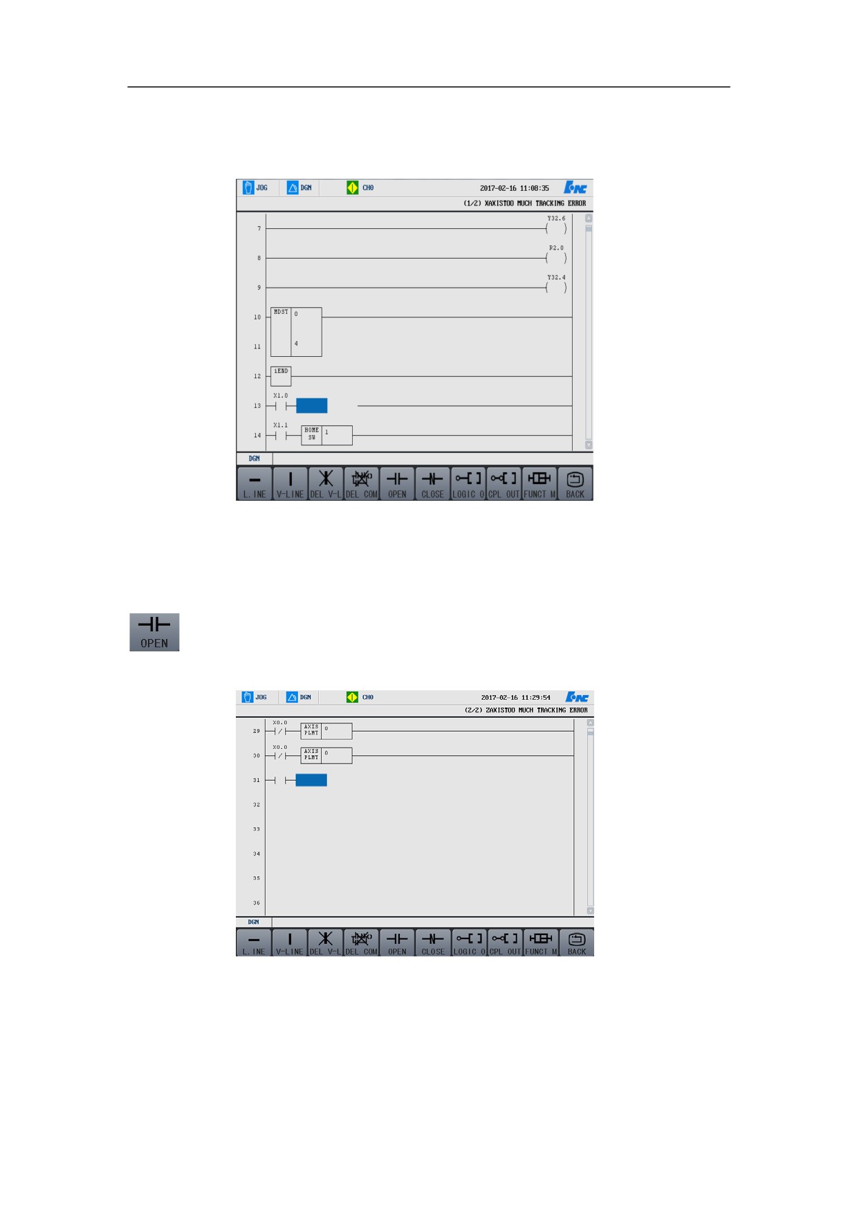
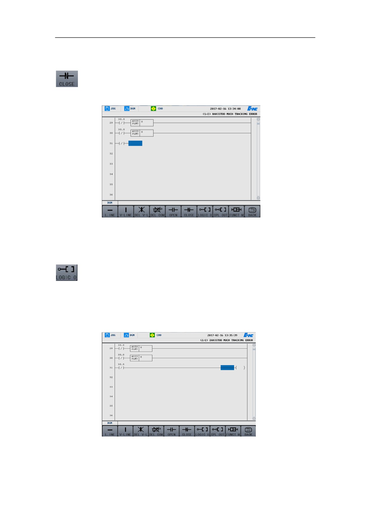
Normal Open
Move the cursor to the position where the normal-open contact is to be inserted,
press the functional button of “Normal open” to insert the normal-open contact
at the specified position.
254
HNC-8-PLC Programming specification
7. Operation monitoring and online modification of ladder diagram
Normal Closed
Move the cursor to the position where the normal-closed contact is to be
inserted, press the functional button of
“Normal close” to insert the
“normal-closed” contact at the specified position. as shown in the figure below:
Logical Output
Move the cursor to the position where the logical output needs to be inserted,
press the functional button of “Logical output” to insert the logical output at the
specified position in the ladder diagram, as shown in the figure below. It is
important to note that pre can be added to the logical output, but post cannot.
Refer to the section of programming for details.
255
HNC-8-PLC Programming specification
7. Operation monitoring and online modification of ladder diagram
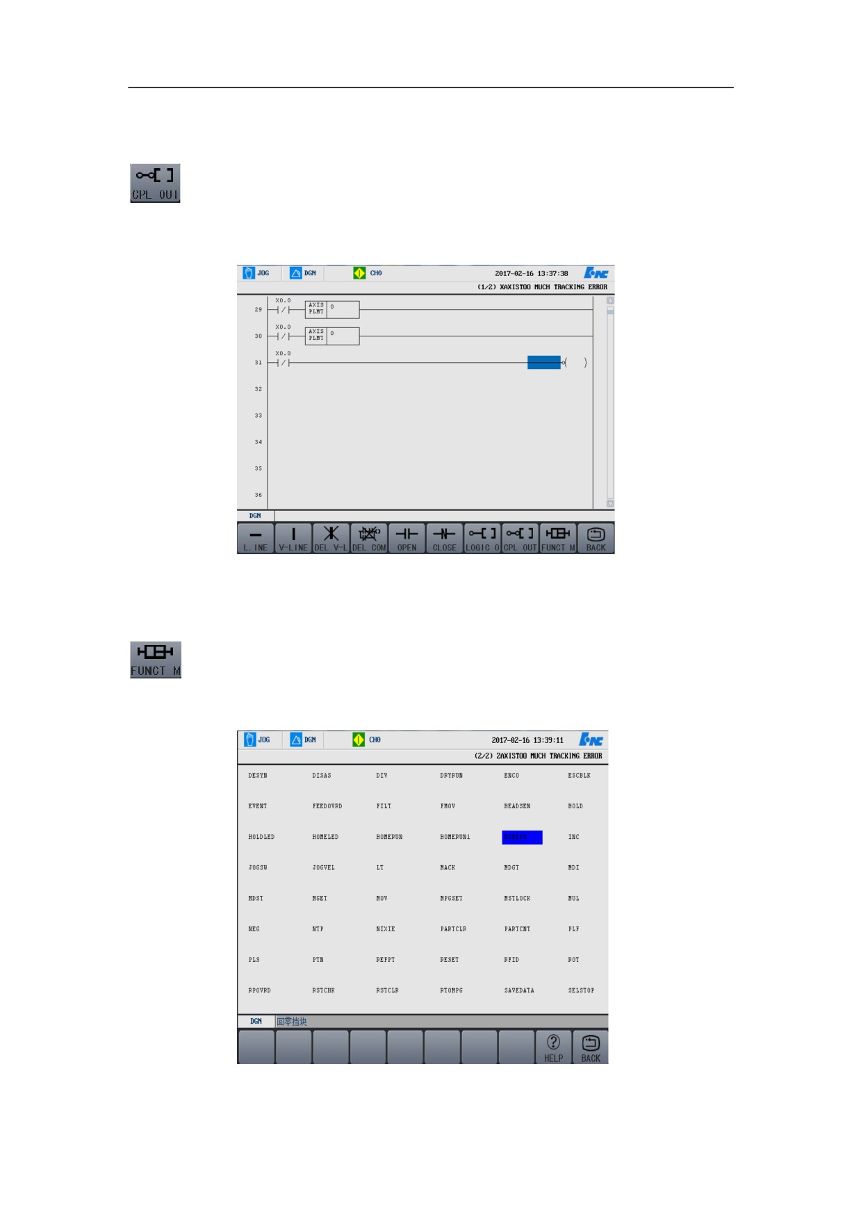
Inverted Output
Move the cursor to the position where the inverted output needs to be inserted,
press the functional button “Inverted output” to insert the inverted output at the
specified position in the ladder diagram, which is illustrated by the following
figure.
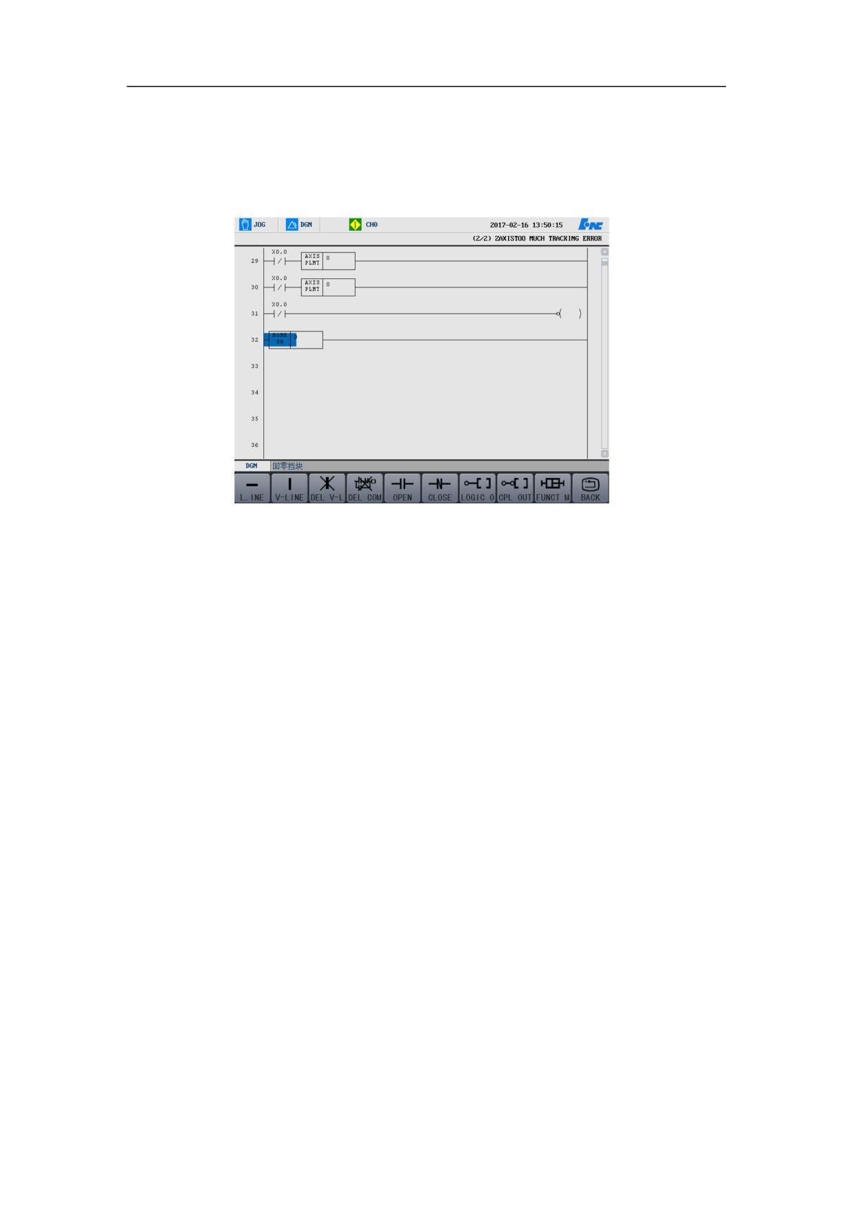
Functional Module
Press the functional module button to access the operation interface shown as
below figure, and select the functional module needed.
256
HNC-8-PLC Programming specification
7. Operation monitoring and online modification of ladder diagram
Then hit Enter to enter the selected functional module into the ladder diagram.
User can press the initial word of the component to select the relevant
component.
Press functional module button again to return to the interface of operation
modification.
Return
Press “Return” to return to the previous operation interface.
257
HNC-8-PLC Programming specification
7. Operation monitoring and online modification of ladder diagram
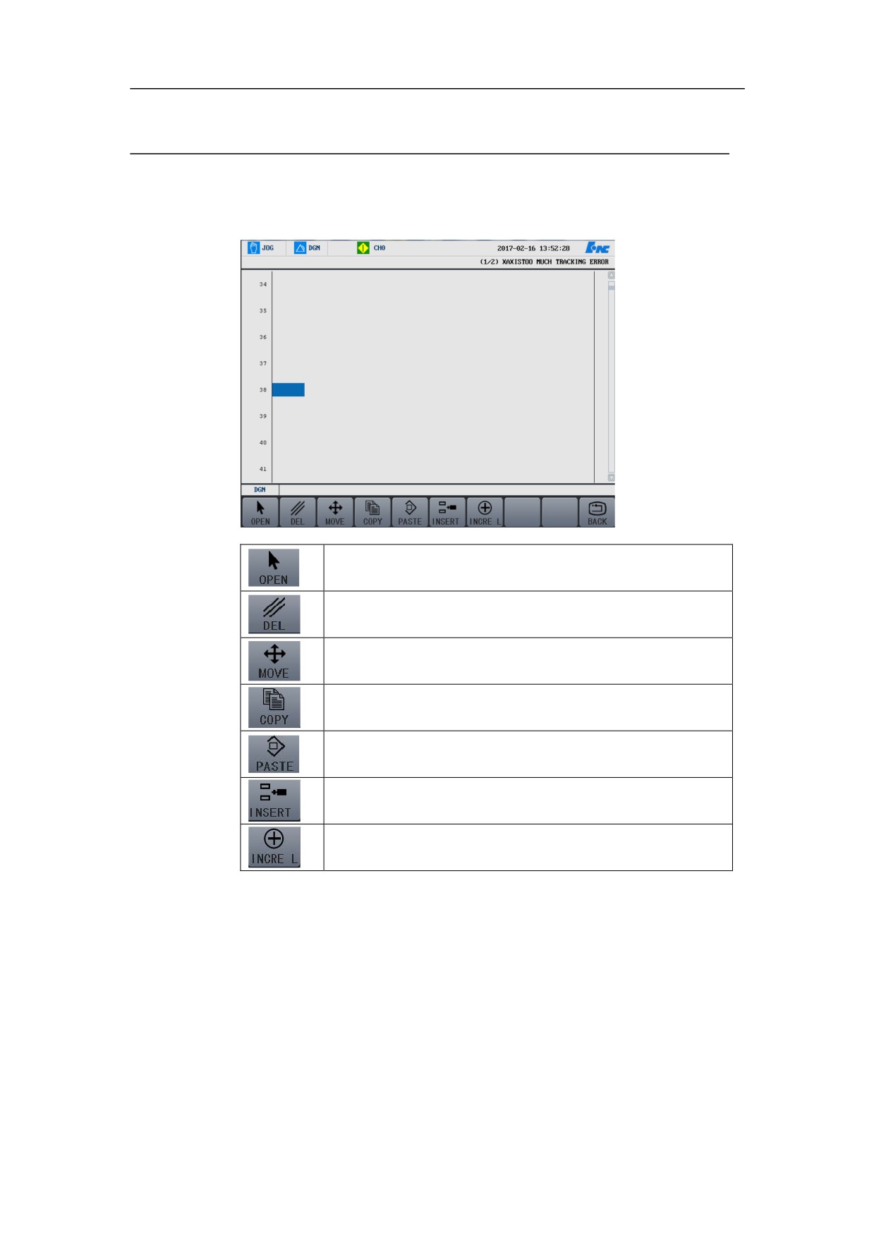
Command
User can press the buttons listed in the below table to edit the ladder diagram.
Select: select the cursor line
Delete: delete the cursor line
Move: move the selected component
Copy: copy the selected component
Paste: paste the selected component
Insert row: insert a line before the cursor line
Add row: insert a line after the cursor line
258
HNC-8-PLC Programming specification
7. Operation monitoring and online modification of ladder diagram
Select
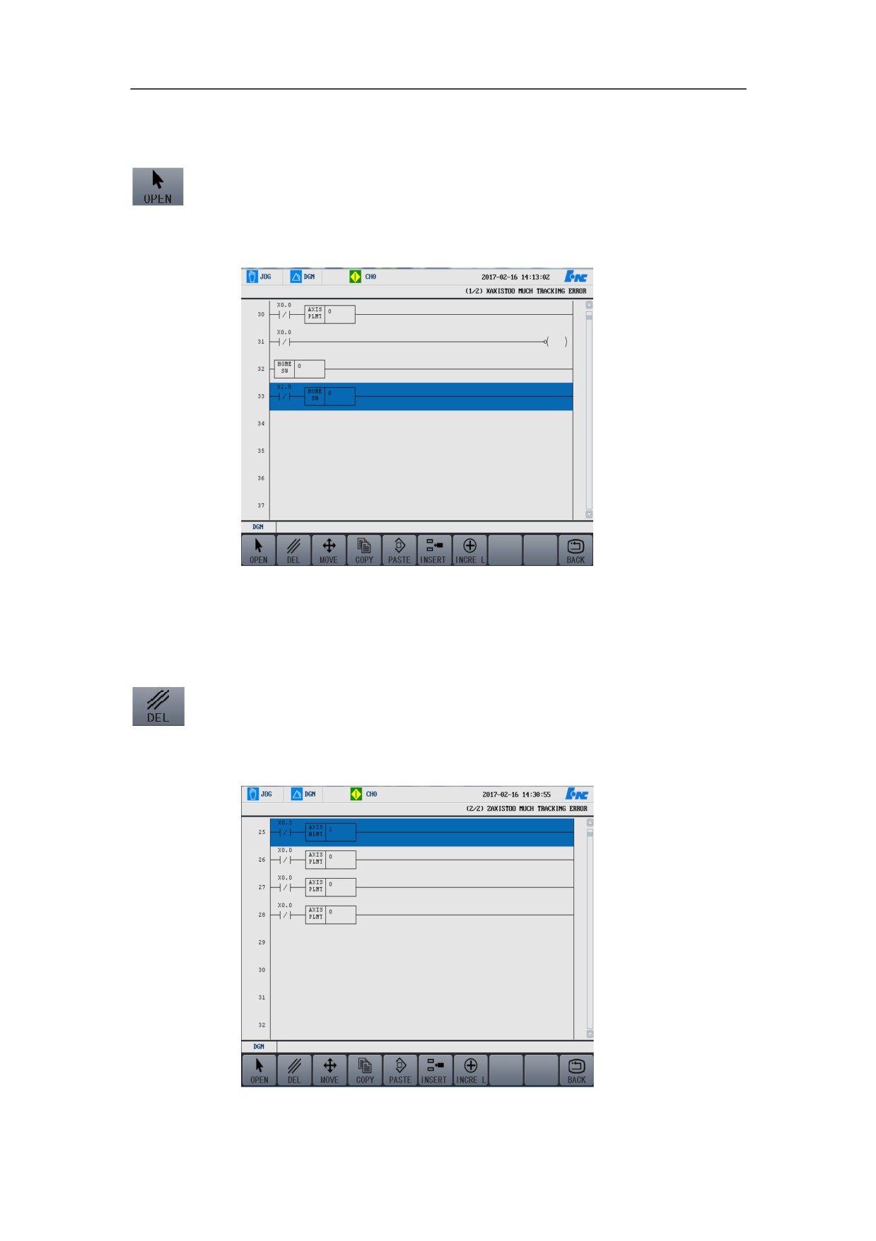
Move the cursor to the line that you want to select, press the functional button of
“Select”, the selected line turns blue, and then press “Select” button again to
select the next line of the current line. It is illustrated by the following figure.
You can perform the operations such as delete, after selecting the line you want.
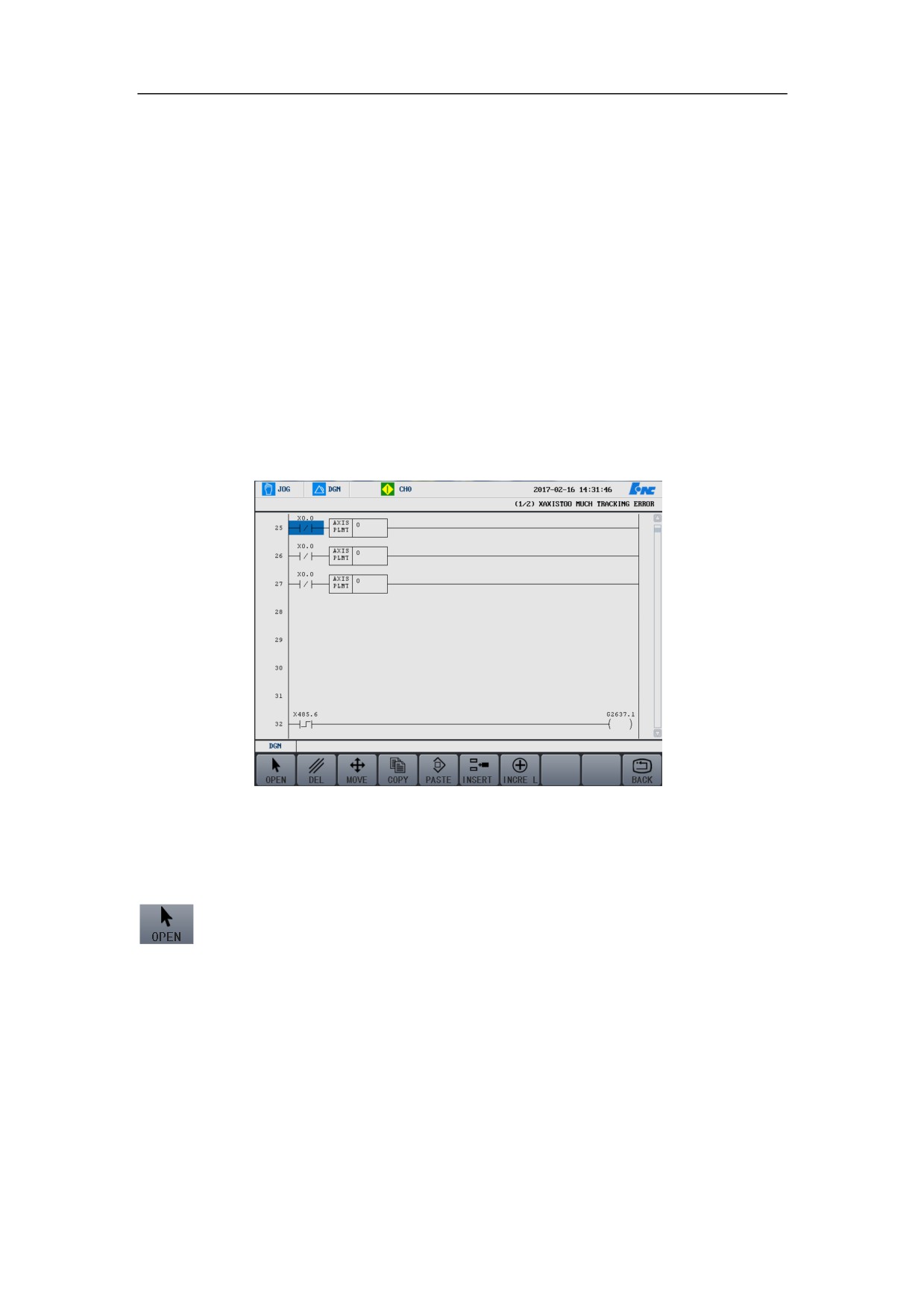
Delete
Move the cursor to the line to be deleted, press “Select” button, the line turns
blue, then press “Delete” to delete this line.
¾ Before the deletion
259
HNC-8-PLC Programming specification
7. Operation monitoring and online modification of ladder diagram
¾ After the deletion
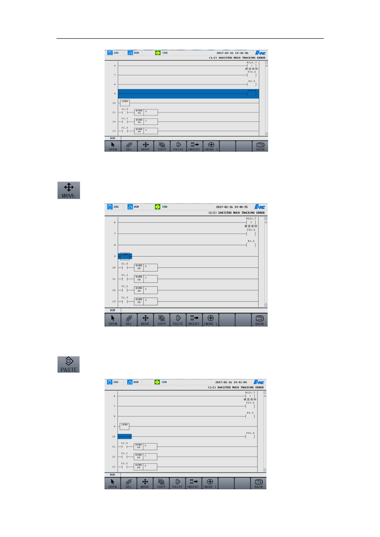
Move
First move the cursor to the line to be moved, then press “Select” button, this
line turns blue.
260
HNC-8-PLC Programming specification
7. Operation monitoring and online modification of ladder diagram
Press the functional button “Move” to access the interface which is shown in the
below figure, and the selected line disappears.
Move the cursor to the target line, and press “Paste” to move the selected line to
the target line.
261
HNC-8-PLC Programming specification
7. Operation monitoring and online modification of ladder diagram
262
HNC-8-PLC Programming specification
7. Operation monitoring and online modification of ladder diagram
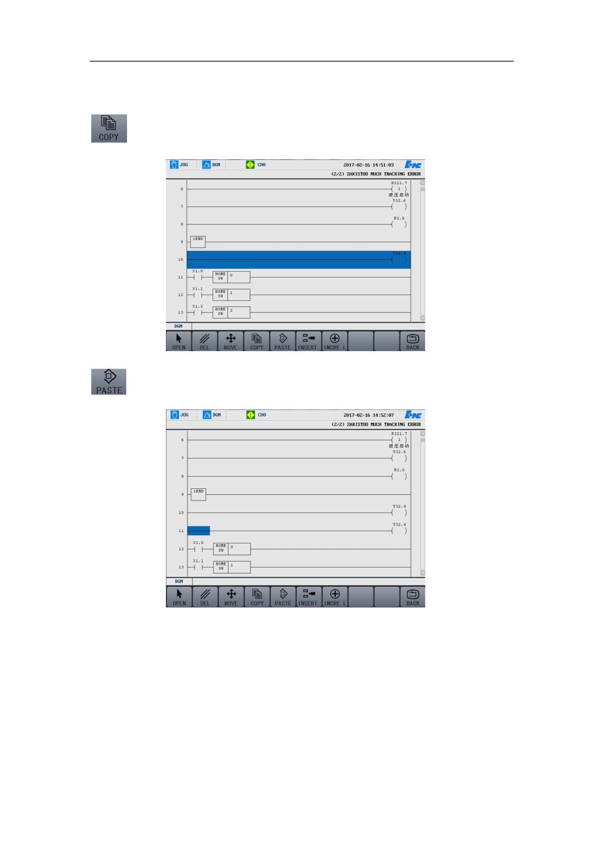
Copy
Move the cursor to the position of the line that needs to be copied, then press the
functional buttons of “Select” and “Copy”. See as below:
Move the cursor to the target line, and press the functional button of “Paste” to
paste the copied line.
263
HNC-8-PLC Programming specification
7. Operation monitoring and online modification of ladder diagram
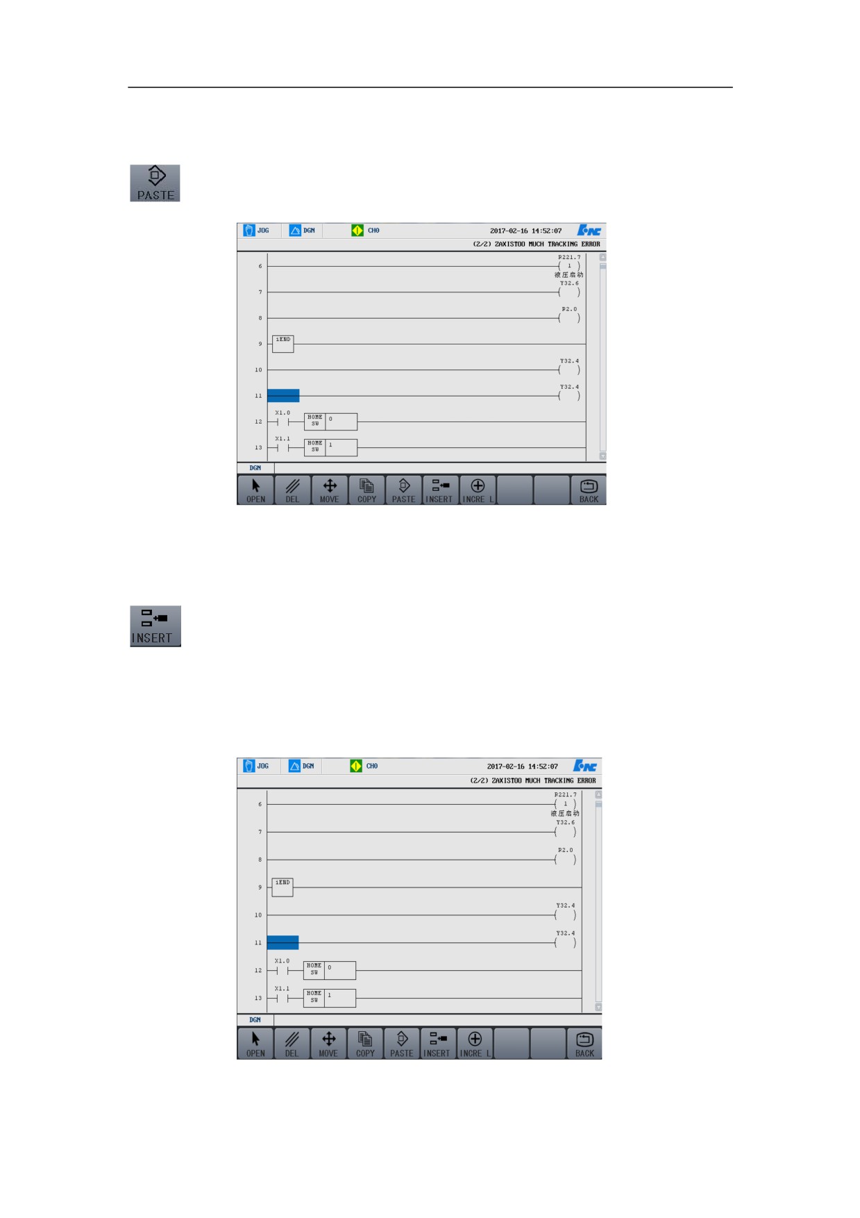
Paste
The functional button of “Paste” has been applied in section 7.4.3 and 7.4.4.
Refer to the two sections for the detailed operations.
Insert Line
As shown in the figure below, move the cursor to the next line of the line to be
inserted, press the functional button of “Insert line”, then the line is inserted.
Note that the line is generally inserted above the cursor line.
¾ Before inserting,
264