HNC-8 Numerical Control System Software. Maual of PLC Programming (V1.24) - page 10
HNC-8-PLC Programming specification
7. Operation monitoring and online modification of ladder diagram
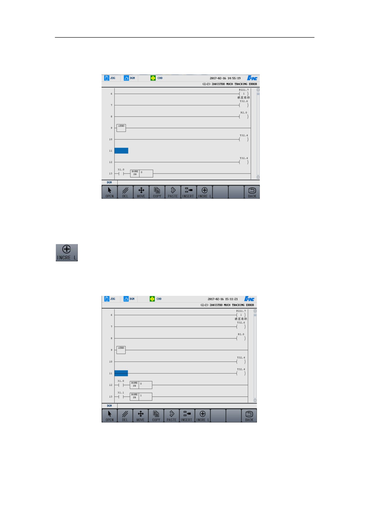
¾ After inserting,
Add Line
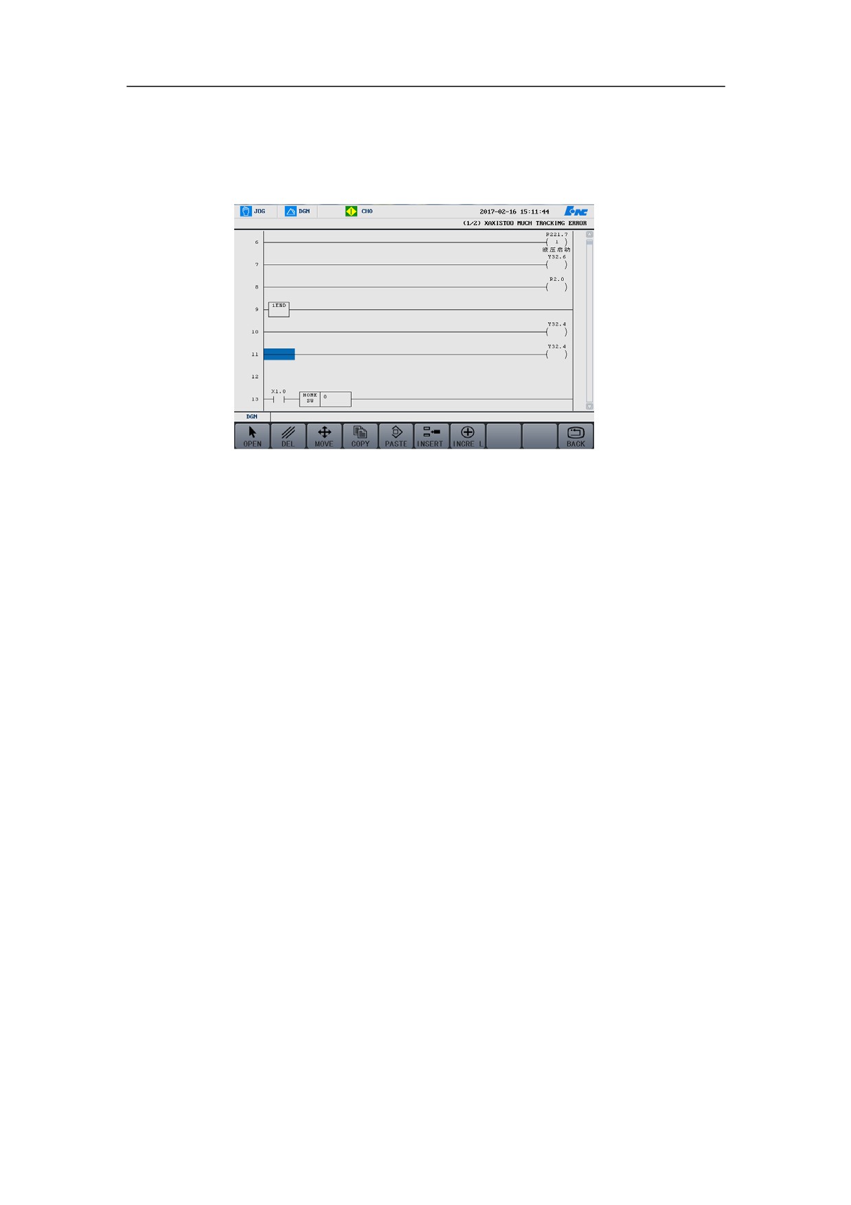
The functional button of “Insert line” is in contrast to “add line” where the line is
added below the cursor line, as shown in the figure below, press the functional
button of Add line, then a new line is added below the cursor line.
¾ Before adding
265
HNC-8-PLC Programming specification
7. Operation monitoring and online modification of ladder diagram
¾ After adding
Return
Press the functional button of Return to back to the previous interface.
266

HNC-8-PLC Programming specification
7. Operation monitoring and online modification of ladder diagram
Load
Edit and check the ladder diagram, press the functional button of Load, then the
system loads the current ladder diagram.
267

HNC-8-PLC Programming specification
7. Operation monitoring and online modification of ladder diagram
Discard
If you want to re-edit the edited ladder diagram, press the functional button of
“Discard” to cancel the operations that you have edited to the diagram.
268

HNC-8-PLC Programming specification
7. Operation monitoring and online modification of ladder diagram
Save
After the ladder diagram is saved, press this button, to save the ladder diagram
edit operations.
269
HNC-8-PLC Programming specification
7. Operation monitoring and online modification of ladder diagram
Return
Press the functional button of Return, to return to the diagnosis interface.
270
HNC-8-PLC Programming specification
8 . PLC Development environment description
Instruction
on PLC Development
Environment
This chapter includes:
7.1 Overview
7.2 Installation of Development Environment
7.3 Development Environment Interface
7.4 Development Environment Operation
271
HNC-8-PLC Programming specification
8 . PLC Development environment description
Overview
HNC-LADDER-WIN Numerical Ladder Diagram Programming Software is a
latest software of PLC program development environment for Series 8 NC
system. This software runs on Windows XP operating system, and can easily set
up ladder diagrams by visual graph programming. It is compatible with various
of PLS languages that are compliant to IEC61131-3 international standard, and is
a simple, efficient, and reliable PLC development tool.
272
HNC-8-PLC Programming specification
8 . PLC Development environment description
Installation of Development Environment
Using the example of installing from CD on Chinese Windows XP, this section
explains how to install the ladder diagram development environment.
(1) Boot into Chinese WindowsXP.
(2) Place the disk of ladder diagram development environment in the CD-ROM
drive.
(3) Double click Setup.exe file under the directory of Huazhong NC ladder
diagram, the installation program may run automatically, and then the
installation wizard appears.
(4) The greeting window appears after the installation wizard interface.
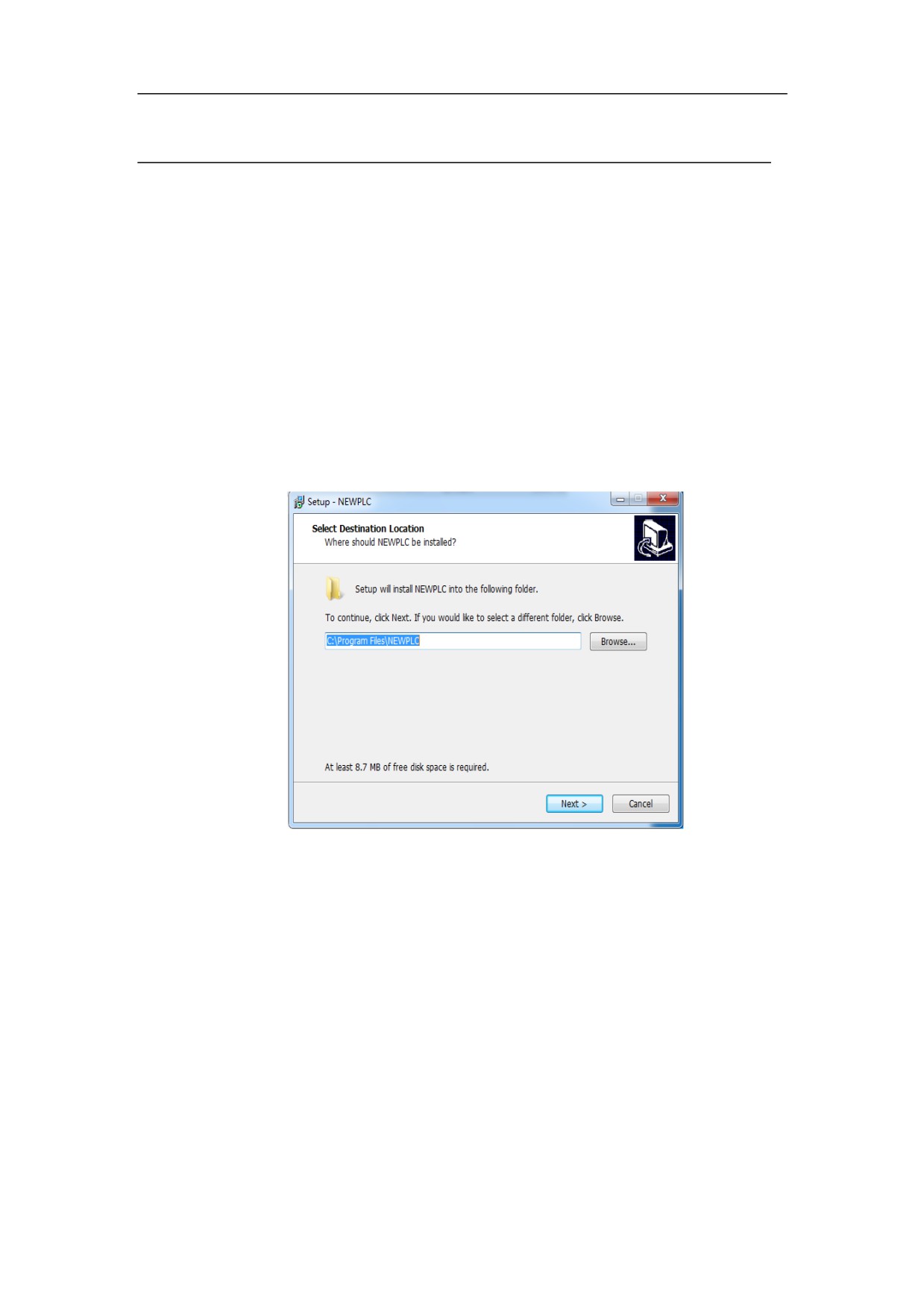
(5) Click “Next (N)”, and the selection dialog displays on the screen.
273
HNC-8-PLC Programming specification
8 . PLC Development environment description
(6) After doing some necessary modifications to your installation path on the
selection dialog, click “Next(N)”.
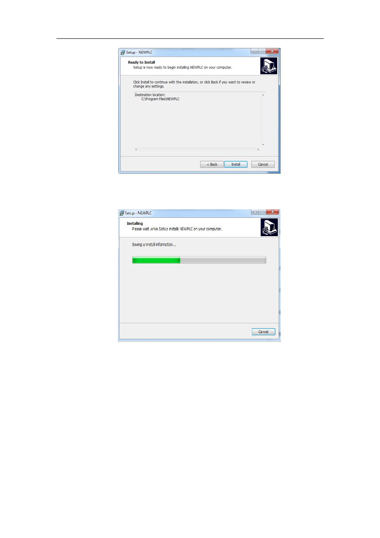
(7) Then the formal installation starts, with the above displaying on the screen.
274
HNC-8-PLC Programming specification
8 . PLC Development environment description
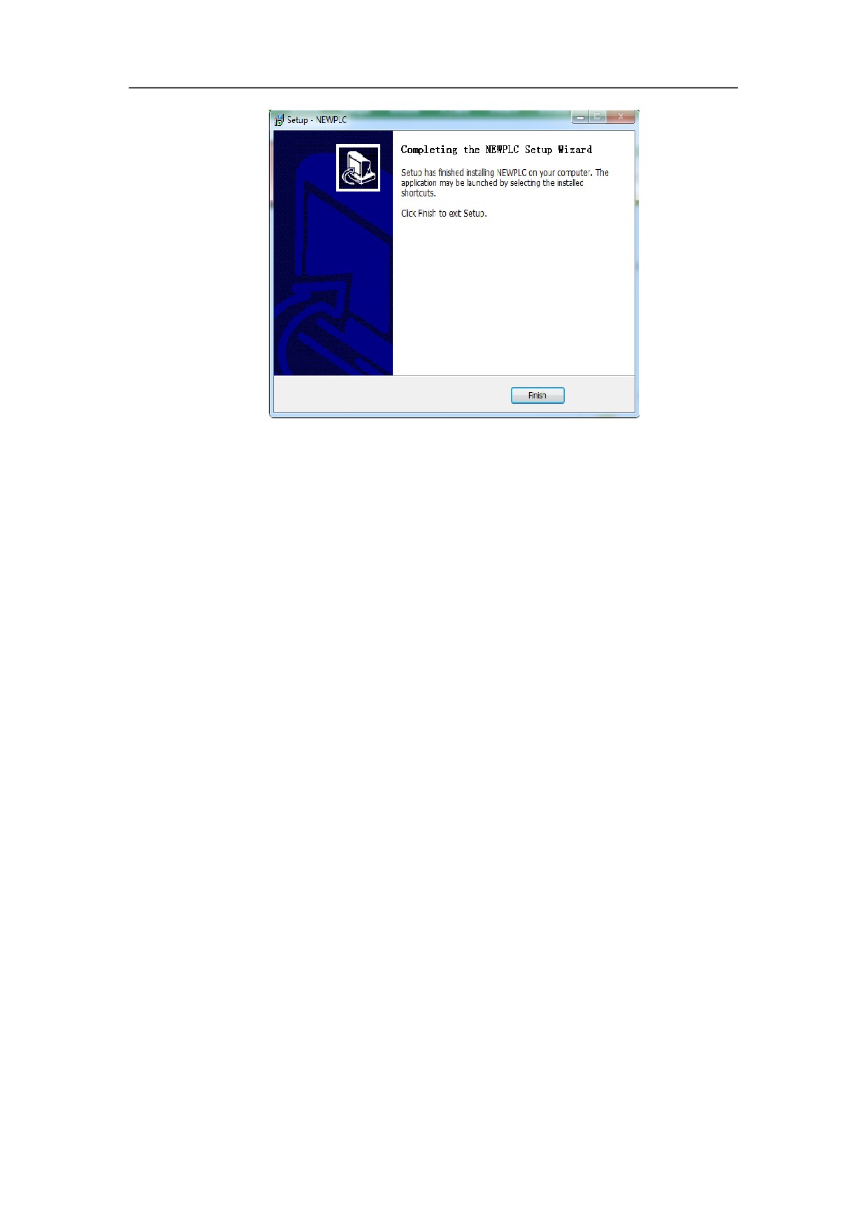
(8) After the installation is complete, the installation complete interface
appears.
275

HNC-8-PLC Programming specification
8 . PLC Development environment description
Development Environment Interface
Development Environment of ladder diagram is divided into four parts: menu,
ladder diagram, statement list, and symbol table.
Menu
The bar at the top of the development environment is called menu, where every
pulldown menus of ladder diagram interface are listed. Clicking a menu item
shows the command options in the pulldown menu. Click a command to handle
relevant operation.
There are six items in the development environment menu: file, view, tool,
window, and help, which are discussed in the following:
File
The “File” menu contains the command items working on files, which mainly
provide operations on files of ladder diagram with user.
New
This item is for creating a new project.
Open
This item is to open an existing dft file.
Save
This item is for saving files of current window as dft files.
Save as
The function of this item likes “save ladder diagram” item,
which is to save open files, and the difference is that this
item is to save the open files with new names.
Close
This item is for closing current ladder diagram interface.
Load dit file
This item is for opening existing dit files.
Print
This item is for printing current window contents.
Print preview
This item is for previewing print effect.
Print setup
Parameter This item is to set printing parameters.
Exit
When you select this item, the program exits.
Edit
276
HNC-8-PLC Programming specification
8 . PLC Development environment description
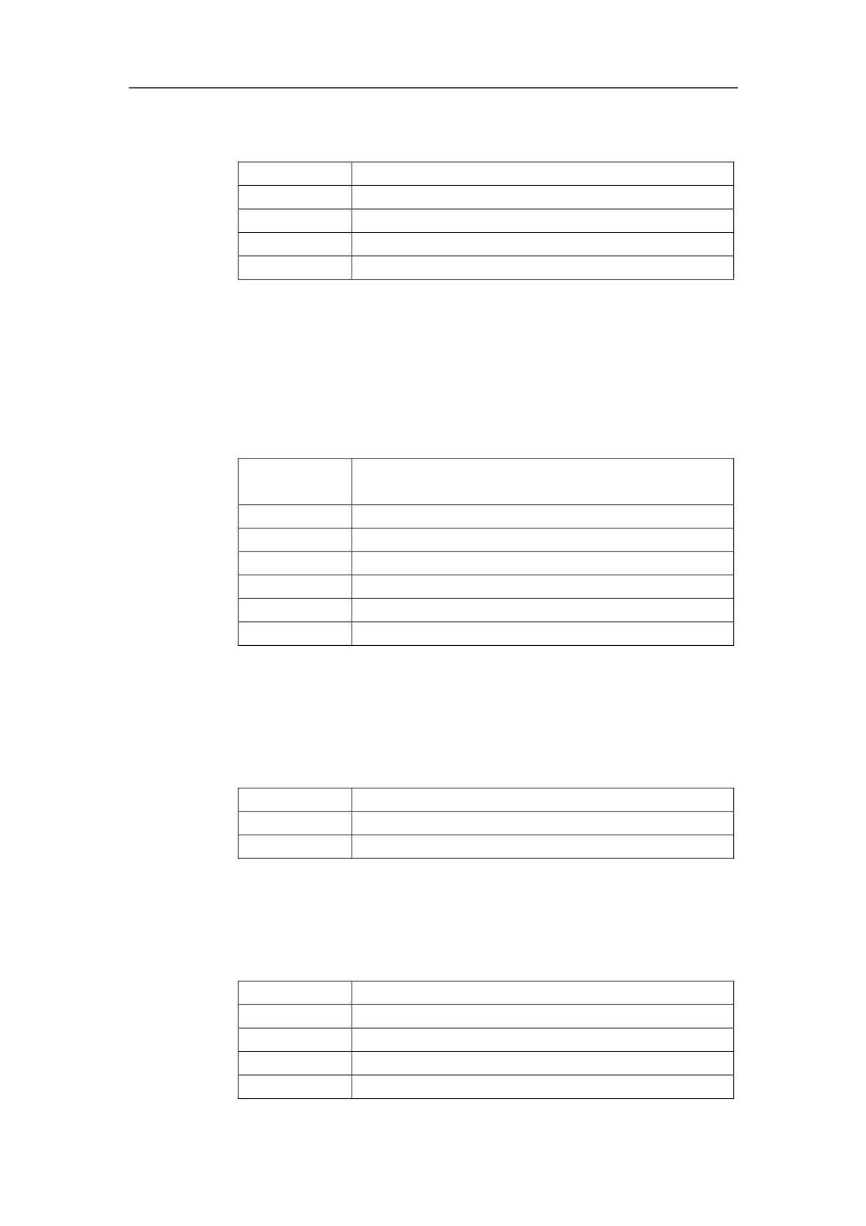
The “Edit” menu contains rapid operations of copy, paste and the like, of which
the purpose is to improve the efficiency of writing the ladder diagram.
Cut
Cut string and element.
Copy
Copy string and element
Paste
Paste string and element
Insert row
Insert a row at the current cursor location
Delete row
Delete the row which the current cursor locates.
View
“View” menu is to control the subwindow displaying in the main window.
Ladder
To open (close) ladder diagram view.
diagram
Statement list
To open (close) statement list view.
Symbol list
To open (close) symbol list view.
Primitive tree
To open (close) primitive tree view on the left.
Message box
To open (close) message box at the bottom.
Toolbar
To open (close) toolbar.
Status bar
To open (close) status bar.
Tool
The function of “Tool” menu is to find/replace.
Search
To search the specified string.
Search next
To continue to search the specified string.
Replace
To replace the specified string.
Window
“Window” menu is used to open each window.
Overlap
To arrange subwindows in overlap.
Tile
To arrange subwindows in tiling.
REG
To display symbol list window.
STL
To display statement list window.
LADDER
To display ladder diagram window.
277
HNC-8-PLC Programming specification
8 . PLC Development environment description
Help
About NEWPLC: to display the software version.
278
HNC-8-PLC Programming specification
8 . PLC Development environment description
Ladder Diagram Interface
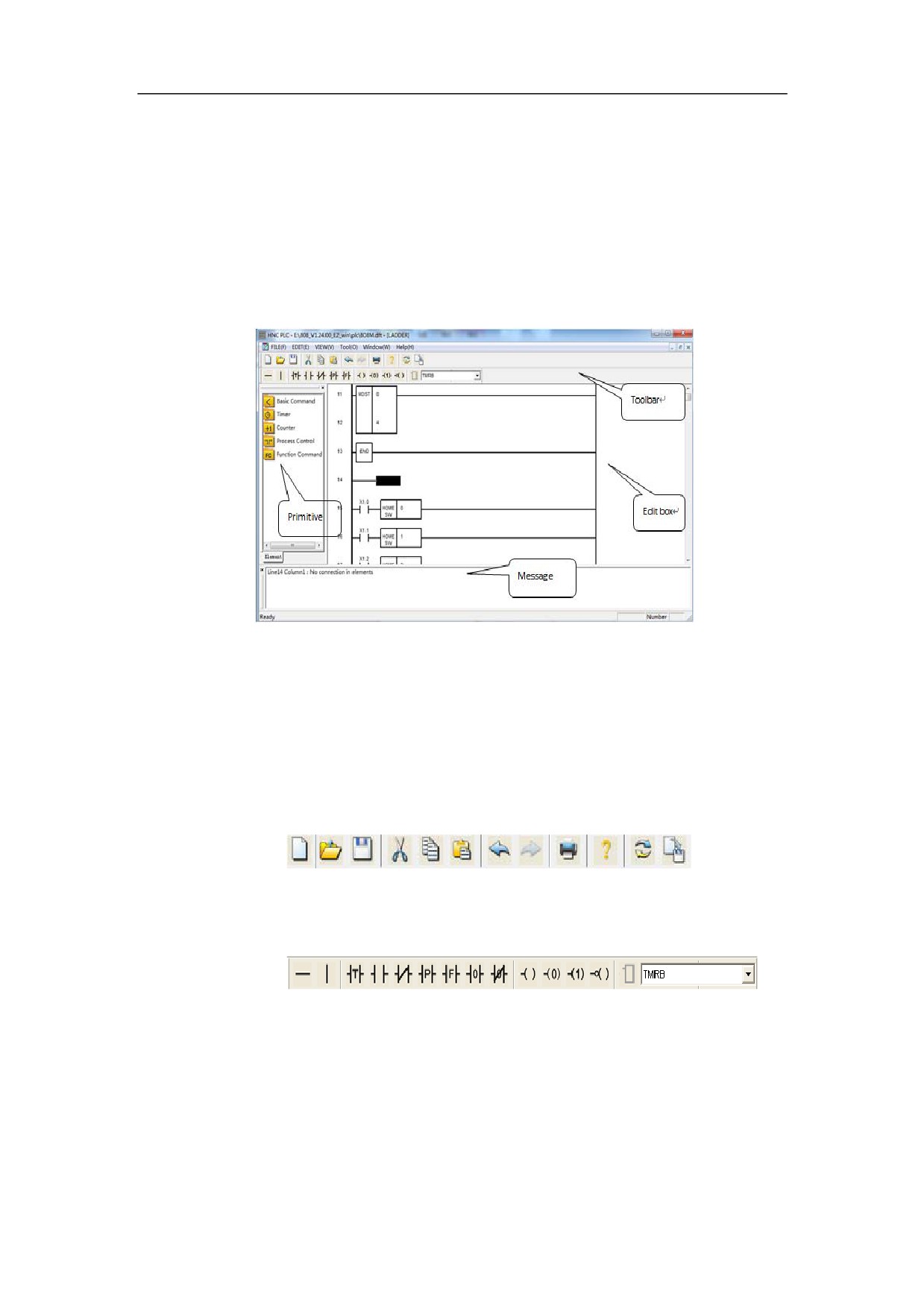
Four parts including toolbar, primitive tree, edit window, and message box are in
the ladder diagram window.
Toolbar and primitive tree can dock freely, that means, they can be put on any of
the four side walls of the main window. Toolbar can be located anywhere on the
desktop.
Toolbar
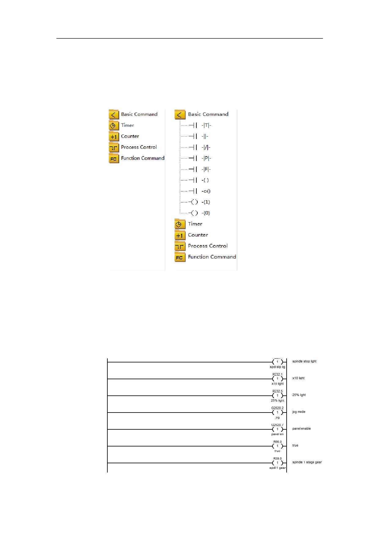
There are two toolbars including action bar and component bar, in the ladder
diagram interface.
(1) Action bar is used to manipulate new files quickly, such as zooming, undo,
redo, and so on.
(2) Component bar is used to fast add the basic input/output cell and the
selection function module.
279
HNC-8-PLC Programming specification
8 . PLC Development environment description
Primitive Tree
Primitive tree is used for selection function module. Double-clicking the icon
can expand and collapse the instruction tree. Select the instruction icon needed
from the instruction tree.
Edit Window
Edit
Edit window is for displaying and editing the ladder diagram. The area between
the left busbar and the right busbar is the editing domain of the ladder diagram,
the row number you are currently editing displays on the left of the left busbar,
and the comments to the meaning of output status for the current line displays on
the right of the right busbar.
280
HNC-8-PLC Programming specification
8 . PLC Development environment description
Message Box
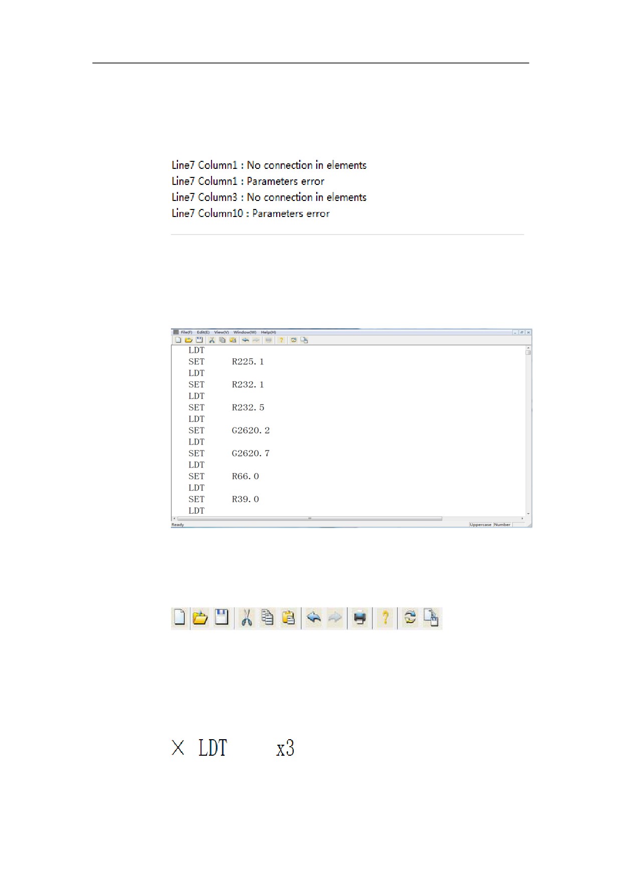
While the ladder diagram is being compiling, the statement error and syntax
error which can be recognized, may appear in the message box.
Statement List Interface
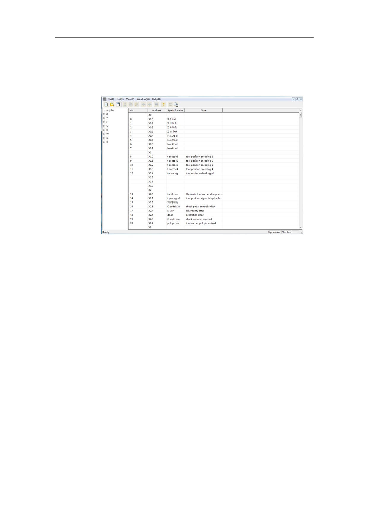
Toolbar and edit window are in the statement list interface.
Toolbar
An action tool is in the statement list interface.
Edit Window
Edit window is for displaying and editing statement list, and can judge the
current row when the statement list is being editing.
281
HNC-8-PLC Programming specification
8 . PLC Development environment description
Symbol List Interface
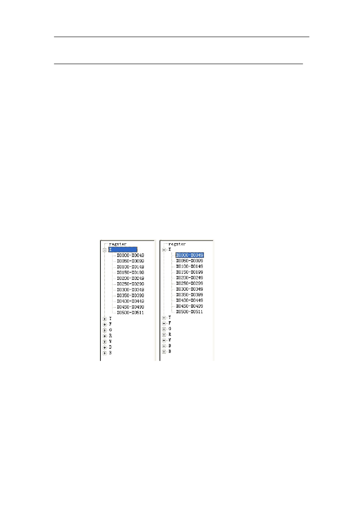
Symbol names and comments of relevant addresses can be defined in symbol list
interface.
Selection box for register is on the left of edit window of the symbol list, and
edit box for register is on the right.
The edit box for register includes number, address, symbol name and comments.
z
Number: automatically generate the number of the current symbol name in
all the symbol names.
z
Address: the specified address.
z
Symbol name: the symbol name corresponding to the specified address.
z
Comments: the comments corresponding to the specified address.
282
HNC-8-PLC Programming specification
8 . PLC Development environment description
Development Environment Operation
Before editing PLC, first define the symbol name for the address to be used, and
annotate the address, then edit PLC in the way of ladder diagram or statement
list.
Symbol List Operation
Symbol list is used to define the symbol name for the specified address, and
annotate the address.
Add Symbol List
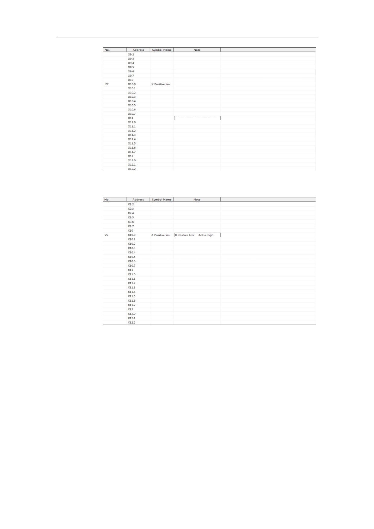
Here in X10.0 (the positive limt direction of X axis) as an example to introduce.
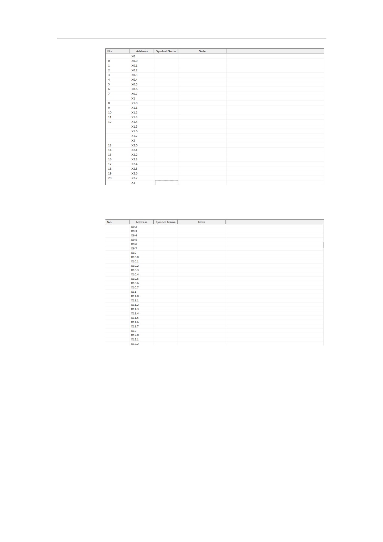
X10.0 is in X register. Select X register in the selection box of register. X10.0 is
in X000-X0049.
All the register bits and points from X0000 and X0049 may appear in the edit
box of register.
283
HNC-8-PLC Programming specification
8 . PLC Development environment description
Click “Symbol name” item at the X10.0 row three times, then the edit
box pops up.
Type “positive X limit”, and hit Enter button.
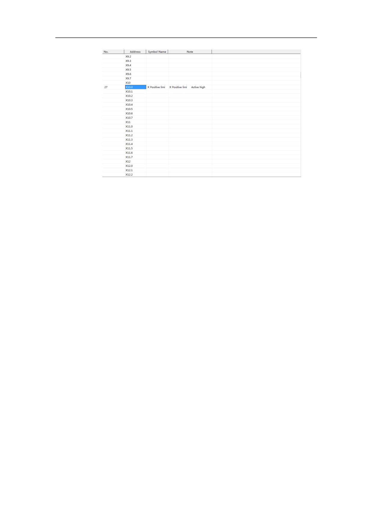
After typing the symbol name, annotate the address. The edit box will
pop up, with the three-click on the “comments” item at the X10.0
row.
284
HNC-8-PLC Programming specification
8 . PLC Development environment description
Type “positive X limit, active high” in the edit box, and hit Enter button.
Then defining the symbol name of X10, and annotating X10.0 are
complete.
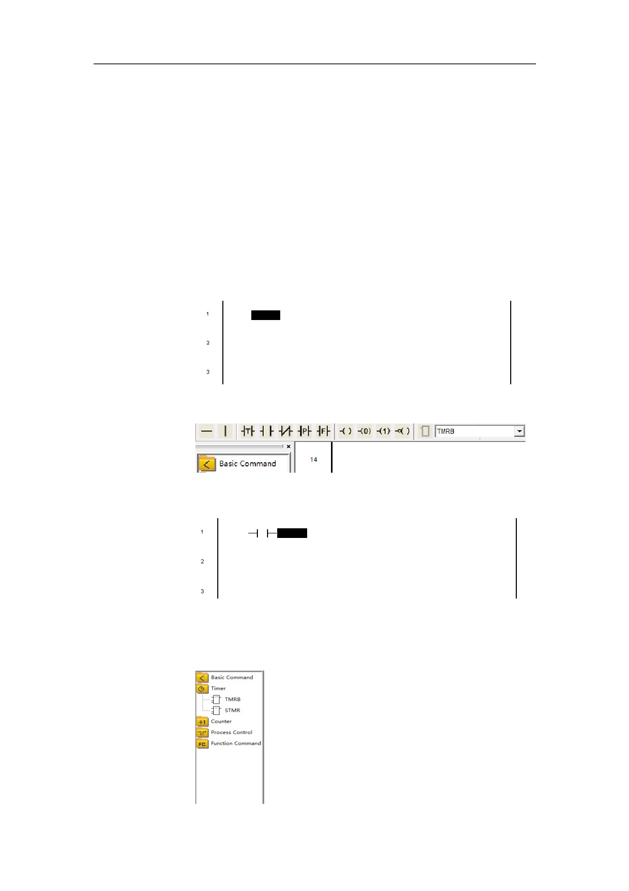
Delete Symbol List
When the symbol name and comments of X10.0 are not needed, delete them.
Select “X10.0” in the column of address, and hit Delete button, to delete X10.0
from the list.
285
HNC-8-PLC Programming specification
8 . PLC Development environment description
286
HNC-8-PLC Programming specification
8 . PLC Development environment description
Ladder Diagram Operation
The ladder diagram is composed of rows which themselves have up to 10 cells.
插入元件 Inserting Component
Inserting components can be separated into two types: inserting basic
components and inserting functional components.
¾ Inserting basic components
(1) When you want to insert basic component, first select a position on the
ladder diagram.
(2) Click the basic component to be inserted on the toolbar.
(3) Then the component is inserted in the ladder diagram.
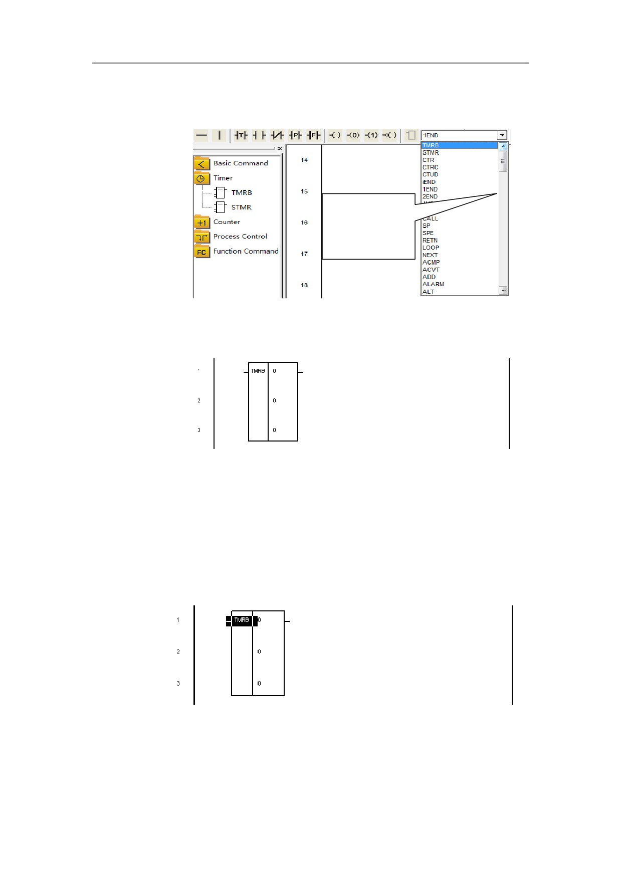
¾ Inserting functional components
(1) Select the functional components needed from the primitive tree.
287
HNC-8-PLC Programming specification
8 . PLC Development environment description
Or select it from the selection box of component on the toolbar.
Component
library
(2) Double-left click the ladder diagram, then the functional component is
inserted.
Deleting Component
Select the component to be deleted in the ladder diagram, and hit Delete button
to delete it.
288
HNC-8-PLC Programming specification
8 . PLC Development environment description
289
HNC-8-PLC Programming specification
8 . PLC Development environment description
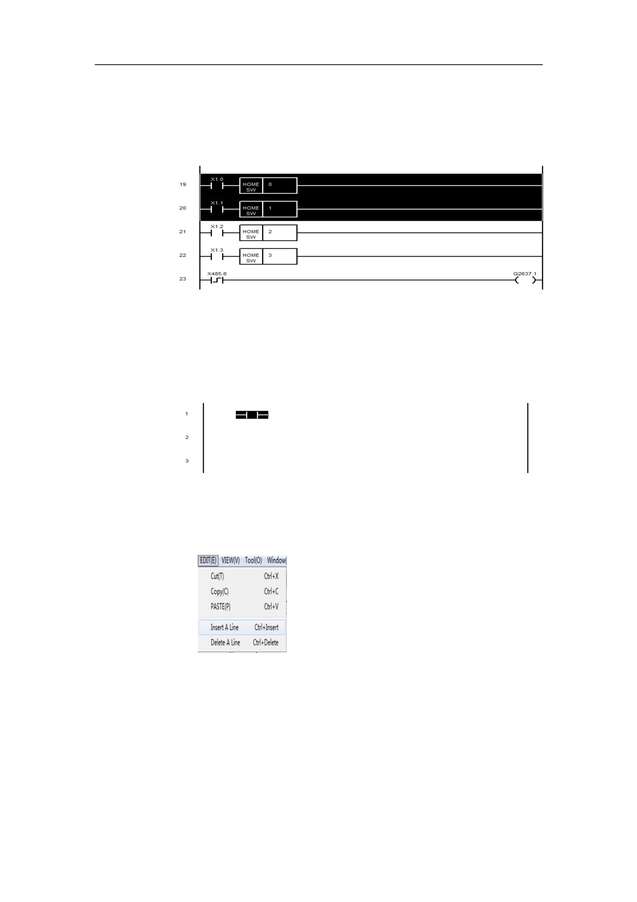
Deleting Multi-row
Select the rows needed to be deleted. (Drag the mouse to select the area to be
deleted)
Hit Delete button to delete the selected area.
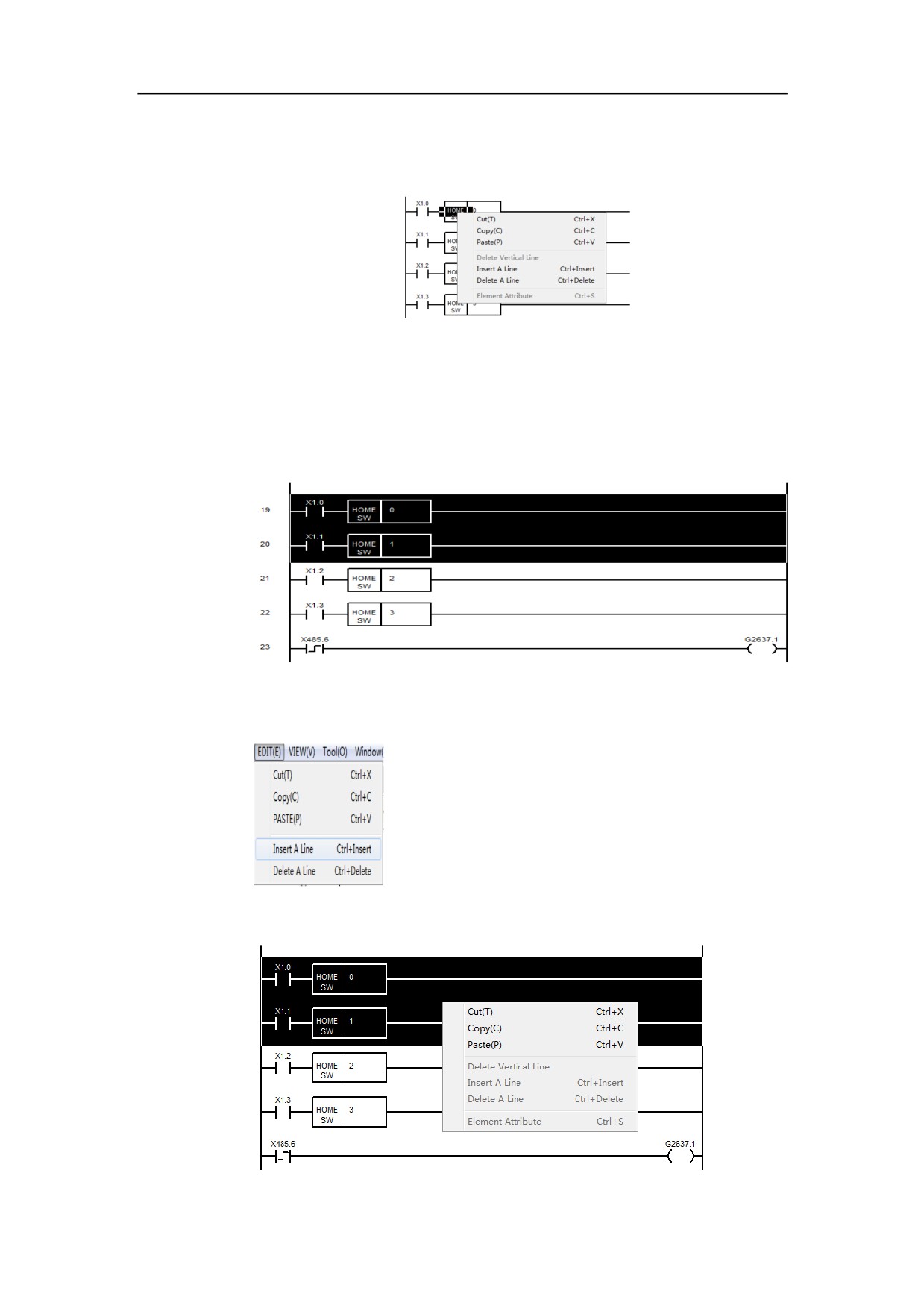
Cutting, Copying and Pasting Component
First select a component in the ladder diagram.
Then choose “Cut” or “Copy” in the “Edit” menu. Or right-click the component
to be cut or copied, and select “Cut” or “Copy”.
¾ The first way
¾ The second way
290
HNC-8-PLC Programming specification
8 . PLC Development environment description
At last, paste the component on other locations.
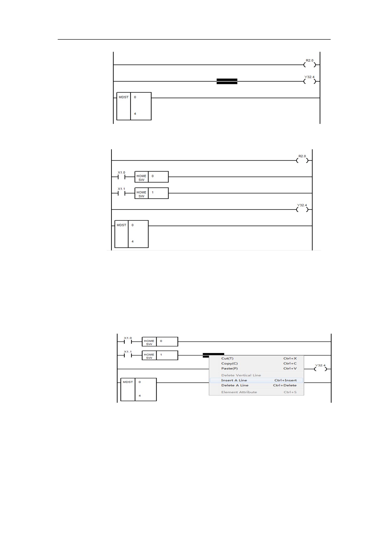
Cutting, Copying and Pasting Multi-row
The first step: drag the mouse to select the rows to be cutted or copied.
The second step: click
“Cut” or
“Paste” in the menu. Or right-click the
component to be cut or copied, and click “Cut” or “Paste”.
The third step: select somewhere on the ladder diagram.
291
HNC-8-PLC Programming specification
8 . PLC Development environment description
The forth step: Click “Paste”
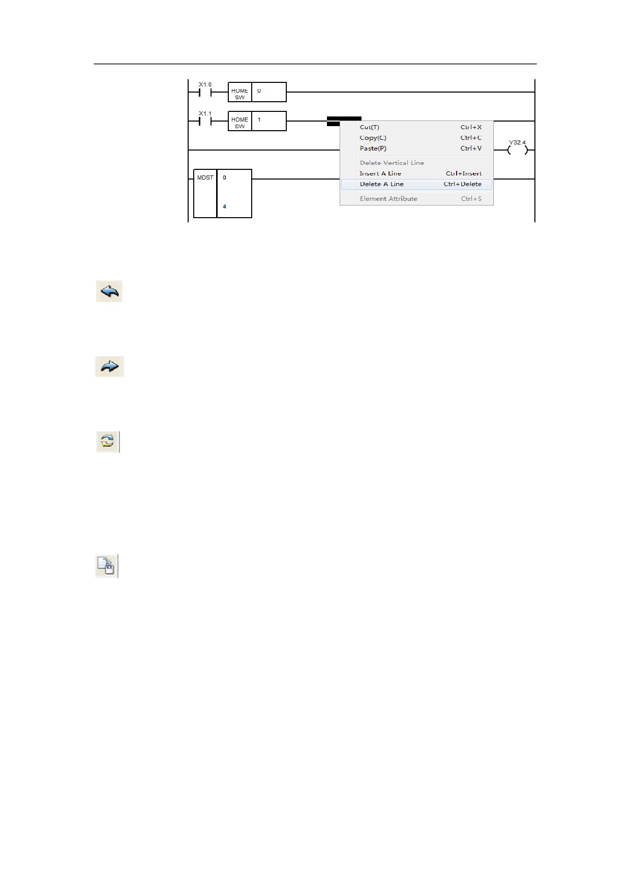
Insert Row
A row can be inserted before the position selected in the ladder diagram.
Delete Row
Can delete a row selected in the diagram.
292
HNC-8-PLC Programming specification
8 . PLC Development environment description
Undo
Using this button in the toolbar to undo the previous operations
Redo
Select this button on the toolbar to recover the undone operations.
Conversion
Using this button to convert the current ladder diagram to the corresponding
statement list. If there are errors in the ladder diagram, the message box
showing error information will pop up.
Output
Using this button to convert the current ladder diagram to the corresponding
statement list, and output the plc.dit file (execution file of ladder diagram). If
there are errors in the ladder diagram, the message box showing error
information will pop up.
Statement List Operation
Edit
293
HNC-8-PLC Programming specification
8 . PLC Development environment description
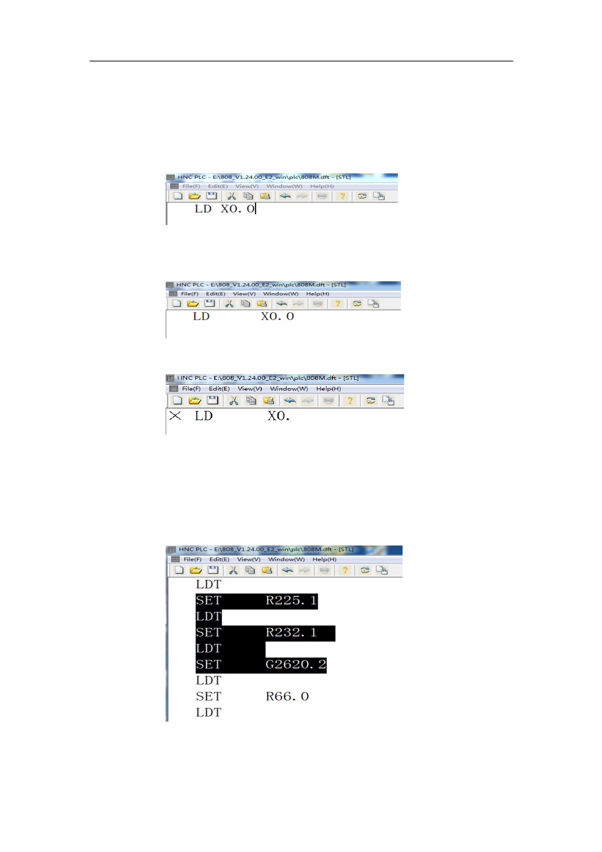
In the statement list, type characters directly to edit the statement list.
After a line of statement has been typed and the cursor is moved away, the
system will check and arrange the line.
If there are errors in this line, the statement list will annotate the errors.
Cut, Copy and Paste
Use the mouse to drag on the statement list, to select some statements.
Then use Cut, Copy and Paste in the menu, to work accordingly.
294

HNC-8-PLC Programming specification
8 . PLC Development environment description
Conversion
Select this button on the toolbar, to convert the current statement list to the
corresponding ladder diagram.
Output
Hit this button on the toolbar to convert the current ladder diagram to the
corresponding statement list, and output the plc.dit file (execution file of ladder
diagram).
295