HNC-8 Numerical Control System Software. Maual of PLC Programming (V1.24) - page 8
HNC-8-PLC Component specification
6. Extended function module
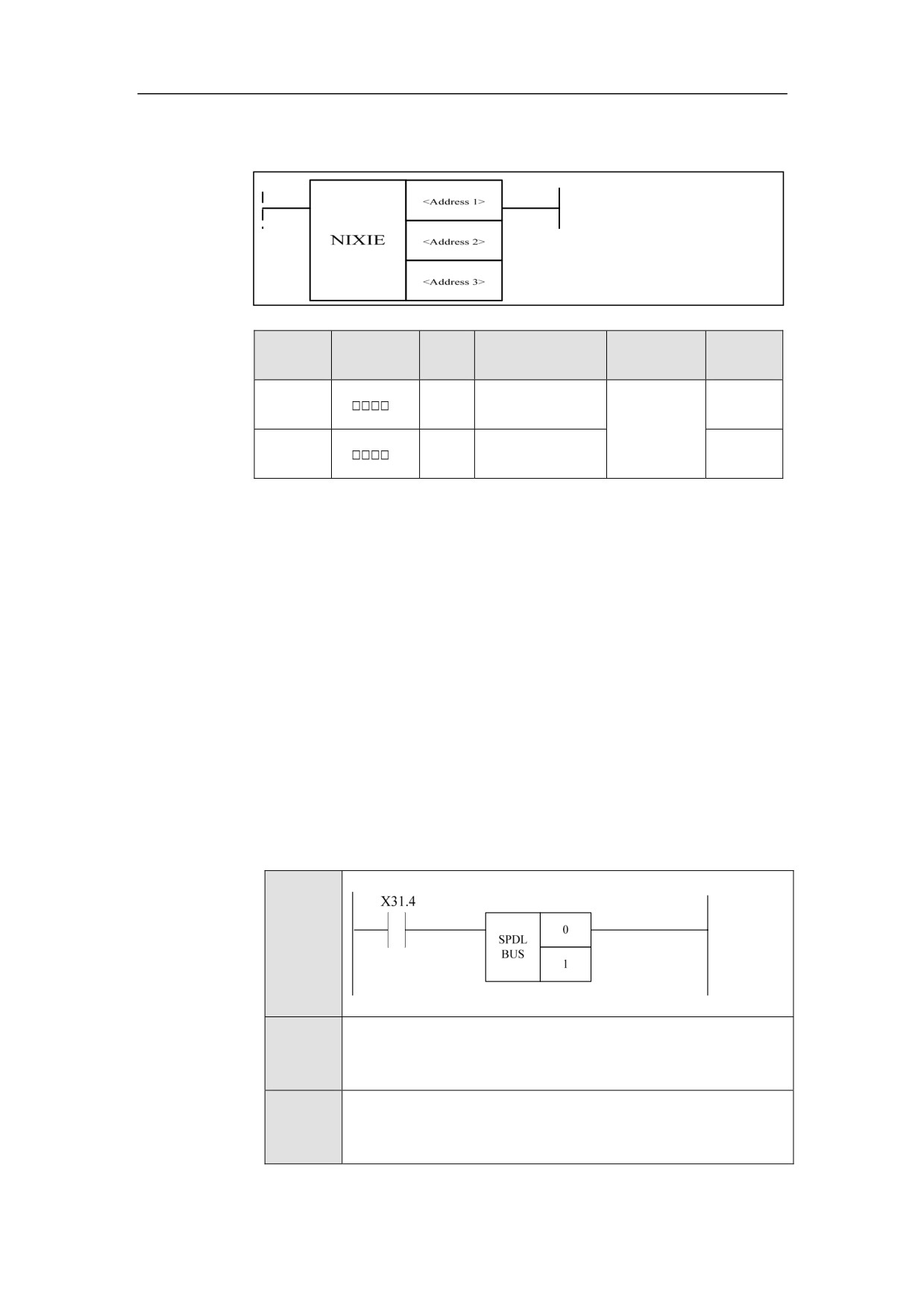
Spindle Control【Servo Spindle】SPDLBUS
Format
Paramet
Parameter
Data
Properti
Storage area
Explanation
er
form
type
es
<Addres
INT
Constant
Pre ○
s 1>
<Addres
INT
Constant
Post ×
s 2>
Function
A spindle in a channel is set to be valid. Set the device which is set to be
associated with the spindle number by the channel parameter, to the spindle. For
example, the logical axis number of the 0 axis for the current channel 0 is 5,
(suppose No.5 axis is enabled), then the logical axis 5 is regarded as the first
spindle of the current channel. The spindle is enabled to be effective by this
functional module.
Parameter
Parameter 1: channel number
Parameter 2: spindle number
Example
Ladder
Diagram
Stateme
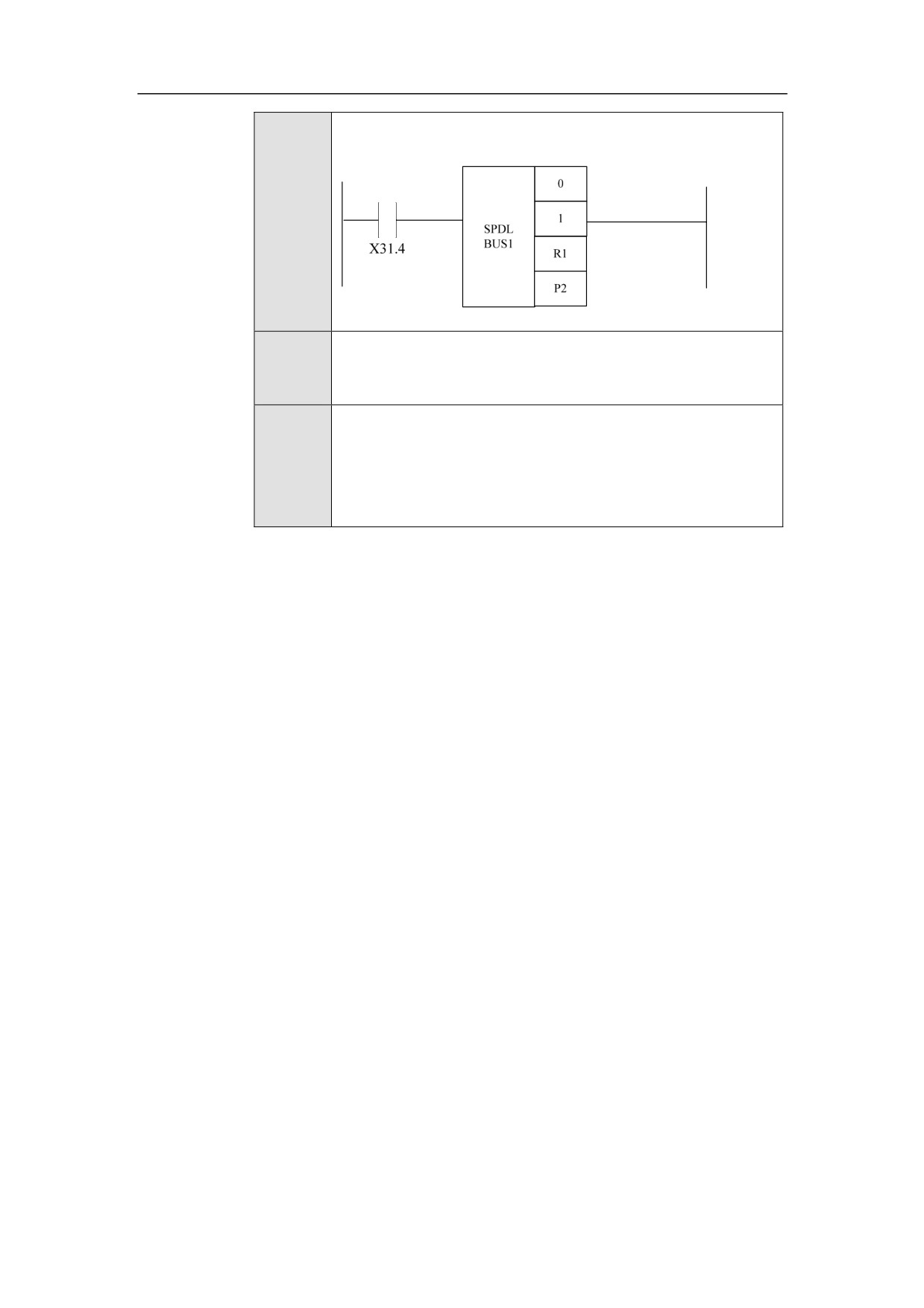
SPDLBUS 0 1
nt List
Descripti
When X31.4 is effective, the No.1 spindle of channel
0 is
on
controlled.
203
HNC-8-PLC Component specification
6. Extended function module
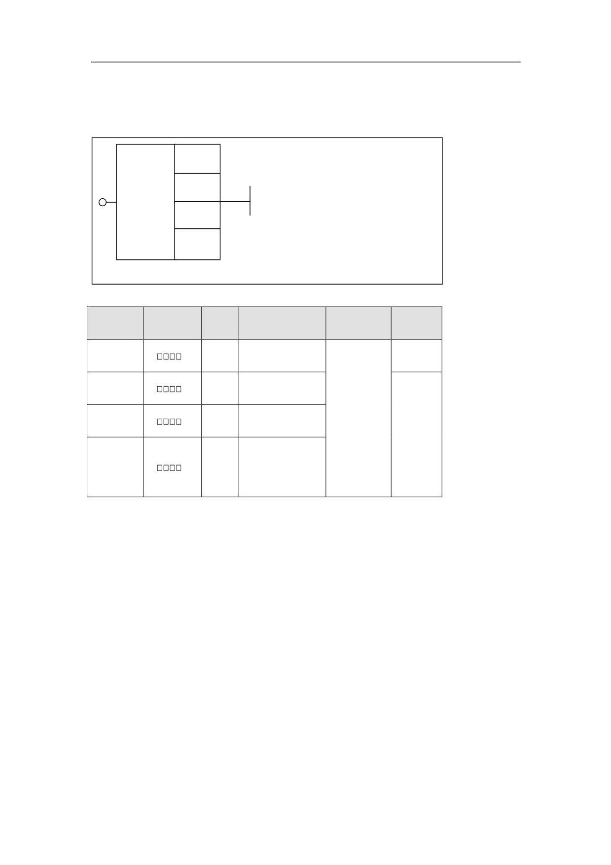
Spindle Control with Gear【Servo Spindle】SPDLBUS1
Format
<Address 1>
<Address 2>
SPDL
BUS1
<Address 3>
<Address 4>
Paramete
Parameter
Data
Properti
Storage area
Explanation
r
form
type
es
<Address
INT
Constant
Pre ○
1>
<Address
INT
Constant
2>
<Address
Constant, Y, G, R,
INT
3>
W, D, B
<Address
INT
P
4>
Function
Bus spindle control with gear.
Parameter
Parameter 1: channel number.
Parameter 2: spindle number.
Parameter 3: gear register, with gear starting with 1.
Parameter 4: control parameter. The specified parameter holds the data such as
maximum rotational speed of spindle motor, initial rotational speed and the like.
Reference value of spindle control value for parameter 4 includes:
204

HNC-8-PLC Component specification
6. Extended function module
0
Maximum rotational speed of motor
1
Minimum rotational speed of actual measurement
2
Maximum rotational speed of actual measurement
3
Numerator of current transmission ratio
4
Denominator of current transmission ratio
205
HNC-8-PLC Component specification
6. Extended function module
Example
Ladder
Diagram
Stateme
nt List
When X31.4 is effective, the current gear for No.
1 spindle
Descripti
override of channel 0 is in R1 register. Control parameter is in
on
user paramters from P2. Refer to the Parameter manual for filling
in parameters, according to the actual condition of machine.
206
HNC-8-PLC Component specification
6. Extended function module
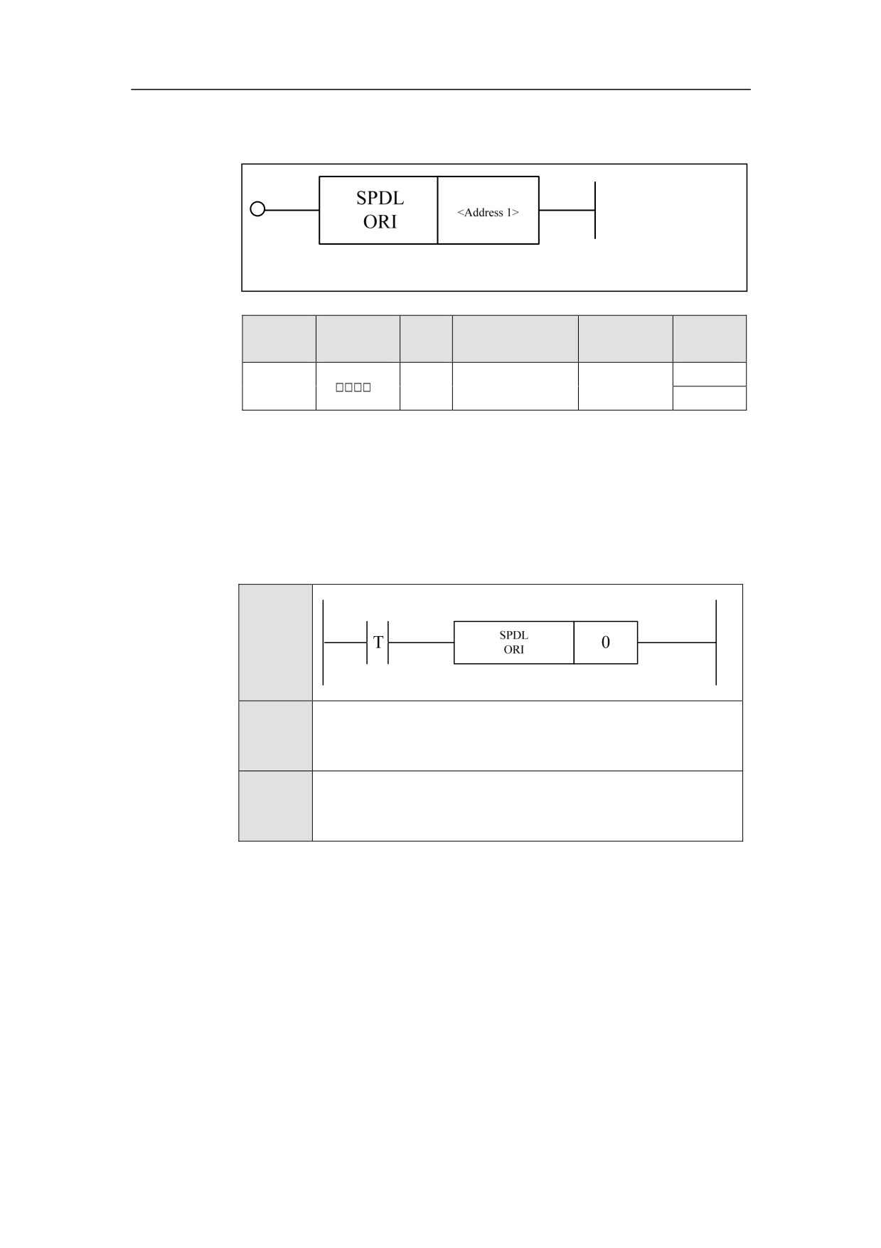
Spindle Orientation Enable SPDLORI
Format
Paramet
Parameter
Data
Properti
Storage area
Explanation
er
form
type
es
<Addres
Axis
Pre ○
INT
Constant
s 1>
number
Post ×
Function
Spindle orientation enable. The spindle needs to be directed to a specified angle
at the beginning of tool changing and rigid tapping. Perform spindle orientation
via this function. The orientation angle is set by the parameter in the servo
amplifier.
Example
Ladder
Diagram
Stateme
SPDLORI 0
nt List
Descripti
The spindle orientation for No.0 spindle.
on
207
HNC-8-PLC Component specification
6. Extended function module
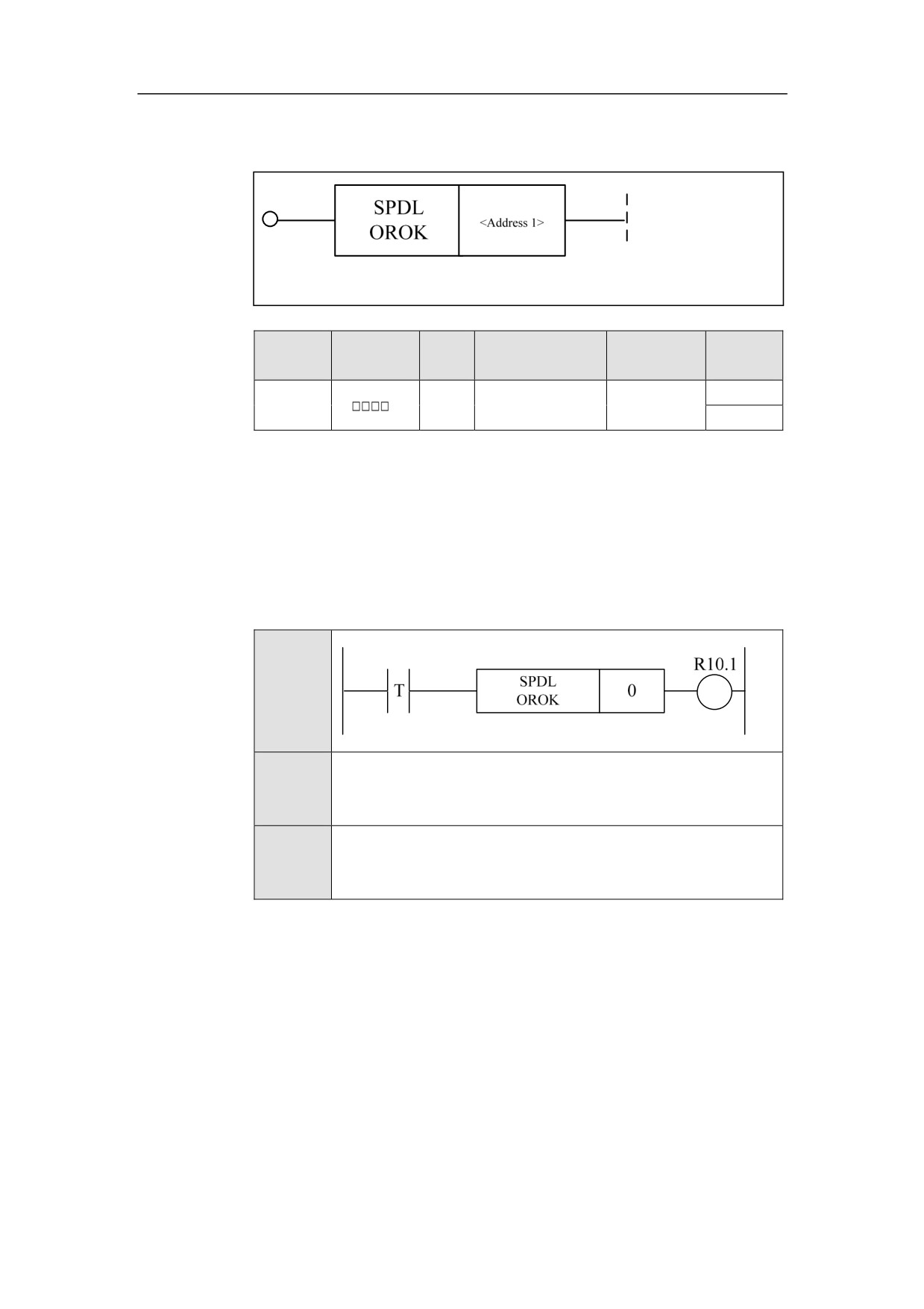
Completing Spindle Orientation SPDLOROK
Format
Paramet
Parameter
Data
Properti
Storage area
Explanation
er
form
type
es
<Addres
Pre ○
INT
Constant
s 1>
Post √
Function
orientation is complete, which indicates that the spindle has been at the specified
orientation angle.
The spindle
Parameter
Parameter 1:轴号。Parameter 1: axis number
Example
Ladder
Diagram
Stateme
SPDLOROK 0
nt List
Descripti
When No.0 spindle orientation has been enabled, set R10.1 to be
on
effective.
208
HNC-8-PLC Component specification
6. Extended function module
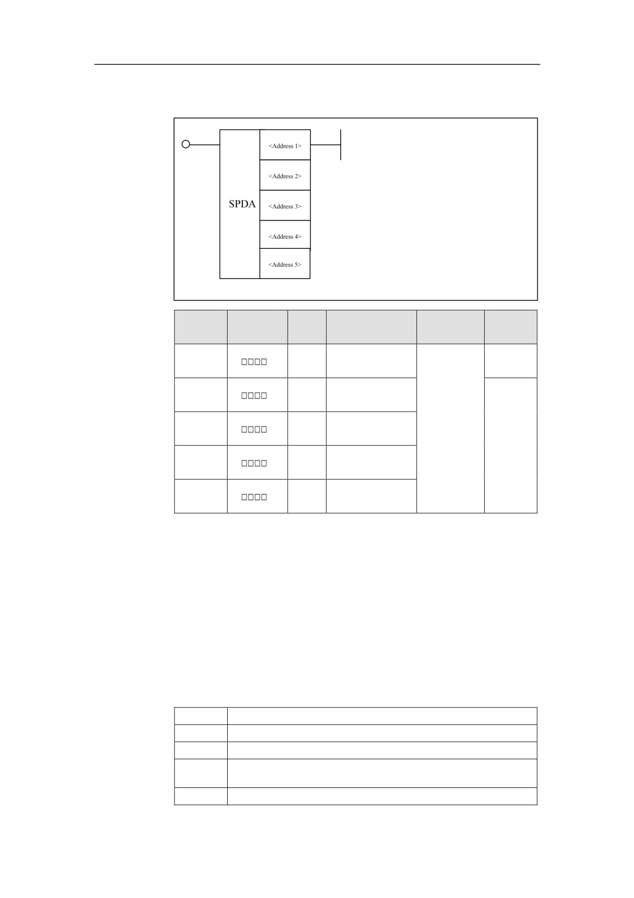
Spindle Control【DA】SPDA
Format
Paramet
Parameter
Data
Properti
Storage area
Explanation
er
form
type
es
<Addres
INT
Constant
Pre ○
s 1>
<Addres
INT
Constant
s 2>
<Addres
Constant, Y, G, R,
INT
s 3>
W, D, B
Post ×
<Addres
BOOL
Y, G, R, W, D, B
s 4>
<Addres
BOOL
P
s 5>
Function
DA control of spindle. It is used to control the analog spindle.
Parameter
Parameter 1: channel number
Parameter 2: spindle number
Parameter 3: gear register(gear starts from 1)
Parameter 4:invalid
Parameter 5:reference of spindle control value includes:
0
Maximum rotational speed of motor
1
Minimum rotational speed of actual measurement
2
Maximum rotational speed of actual measurement
3
Numerator of current transmission ratio
4
Denominator of current transmission ratio
209
HNC-8-PLC Component specification
6. Extended function module
Example
Ladder
Diagram
Stateme
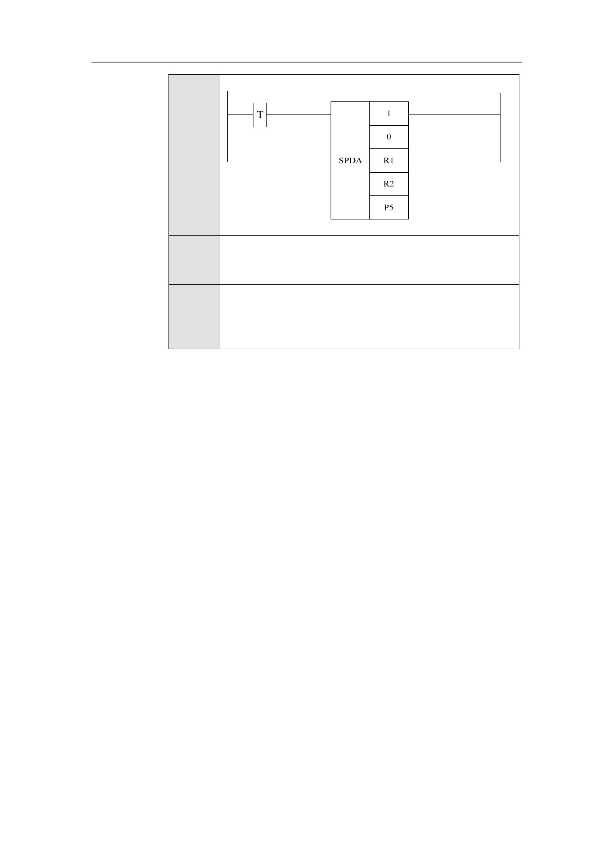
SPDA 1 0 R1 R2 P5
nt List
Channel 1. The current gear for spindle 0 of channel 1 is in R1
Descripti
register. The reference value of spindle control is in R2. Control
on
parameter is in P5.
210
HNC-8-PLC Component specification
6. Extended function module
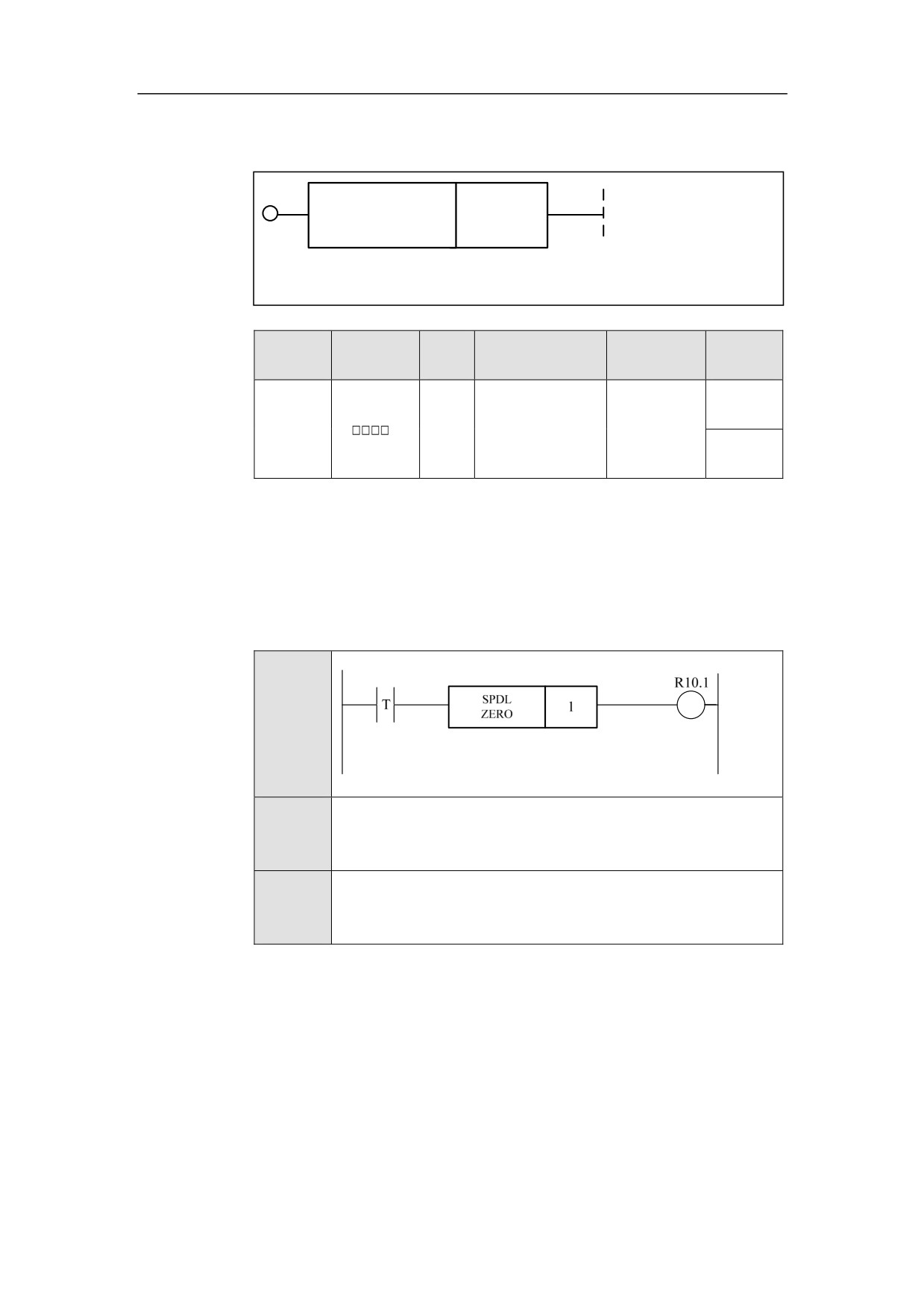
Zero Speed Detection for Spindle SPDLZERO
Format
SPDL
<Address 1>
ZERO
Paramet
Parameter
Data
Properti
Storage area
Explanation
er
form
type
es
Pre ○
<Addres
INT
Constant
s 1>
Post ×
Function
Zero speed detection for spindle.
Parameter
Parameter 1: axis number
Example
Ladder
Diagram
Stateme
SPDLZERO 1
nt List
Descripti
Zero speed detection for the No.1 spindle.
on
211
HNC-8-PLC Component specification
6. Extended function module
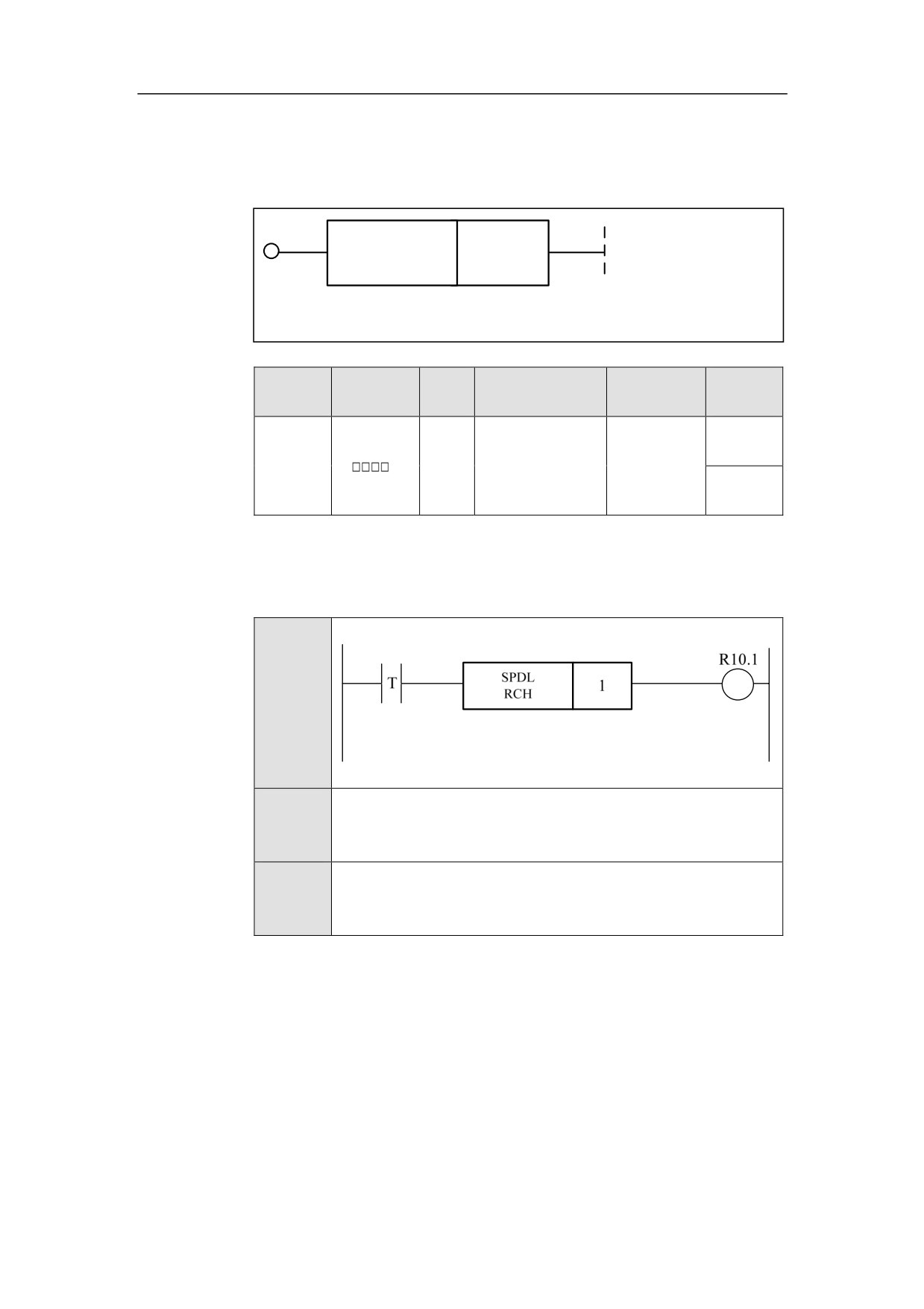
Spindle Speed Arrival SPDLRCH
Format
SPDL
<Address 1>
RCH
Paramet
Parameter
Data
Properti
Storage area
Explanation
er
form
type
es
Pre ○
<Addres
INT
Constant
Channel No.
s 1>
Post ×
Function
To detect whether the spindle speed reaches the instruction speed.
Example
Ladder
Diagram
Stateme
SPDLRCH 1
nt List
Descripti
Speed arrival for the No.1 spindle.
on
212
HNC-8-PLC Component specification
6. Extended function module
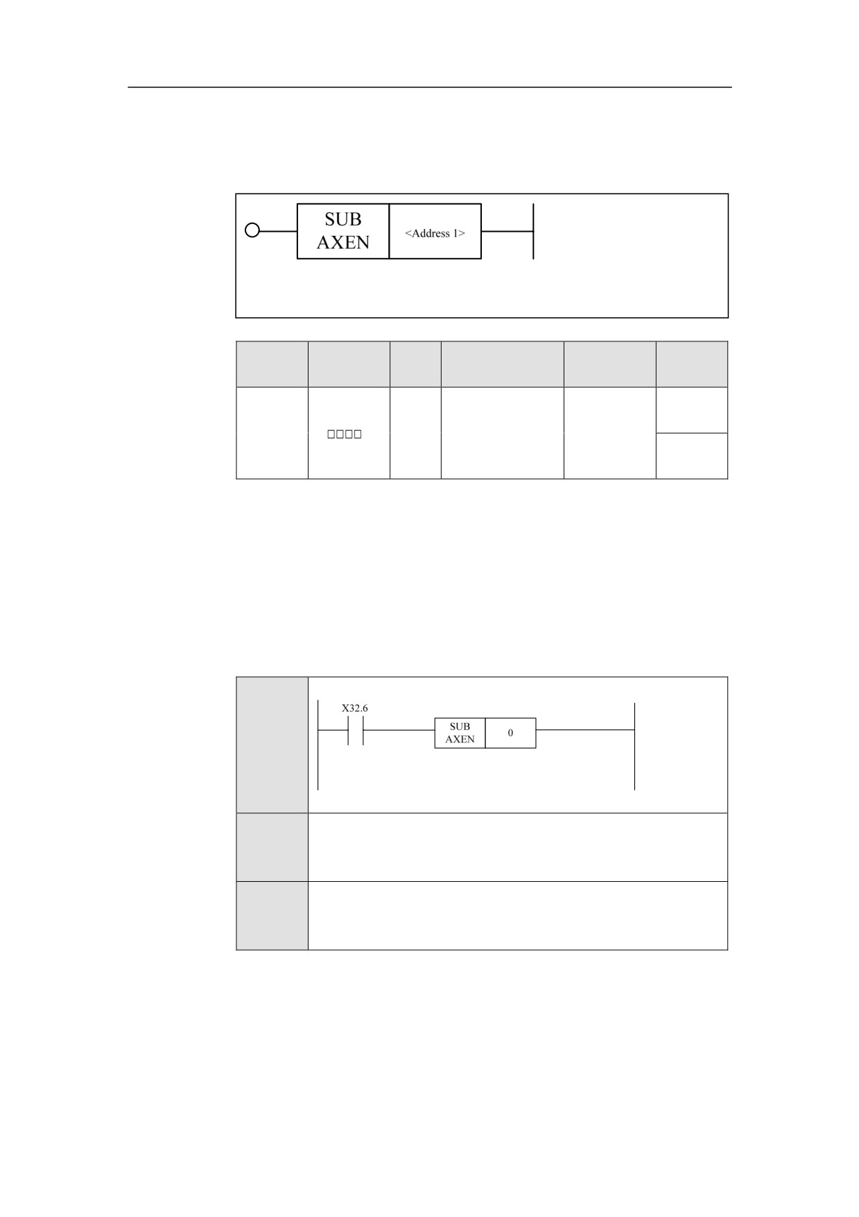
Driven Axis Home SUBAXEN
Format
Paramet
Parameter
Data
Properti
Storage area
Explanation
er
form
type
es
Pre √
<Addres
Channel
INT
Constant
s 1>
number
Post ×
Function
Enable the sub-axis to return to zero. When this function is turned on, the driven
axis returns home to search Z pulse. Z pulse has been found, which means
homing of driven axis is completed. Then the driving axis continues to return to
zero.
Parameter
Parameter 1: Driven-axis number
Example
Ladder
Diagram
Stateme
SUBAXEN 0
nt List
Descripti
When X32.6 is valid, the driven axis is enabled to return to zero.
on
213
HNC-8-PLC Component specification
6. Extended function module
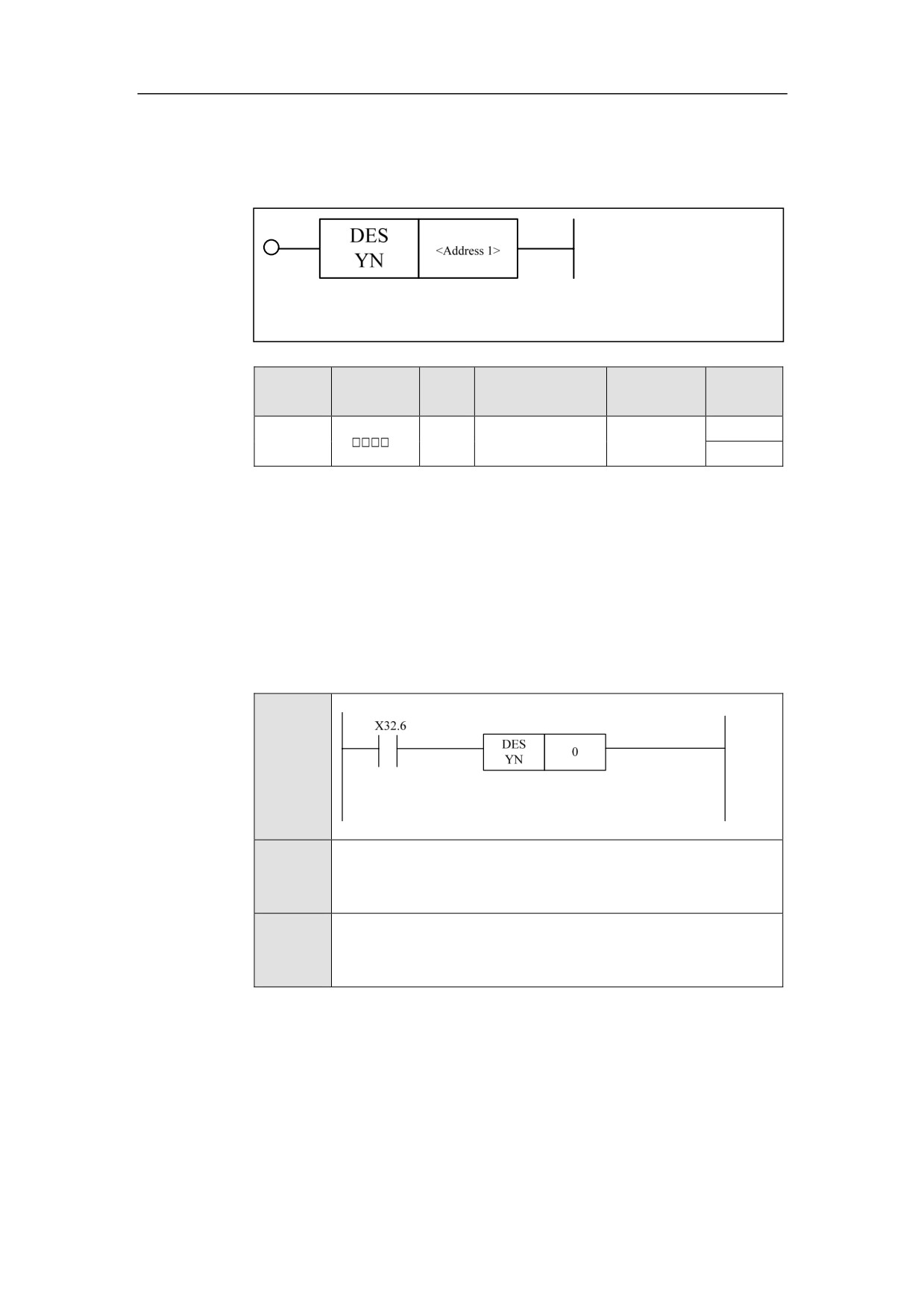
Release Driven Axis DESYN
Format
Paramet
Parameter
Data
Properti
Storage area
Explanation
er
form
type
es
<Addres
Pre √
INT
Constant
s 1>
Post ×
Function
Release driven axis. An axis is set to the driven axis of another one by parameter.
If some instructions are sent to driving axis, driven axis will also get those.
When the function of driven axis release is turned on, the driven axis is
disassociated with the driving axis, without receiving instruction pulse of the
driving axis.
Parameter
Parameter 1: Driven axis number
Example
Ladder
Diagram
Stateme
DESYN 0
nt List
Descripti
When X32.6 is valid, the No.0 driven axis is released.
on
214
HNC-8-PLC Component specification
6. Extended function module
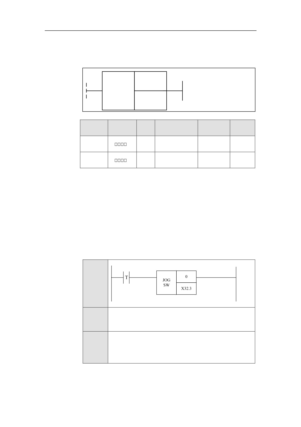
Axis Jog JOGSW
Format
<Address 1>
JOG
SW
<Address 2>
Paramete
Parameter
Data
Properti
Storage area
Explanation
r
form
type
es
<Address
Constant, X, Y, F,
INT
Pre ○
1>
G, R, W, D, P, B
<Address
X, Y, F, G, R, W,
BOOL
Post ×
2>
D, P, B
Function
Enable axis jog by manual.
Parameter
Parameter 1: axis number
Parameter 2: the positive direction of aix jog. The value of 1 indicates the
positive direction, and the value of 0 indicates the negative direction.
Example
Ladder
Diagram
Stateme
JOGSW 0 X32.3
nt List
When X32.3 is turned on, axis 0 is enabled to move manually in
Descripti
positive direction; when X32.3 is not turned on, axis 0 is enabled
on
to move manually in negative direction.
215
HNC-8-PLC Component specification
6. Extended function module
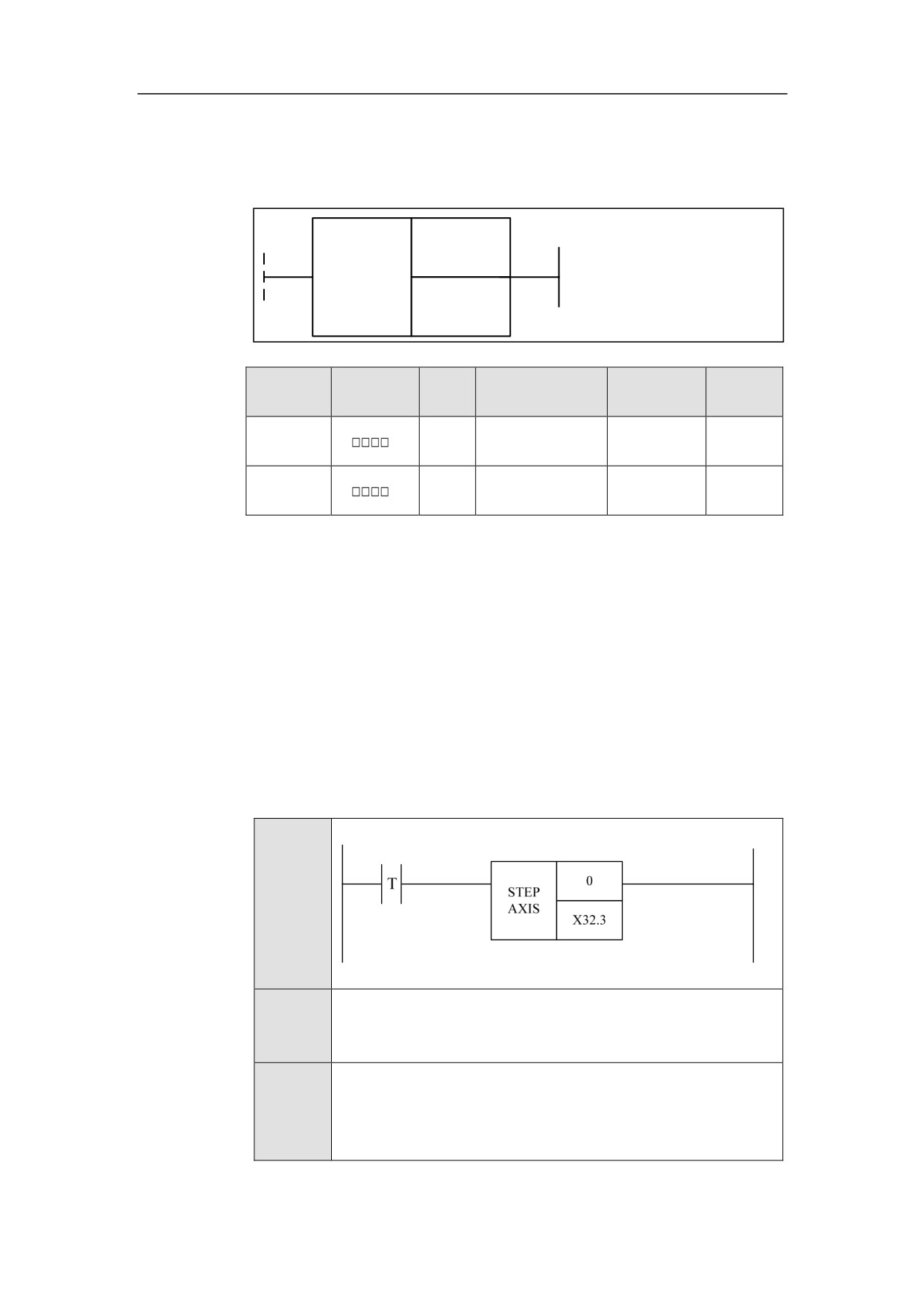
Axis Stepping STEPAXIS
Format
<Address 1>
STEP
AXIS
<Address 2>
Paramete
Parameter
Data
Properti
Storage area
Explanation
r
form
type
es
<Address
Constant, X, Y, F,
INT
Pre ○
1>
G, R, W, D, P, B
<Address
X, Y, F, G, R, W,
BOOL
Post ×
2>
D, P, B
Function
Enable axis by stepping.
Parameter
Parameter 1: axis number.
Parameter 2: the direction of axis stepping. “0” represents jog in the positive
direction, and “1” represents jog in the negative direction.
Example
Ladder
Diagram
Stateme
STEPAXIS 0 X32.3
nt List
When X32.3 is turned on, axis 0 is enabled to jog in negative
Descripti
direction; when X32.3 is not turned on, axis 0 is enabled to jog in
on
positive direction.
216
HNC-8-PLC Component specification
6. Extended function module
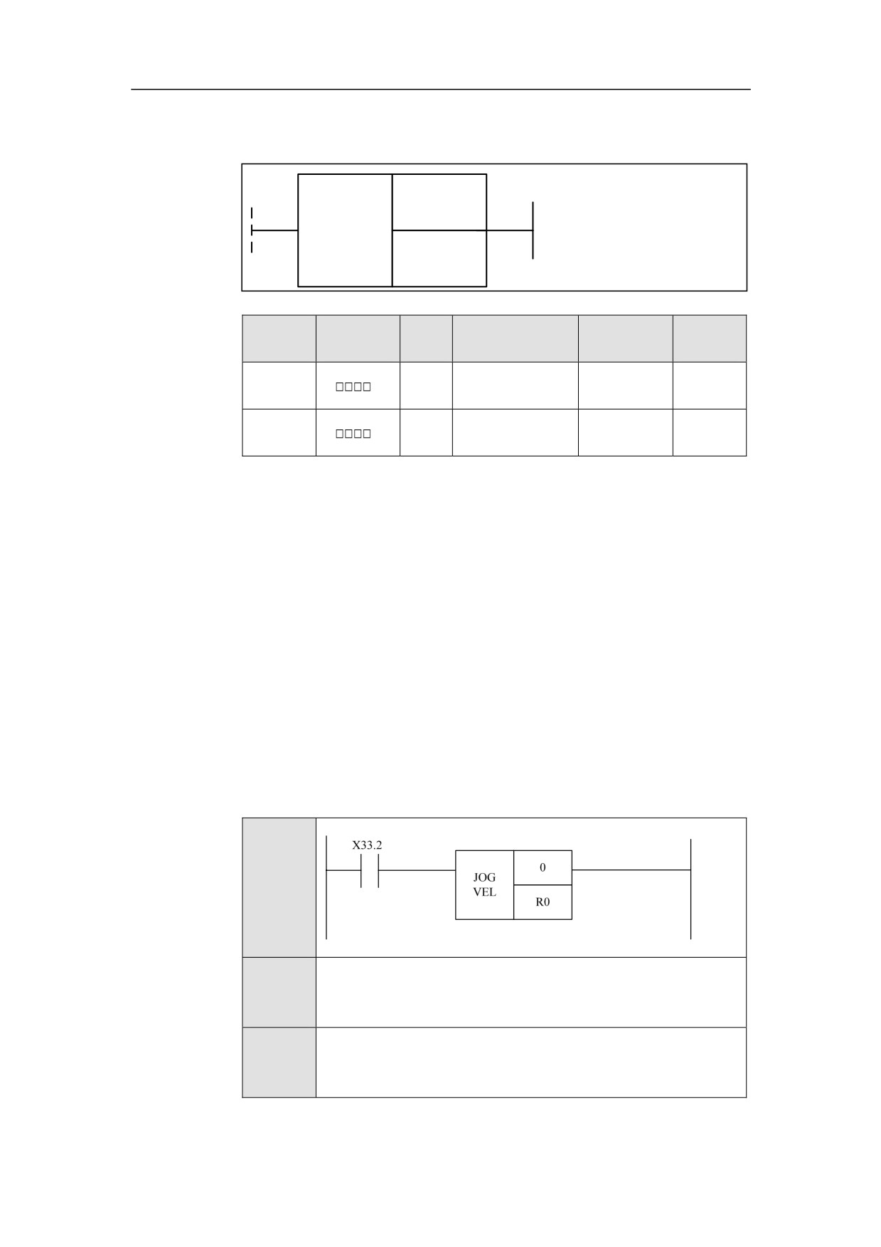
Jog Velocity JOGVEL
Format
<Address 1>
JOG
VEL
<Address 2>
Paramet
Parameter
Data
Properti
Storage area
Explanation
er
form
type
es
<Addres
Constant, X, Y, F,
INT
Pre √
s 1>
G, R, W, D, P, B
<Addres
Constant, X, Y, F,
INT
Post ×
s 2>
G, R, W, D, P, B
Function
Manually control the jog speed.
Parameter
Parameter 1: axis number
Parameter 2: axis speed, and its value can be as below:
1: og speed of parameter
2: apid traverse speed of parameter
>2: speed (pulse/circle)
Example
Ladder
Diagram
Stateme
JOGVEL 0 R0
nt List
Descripti
When X33.2 is turned on, the 0 axis runs at the speed specified in
on
R0.
217
HNC-8-PLC Component specification
6. Extended function module
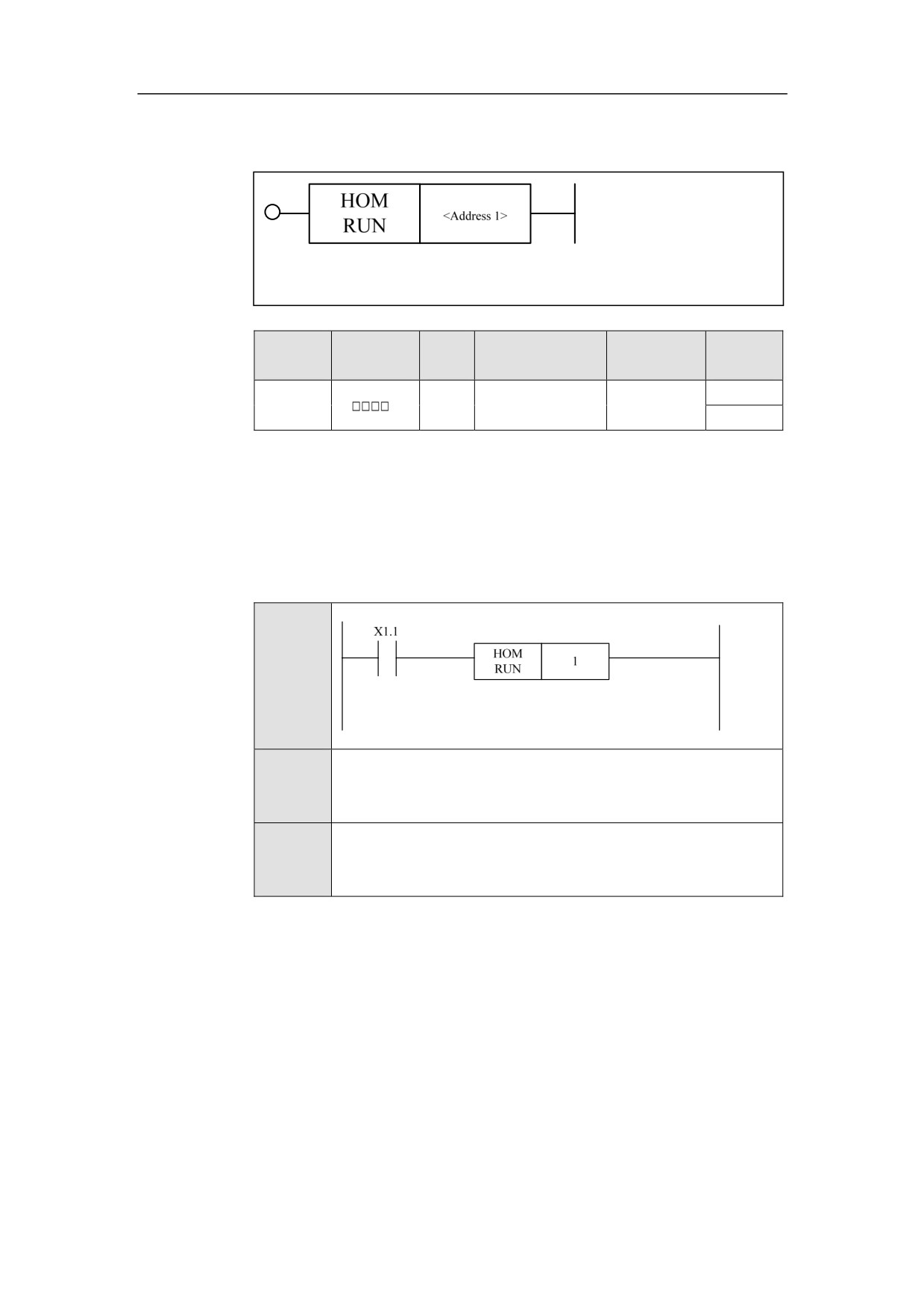
Home Run HOMRUN
Format
Paramet
Parameter
Data
Properti
Storage area
Explanation
er
form
type
es
<Addres
Pre √
INT
Constant
s 1>
Post ×
Function
To start to return home.
Parameter
Parameter 1: axis number
Example
Ladder
Diagram
Stateme
HOMRUN 1
nt List
Descripti
When X1.1 is turned on, the axis 1 starts to return home.
on
218
HNC-8-PLC Component specification
6. Extended function module
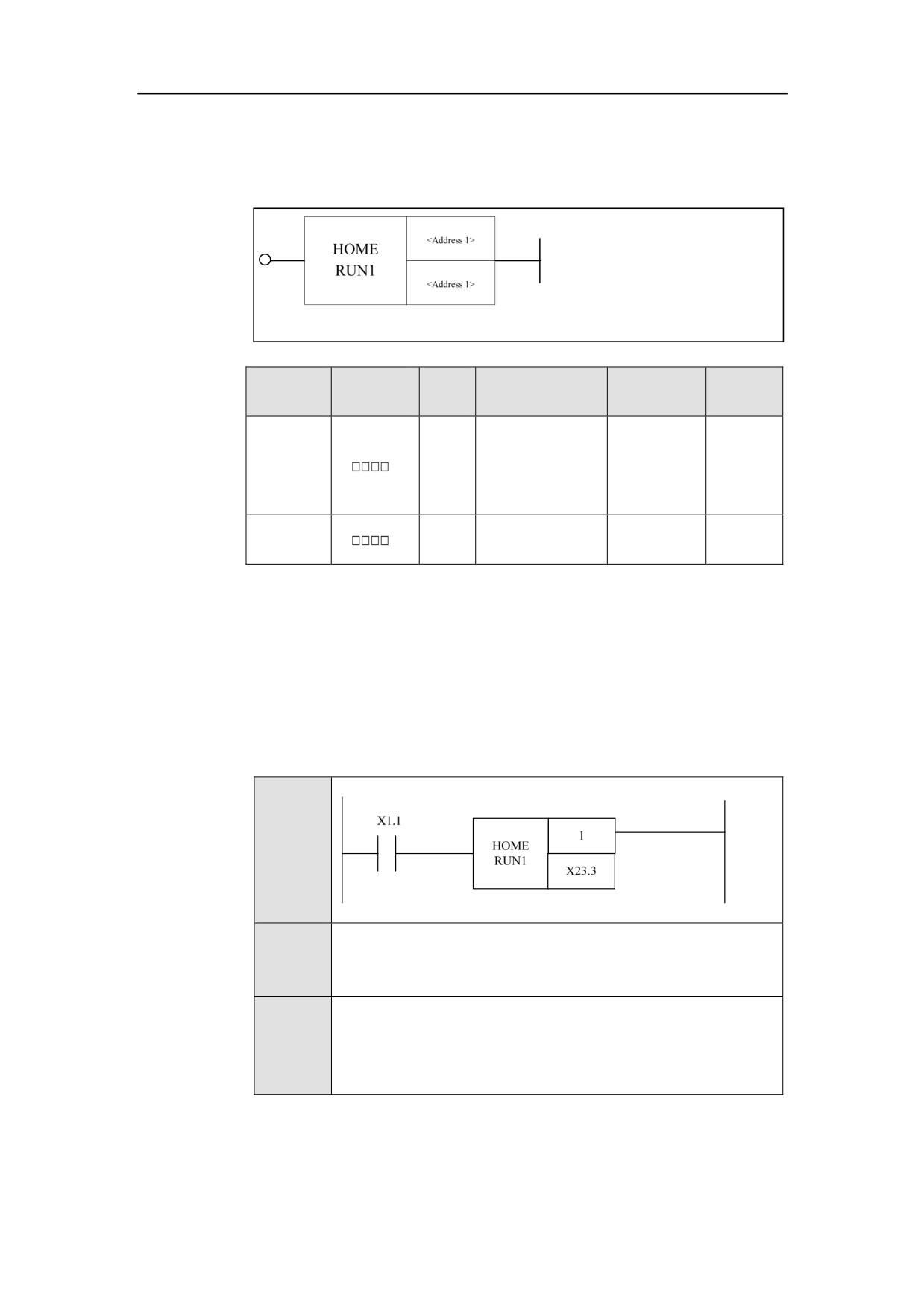
Home Run 1 HOMERUN1
Format
Paramete
Parameter
Data
Properti
Storage area
Explanation
r
form
type
es
<Address
INT
Constant
Pre √
1>
<Address
X, Y, F, G, R, W,
BOOL
Post ×
2>
D, P, B
Function
To start to return home.
Parameter
Parameter 1: axis number
Parameter 2: the direction where the axis returns home.
Example
Ladder
Diagram
Stateme
HOMERUN1
nt List
When X1.1 is turned on, the axis 1 starts to return home; when
Descripti
X23.3 is turned on, the Jog of axis 0 in positive direction is
on
enabled.
219
HNC-8-PLC Component specification
6. Extended function module
Home Approaching Switch HOMESW
Format
Paramet
Parameter
Data
Properti
Storage area
Explanation
er
form
type
es
<Addres
Pre √
INT
Constant
s 1>
Post ×
Function
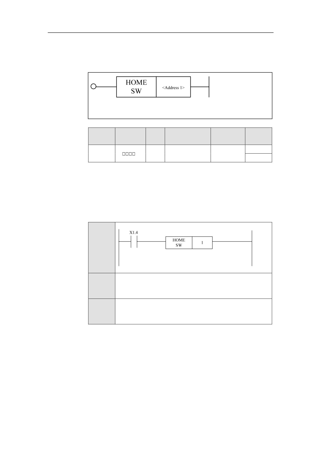
The axis meets the home block.
Parameter
Parameter 1: axis number
Example
Ladder
Diagram
Stateme
HOMESW 1
nt List
Descripti
X1.4 is turned on, which means the axis 1 meets the home block.
on
220
HNC-8-PLC Component specification
6. Extended function module
Home Completing HOMLED
Format
Paramet
Parameter
Data
Properti
Storage area
Explanation
er
form
type
es
<Addres
Pre √
INT
Constant
s 1>
Post √
Function
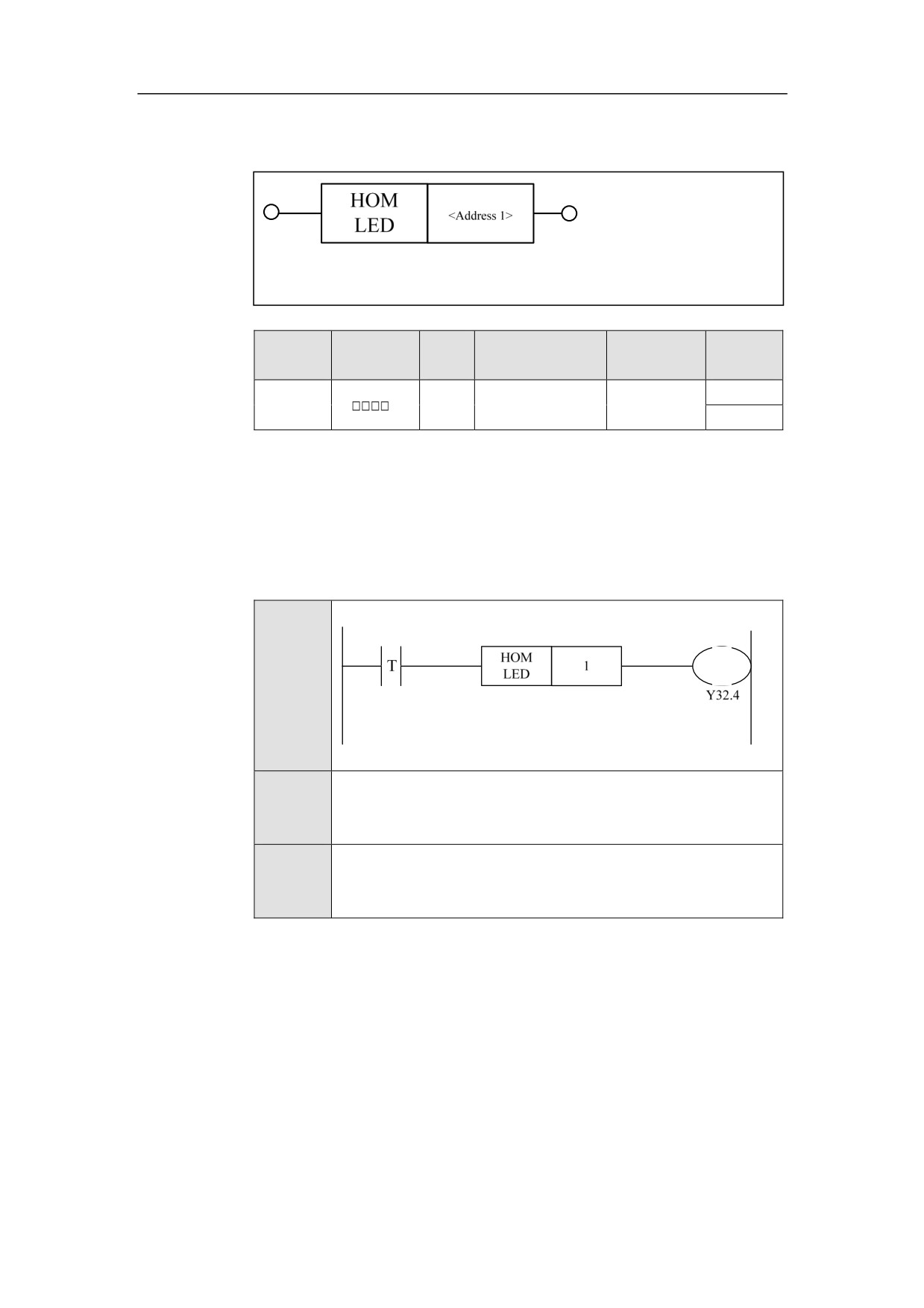
Returning home is complete.
Parameter
Parameter 1: axis number.
Example
Ladder
Diagram
Stateme
HOMLED 1
nt List
Descripti
Axis 1 has completed homing, and the lamp of axis 1 is lit.
on
221
HNC-8-PLC Component specification
6. Extended function module
Axis Enable AXEN
Format
AX
<Address 1>
EN
Paramet
Parameter
Data
Properti
Storage area
Explanation
er
form
type
es
<Addres
Pre √
INT
Constant
s 1>
Post ×
Function
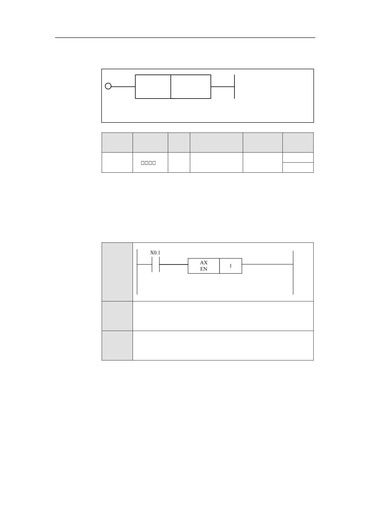
Axis enable.
Parameter
Parameter 1: axis number, can be constant and register.
Example
Ladder
Diagram
Stateme
AXEN 1
nt List
Descripti
When X0.1 is turned on, axis 1 is enabled.
on
222
HNC-8-PLC Component specification
6. Extended function module
Axis Ready (Bust) AXRDY
Format
Paramet
Parameter
Data
Properti
Storage area
Explanation
er
form
type
es
<Addres
Pre ×
INT
Constant
s 1>
Post √
Function
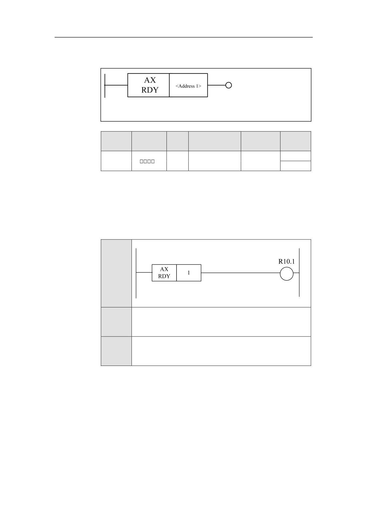
The axis is ready.
Parameter
Parameter 1: axis number.
Example
Ladder
Diagram
Stateme
AXRDY 1
nt List
Descripti
When the axis 1 has been ready, R10.1 is set to 1.
on
223
HNC-8-PLC Component specification
6. Extended function module
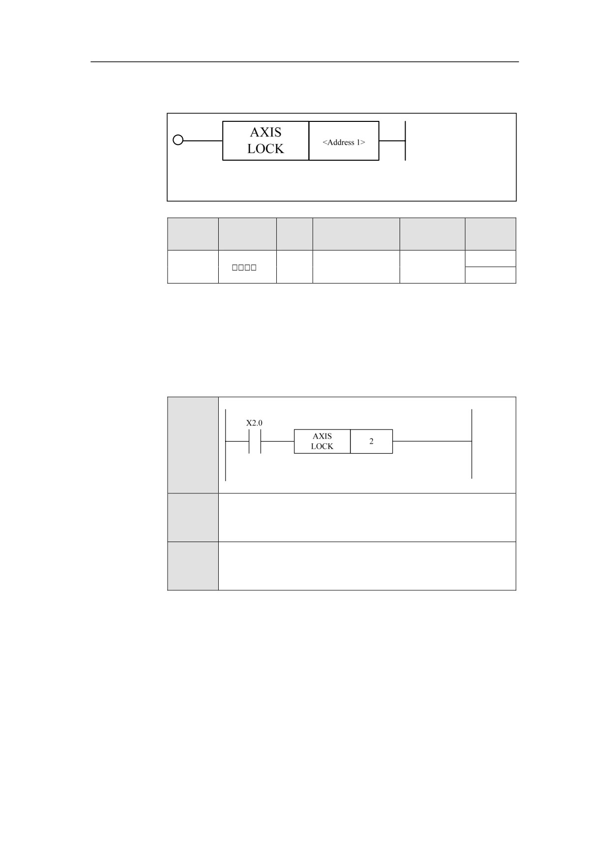
Axis Lock AXISLOCK
Format
Paramet
Parameter
Data
Properti
Storage area
Explanation
er
form
type
es
<Addres
Pre √
INT
Constant
s 1>
Post ×
Function
The axis is locked.
Parameter
Parameter 1: axis number.
Example
Ladder
Diagram
Stateme
AXISLOCK 2
nt List
Descripti
When X2.0 is turned on, the axis 2 is locked.
on
224
HNC-8-PLC Component specification
6. Extended function module
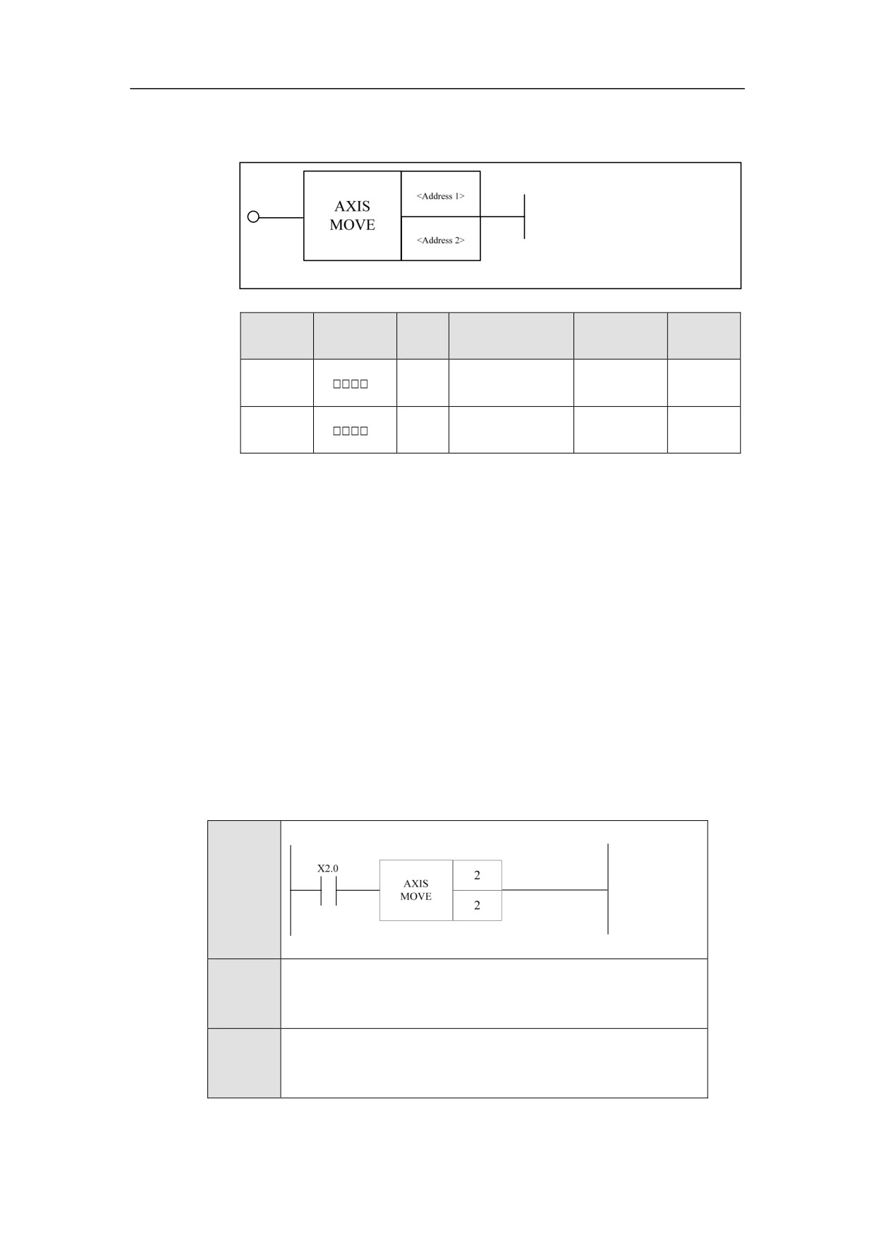
Relative PMC Axis Movement AXISMOVE
Format
Paramet
Parameter
Data
Properti
Storage area
Explanation
er
form
type
es
<Addres
Constant, X, Y, F,
INT
Pre √
s 1>
G, R, W, D, P, B
<Addres
Constant, X, Y, F,
INT
Post ×
s 2>
G, R, W, D, P, B
Function
PMC axis is a special motion axis, which cannot be moved by the instruction,
and cannot be used for the interpolation. The PMC axis can only be moved by
the PLC program. This instruction is used to move the PMC axis, and specify the
relative moving distance.
Parameter
Parameter 1: axis number
Parameter 2: axis movement (unit: 1/1000mm, or 1/1000 degree).
Example
Ladder
Diagram
Stateme
AXISMOVE 2 2
nt List
Descripti
When X2.0 is turned on, axis 2 relatively moves the distance of 2
on
units.
225
HNC-8-PLC Component specification
6. Extended function module
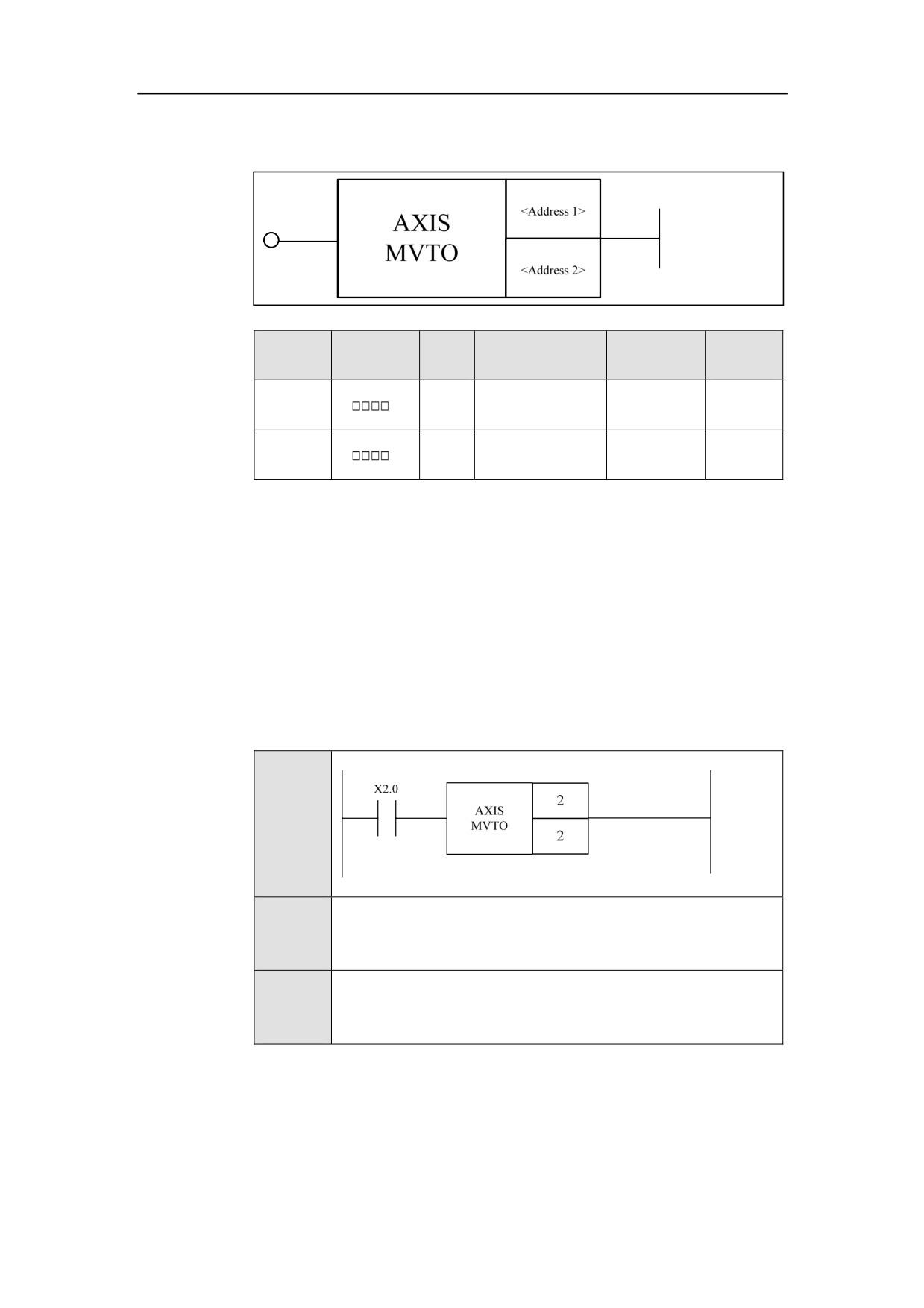
Absolute PMC Axis Movement AXISMVTO
Format
Paramet
Parameter
Data
Properti
Storage area
Explanation
er
form
type
es
<Addres
Constant, X, Y, F,
INT
Pre √
s 1>
G, R, W, D, P, B
<Addres
Constant, X, Y, F,
INT
Post ×
s 2>
G, R, W, D, P, B
Function
This instruction is used to move the PMC axis to an absolute position.
Parameter
Parameter 1: axis number
Parameter 2: the position that the axis moves
(unit:
1/1000mm, or 1/1000
degree).
Example
Ladder
Diagram
Stateme
AXISMVTO 2 2
nt List
Descripti
When X2.0 is turned on, the axis 2 moves to the position 2.
on
226
HNC-8-PLC Component specification
6. Extended function module
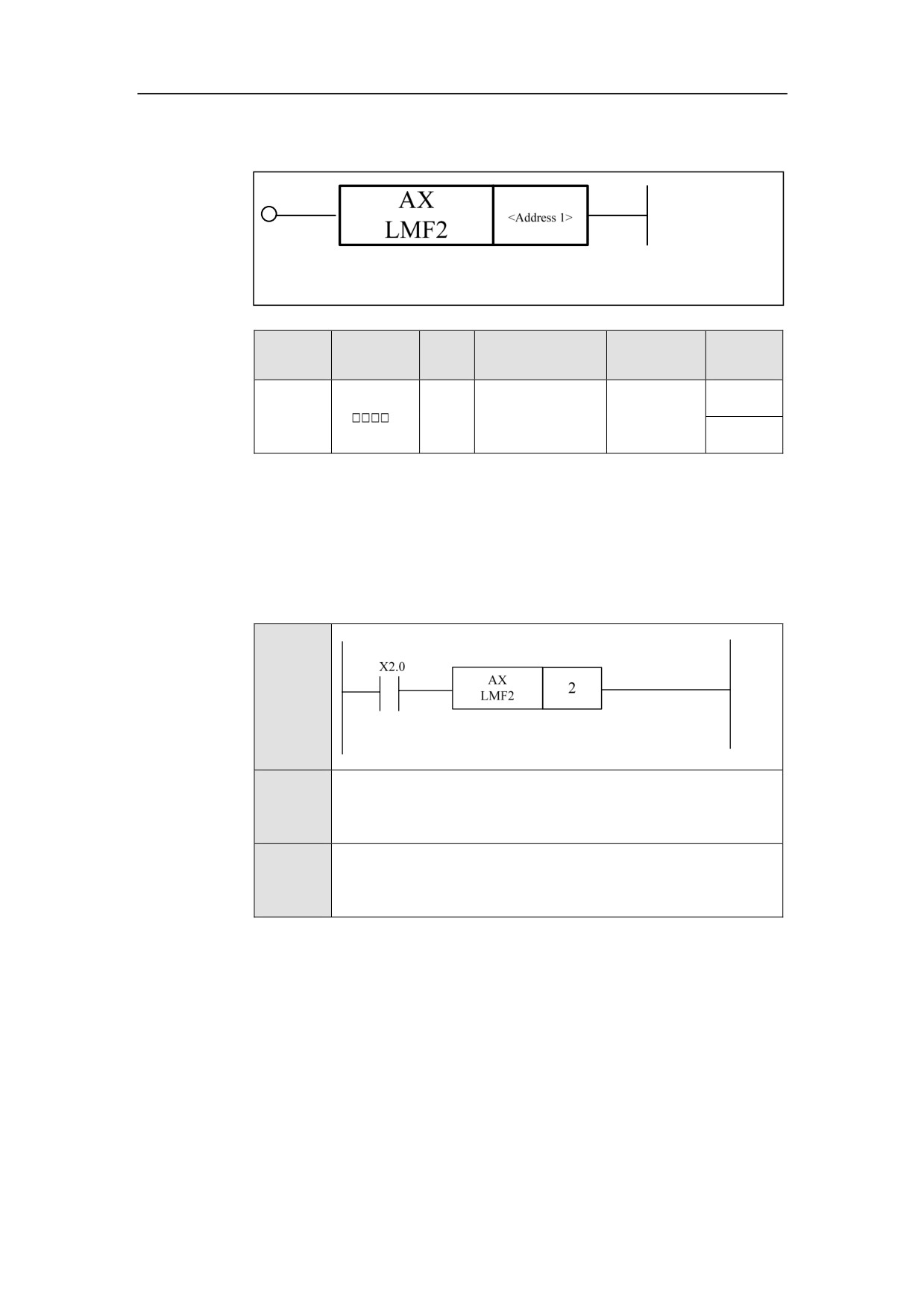
The Second Soft Limit of Axis AXLMF2
Format
Paramet
Parameter
Data
Properti
Storage area
Explanation
er
form
type
es
Pre √
<Addres
Constant, X, Y, F,
INT
s 1>
G, R, W, D, P, B
Post ×
Function
The second soft limit of the axis.
Parameter
Parameter 1: axis number.
Example
Ladder
Diagram
Stateme
AXLMF2 2
nt List
Descripti
When X2.0 is turned on, the second soft limit of the axis 2 is
on
effective.
227
HNC-8-PLC Component specification
6. Extended function module
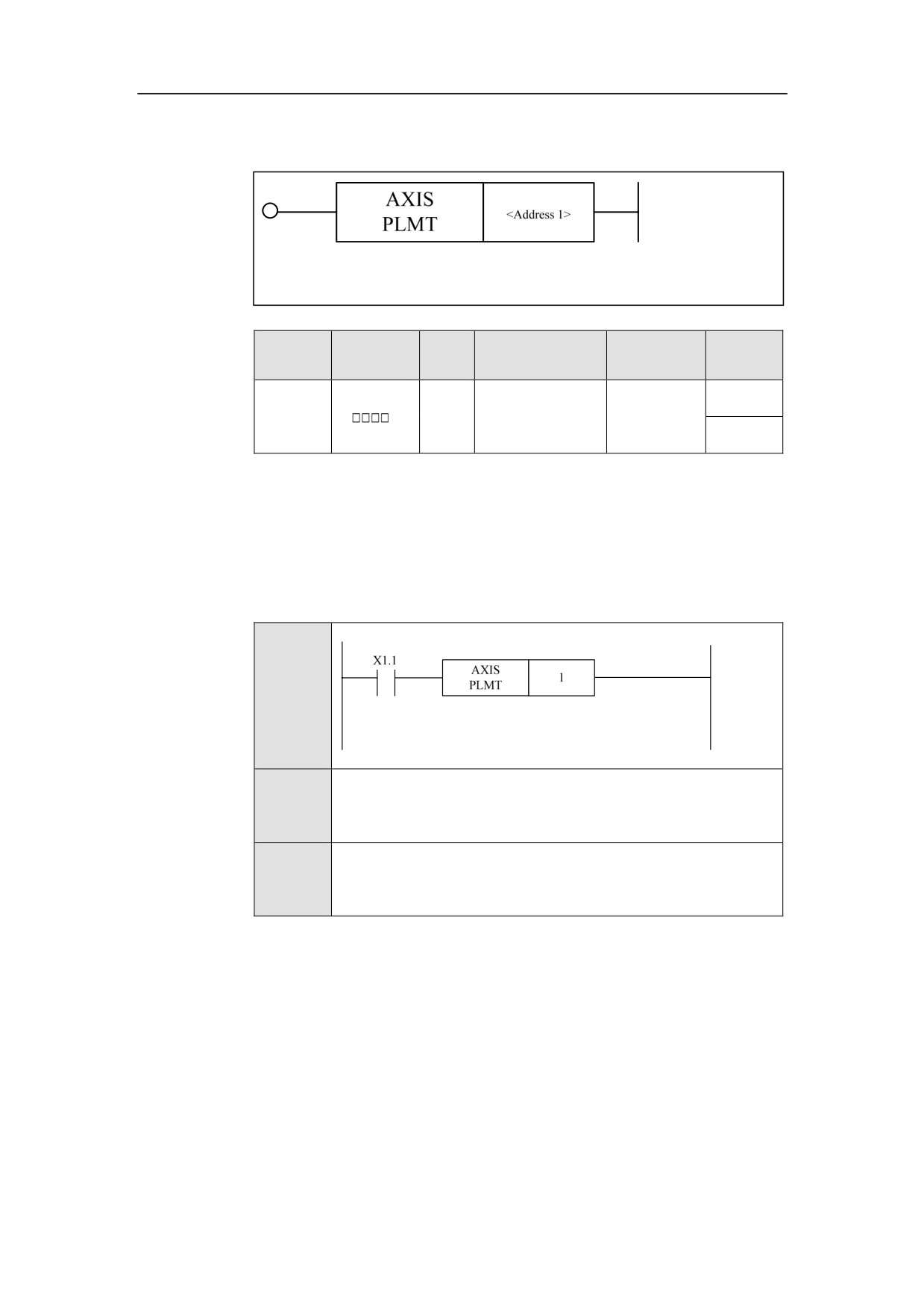
Block Switch in Positive Limit Direction AXISPLMT
Format
Paramet
Parameter
Data
Properti
Storage area
Explanation
er
form
type
es
Pre √
<Addres
INT
Constant
s 1>
Post ×
Function
The positive limit direction of the axis.
Parameter
Parameter 1: axis number.
Example
Ladder
Diagram
Stateme
AXISPLMT 1
nt List
Descripti
X1.1 being effective represents the positive limit direction of the
on
axis 1.
228
HNC-8-PLC Component specification
6. Extended function module
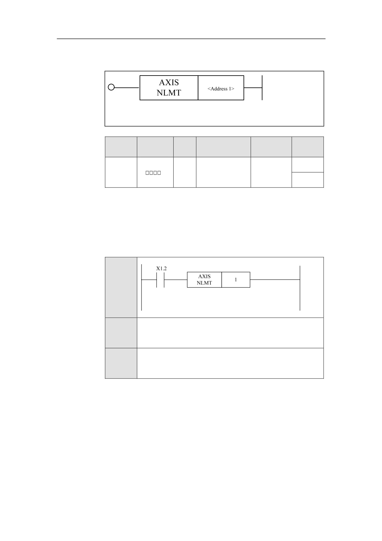
Block Switch in Negative Limit Direction AXISNLMT
Format
Paramet
Parameter
Data
Properti
Storage area
Explanation
er
form
type
es
Pre √
<Addres
INT
Constant
s 1>
Post ×
Function
The negative limit direction of the axis.
Parameter
Parameter 1: axis number.
Example
Ladder
Diagram
Stateme
AXISNLMT 1
nt List
Descripti
X1.2 being effective indicates the axis 1 meets the negative limit
on
point.
229
HNC-8-PLC Component specification
6. Extended function module
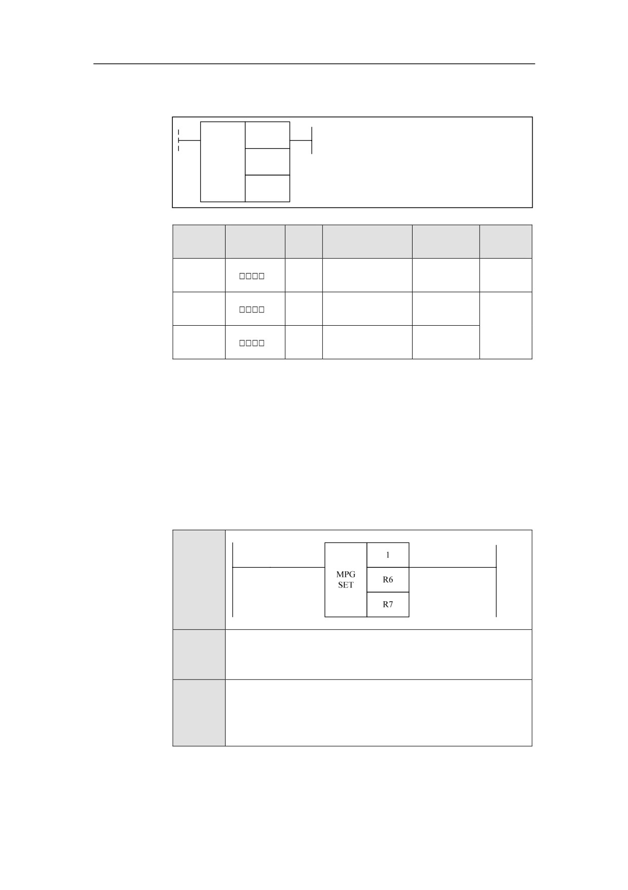
Handwheel MPGSET
Format
<Address 1>
MPG
<Address 2>
SET
<Address 3>
Paramet
Parameter
Data
Properti
Storage area
Explanation
er
form
type
es
<Addres
INT
Constant
Pre √
s 1>
<Addres
Constant, X, Y, F,
INT
s 2>
G, R, W, D, P, B
Post ×
<Addres
Constant, X, Y, F,
INT
s 3>
G, R, W, D, P, B
Function
To set handwheel.
Parameter
Parameter 1: handwheel number.
Parameter 2: axis number.
Parameter 3: override value.
Example
Ladder
Diagram
Stateme
MPGSET 1 R6 R7
nt List
Handwheel 1 gets its incremental value. The axis number selected
Descripti
by the handwheel
1 is stored in R6. Override value of the
on
handwheel 1 is stored in R7.
230
HNC-8-PLC Component specification
6. Extended function module
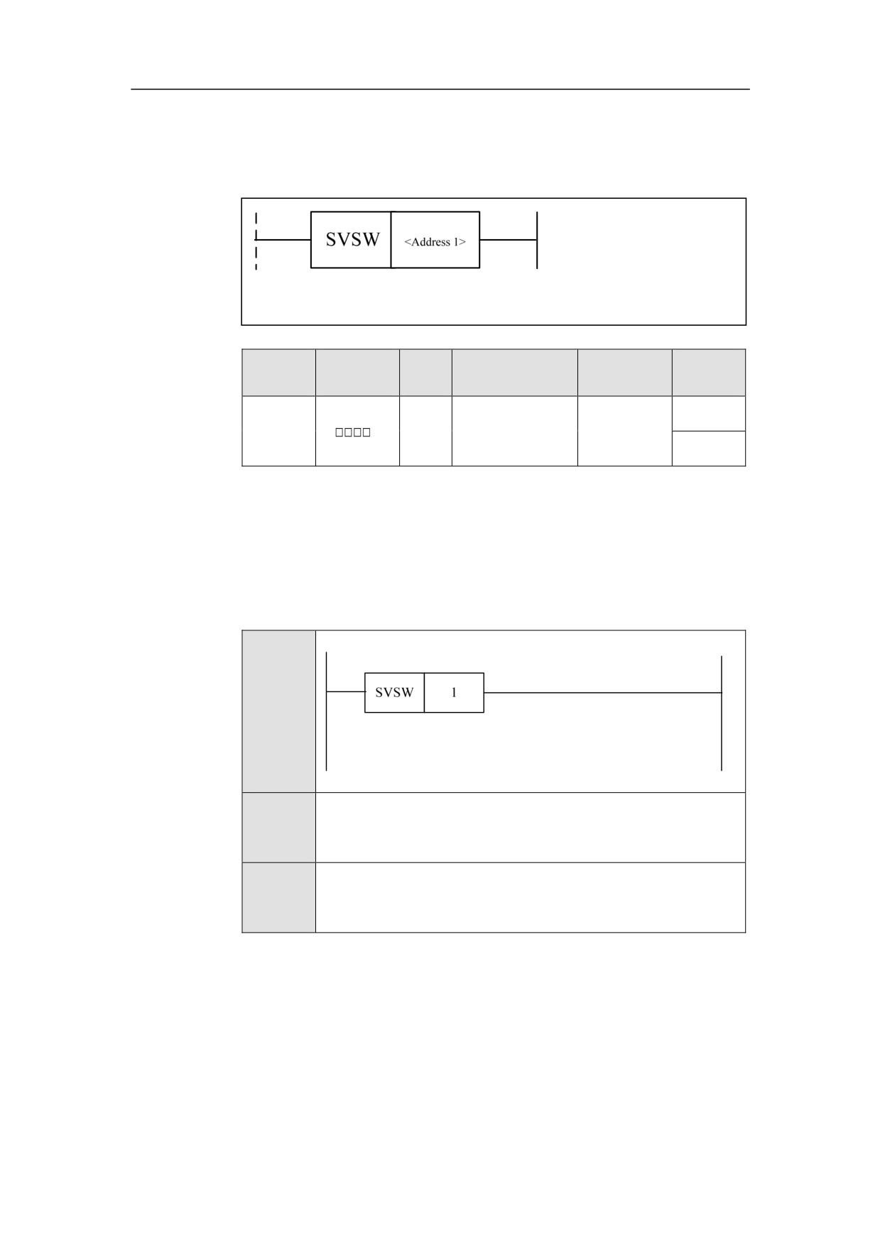
Servo Enable (Bus) SVSW
Format
Paramet
Parameter
Data
Properti
Storage area
Explanation
er
form
type
es
Pre ○
<Addres
INT
Constant
s 1>
Post ×
Function
Servo enable.
Parameter
Parameter 1: axis number.
Example
Ladder
Diagram
Stateme
SVSW 1
nt List
Descripti
Servo enable of the axis 1.
on
231
HNC-8-PLC Component specification
6. Extended function module
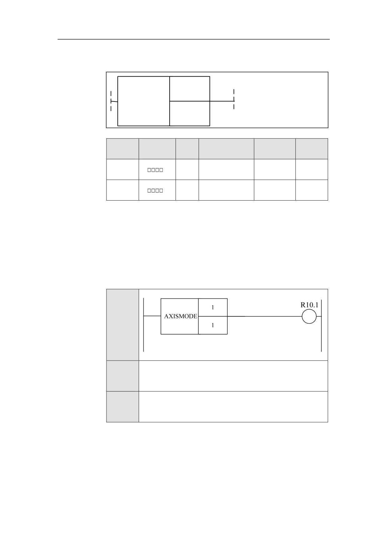
Axis Mode AXISMODE
Format
<Address 1>
AXIS
MODE
<Address 2>
Paramet
Parameter
Data
Properti
Storage area
Explanation
er
form
type
es
<Addres
INT
Constant
Pre ○
s 1>
<Addres
INT
Constant
Post ×
s 2>
Function
To select the working mode of the axis.
Parameter
Parameter 1: axis number.
Parameter 2: “0” is position, “1” is speed, and “2” is torque.
Example
Ladder
Diagram
Stateme
AXISMODE 1 1
nt List
Descripti
The working mode of axis 1 is set to the speed mode.
on
232
HNC-8-PLC Component specification
6. Extended function module
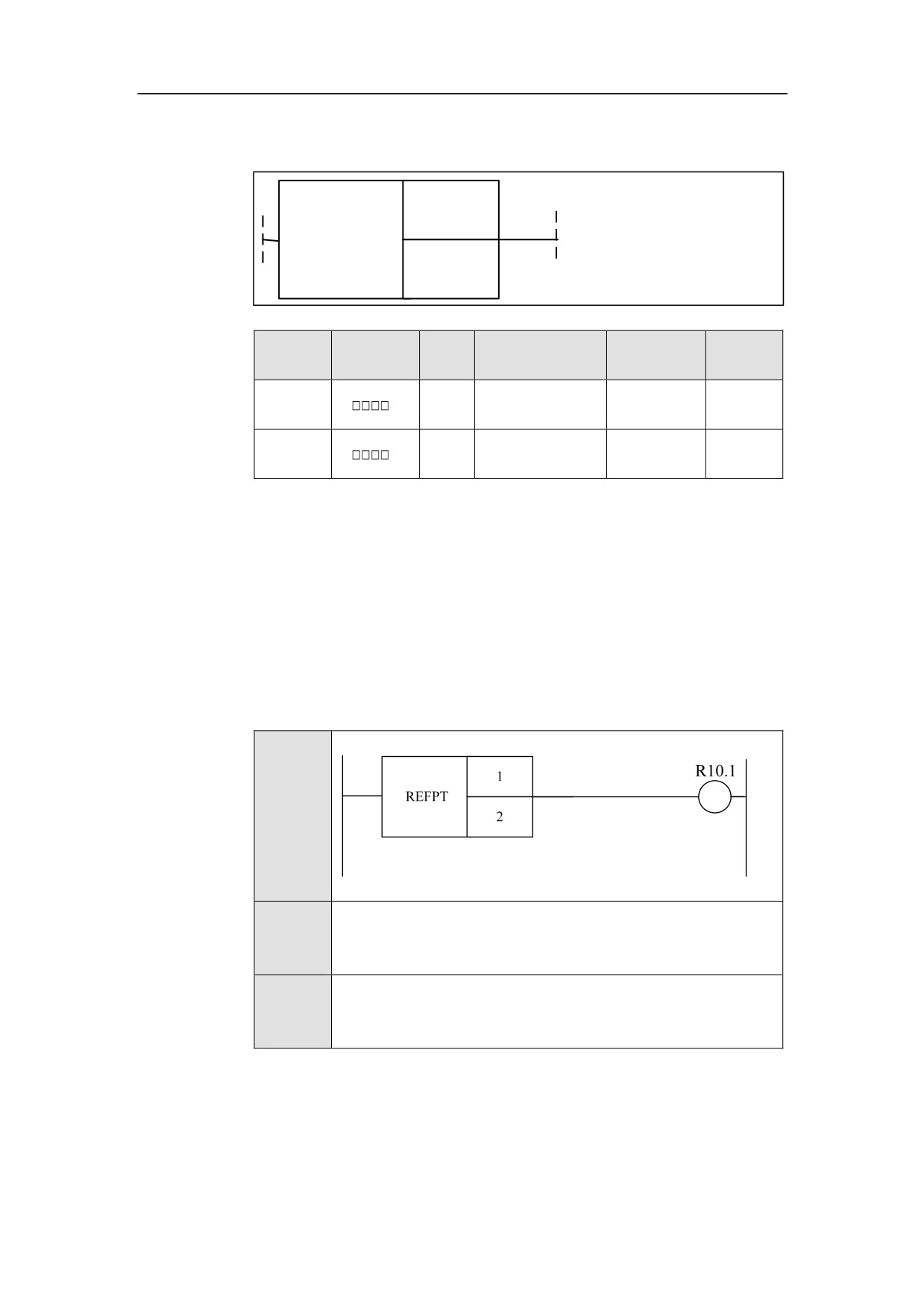
Axis Reference REFPT
Format
<Address 1>
REFPT
<Address 2>
Paramet
Parameter
Data
Properti
Storage area
Explanation
er
form
type
es
<Addres
INT
Constant
Pre ○
s 1>
<Addres
INT
Constant
Post √
s 2>
Function
To confirm the axis reference.
Parameter
Parameter 1: axis number.
Parameter 2: Parameter 2: “2” indicates that the second reference is valid, “3”
indicates that the third reference is valid, “4” indicates that the fifth reference is
valid.
Example
Ladder
Diagram
Stateme
REFPT 1 2
nt List
Descripti
The second reference of the axis 1 is valid, and R10.1 is output.
on
233