HNC-8 Numerical Control System Software. Maual of PLC Programming (V1.24) - page 6
HNC-8-PLC Component specification
4. Basic function module
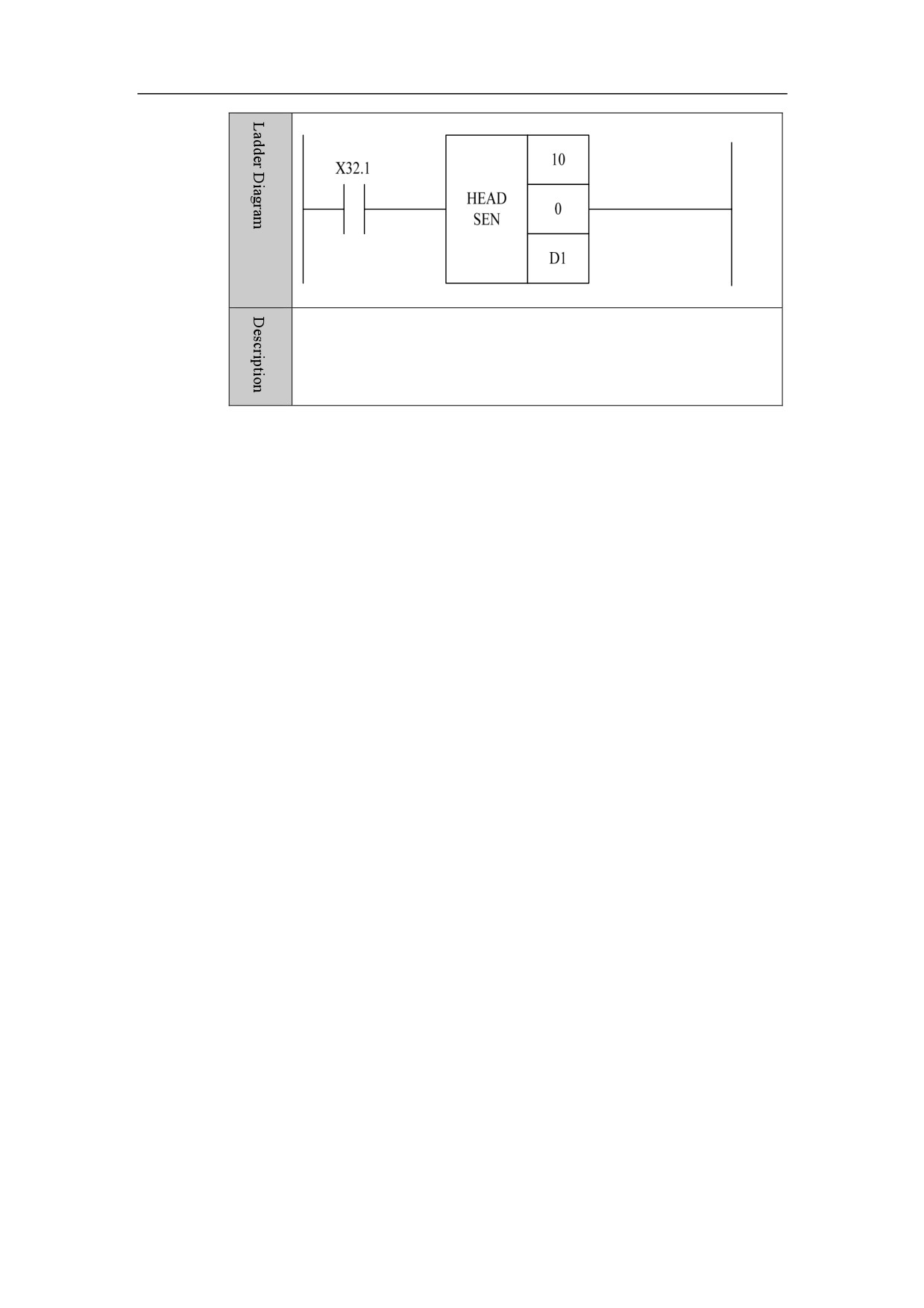
Example
When X32.1 is turned on, the temperature collection module starts to
count, and 10 temperature data is stored in the initial location given by
D1.
141
HNC-8-PLC Component specification
5. Status word and control word programming
Status
Word and Control Word
Programming
This chapter includes:
5.1 Introduction on Status Word and Control Word
5.2 Example of Status Word and Control Word Programming
142
HNC-8-PLC Component specification
5. Status word and control word programming
Introduction on Status Word and Control Word
Overview
The status word and control word are the most direct way of the interaction
between CNC and PLC. The status data of system can be obtained through the
status word, and you can write control word to change the system state. In the
system series 8, F represents status word with its property being read-only, G
represents control word with its property being read-write.
However, to limit the use of some key functions of system, some control words
are restricted, or are invisible to user. Please read following constraints of status
word and control word carefully.
Usage
restrictions
can be used
of
status
reserved for future extension
word and
control
cannot be used by user
word
Range of
Status words and control words can be divided into three types for each of its
application
function in the system. They all have serviceable range, refer to the configuration
manual for details.
Status words and control words of axis
Status words and control words of channel
Status words and control words of system
Symbol
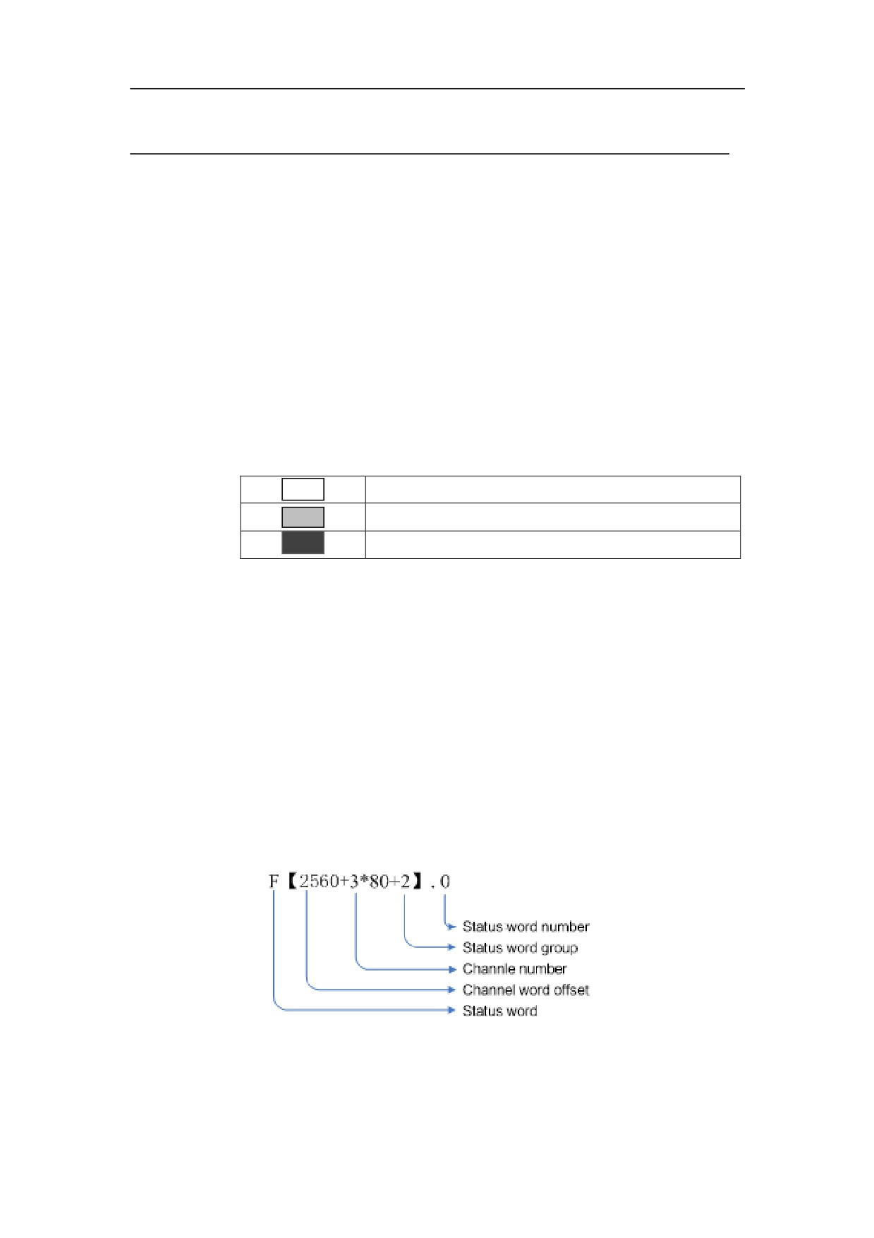
Take the words of channel as an example:
form
In this example, the format is channel 3, the second group of status word, and
143
HNC-8-PLC Component specification
5. Status word and control word programming
No.0 status word. 2560 is the offset of the channel status word. The format of
other types of words is similar.
144
HNC-8-PLC Component specification
5. Status word and control word programming
Axis Status Word
Overview
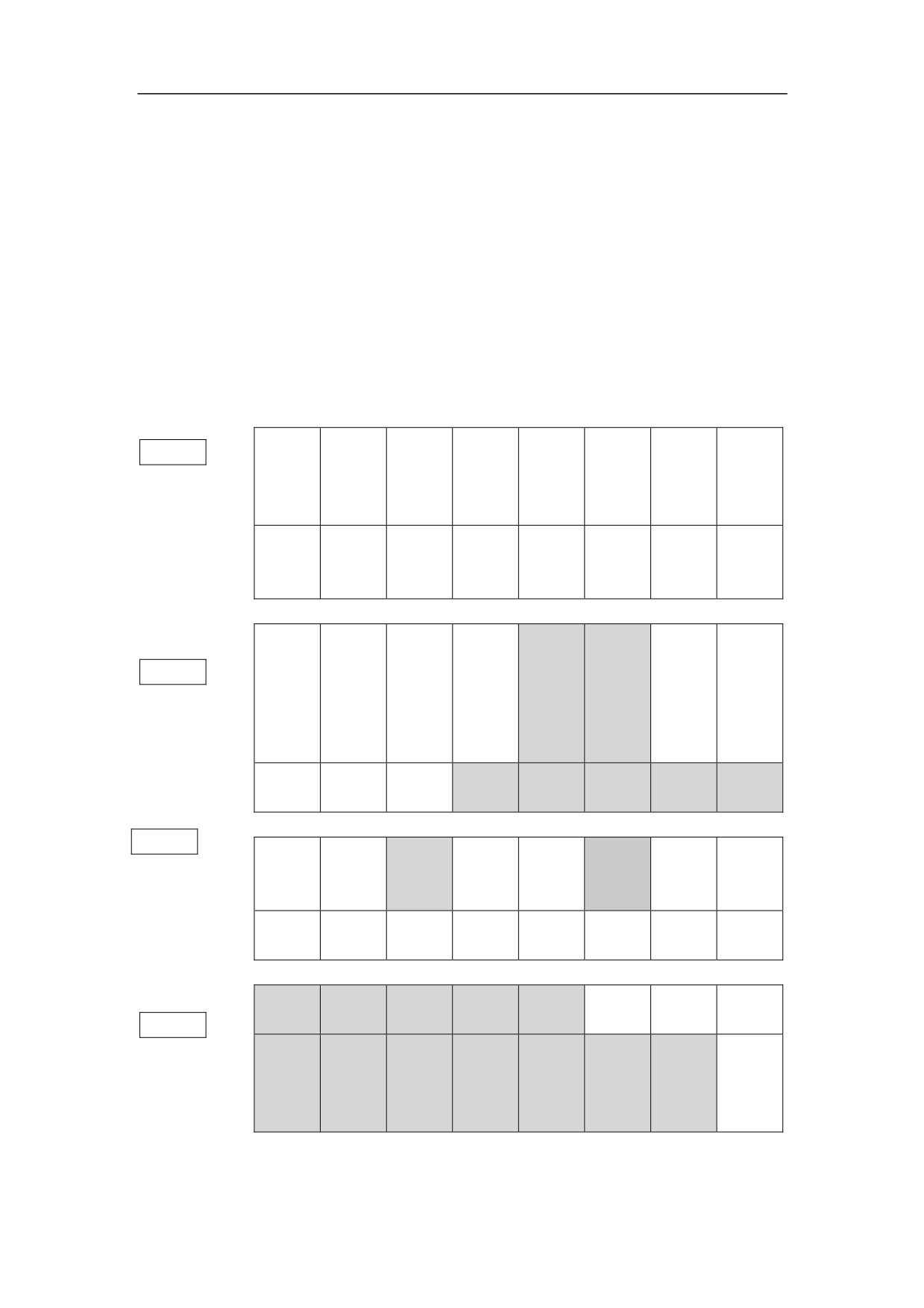
80 status words are configured for each axis. Each status word has a 16-bit byte.
The first row indicates the bits from 0 to 7, and the second row indicates the bits
from 8 to 15. The axis status words need to be used with the logical number
offset of axis.
Axis status
D7
D6
D5
D4
D3
D2
D1
D0
word
D15
D14
D13
D12
D11
D10
D9
D8
Return to
F0
Home
Return to
Subaxis
Subaxis
Subaxis
Home
the
Axis
completin
the first
follow
zero
home
failure
second
moving
g
reference
reference
Axis
The
Axis
The forth
The third
The first
Axis reset
Axis lock
parameter
second
overload
reference
reference
reference
ok
reference
Orientatio
F1
SPD
Spindle
n
Rapid
Spindle
PMC
Reserved
Reserved
arrival
stop
completin
feed
mode
enable
g
Index axis
Index
Index axis
Reserved
Reserved
Reserved
Reserved
Reserved
locking
position
unlocking
F2
Capture
Servo
Zero
Servo
2nd stage
Reserved
Reserved
Servo ready
the first Z
parameter
capture
home
home
pulse
Spindle
SPD
Gain
Z pulse
Torque
Speed
Position
Sv ready
stop
arrival
switch
capture
control
control
control
Servo
Servo
Normal
Reserved
Reserved
Reserved
Reserved
Reserved
prompt
alarm
servo
F3
Orientatio
n
Reserved
Reserved
Reserved
Reserved
Reserved
Reserved
Reserved
completin
g
145
HNC-8-PLC Component specification
5. Status word and control word programming
Details
【F0.0】During the axis movement, when the axis is moving, the value is 1;
when the axis is not moving, the value is 0.
【F0.1】The first step of returning home: when the axis is returning home
without meeting home block, the value is 1; otherwise, the value is 0.
【F0.2】The second step of returning home: when Z pulse is being looked for,
the value is 1; otherwise, the value is 0.
【F0.3】Unsuccessful homing: when the axis hasn’t returned to zero, the value is
1; otherwise, the value is 0.
【F0.4】Successful homing: When the axis has been to zero, the value is 1;
otherwise, the value is 0.
【F0.5】Subaxis is returning home.
【F0.6】Zero point of subaxis has been checked.
【F0.7】Following status of subaxis has been released.
【F0.8】Comfirm the first reference: when the axis is at the first reference point,
the value is 1; otherwise, the value is 0.
【F0.9】Comfirm the second reference: when the axis is at the second reference
point, the value is 1; otherwise, the value is 0.
【F0.10】Comfirm the third reference: when the axis is at the third reference
point, the value is 1; otherwise, the value is 0.
【F0.11】Comfirm the forth reference: when the axis is at the forth reference
point, the value is 1; otherwise, the value is 0.
【F0.13】Axis parameter is effective.
【F0.14】Axis has been locked.
【F0.15】Axis has been repositioned.
【F1.0】PMC control enabled. When PMC control has been enabled, the value is
1; otherwise, the value is 0.
【F1.1】Feed spindle mode. 1 is position mode, and 0 is speed mode.
【F1.5】Orientation of feed spindle has been finished.
146
HNC-8-PLC Component specification
5. Status word and control word programming
【F1.6】Feed spindle is at zero speed.
【F1.7】Feed spindle speed arrival.
【F1.13】Index axis is unlocked. 1 indicates that system notifies PLC to unlock
index axis. The index axis is enabled.
【F1.14】Index axis is at index position.
【F1.15】Index axis is locked. 1 indicates that system notifies PLC to lock index
axis. The index axis is disabled.
【F2.0】When Z pulse is captured once during homing of axis, the value is 1;
otherwise, the value is 0.
【F2.1】When servo ready flag is 0, servo can receive incremental data.
【F2.3】Capture Z pulse of the second encoder, which is mainly used for homing
of distance code grating scale.
【F2.4】When servo has been back to zero, the output is 1.
【F2.6】Zero capture, which is mainly usded for spindle. When spindle meets the
first Z pulse at rotating time, set the value to 1. In the event of CS switching, the
value nees to be set to 1.
【F2.7】Servo parameter switch. 0: default parameter. 1: switch to the second set
of parameter.
【F2.8】When bus servo is ready, the value is 1; otherwise, the value is 0.
【F2.9】When servo is in position control mode, the value is 1; otherwise, the
value is 0.
【F2.10】When servo is in speed control mode, the value is 1; otherwise, the
value is 0.
【F2.11】When servo is in torque control mode, the value is 1; otherwise, the
value is 0.
【F2.12】When Z pulse is encountered, the value is 1; otherwise, the value is 0.
【F2.13】
【F2.14】When the spindle speed reaches, the value is 1, otherwise, the value is
0.
【F2.15】Spinde stop: when spindle stops, the value is 1; otherwise, the value is
0.
【F3.0】When servo is normal, the value is 1.
【F3.1】When servo alarms, the value is1.
【F3.2】When servo prompts, the value is 1.
【F3.8】Spindle orientation is completed After spindle orientation is set, spindle
starts directing. After the directing is completed, servo returns the signal of
completing spindle orientation, and the value is 1; otherwise, the value is 0.
【F4】Number of channel which the axis belongs to. (Channel number is in
decimal.)
【F5】Number of driven axises which are guided. (Number of driven axises is in
decimal.)
【F[6/7]】Real-time output command increment, motor coordinate.
147
HNC-8-PLC Component specification
5. Status word and control word programming
【F[8/9/10/11]】Real-time output command position, motor coordinate. (metric
system)
【F[12/13/14/15]】Output command pulse position, unit: pulse.
【F[16/17]】Command pulse per cycle. Number of command pulses which is
sent to servo each cycle.
【F[18/19]】Output command torque.
【F[20/21/22/23]】Actual feedback position of encoder 1. (metric system)
【F[24/25/26/27]】Actual feedback position of encoder 2. (metric system)
【F[28/29/30/31]】Command position of machine. (metric system)
【F[32/33/34/35]】Actual position of machine. (metric system)
【F[36/37]】Axis alarm
【F36.2】Plus software limit switch reached.
【F36.3】Minus software limit switch reached
【F36.4】Actual speed is overspeed.
【F36.6】Overspeed
【F36.7】Super acceleration.
【F36.8】Z pulse cannot be found.
【F36.9】Connection has been aborted.
【F36.10】Not referenced.
【F36.11】Sync position out-of-tolerance
【F36.12】Slave axis zero check is aborted
【F36.13】Sync speed out-of-tolerance
【F37.0】Plus software limit exceeded.
【F37.2】Minus software limit exceeded.
【F37.2】Acceleration does not match maximum speed.
【F[38/39]】Axis prompt
【F38.0】Max compensation ratio exceeded.
【F38.1】Max compensation exceeded.
【F38.2】Zero offset parameter is too small.
【F38.4】Software limit is too large.
【F38.5】The second software limit is too large.
【F38.6】Absolute encoder cycle digits are illegal.
【F38.7】Position overflow.
【F38.8】Target is outside plus software limit.
【F38.9】Target is outside minus software limit.
【F38.10】Mask angle of Z pulse needs to be adjusted.
【F38.11】Reference position needs to be adjusted.
【F38.12】Tracking error is too large.
【F[70]】Current axis mode.
148
HNC-8-PLC Component specification
5. Status word and control word programming
149
HNC-8-PLC Component specification
5. Status word and control word programming
Axis Control Word
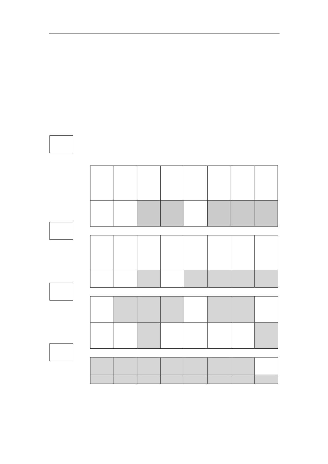
80 control words are configured for each axis. Each control word has a16-bit
Overview
byte. The first row indicates the bits from 0 to 7, and the second row indicates
the bits from 8 to 15. The axis contorl words need to be used with the logical
number offset of axis.
Axis
control
word
D7
D6
D5
D4
D3
D2
D1
D0
G0
D15
D14
D13
D12
D11
D10
D9
D8
Axis
Axis lock
Home
Home
No axis
No axis
Negative
Positive
enable
block
start
motion in
motion in
limit
limit
negative
positive
direction
direction
Axis reset
Compens
Reserved
Reserved
Subaxis
Reserved
Reserved
Reserved
ation
follow
expansion
G1
*SP
*SP
*SP
*SP Jog
Expand
The
Relative
Absolute
rotation
rotation
orientatio
software
second
pmc
pmc
CCW
CW
n
limit
software
motion
motion
limit
Response
Response
Reserved
CS
Reserved
Reserved
Reserved
Reserved
locking
unlocking
response
G2
Servo
Reserved
Reserved
Reserved
Capture Z
Capture Z
Parameter
pulse of
Reserved
Reserved
pulse
encoder 2
Spindle
Directiona
Reserved
Spindle
Torque
Speed
Position
Servo
current-li
l
orientation
control
control
control
gain
miting
gear-shift
G3
Reserved
Reserved
Reserved
Reserved
Reserved
Reserved
Reserved
Servo
enable
Reserved
Reserved
Reserved
Reserved
Reserved
Reserved
Reserved
Reserved
Details
150
HNC-8-PLC Component specification
5. Status word and control word programming
【G0.0】Positive limit switch of axis.
【G0.1】Negative limit switch of axis.
【G0.2】No axis movement in positive direction.
【G0.3】No axis movement in negative direction.
【G0.4】Set to start homing.
【G0.5】Set home block.
【G0.6】Set to lock the axis.
【G0.7】Set axis enable
【G0.11】Set to disable function of subaxis following
【G0.14】Compensation expansion
【G0.15】Single-axis reset
【G1.0】Absolute PMC axis motion is enabled.
【G1.1】Relative PMC axis motion is enabled.
【G1.2】The second software limit is enabled.
【G1.3】Extension software limit is enabled.
【G1.4】Feed-spindle Jog.
【G1.5】Feed-spindle orientation.
【G1.6】Feed -spindle rotates in clockwise direction.
【G1.7】Feed -spindle rotates in counter clockwise direction.
【G1.12】Response flag of PLC to spindle C/S switch.
【G1.14】Response flag of PLC to signal of unlocking index axis.
【G1.15】Response flag of PLC to signal of locking index axis.
【G2.0】Z pulse flag. (when motor is at the position of Z pulse, this flag is 1.)
【G2.1】Wait for zero pulse
【G2.2】Turn off function of searching zero pulse.
【G2.3】Capture zero pulse of the second encoder.
【G2.7】 Servo parameter switch. 0: Defaul parameter, 1: switch to the second
set of parameter.
【G2.8】Servo gain switch.
【G2.9】Switch to position control mode.
151
HNC-8-PLC Component specification
5. Status word and control word programming
【G2.10】Switch to speed control mode.
【G2.11】Switch to torque control mode.
【G2.12】Spindle orientation start.
【G2.14】Directional gear-shift of spindle.
【G2.15】Spindle current-limiting
【G3.0】Servo enable switch.
【G4】Axis jog flag. When the axis is manual, or returning to zero, or the spindle
is rotating, this flag is effective.
【G5】Increment flag of axis. When axis is moving incrementally, this flag is
effective.
【G[6/7]】Jog speed. 0: stop; 1: Jog speed in paramter; 2: Rapid traverse speed in
parameter; >2: Self-defined speed.
【G8】Incremental rate.
【G9】Handwheel rate.
【G[10/11]】handwheel pulse.
【G[12/13/14/15]】Axis feedback position, unit: pulse
【G[16/17/18/19]】Axis feedback position 2, unit: pulse
【 G[20/21] 】 Actual speed of axis, unit: pulse. Actual axis-speed is the
incremental value per cycle of the actual feedback position of axis (G12-G15).
【G[22/23]】Actual speed 2 of axis
【G[24/25]】Actual torque of axis
【G[26/27]】Tracking error. (Tracking error of axis is the difference between the
actual axis feedback position
(G12-G15) and the axis command position
(F12-F15).)
【G[28/29/30/31]】Counter value of encoder 1
【G[32/33/34/35]】Counter value of encoder 2
【G[36/37]】Real-time compensation value.
【G[38/39]】Sample timestamp
【G[40/41/42/43]】Latch position 1 (when the first encoder has z pulse, the
current position is latched, which is used for G31 or distance code homing.
【G[44/45/46/47]】Latch position 1 (when the second encoder has z pulse, the
current position is latched, which is used for G31 or distance code homing.
152
HNC-8-PLC Component specification
5. Status word and control word programming
【G[48/49/50/51]】Target position of absolute movement for PMC axis.
【G[52/53/54/55]】Incremental movement of PMC axis
【G[56/57]】Servo alarm code.
【G[58/59]】Servo prompt code.
【G60】(2 is handwheel interruption, and 103 is PMC mode)
【G61】Override value of PMC axis.
【G62.0】PMC axis stop.
【G62.1】Zero handwheel interruption.
【G62.2】Turn on function of tangent following.
【G62.4】Index axis switch.
【G62.5】When coupling of driven axis is restored, synchronize the position of
synchronization axis.
【G62.8】Spindle control, write actual rotation speed to instruction.
【G62.9】Start spindle rotation speed of gear shift.
【G64】Current axis gear.
【G66/67】Gear shift of spindle.
【G68/69】Z pulse position.
【G70/71】Z pulse interval 1.
【G72/73】Z pulse interval 2.
【G74】Gear shift of spindle.
【G78/79】Sample data of servo
153
HNC-8-PLC Component specification
5. Status word and control word programming
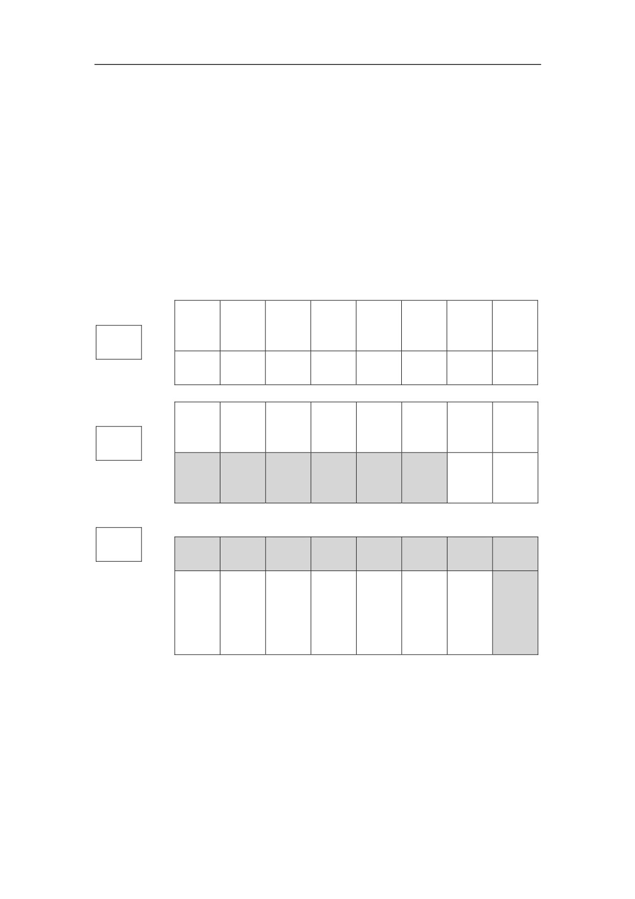
Channel Status Word
Overview
80 control words are configured for each channel. Each control word has a 16-bit
byte. The first row indicates the bits from 0 to 7, and the second row indicates
the bits from 8 to 15. The axis contorl words need to be used with the logical
number offset of channel.
Axis status
D7
D6
D5
D4
D3
D2
D1
D0
word
D15
D14
D13
D12
D11
D10
D9
D8
User
Cycle
interventi
非自动时运动
Feedhold
Mode #3
Mode #2
Mode #1
Mode #0
start
F2560
on
Search Z
Suspend
Verify
Resetting
Rest flag
reserved
Cut thread
Cutting
pulse
request
state
Interrupti
Wait for
Interrupti
Procedure
Program
Program
reserved
reserved
on
comletion
on skip
complete
start
select
F2561
complete
Non-null
Non-null
reserved
reserved
reserved
reserved
reserved
reserved
completio
instructio
n
n
F2562
reserved
reserved
reserved
reserved
reserved
reserved
reserved
reserved
Spindle is
4S
3S
2S
1S
at
Index
Tool
instructio
instructio
instructio
instructio
constant
instructio
reserved
offset flag
n
n
n
n
linear
n
speed
Details
【F2560.0 ~F2560.3】To get mode
0: Reset mode
1: Auto mode
2: Manual mode
3: Increment mode
4: Handwheel mode
5: Home mode
6: PMC mode
7: Single block mode
8: MDI mode
154
HNC-8-PLC Component specification
5. Status word and control word programming
【F2560.4】Feedhold: channel is in state of feedhold.
【F2560.5】Cycle start:channel is in state of cycle start.
【F2560.6】Axis moves in non-auto mode.
【F2560.7】User movement is interfering.
【F2560.8】Cutting.
【F2560.9】Thread-cutting: channel is in state of cutting thread, and feedhold is
not allowed.
【F2560.11】Verify state.
【F2560.12】Channel reset: in the event of channel reset or reset button on panel
being pressed, channel reset is effective, until channel reset response is set.
【F2560.13】Suspend request.
【F2560.14】Channel is resetting.
【F2560.15】When axis is returning home to look for Z pulse, switching mode is
not allowed.
【F2561.0】Program is selected, which is set by interpreter.
【F2561.1】Program start, which is set by channel control.
【F2561.2】Program is completed, which is set by channel control.
【F2561.3】Interrupt instruction G28/G31 is completed.
【F2561.4】Skip interrupt instruction.
【F2561.5】Wait for completing instruction.
【F2561.8】There are non-empty instruction flags in channel.
【F2561.9】Non-empty instruction flag is completed in channel.
【F2562.9】Tool offset mark [tool offset number is in T instruction]
【F2562.10】PLC index instruction flag.
【F2562.11】Spindle is at constant linear speed.
【F2562.12】The first S instruction.
【F2562.13】The second S instruction.
【F2562.14】The third S instruction.
【F2562.15】The forth S instruction.
【F2569】Tool offset number, which is in T instruction.
155
HNC-8-PLC Component specification
5. Status word and control word programming
【F[2570/2571】The first S instruction. Unit: 0.001 revolution/minute.
【F[2572/2573】The second S instruction. Unit: 0.001 revolution/minute.
【F[2574/2575】The third S instruction. Unit: 0.001 revolution/minute.
【F[2576/2577】The forth S instruction. Unit: 0.001 revolution/minute.
【F2578/79】G31 number which is currently waiting signal.
【F2580】Currently running coordinate system.
【F[2581/2589]】Axis numbers of nine axises in channel
【F[2590/2593]】Axis number of the forth spindle in channel.
【F[2594/2595]】Alarm code of syntax error.
【F[2596/2599]】Channel alarm code.
【F[2600/2603]】Channel prompt number.
【F[2604/2607]】User output.
【F[2608/2615]】M codes which run in channel, with a maximum of 8.
【F2616】T instruction in channel. When T code is executing in channel, the
value of T code is in register; otherwise, the output is 1.
【F2617】B instruction in channel. B axis in boring machine is executed by PLC,
and indexing is executed by B instruction.
【F2632】Number of tool which is alarmed for the maximum life span being
reached.
【F2636.0】Channel is resetting.
【F2632.1】Program has been stopped exactly.
【F2632.2】Flag of inclined axis
【F2632.3】Interpolation instruction runs in channel.
【F2632.4】Flag of spindle synchronization.
【F2632.5】Handwheel feed direction.
【F2637.0】Subprogram process start.
【F2637.1】Subprogram waits for feedhold, and saves breakpoint.
【F2637.2】Break point flag.
【F2637.3】Start to load subprogram.
【F2637.4】Complete loading.
【F2637.5】Start running.
156
HNC-8-PLC Component specification
5. Status word and control word programming
【F2637.6】Complete running.
【F2637.7】Breakpoint has been restored.
【F2637.8】Process ends.
【F2637.9】Process error
【F2637.10】Process reset.
【F2637.11】Process waits for interpreter reset to complete.
【F2638.0】Tool life-span manage - cumulative times of tool changing
157

HNC-8-PLC Component specification
5. Status word and control word programming
Channel Control Word
Overview
80 control words are configured for each channel. Each control word has a 16-bit
byte. The first row indicates the bits from 0 to 7, and the second row indicates
the bits from 8 to 15. The axis contorl words need to be used with the logical
number offset of channe
Axis
D7
D6
D5
D4
D3
D2
D1
D0
control
D15
D14
D13
D12
D11
D10
D9
D8
word
Measure
ment
Cycle
Work
Work
Work
Work
Dry run
Feedhold
interrupti
start
mode
mode
mode
mode
G2560
on
Data
Clear
Emergenc
Panel
Reset
Data save
Reset
Verify
revovery
cache
y stop
reset
response
Data
Arbitrary
Explanati
Selection
Skip
Interpreter
Rerun
Rerun 2
G2561
recovery
row
on reset
stop
block flag
startup
Handwhe
Program
External
el
User
Explanati
Reserved
modificati
Reserved
interruptio
Reserved
interruptio
motion
on save
on
n
n
G2562
Reserved
Reserved
Reserved
Reserved
Reserved
Reserved
Reserved
Reserved
Rotation
Reserved
Reserved
No
Speed
Reserved
Reserved
speed
MST lock
spindle
check
arrival
G2620
Panel
Handwhe
Home
Single
PMC
Increment
Manual
Auto
enable
el
reference
block
Rapid
Reserved
Reserved
Reserved
Reserved
Reserved
Incremental rate
traverse
Handwheel 1
Handwheel 0
G2621
Handwhe
Hanwheel 0 rate
Reserved
Reserved
Reserved
el 1
Hanwheel 1 rate
enable
158

HNC-8-PLC Component specification
5. Status word and control word programming
Axis 7+
Axis 6+
Axis 5+
Axis 4+
Axis 3+
Axis 2+
Axis 1+
Axis 0+
G2622
Axis 8+
Reserved
Reserved
Reserved
Reserved
Reserved
Reserved
Reserved
Axis 7-
Axis 6-
Axis 5-
Axis 4-
Axis 3-
Axis 2-
Axis 1-
Axis 0-
Axis 8-
G2623
Reserved
Reserved
Reserved
Reserved
Reserved
Reserved
Reserved
Details
【G2560.0/1/2/3】Work mode. 0: reset mode, 1: auto mode, 2: manual mode, 3:
increment mode, 4: handwheel mode.
【G2560.4】Feedhold: Set feedhold in channel.
【G2560.5】Cycle start: set cycle start in channel.
【G2560.6】Dry run: set to dry run in channel.
【G2560.7】Mearsure interruption flag. When this flag is set to 1, system
interrupts ongoing G31 instruction. It is used with G2582.
【G2560.8】Verify
【G2560.9】PLC reset response: when PLC has been reset, set this flag to 1.
【G2560.10】Panel reset flag. Through deteting this flag, PLC discover whether
the system is resetting.
【G2560.11】Emergency stop flag. This flag is set for emergency stop of
machine.
【G2560.12】Flag of channel buffering clear.
【G2560.13】This flag is set for resetting machine.
【G2560.14】Flag of channel data recovery.
【G2560.15】Channle data save.
【G2561.0】Flag of interpreter startup.
【G2561.1】Flag of the second step of program rerun.
【G2561.2】Flag of skipping block. When this flag is set to 1, system skips
block.
【G2561.3】Selection stop flag. When this flag is set to 1, system performs
159
HNC-8-PLC Component specification
5. Status word and control word programming
selection stop.
【G2561.4】Flag of interpreter reset.
【G2561.5】Flag of program rerun.
【G2561.6】Flag of MDI resetting to program header
【G2561.7】Flag of interpreter data recovery.
【G2561.8】Flag of interpreter data save.
【G2561.9】Exact-stop check.
【G2561.10】Flag of user motion control.
【G2561.11】Flag of external interruption.
【G2561.12】Turn on handwheel interruption.
【G2561.14】Flag of program modification.
【G2561.15】Coordinate of workpiece or tool changes, require to re-explain.
【G2562.0】S instruction response word of No.1 spindle.
【G2562.1】S instruction response word of No.2 spindle.
【G2562.2】S instruction response word of No.3 spindle.
【G2562.3】S instruction response word of No.4 spindle.
【G2562.8】Feed direction of trial cut by handwheel. 0 is moving forward, 1 is
retracting.
【G2562.10】Spindle speed check.
【G2560.10】Flag of panel reset. PLC discovers whether system is resetting by
detecting this flag.
【G2560.11】Emergency stop, to set channel of emergency stop.
【G2562.11】MST lock.
【G2562.12】Spindle is not started.
【G2562.13】Spindle speed doesn’t reach.
【G2562.14】Following start.
【G2562.15】Trial cut by handwheel. Use handwheel rate.
【G2563】T instruction.
【G2564】Feedrate override.
【G2565】Rapid traverse override.
160
HNC-8-PLC Component specification
5. Status word and control word programming
【G2566/67/68/69】Spindle overrise. Overrise of four spindles in channel.
【G2570/71/72/73/74/75/76/77】Spindle output instruction, output instructions
of four spindles in channel. After obtaining spindle rotation speed
(F2570-F2577), PLC calculates spindle override, and outputs spindle instruction.
In servo spindle, the output is spindle rotation, and in converter spindle, the
output is DA value.
【G2578】F2578.1 imaginery axis control.
【G2579】Machined-part counts
161
HNC-8-PLC Component specification
5. Status word and control word programming
【G2580/81】Mask in protected area.
【G2582】G31 number. When G31 execution is interrupted, the number of
interrupted G31.
【G2584/85/86/87】User bit input
【G2588~2607】User value input.
【G2608~2615】M code response of channel. When PLC is not executing M
code, set to -1; when PLC is executing M code, set to -2; when PLC has
executed M code, set to the currently executed M code.
【G2616】T code response of channel. When PLC has executed T code, set to
the currently executed T code; otherwise, set to -1.
【G2617】Tangent following of tool.
【G2636.0】Channel reset (PLC sets register, and notifies HMI to reset channel.)
【G2636.3】IRQ control
162
HNC-8-PLC Component specification
5. Status word and control word programming
【G2636.4】No channel reset【Reset button is invalid】
【G2636.5】Life timing/counting pause.
【G2560.15】Channel data save
【G2561.0】Interpreter start.
【G2637】Subprogram calling start.
【G2638】Counting of tool changing.
【G2970】Flag of system activity channel.
【G2978】System activity control channel
【G2980~2989】Control word of handwheel【previous axis selection】
【G2990~2999】Display output of handwheel.
【G3010~3025】External alarm of PLC (External alarm of PLC, and 8*32=256
external alarms exist concurrently).
【G3040~3055】External event of PLC (external event of PLC, and 8*32=256
external events exist concurrently).
【G3056~3070】External reminder of PLC (external reminder of PLC, and
8*32=256 external events exist concurrently).
【G3080~3099】Temperature sensor value.
163
HNC-8-PLC Component specification
5. Status word and control word programming
Example of Status Word and Control Word
Programming
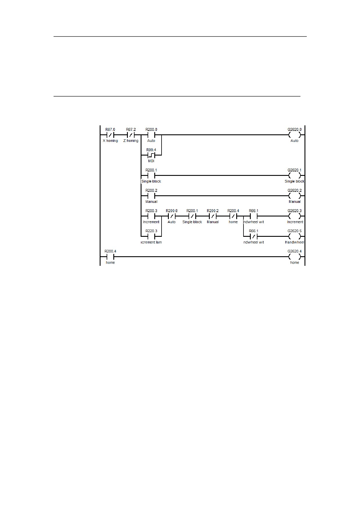
Work Pattern Setting
Example
Ladder
diagram
Function
Set the status in the working pattern of channel. When the axis is in the position
control mode, set the working pattern of the current channel to auto, single block,
manual, increment, handwheel or home.
164
HNC-8-PLC Component specification
5. Status word and control word programming
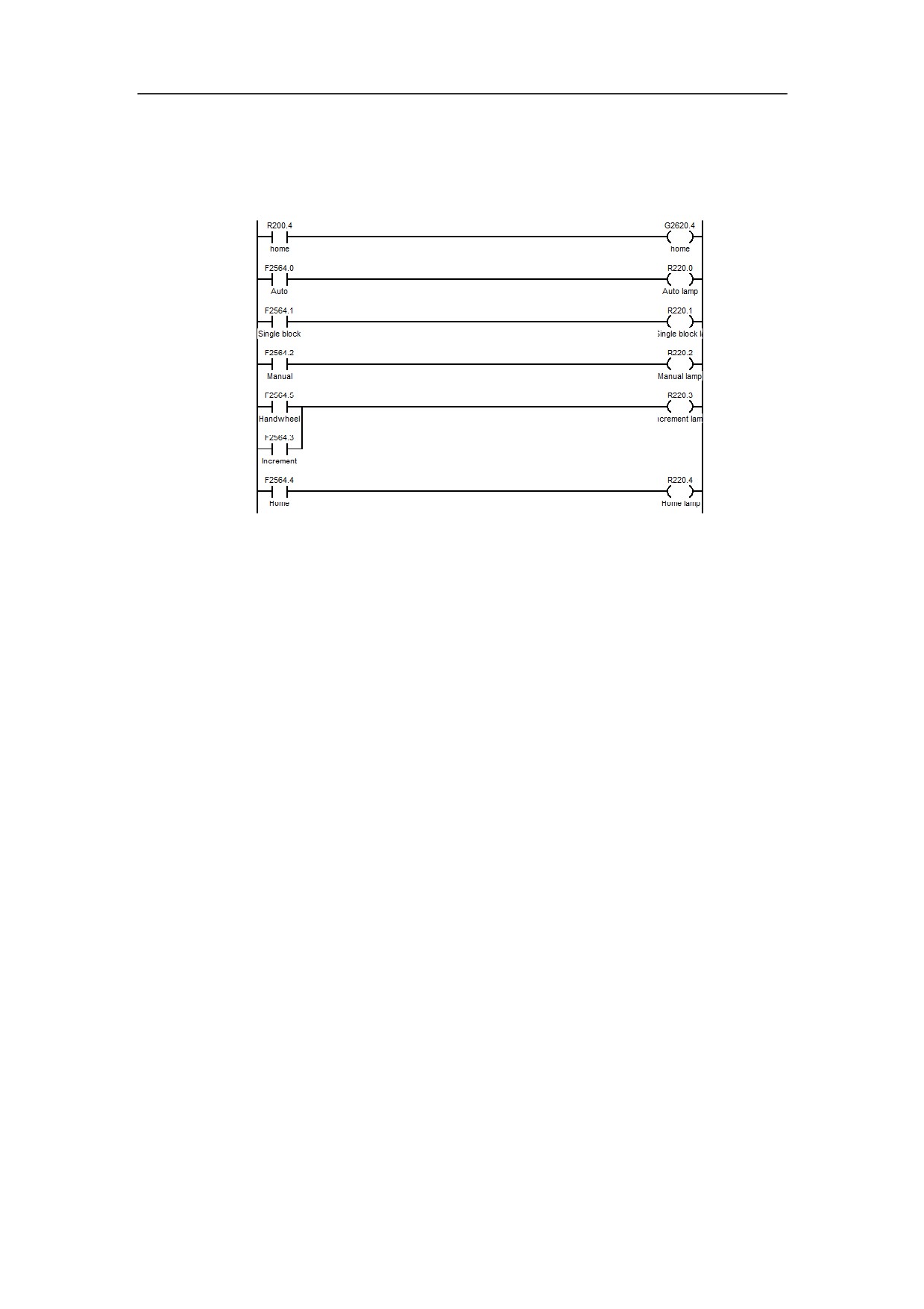
Work Pattern Getting
Example
Ladder
diagram
Function
Get the status in the working pattern of channel, which can be auto, single block,
manual, increment, handwheel or home.
165
HNC-8-PLC Component specification
5. Status word and control word programming
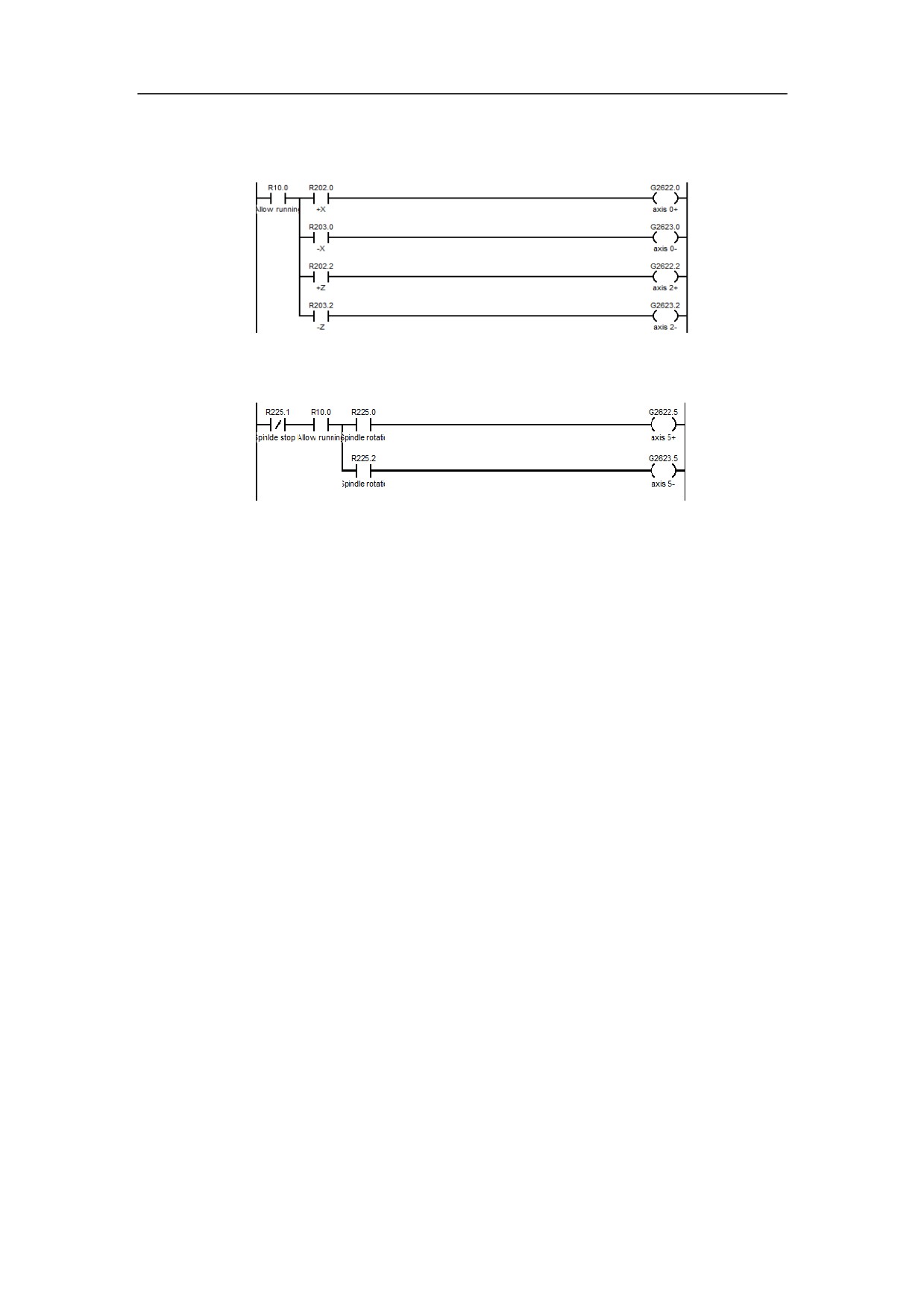
Control of Feed Axis and Spindle
Example
Ladder
diagram
Function
It is used to control the movement of feed axis, and the spindle rotation. Set the
current channel mode to manual mode, if you press Axis selection, and positive
or negative movement button, the moving status of the current axis will be set,
thus the axis will move; if you press spindle rotation (CW or CCW) button, the
rotation direction of the spindle will be set.
166
HNC-8-PLC Component specification
5. Status word and control word programming
Home
Example
Ladder
diagram
Function
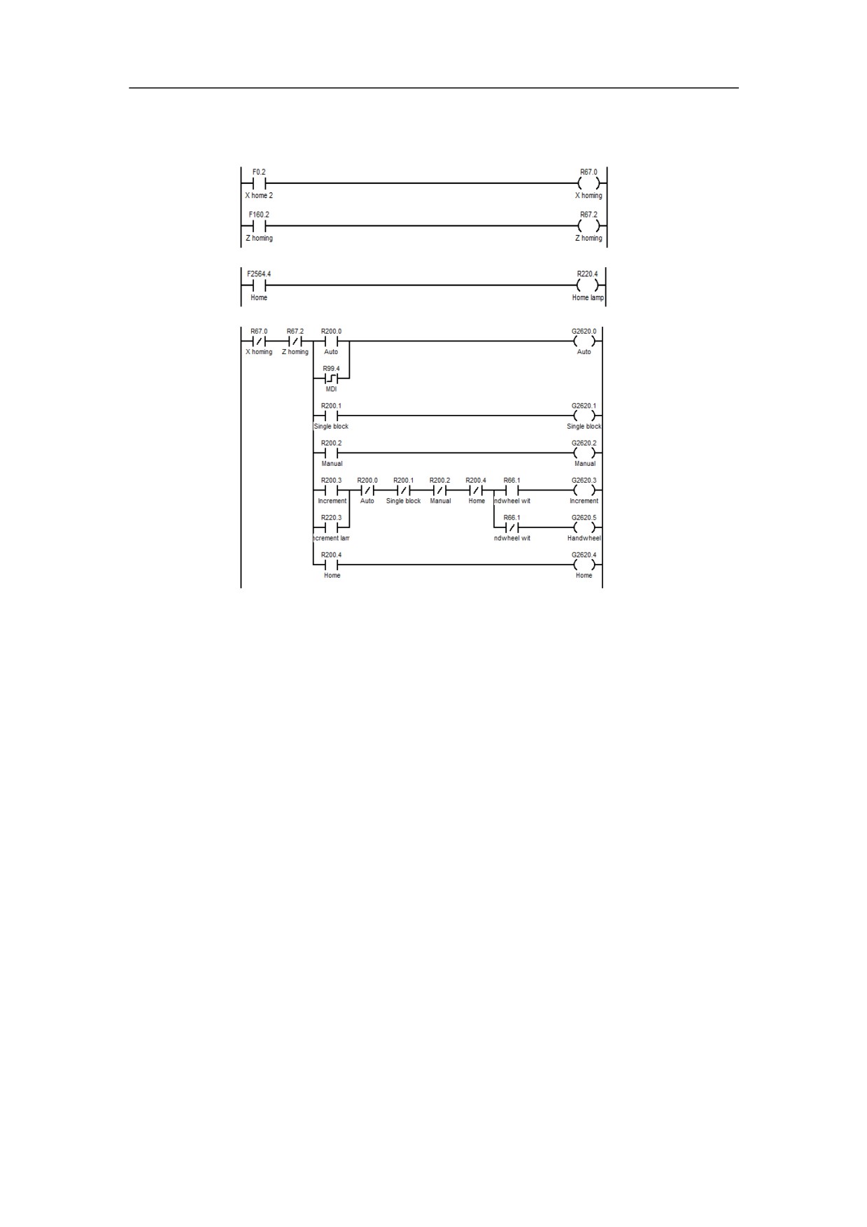
Obtain whether the current channel is returning home, through the status register.
During the process of meeting the home block, which is the first home process,
switching to other statuses is allowed; During the process of researching Z pulse,
which is the second home process, switching to other statuses is not allowed.
167
HNC-8-PLC Component specification
5. Status word and control word programming
Incremental Rate Override
Example
Ladder
diagram
Function
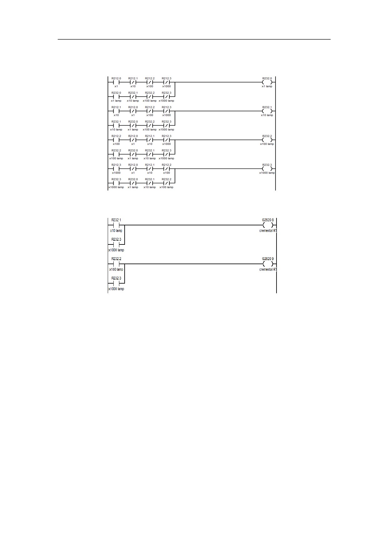
Incremental rate consumes two bits. 00 represents x1, 01 represents x10, 10
represents x100, and 11 represents x1000. The axis movement is controlled by
the setting of above axis register.
168
HNC-8-PLC Component specification
5. Status word and control word programming
Cycle Start and Feed Hold
Example
Ladder
diagram
Function
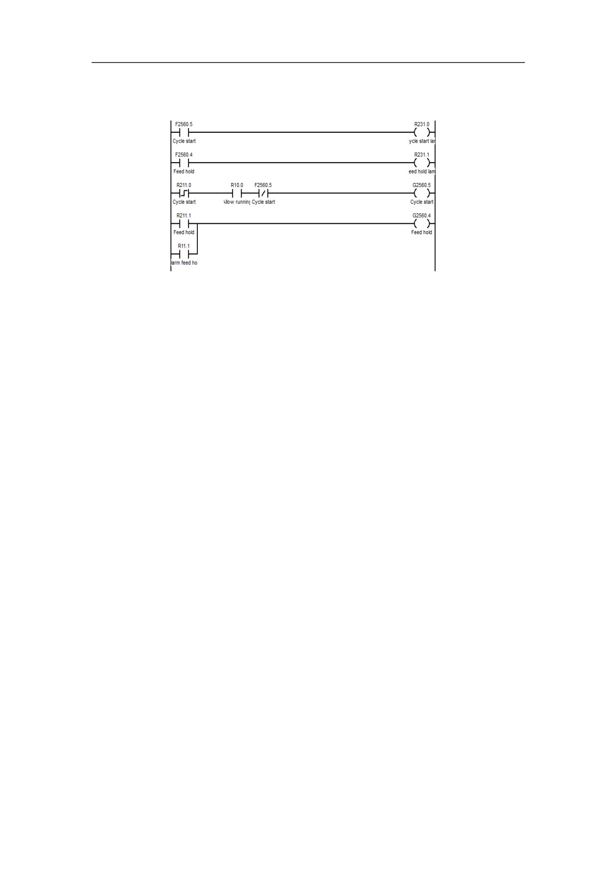
When the working pattern of channel is auto or single block, and is not at cycle
start, set to cycle start. Set to feed hold under the status of cycle start. If the
setting is successful, the system will be at the state of feed hold.
169
HNC-8-PLC Component specification
6. Extended function module
Extension Function Module
This chapter includes:
6.1 NC Function
6.2 Functional Unit of Axis
6.3 System Function
170
HNC-8-PLC Component specification
6. Extended function module
NC Function
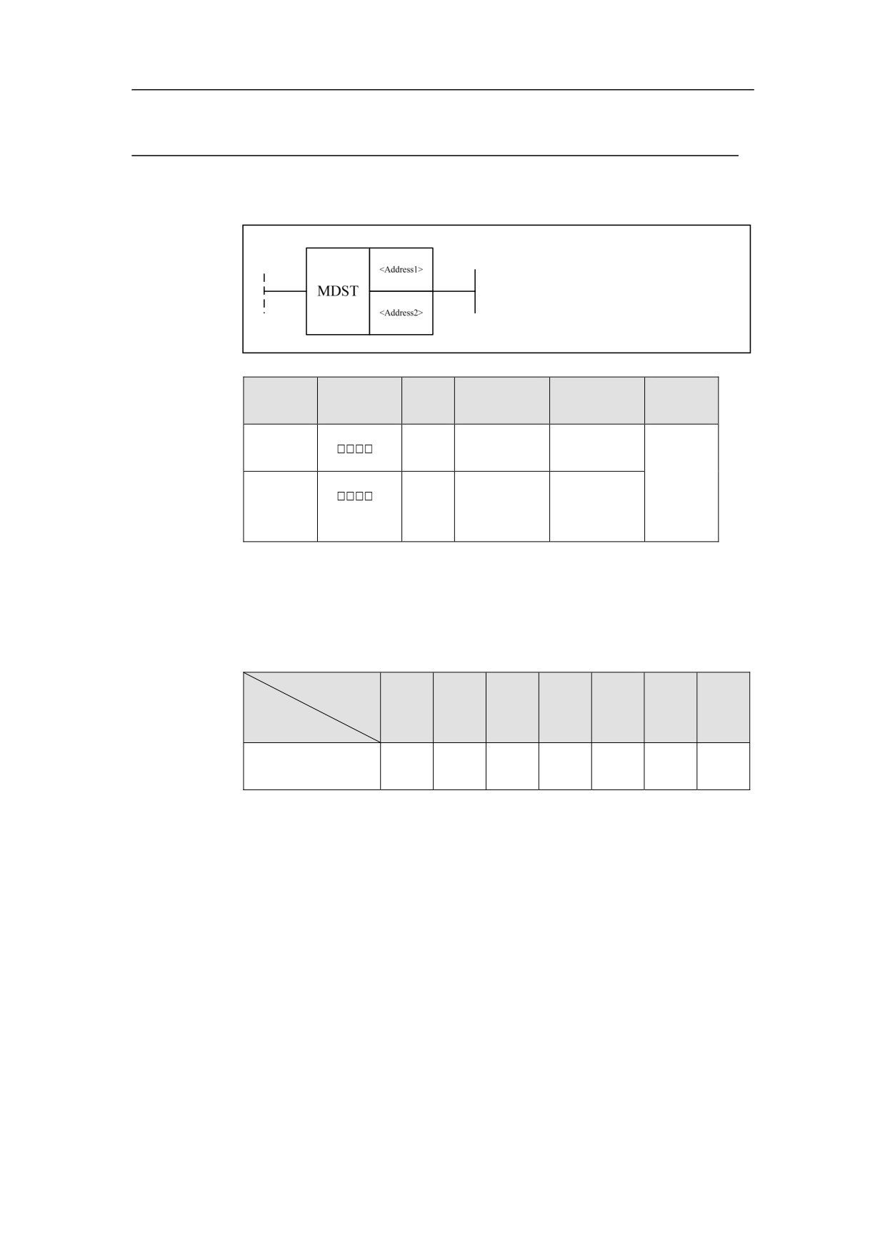
Channel Mode Setting MDST
Format
Paramet
Parameter
Data
Storage
Properti
Explanation
er
form
type
area
es
<Addres
INT
Constant
Channel No.
s 1>
Pre ○
Constant, F,
<Addres
Work mode
Post ×
INT
G, R, W, D,
s 2>
value
P, B
Function
Set the work mode of the current channel (Auto, Single-block, Manual,
Increment, Reference home, Handwheel, PMC)
Parameter
Refere
Work mode
Single-
Manu
Incre
Hand
Auto
nce
PMC
Parameter
block
al
ment
wheel
home
D2□□□
1
2
4
8
16
32
64
Supplemen
If one of channel state is axis homing, switching mode will not be allowed.
tary note
171