HNC-8 Numerical Control System Software. Maual of PLC Programming (V1.24) - page 7
HNC-8-PLC Component specification
6. Extended function module
Example
Ladder
Diagram
Stateme
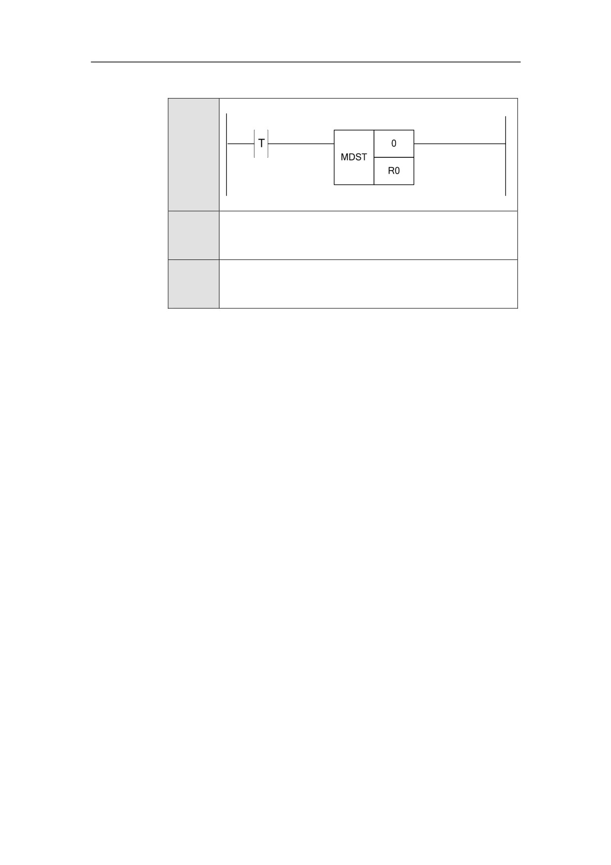
MDST 0 R0
nt List
Descripti
Set the work mode of channel 0 based on the value of R0.
on
172
HNC-8-PLC Component specification
6. Extended function module
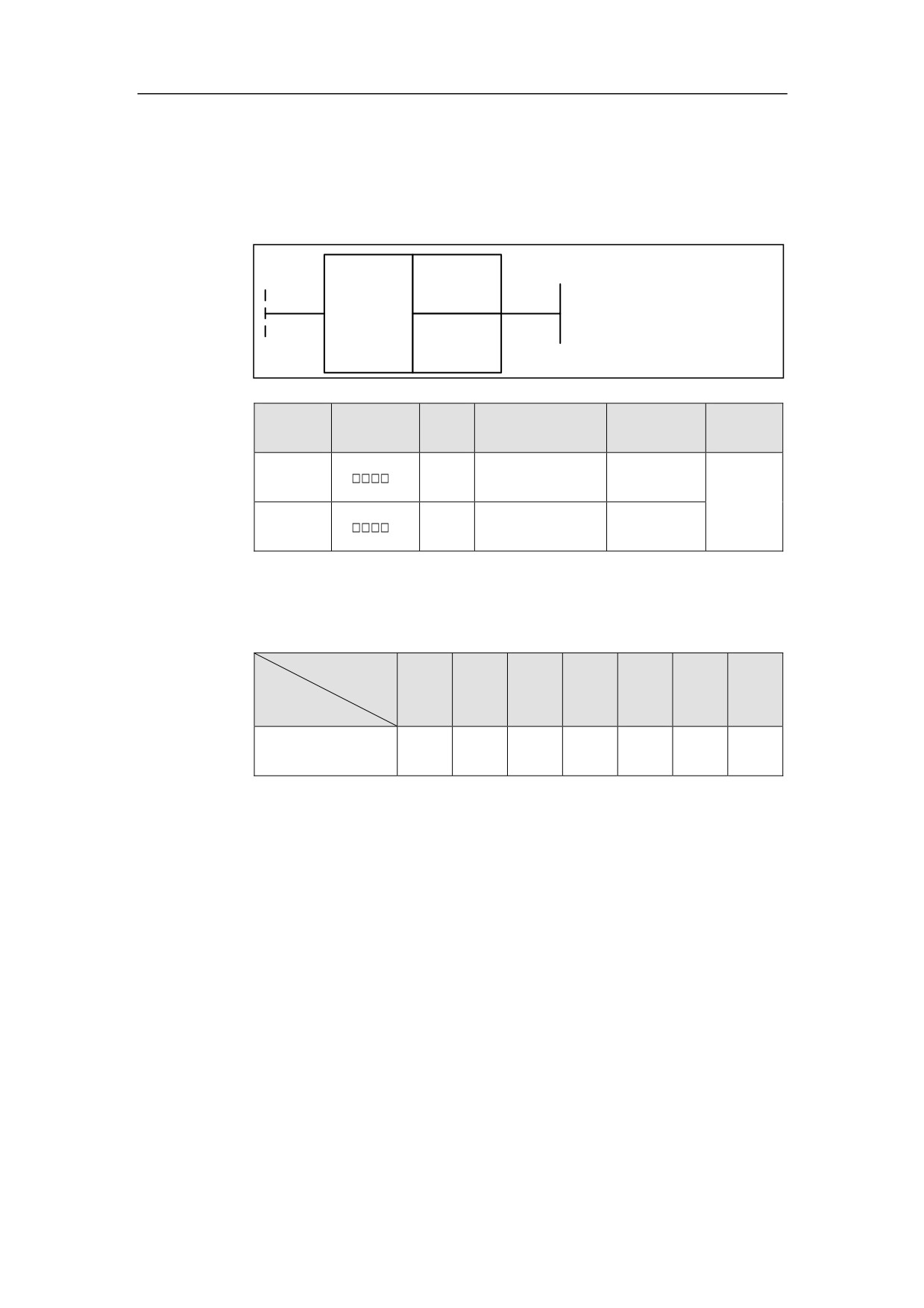
Channel Mode Getting MDGT
Format
<Address 1>
MDGT
<Address 2>
Paramet
Parameter
Data
Properti
Storage area
Explanation
er
form
type
es
<Addres
INT
Constant
Channel No.
Pre ○
s 1>
<Addres
Constant, F, G, R,
Work mode
Post ×
INT
s 2>
W, D, P, B
value
Function
To get the work mode value of the current channel.
Parameter
Refere
Work mode
Single-
Manu
Incre
Hand
Auto
nce
PMC
Parameter
block
al
ment
wheel
home
D2□□□
1
2
4
8
16
32
64
Supplemen
If one of channel state is axis homing, switching mode will not be allowed.
tary note
Example
173
HNC-8-PLC Component specification
6. Extended function module
Ladder
Diagram
Stateme
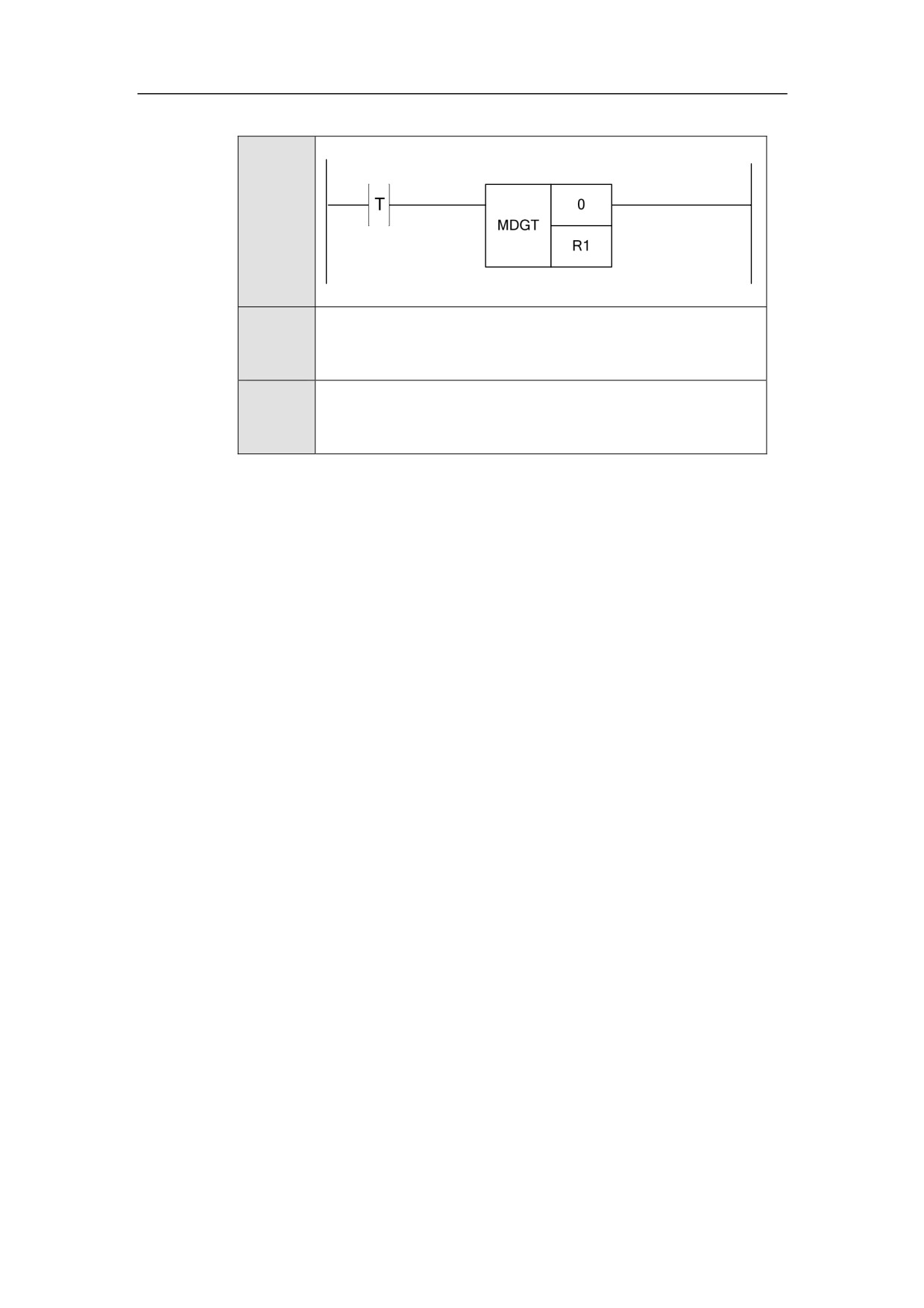
MDGT 0 R1
nt List
Descripti
Take the work mode of Channel 0 into R1 register.
on
174
HNC-8-PLC Component specification
6. Extended function module
Mode MDI
Format
Paramet
Parameter
Data
Properti
Storage area
Explanation
er
form
type
es
Pre ○
<Addres
INT
Constant
Channel No.
s 1>
Post ×
Function
To get MDI mode of the channel.
Parameter
Parameter 1: channel No.
Example
Ladder
Diagram
Stateme
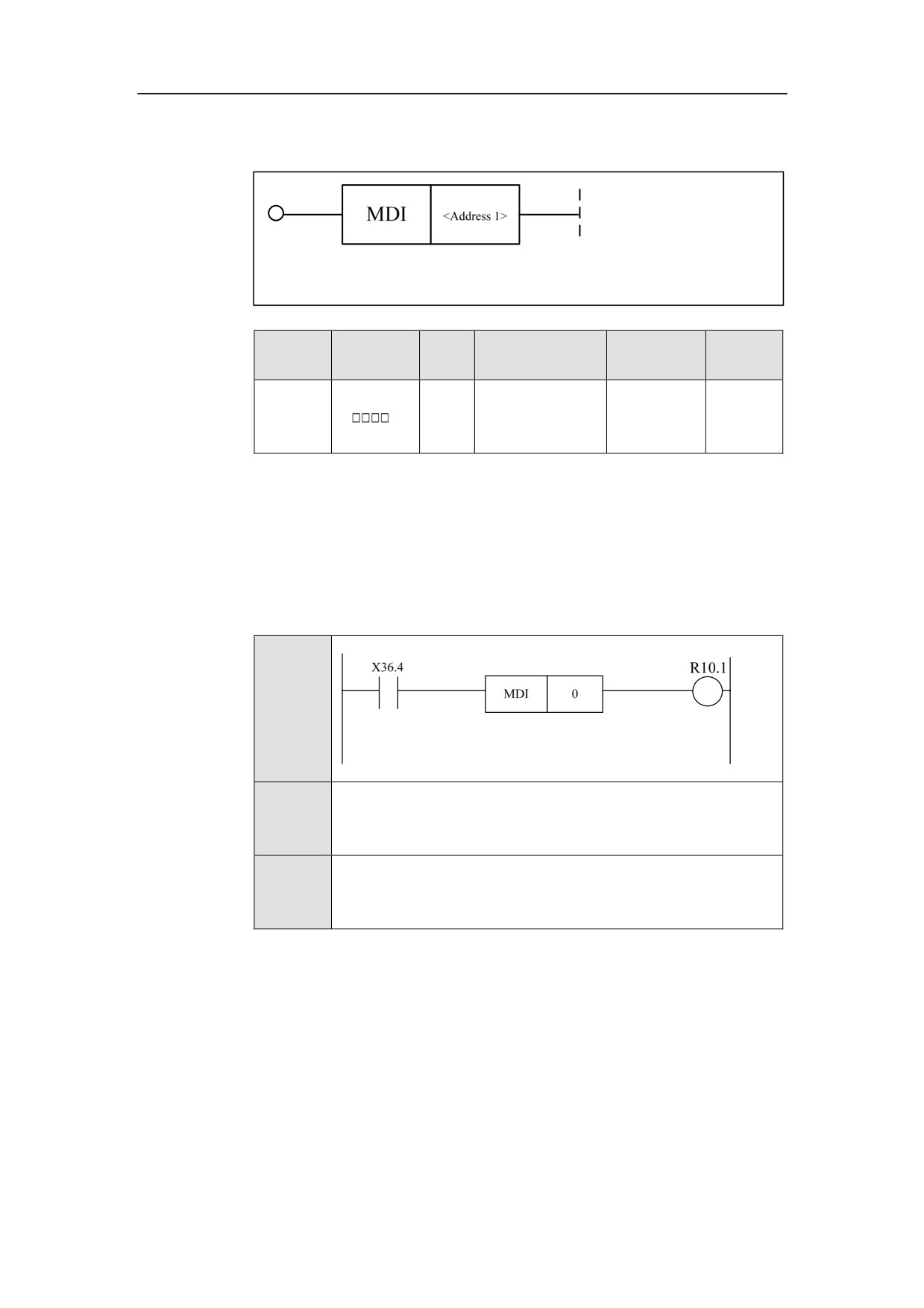
MDI 0
nt List
Descripti
When X36.4 is turned on, channel 0 is in MDI mode.
on
175
HNC-8-PLC Component specification
6. Extended function module
Locking Channel MST
Format
MST
<Address 1>
Paramet
Parameter
Data
Properti
Storage area
Explanation
er
form
type
es
Pre √
<Addres
INT
Constant
Channel No.
s 1>
Post ×
Function
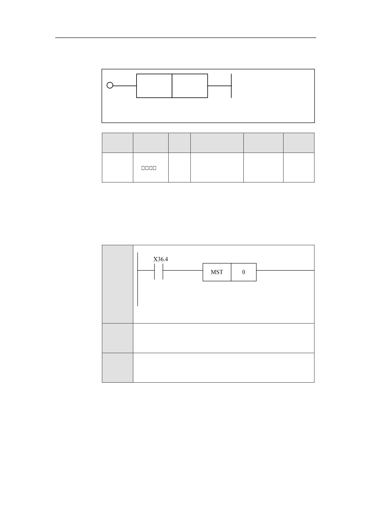
Lock the channel MST. When this function is turned on, all MST instructions of
this channel are not available, and are skipped.
Example
Ladder
Diagram
Stateme
MST 0
nt List
Descripti
When X36.4 is turned on, channel 0 is locked.
on
176
HNC-8-PLC Component specification
6. Extended function module
Cycle Start CYCLE
Format
CYCLE
<Address 1>
Paramet
Parameter
Data
Properti
Storage area
Explanation
er
form
type
es
Pre √
<Addres
INT
Constant
Channel No.
s 1>
Post ×
Function
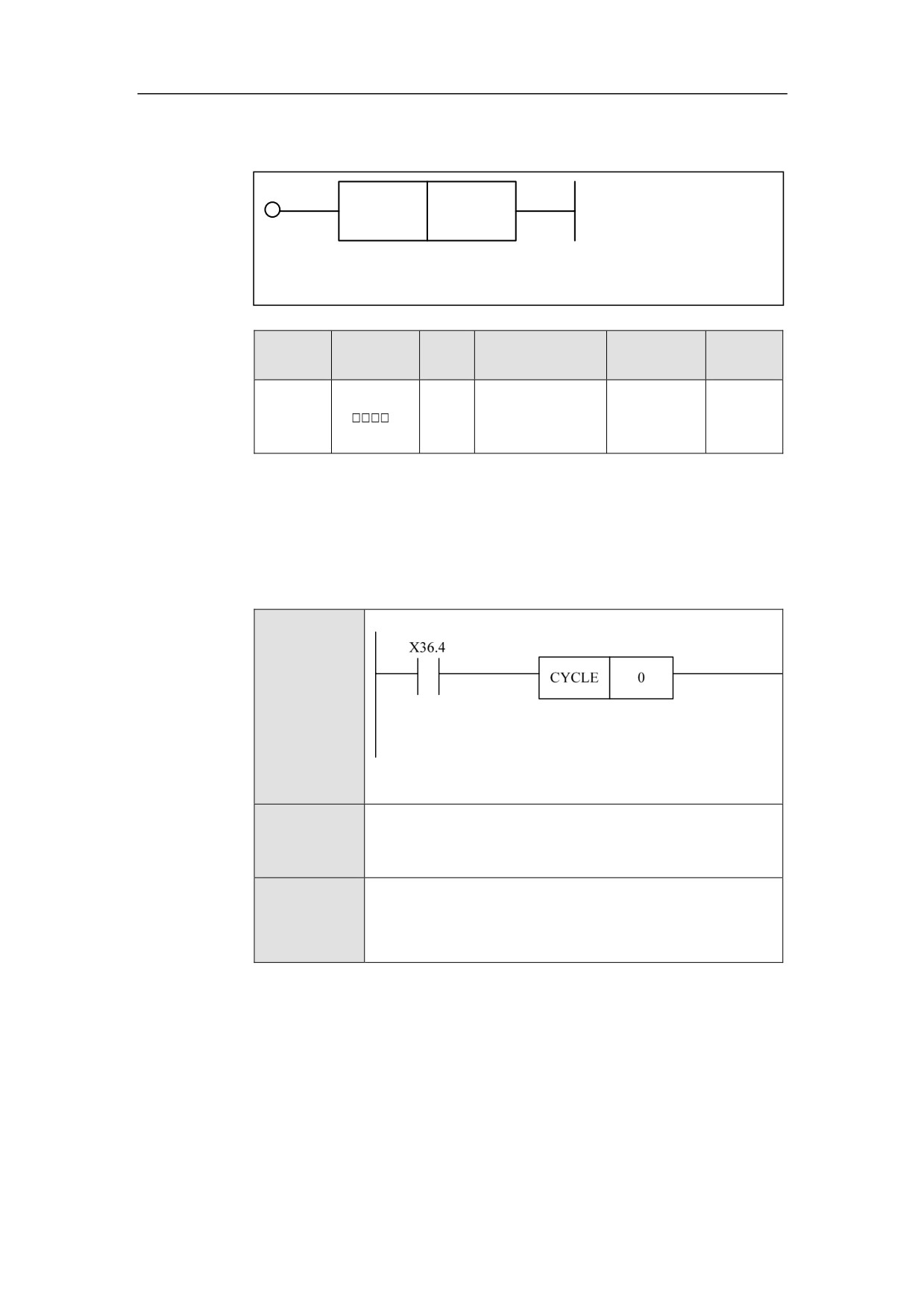
Set the channel which needs cycle start by parameter, and perform cycle start via
ACT signal.
Example
Ladder
Diagram
Statement
CYCLE 0
List
Description
When X36.4 is turned on, set the channel 0 to cycle start.
177
HNC-8-PLC Component specification
6. Extended function module
Emergency Stop STOP
Format
STOP
<Address 1>
Paramet
Parameter
Data
Properti
Storage area
Explanation
er
form
type
es
Pre √
<Addres
INT
Constant
Channel No.
s 1>
Post ×
Function
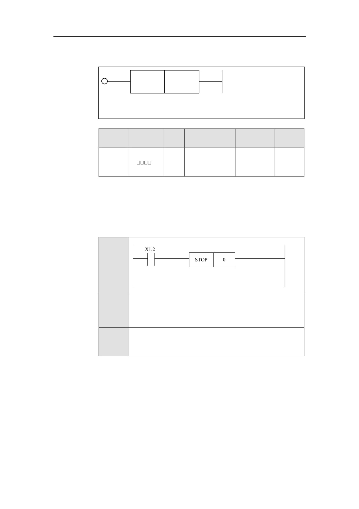
Set the channel which needs emergency stop by parameter, and start
emergency stop via ACT signal.
Example
Ladder
Diagram
LD X1.2
Stateme
nt List
STOP
0
Descripti
When X1.2 is turned on, set the channel 0 to emergency stop.
on
178
HNC-8-PLC Component specification
6. Extended function module
Reset RESET
Format
RESET
<Address 1>
Paramet
Parameter
Data
Properti
Storage area
Explanation
er
form
type
es
Pre √
<Addres
INT
Constant
Channel No.
s 1>
Post ×
Function
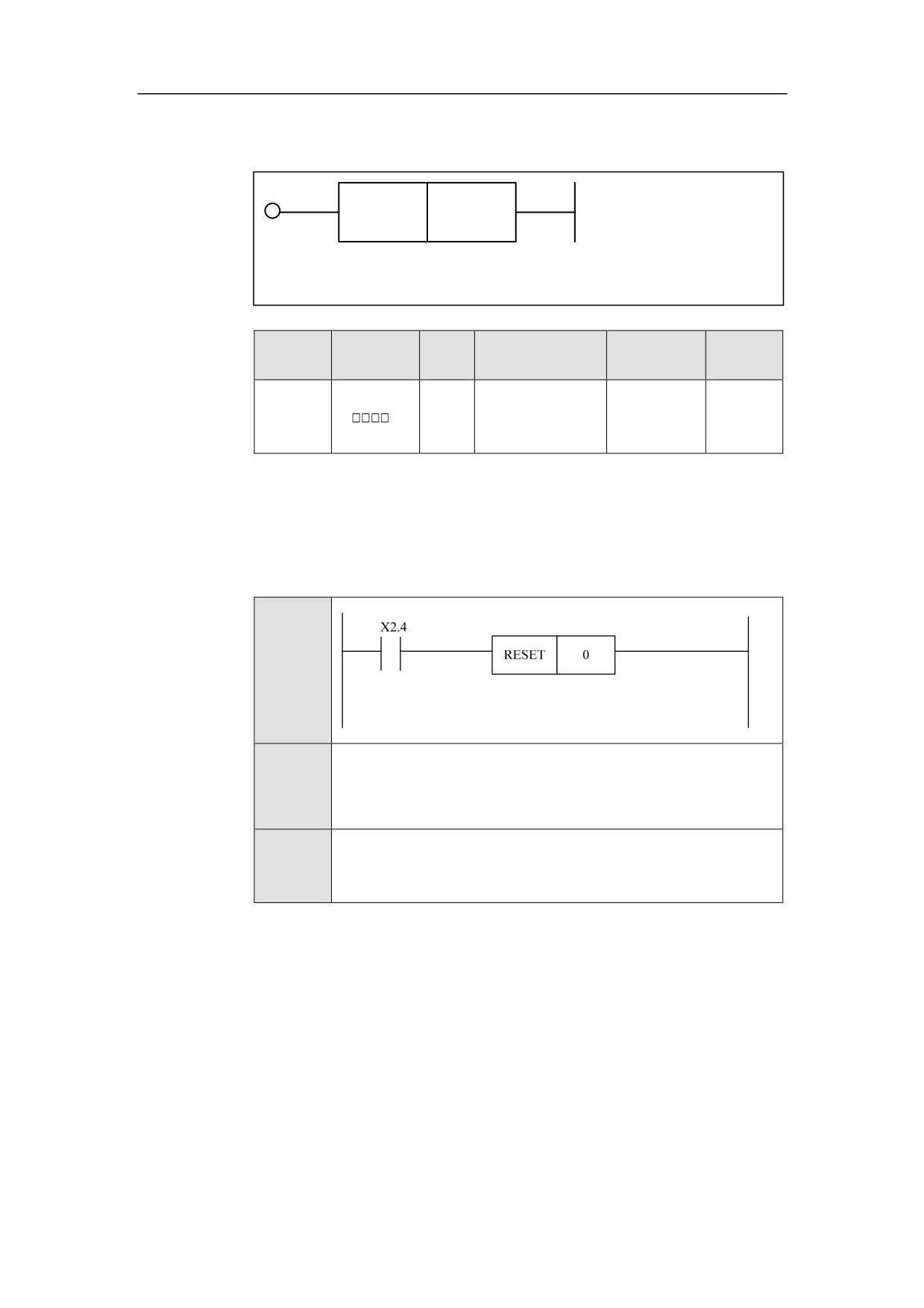
Set the channel which needs reset by parameter, and activate reset via ACT
signal.
Example
Ladder
Diagram
LD X2.4
Stateme
nt List
RESET
0
Descripti
When X2.4 is turned on, the channel 0 is set to reset.
on
179
HNC-8-PLC Component specification
6. Extended function module
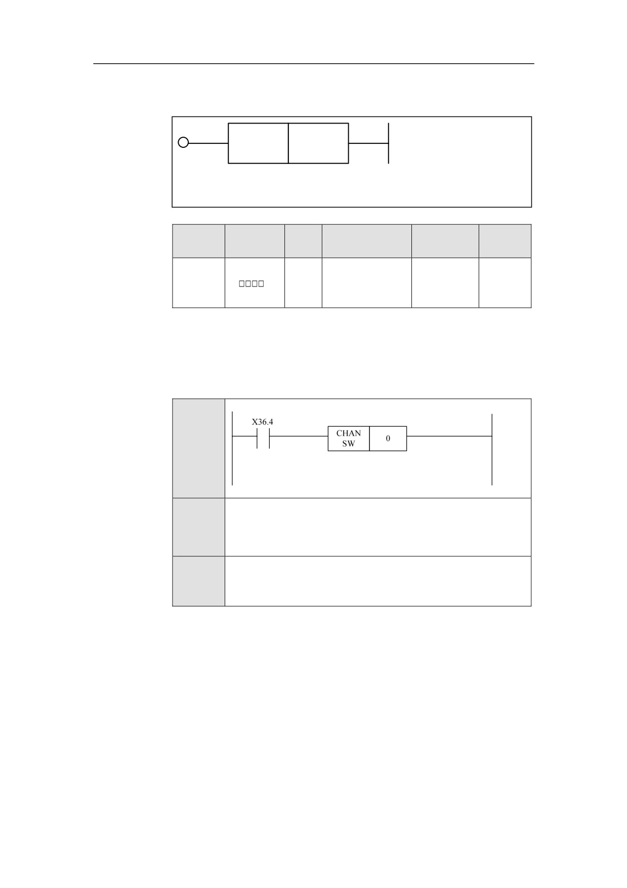
Channel Exchange CHANSW
Format
CHAN
<Address 1>
SW
Paramet
Parameter
Data
Properti
Storage area
Explanation
er
form
type
es
Set
the
Pre √
<Addres
INT
Constant
channel of
s 1>
Post ×
feedhold
Function
Parameter Set the channel which needs to be exchanged by parameter, and
enable the channel exchange via ACT signal.
Example
Ladder
Diagram
LD X36.4
Stateme
nt List
CHANSW
0
Descripti
When X36.4 is turned on, set the channel 0 to the active channel.
on
180
HNC-8-PLC Component specification
6. Extended function module
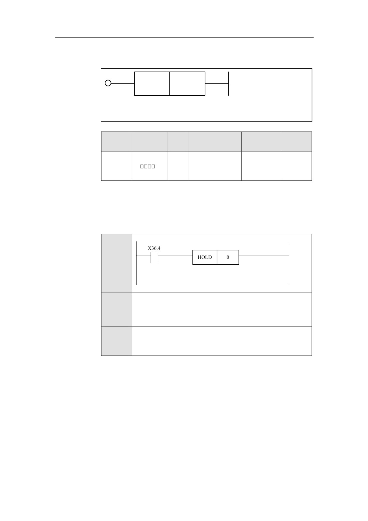
Feed Hold Start HOLD
Format
HOLD
<Address 1>
Paramet
Parameter
Data
Properti
Storage area
Explanation
er
form
type
es
Set
the
Pre √
<Addres
INT
Constant
channel of
s 1>
Post ×
feedhold
Function
Parameter Set the channel which needs feed hold by parameter, and enable
feed hold through ACT signal.
Example
Ladder
Diagram
LD X36.4
Stateme
nt List
HOLD
0
Descripti
When X36.4 is turned on, set the channel 0 to feed hold.
on
181
HNC-8-PLC Component specification
6. Extended function module
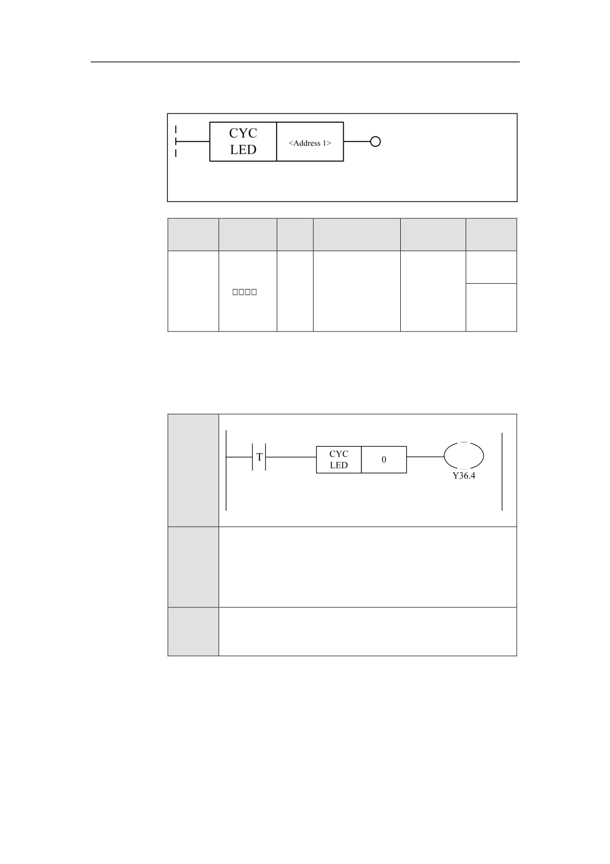
Cycle Start LED CYCLED
Format
Paramet
Parameter
Data
Properti
Storage area
Explanation
er
form
type
es
To get eh
Pre ○
channel
<Addres
INT
Constant
which
s 1>
needs cycle
Post ×
start.
Function
Set the channel that needs cycle start by parameter, if the cycle start is
successfully set, the output will light the cycle start LED.
Example
Ladder
Diagram
LDT
Stateme
CYCLED
0
nt List
OUT Y36.4
Descripti
Get the cycle start state of channel 0, and the cycle start LED is
on
lit.
182
HNC-8-PLC Component specification
6. Extended function module
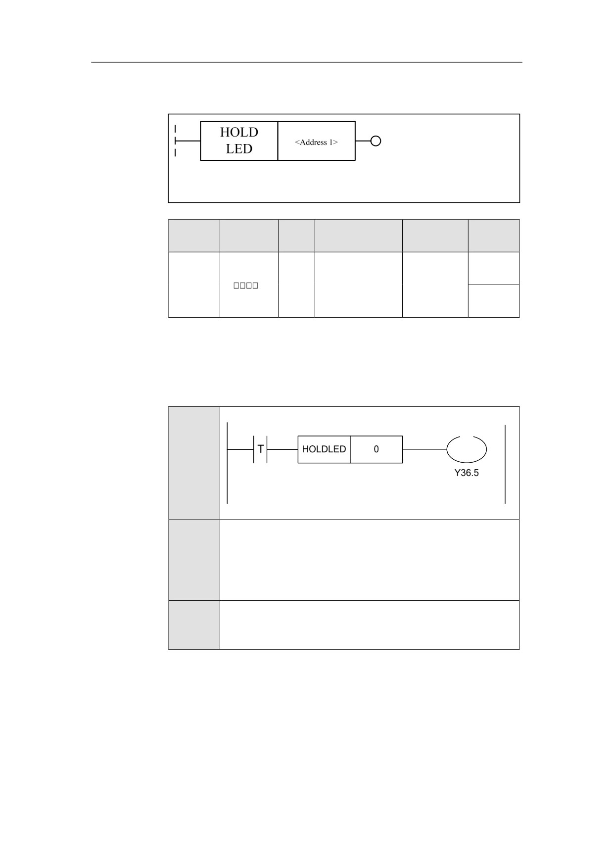
Feed Hold LED HOLDLED
Format
Paramet
Parameter
Data
Properti
Storage area
Explanation
er
form
type
es
To get the
Pre ○
<Addres
channel of
INT
Constant
s 1>
feedhold
Post √
state.
Function
Set the channel where the feed hold LED needs to be lit by parameter, and light
feed hold LED through ACT signal.
Example
Ladder
Diagram
LDT
Stateme
HOLDLED
0
nt List
OUT Y36.5
Descripti
Control the feed hold LED based on the feed hold status of the
on
channel 0.
183
HNC-8-PLC Component specification
6. Extended function module
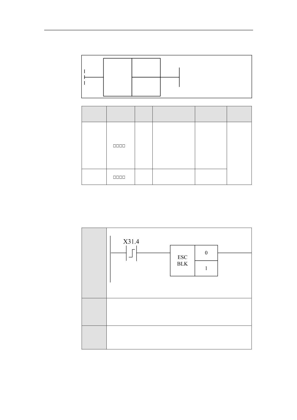
Block Skip(G31)ESCBLK
Format
<Address 1>
ESC
BLK
<Address 2>
Paramet
Parameter
Data
Properti
Storage area
Explanation
er
form
type
es
The channel
where the
<Addres
block skip
INT
Constant
Pre ○
s 1>
function
needs to be
Post ×
activated.
<Addres
The number
INT
Constant
s 2>
of G31
Function
Set the channel where the block skip function needs to be activated by parameter,
and enable this function through ACT signal.
Example
Ladder
Diagram
LDP X31.4
Stateme
nt List
ESCBLK 0 1
Descripti
When the rising edge of X31.4 is turned on, the first G31
on
statement in the channel 0 is activated.
184
HNC-8-PLC Component specification
6. Extended function module
185
HNC-8-PLC Component specification
6. Extended function module
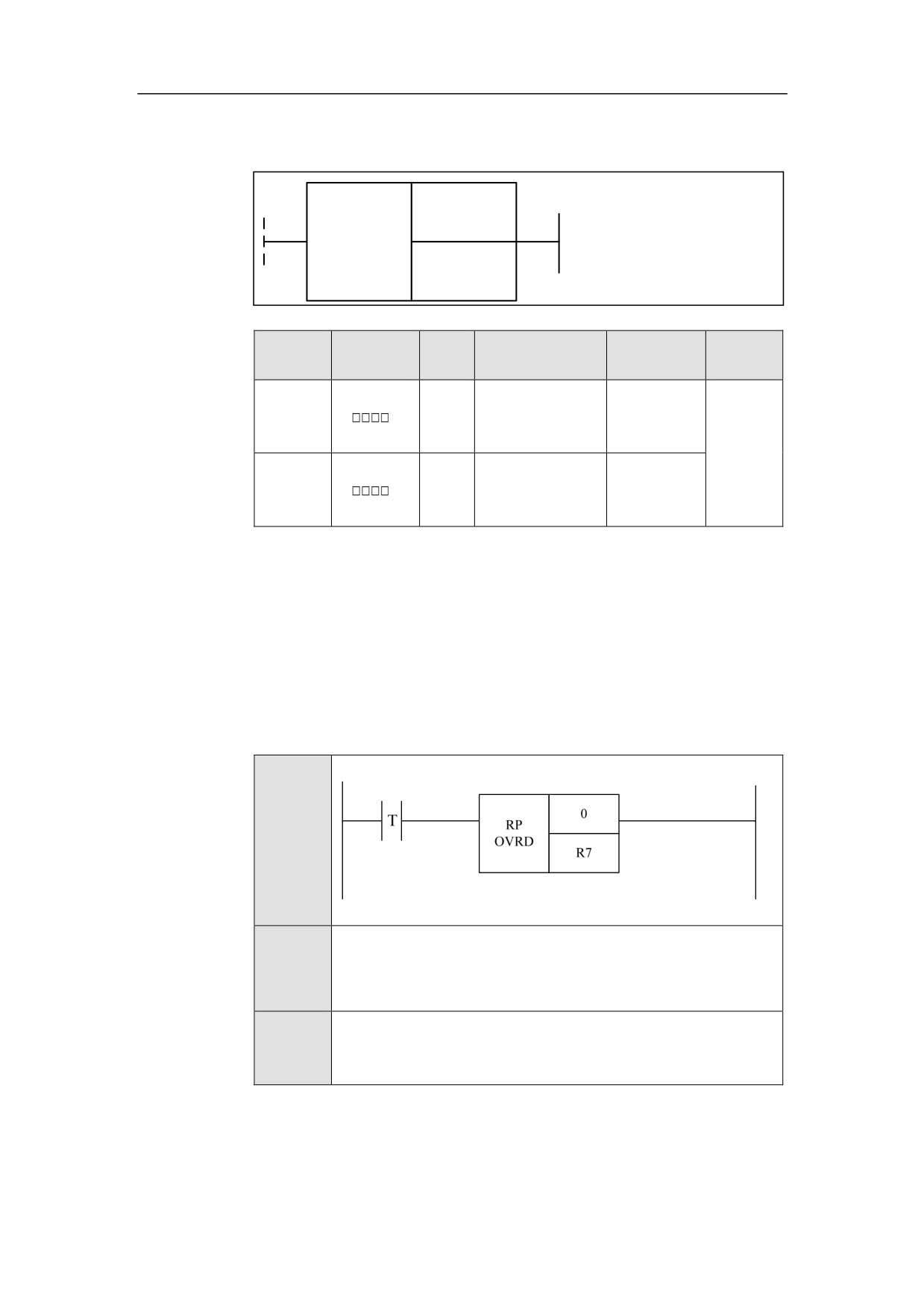
Rapid Override RPOVRD
Format
<Address 1>
RP
OVRD
<Address 2>
Paramet
Parameter
Data
Properti
Storage area
Explanation
er
form
type
es
<Addres
INT
Constant
Channel No.
s 1>
Pre ○
Post ×
<Addres
Constant, X, Y, F,
Override
INT
s 2>
G, R, W, D, P, B
value
Function
The channel is selected by parameter 1. The override value is passed by
parameter 2 with the register. The rapid override function is enabled by ACT.
Supplemen
The override value cannot be changed at the thread-cutting time.
tary note
Example
Ladder
Diagram
LDT
Stateme
nt List
RPOVRD
0 R7
Descripti
Set the rapid override of the channel 0 by the value of R7
on
186
HNC-8-PLC Component specification
6. Extended function module
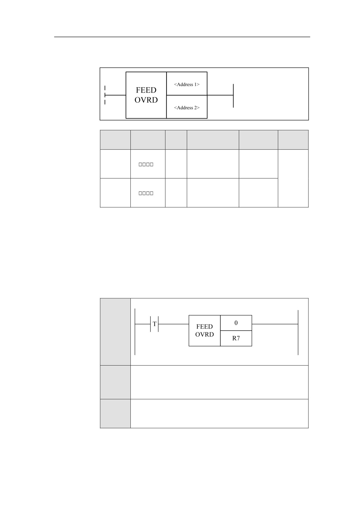
Feedrate Override FEEDOVRD
Format
Paramet
Parameter
Data
Properti
Storage area
Explanation
er
form
type
es
<Addres
INT
Constant
Channel No.
s 1>
Pre ○
Post ×
<Addres
Constant, X, Y, F,
Override
INT
s 2>
G, R, W, D, P, B
value
Function
The channel is selected by parameter 1. The override value is passed by
parameter 2 with the register. The feedrate override function is enabled by ACT.
Supplemen
The override value cannot be changed at the thread-cutting time.
tary note
Example
Ladder
Diagram
LDT
Stateme
nt List
FEEDOVRD
0 R7
Descripti
Set the feedrate override of the channel 0 with the value of R7.
on
187
HNC-8-PLC Component specification
6. Extended function module
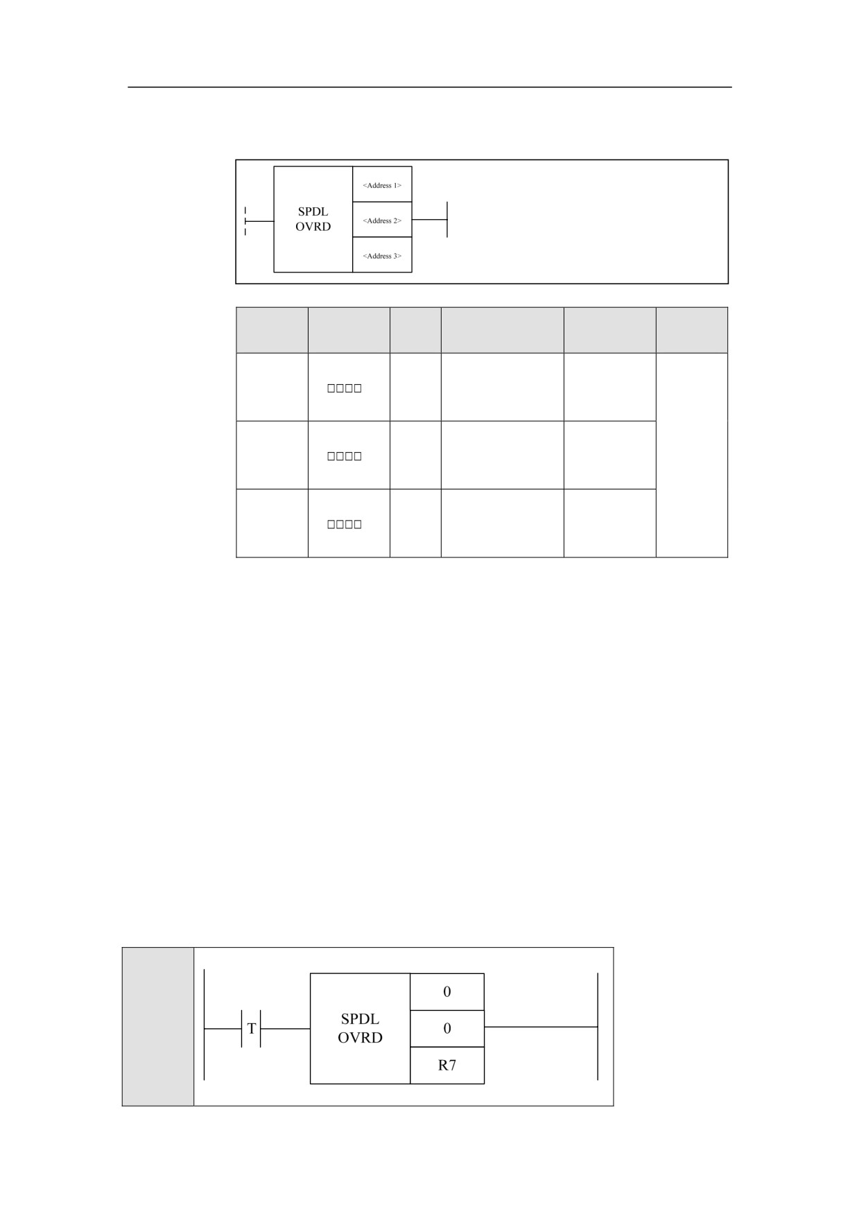
Spindle Override SPDLOVRD
Format
Paramet
Parameter
Data
Properti
Storage area
Explanation
er
form
type
es
<Addres
INT
Constant
Channel No.
s 1>
Pre ○
<Addres
INT
Constant
Spindle No.
s 2>
Post ×
<Addres
Constant, X, Y, F,
Override
INT
s 3>
G, R, W, D, P, B
value
Function
The channel is selected by the parameter 1, the override value is passed by the
parameter 3 with register, and ACT enables rapid override function.
Supplemen
The override value cannot be changed at the thread-cutting time.
tary note
Example
Ladder
Diagram
188

HNC-8-PLC Component specification
6. Extended function module
LDT
Stateme
nt List
SPDLOVRD
0
0 R7
Descripti
Set the No. 0 spindle override value of the channel 0, by the value
on
of R7.
189
HNC-8-PLC Component specification
6. Extended function module
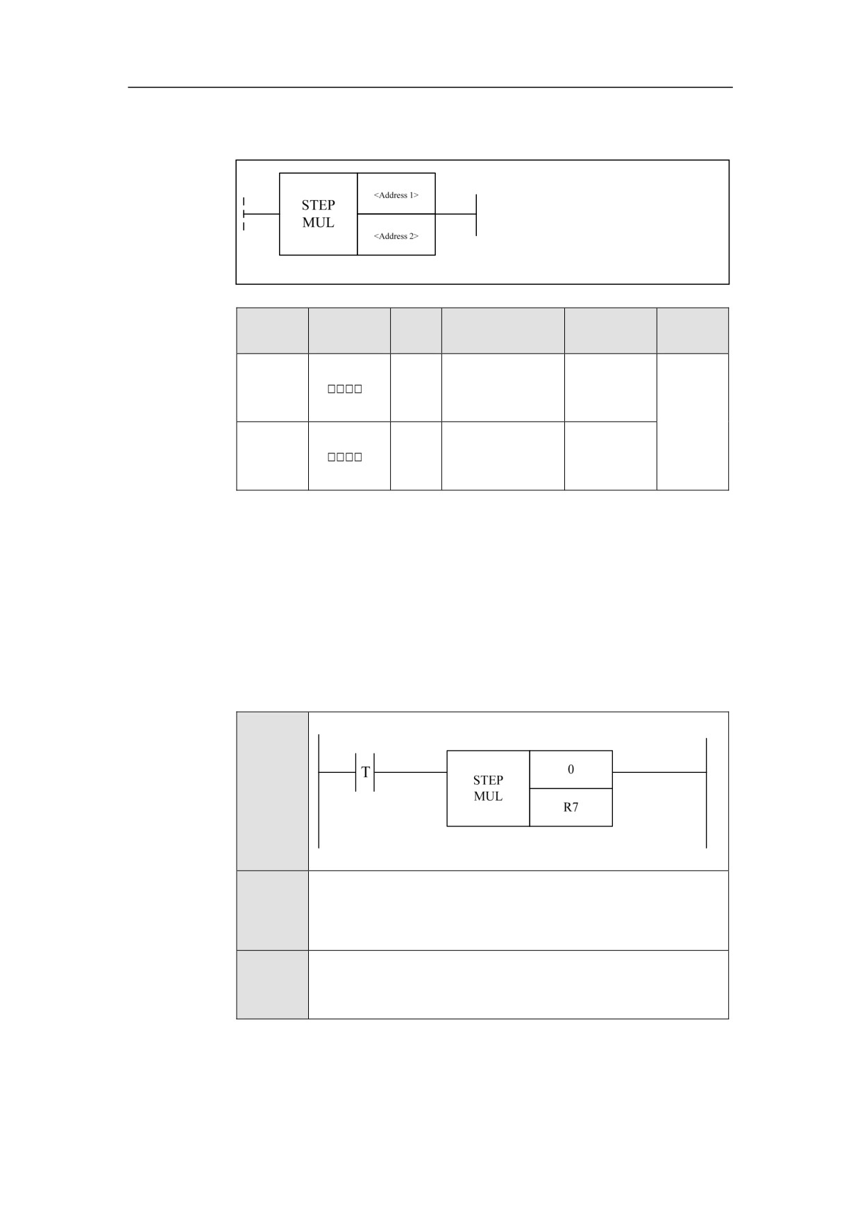
Incremental (Stepping) Rate STEPMUL
Format
Paramet
Parameter
Data
Properti
Storage area
Explanation
er
form
type
es
<Addres
INT
Constant
Axis No.
s 1>
Pre ○
<
Post ×
Constant, X, Y, F,
Address
INT
Rate
G, R, W, D, P, B
2>
Function
Parameter The axis number is set by the parameter 1, the rate is passed by the
parameter 2 with register, and ACT enables feedrate override function.
Supplemen
This function can only be used in the incremental (stepping) status.
tary note
Example
Ladder
Diagram
LDT
Stateme
nt List
STEPMUL
0 R7
Descripti
Set the incremental rate of the channel 0 by the R7 value.
on
190
HNC-8-PLC Component specification
6. Extended function module
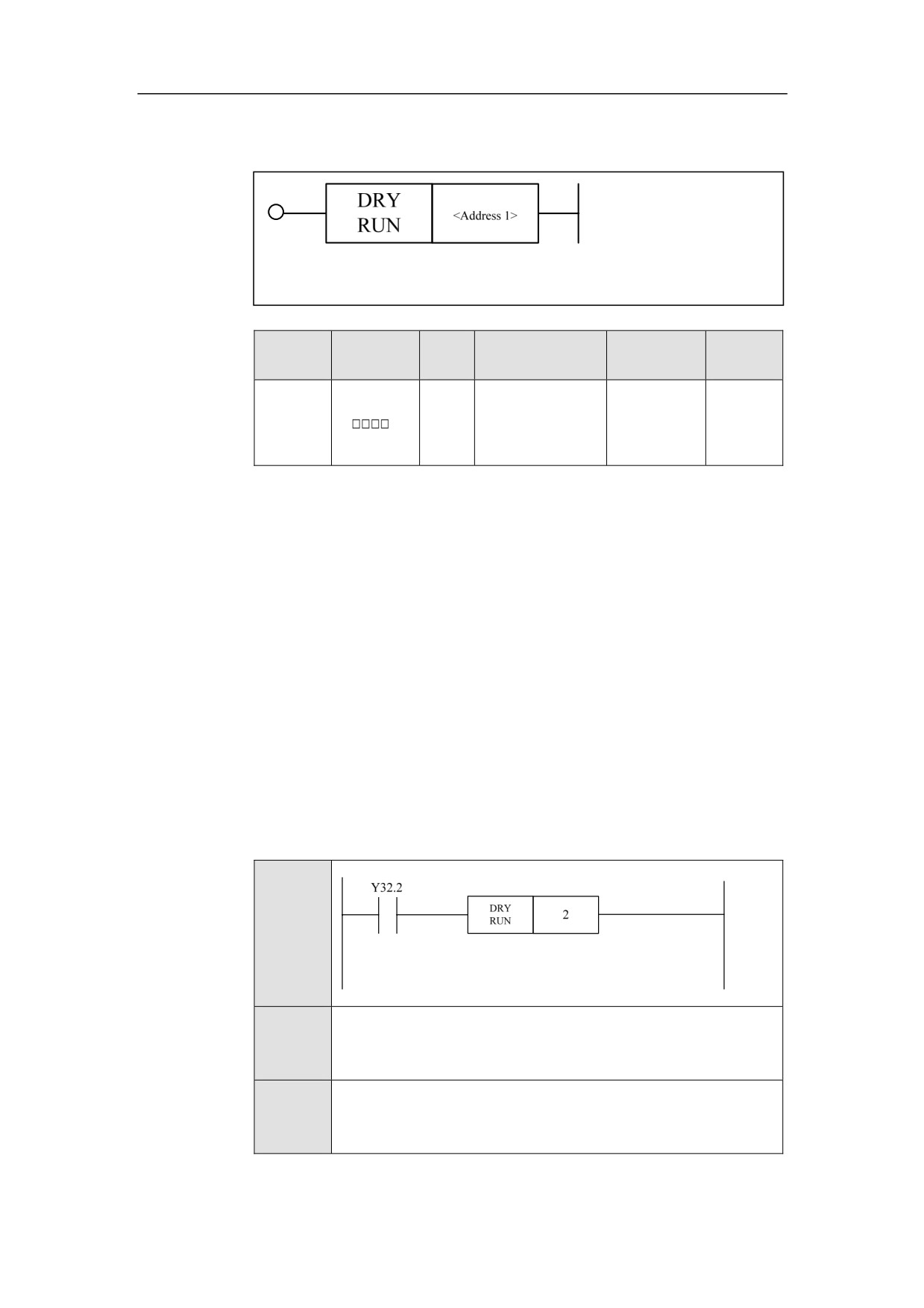
Dryrun DRYRUN
Format
Paramet
Parameter
Data
Properti
Storage area
Explanation
er
form
type
es
Pre √
<Addres
INT
Constant
s 1>
Post ×
Function
Press Dryrun button in the auto mode on the control panel, its indicator lamp is
lit, and CNC is in dryrun status, where the feed rate specified by the program is
ignored, and the coordinate axis moves at the rapidest speed.
The machine doesn’t perform actual cutting in dryrun status. The purpose of
dryrun is to confirm the cutting path and the program.
During the process of actual cutting, this function must be turned off; otherwise,
it may cause danger.
This function cannot work on thread cutting.
Parameter
Parameter 1: channel No.
Example
Ladder
Diagram
Stateme
DRYRUN 2
nt List
Descripti
When Y32.2 is turned on, the channel 2 is in dry run.
on
191
HNC-8-PLC Component specification
6. Extended function module
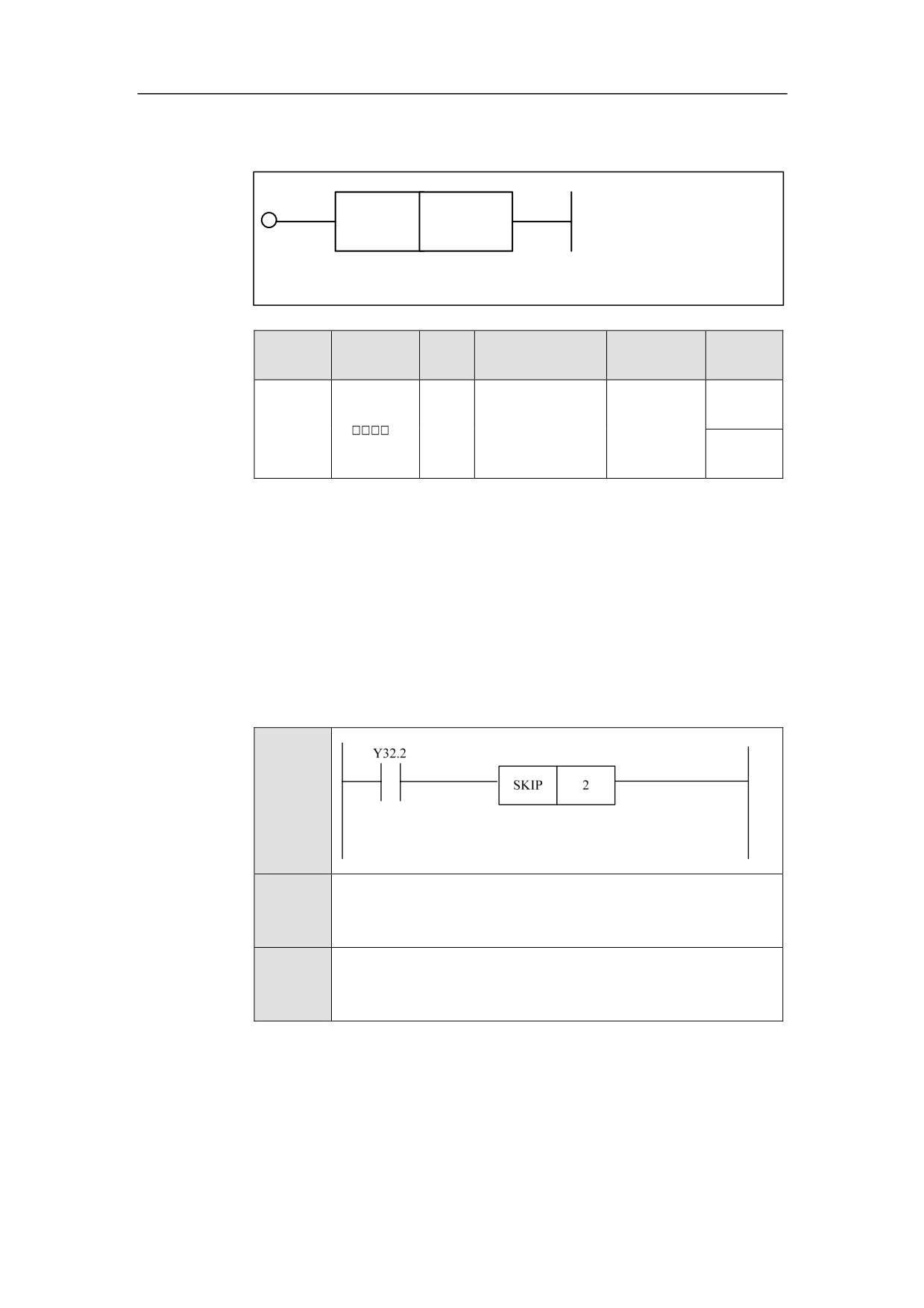
Block Skip SKIP
Format
SKIP
<Address 1>
Paramet
Parameter
Data
Properti
Storage area
Explanation
er
form
type
es
Pre √
<Addres
INT
Constant
s 1>
Post ×
Function
The system can skip some specified blocks in the auto mode. If “/” is put at the
start of a program block, press Block skip, then this block will be skipped in the
auto mode; if Block skip is released, “/” will not work, and this block will be
implemented.
Parameter
Parameter 1: channel No.
Example
Ladder
Diagram
Stateme
SKIP 2
nt List
Descripti
When Y32.2 is turned on, block-skip of channel 2 is valid.
on
192
HNC-8-PLC Component specification
6. Extended function module
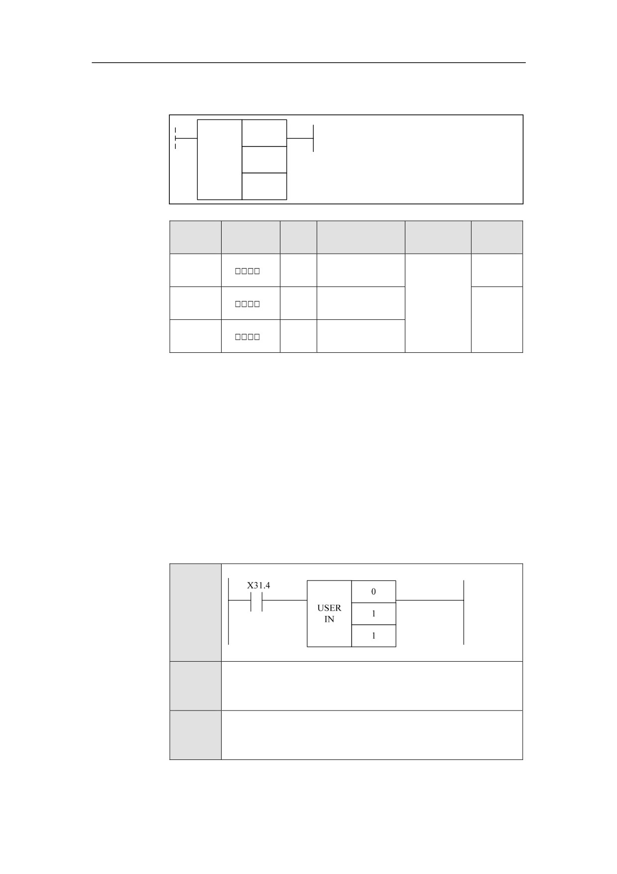
User Input USERIN
Format
<Address 1>
USER
<Address 2>
IN
<Address 3>
Paramet
Parameter
Data
Properti
Storage area
Explanation
er
form
type
es
<Addres
INT
Constant
Pre √
s 1>
<Addres
INT
Constant
s 2>
Post ×
<Addres
INT
Constant
s 3>
Function
Set the user input. When ACT is effective, set user-defined group and bit to 1,
the macro-variable changes accordingly.
Parameter
Parameter 1: channel No.
Parameter 2: not available at present
Parameter 3: power of 2. For example, 17 means that the value of #1190 is
2^17=131072.
Example
Ladder
Diagram
Stateme
USERIN 0 1 1
nt List
Descripti
When X31.4 is turned on, the macro-variable #1190 of user input
on
group which corresponds to the channel 0 is 2.
193
HNC-8-PLC Component specification
6. Extended function module
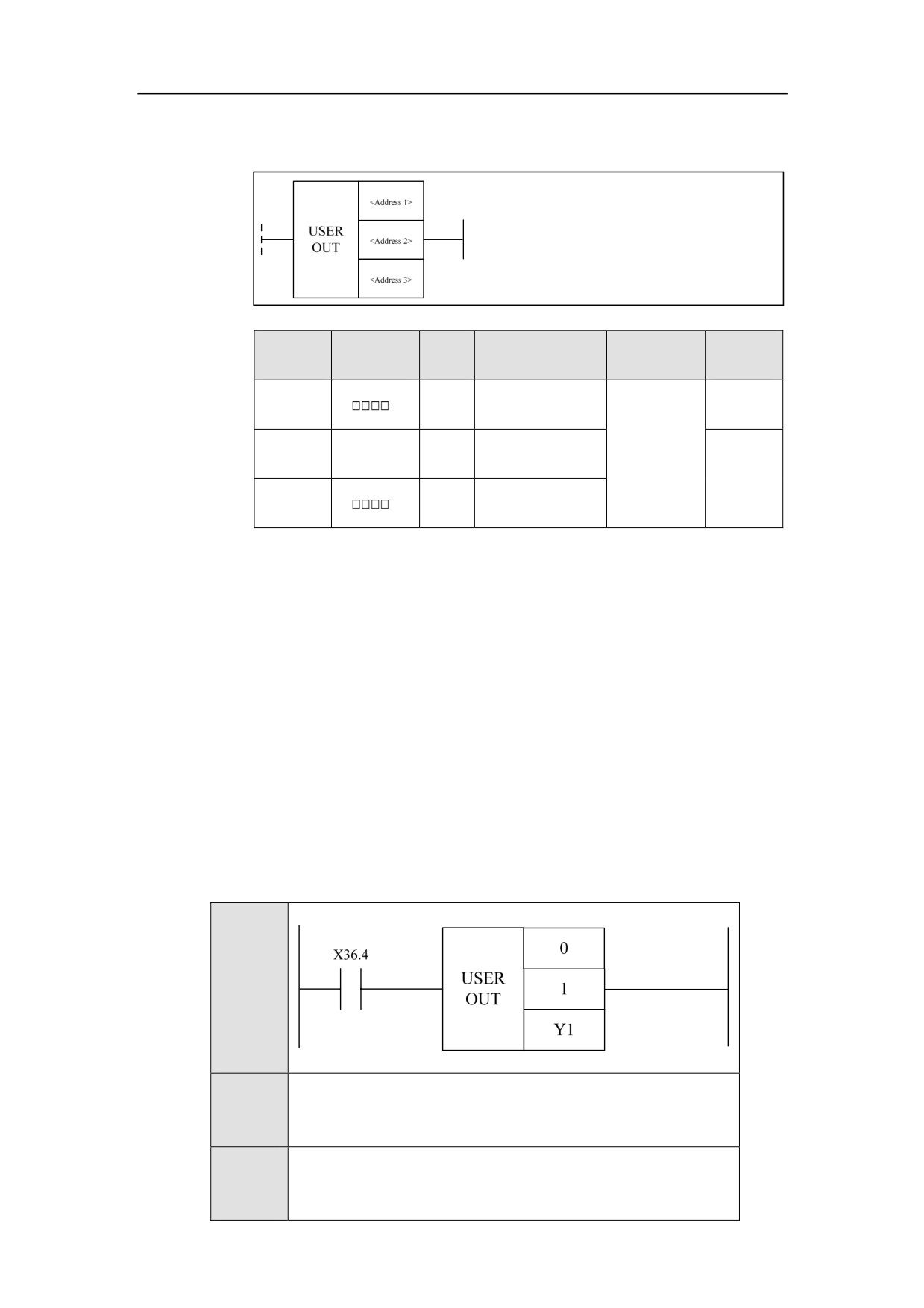
User Output USEROUT
Format
Paramet
Parameter
Data
Properti
Storage area
Explanation
er
form
type
es
<Addres
INT
Constant
Pre ○
s 1>
<Addres
None
None
None
s 2>
Pre ×
<Addres
INT
Y, R
s 3>
Function
Set the user output. Set the value of macro-variable #1191in the program, which
will determine the group number and position number of user-defined output.
32-bit output is defined, and four groups of 8-bit outputs are obtained. The start
address of output is defined by parameter 3.
Parameter
Parameter 1: channel No.
Parameter 2: not available at present.
Parameter 3: Parameter 3: the start address of output register. The output value
is 32-bit. Therefore, for y register of 8-bit, four y registers are used.
Exampl
e
Ladder
Diagram
Stateme
USEROUT 0 1 Y1
nt List
Descripti
Y1.2 and Y1.3 will be output, and other bits of Y1 to Y4 are 0.
on
194
HNC-8-PLC Component specification
6. Extended function module
195
HNC-8-PLC Component specification
6. Extended function module
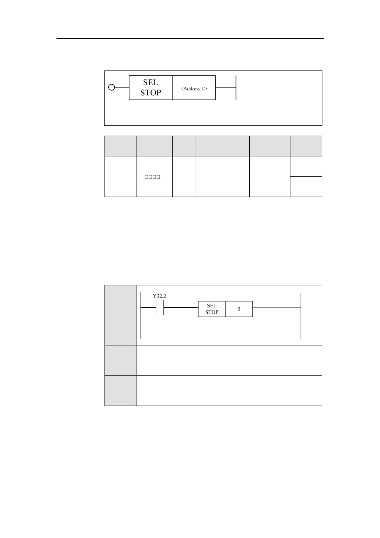
Selection Stop SELSTOP
Format
Paramet
Parameter
Data
Properti
Storage area
Explanation
er
form
type
es
Pre √
<Addres
INT
Constant
s 1>
Post ×
Function
When “Selection stop” is enabled (the indicator light is on), the program stops at
M01 in the auto mode.
Parameter
Parameter 1: channel No.
Example
Ladder
Diagram
Stateme
SELSTOP 0
nt List
Descripti
When Y32.2 is turned on, the selection stop of channel 0 is
on
effective.
196
HNC-8-PLC Component specification
6. Extended function module
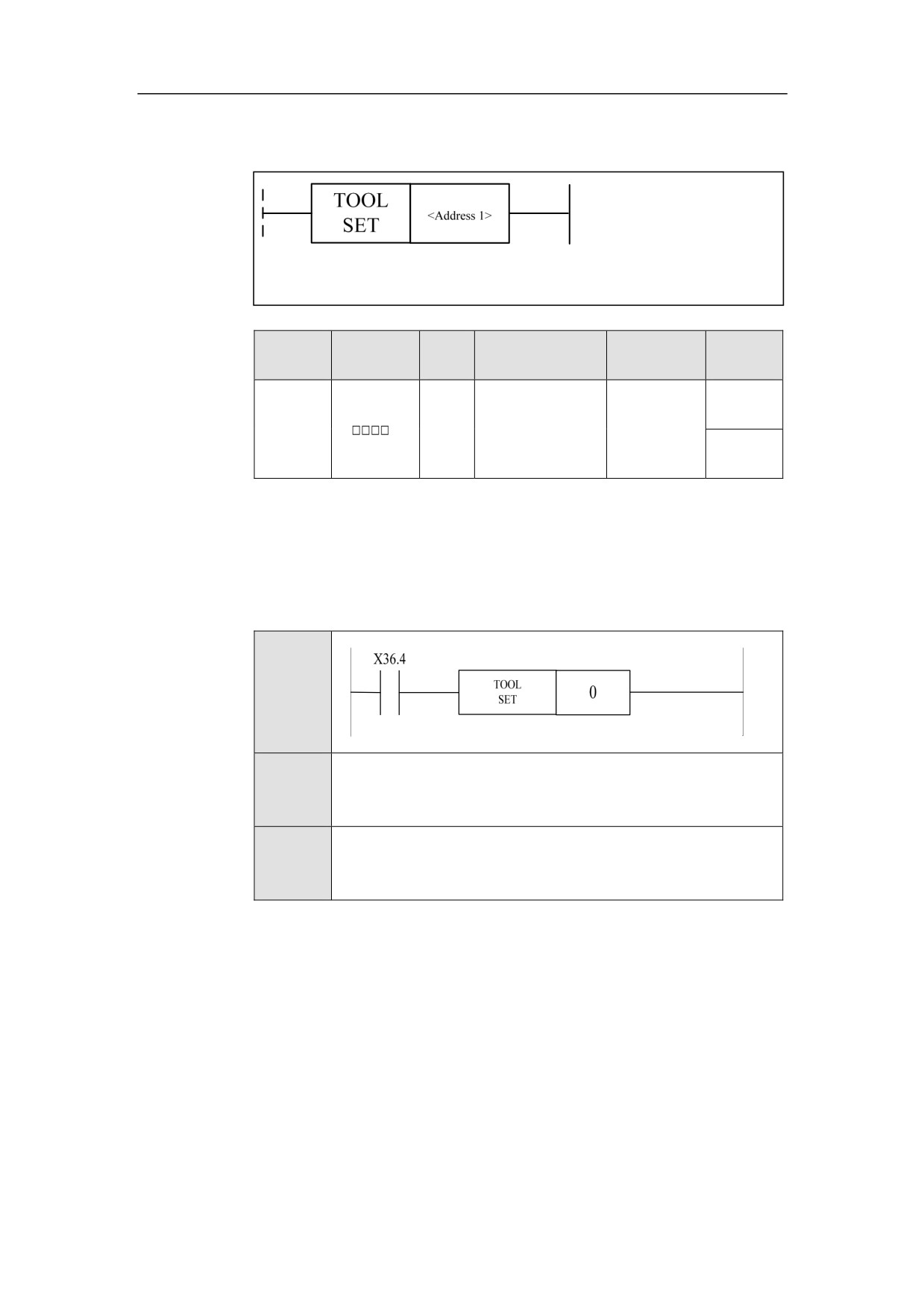
Vector Tool Direction Setting TOOLSET
Format
Paramet
Parameter
Data
Properti
Storage area
Explanation
er
form
type
es
Pre ×
<Addres
INT
Constant
Channel No.
s 1>
Post √
Function
This function is generally used for 5-axis machining. Set the vector direction of
the current tool in this channel to Z direction, enable this function, manually feed
and retract the tool along the vector direction.
Example
Ladder
Diagram
Stateme
TOOLSET 0
nt List
Descripti
When Y32.2 is turned on, the tool orientation of channel 0 is
on
effective.
197
HNC-8-PLC Component specification
6. Extended function module
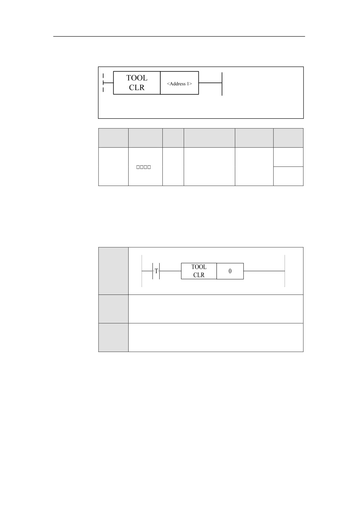
Vector Tool Direction Clear TOOLCLR
Format
Paramet
Parameter
Data
Properti
Storage area
Explanation
er
form
type
es
Pre ×
<Addres
INT
Constant
Channel No.
s 1>
Post √
Function
This function is generally used for 5-axis machining. Z direction is cancelled in
this channel as the vector direction of the current tool. This function is used in
conjunction with TOOLSET function.
Example
Ladder
Diagram
Stateme
TOOLCLR 0
nt List
Descripti
The tool direction of channel 0 is set to be invalid.
on
198
HNC-8-PLC Component specification
6. Extended function module
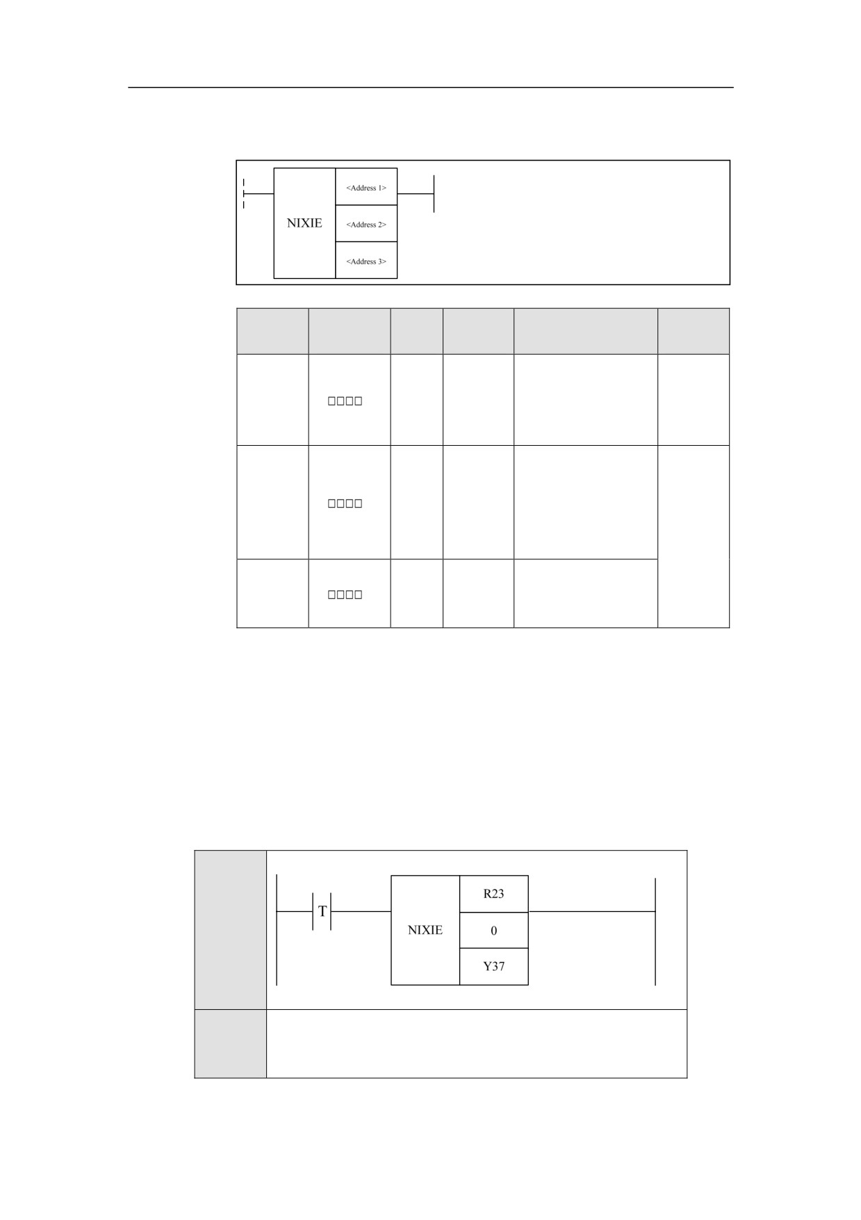
8-bit Nixie Tube NIXIE
Format
Paramet
Parameter
Data
Storage
Properti
Explanation
er
form
type
area
es
Constan
The number to be
<Addres
t, X, Y, F,
INT
shown by the digital
Pre √
s 1>
G, R, W,
tube
D, P, B
”0” indicates single
<Addres
Constan
byte,
and
“1”
INT
s 2>
t
indicates
double-byte.
Post √
<Addres
Y, R, W,
Set the 8-bit digital
BOOL
s 3>
D, B
tube on the panel
Function
The 8-bit digital tube on the panel displays the number of the current tool.
Example
Ladder
Diagram
Stateme
NIXIE R23 0 Y37
nt List
199
HNC-8-PLC Component specification
6. Extended function module
Descripti
The tool number in R23 is displayed to the digital tube.
on
200
HNC-8-PLC Component specification
6. Extended function module
Tool Display TOOLUSE
Format
<Address 1>
TOOL
USE
<Address 2>
Paramet
Parameter
Data
Properti
Storage area
Explanation
er
form
type
es
<Addres
Constant, X, Y, F,
INT
Pre ○
s 1>
G, R, W, D, P, B
<Addres
Constant, X, Y, F,
INT
Post ×
s 2>
G, R, W, D, P, B
Function
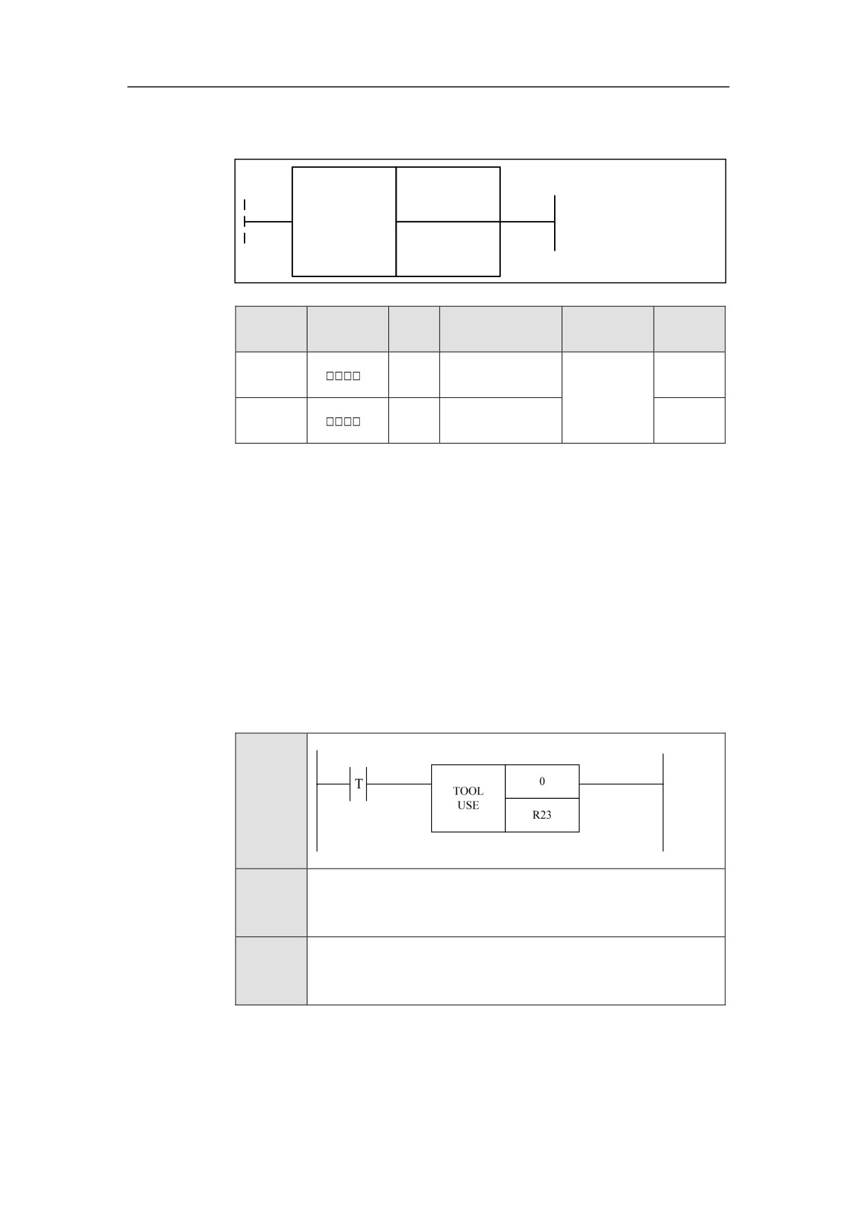
Display the tool number in the currently executed T code to the interface of
CNC.
Parameter
Parameter 1: channel number
Parameter: tool number
Example
Ladder
Diagram
Stateme
TOOLUSE 0 R23
nt List
Descripti
The tool number of channel 0 is displayed on the interface.
on
201
HNC-8-PLC Component specification
6. Extended function module
Functional Unit of Axis
Spindle JOG SPDLJOG
Format
<Address 1>
SPDL
JOG
<Address 2>
Paramete
Parameter
Data
Properti
Storage area
Explanation
r
form
type
es
<Address
INT
Constant
Pre ○
1>
<Address
X, Y, F, G, R, W,
BOOL
Post ×
2>
D, P, B
Function
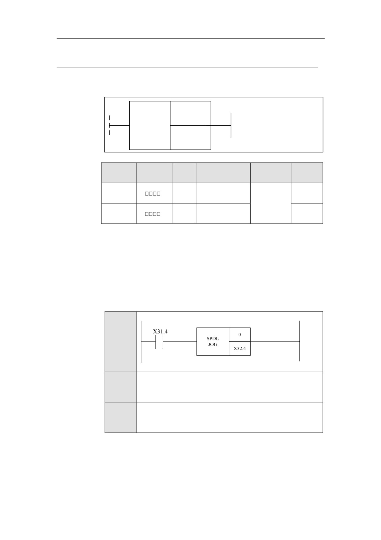
Control spindle manually.
Parameter
Parameter 1: spindle number
Parameter 2:signal of rotation direction;
Example
Ladder
Diagram
Stateme
SPDLJOG 0 X32.4
nt List
Descripti
When X31.4 is effective, if X32.4 is valid, the 0 axis will rotate at
on
the default speed in the clockwise direction.
202