HNC-8 Numerical Control System Software. Maual of PLC Programming (V1.24) - page 5
4. Basic function module
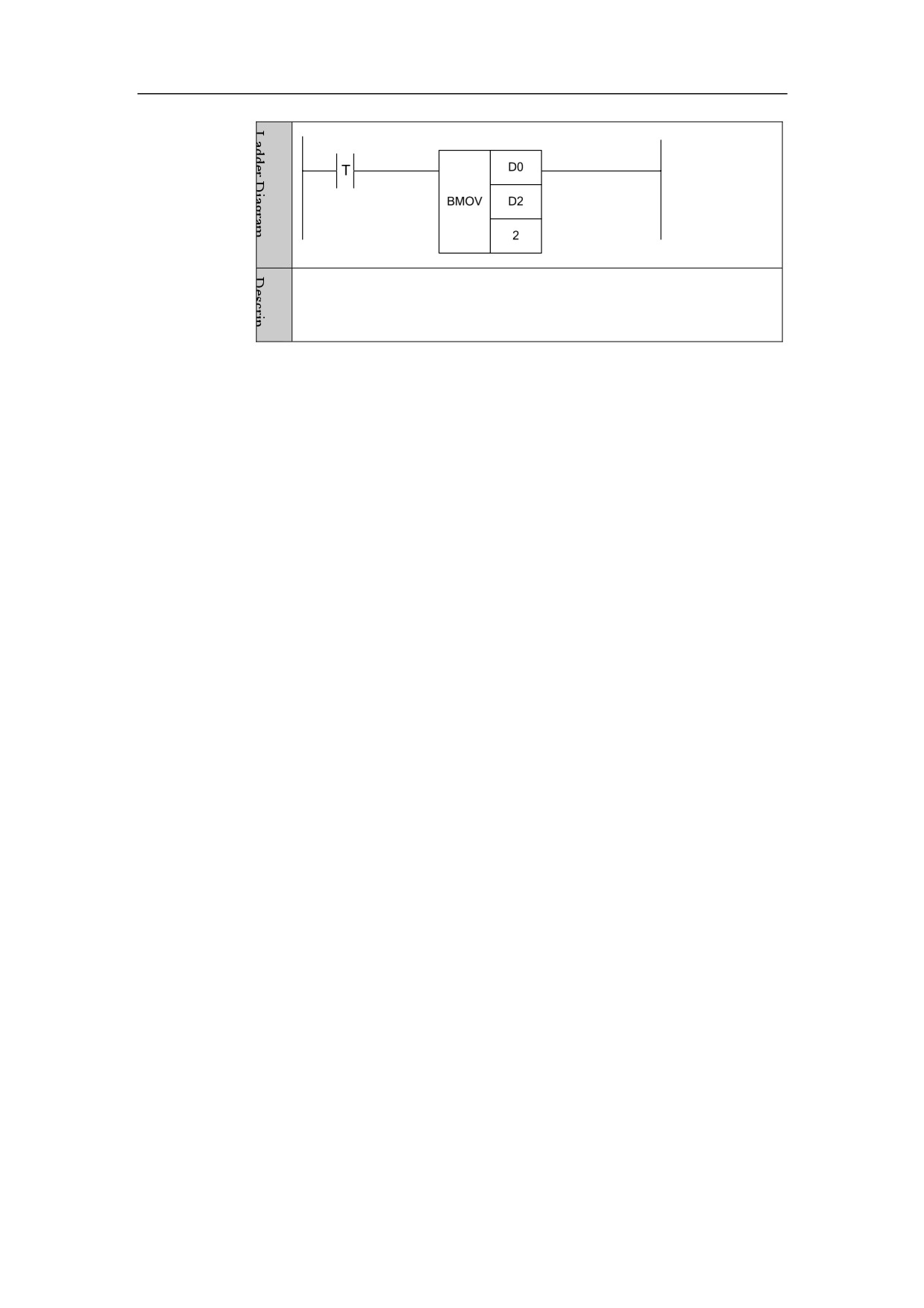
Two data starting from D0 is assigned to two positions starting from D2,
that is, D0 is assigned to D2, and D1 is assigned to D3.
110
4. Basic function module
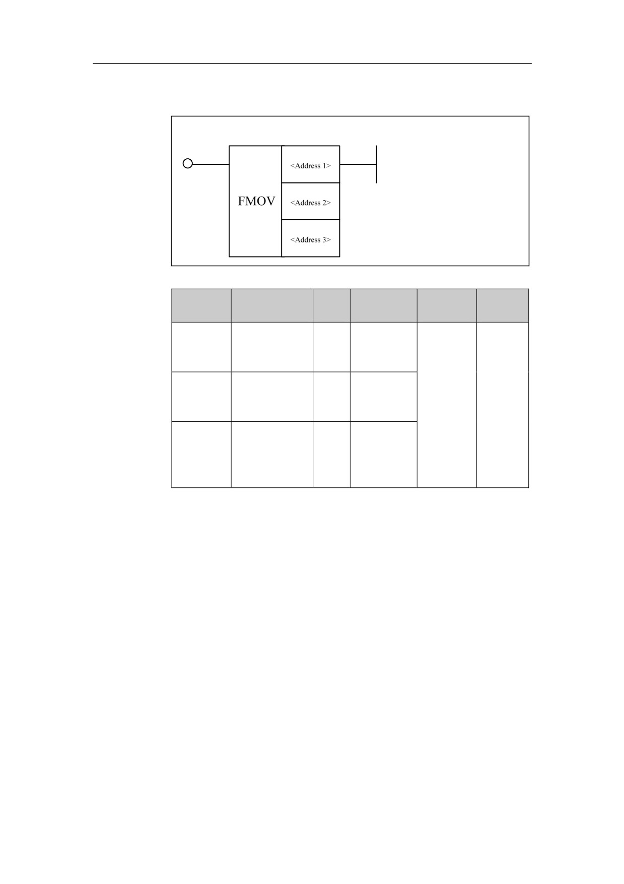
Multiple Moving Data FMOV
Format
Parameter
Data
Storage
Explanatio
Properti
Parameter
form
type
area
n
es
<Address
INT
Y, G, R, W,
□□□□
1>
D, B
<Address
INT
Y, G, R, W,
Multiple
Pre ○
□□□□
2>
D, B
moving
Post ×
data.
INT
Constant, X,
<Address
□□□□
Y, F, G, R,
3>
W, D, P, B
Function
Multiple moving data. Source data is transferred to a space that from the
starting address of destination to ending address of destination.
Parameter
Parameter 1: starting address of destination
Parameter 2: ending address of destination
Parameter 3: source data
Example
111
4. Basic function module
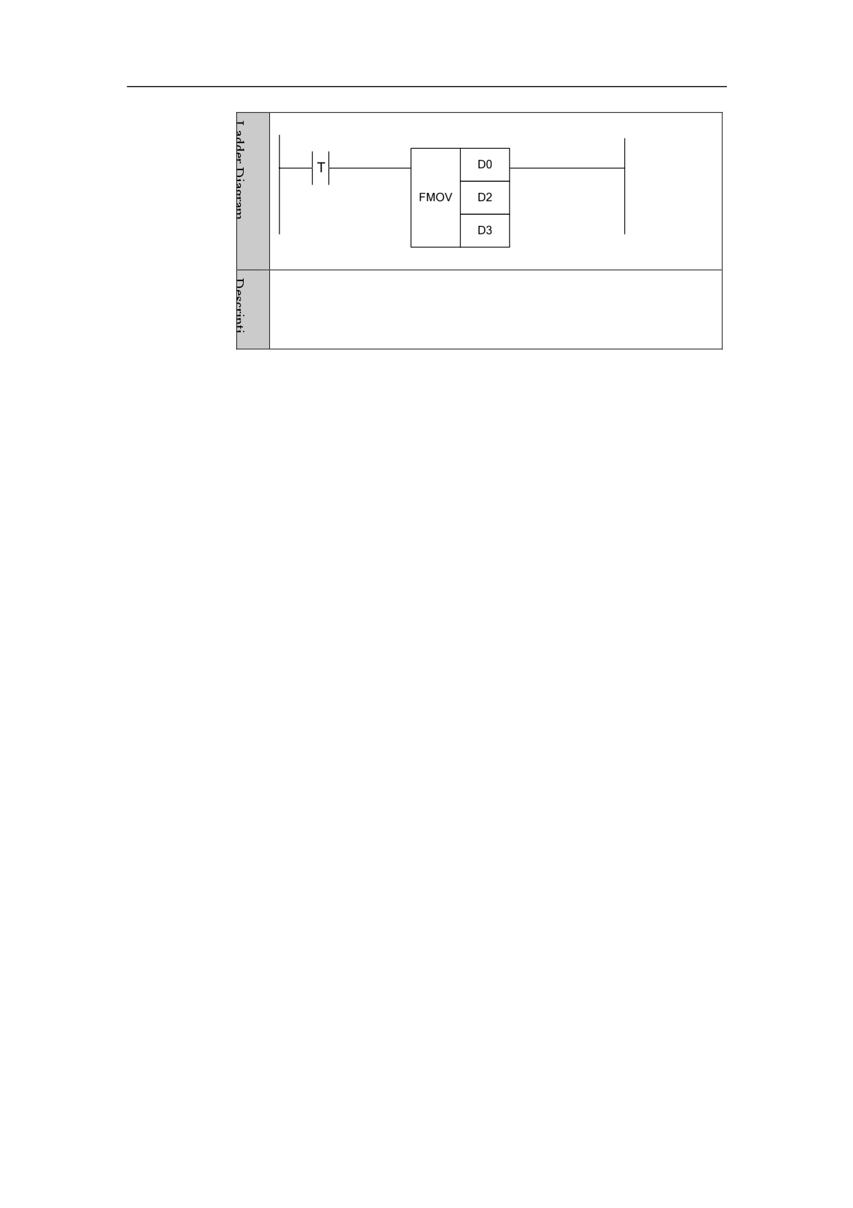
D3 data is assigned to the position that from D0 to D2.
112
4. Basic function module
Data Exchange XCH
Format
D1ƑƑƑ
D2ƑƑƑ
XCH
D3ƑƑƑ
D4ƑƑƑ
Parameter
Data
Storage
Properti
Parameter
Explanation
form
type
area
es
<Address1
INT
Constant
□□□□
>
<Address
INT
G, R, W, D,
□□□□
2>
B
It is used to
exchange
INT
Constant
Pre ○
<Address
data.
□□□□
3>
<Address
INT
G, R, W, D,
Post ×
□□□□
4>
B
Function
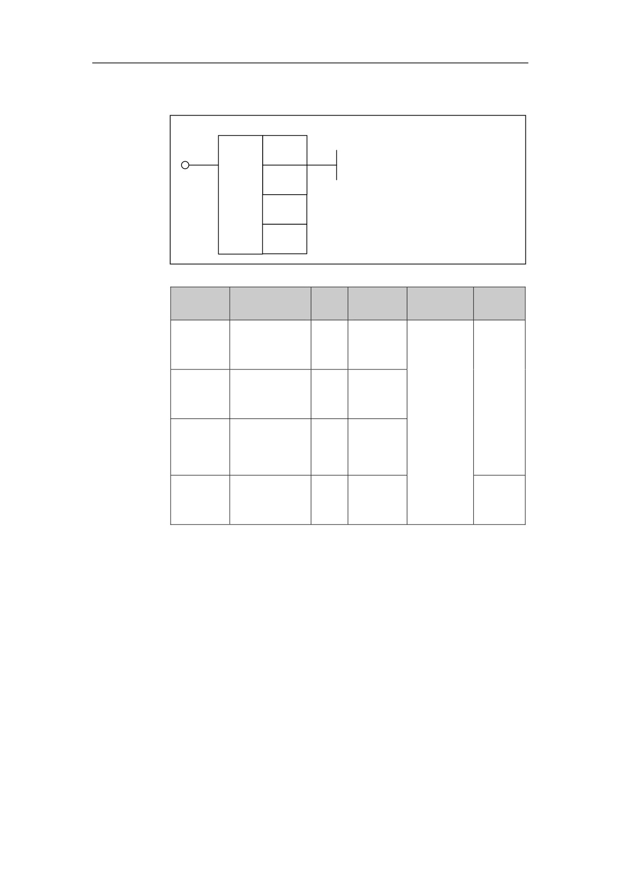
Data exchange. Address of operand 2 is exchanged with address of operand 4.
The format of operand 2 can be represented by the value of address 1. 0
indicates the default register which is used in address 2, 1 indicates that B
register is used in address 2. In the same way, the format of operand 4 can be
represented by the value of address 3.
Parameter
Parameter 1: the format of operand 1. 0 indicates register, 1 indicates B
register, and
2 indicates P register. For example, parameter 1 is 0 and
parameter 2 is R10, which represent the address R10. Parameter 1 of 1, and
parameter 2 of R10, represent B register, and the data stored in group R10 of
register B. Parameter 1 of 2, and parameter 2 of R10, represent P register,
and the data stored in group R10 of register P.
113

4. Basic function module
Example
Exchange the data shifted to D1 with the data shifted to D2 in register
B.
114
4. Basic function module
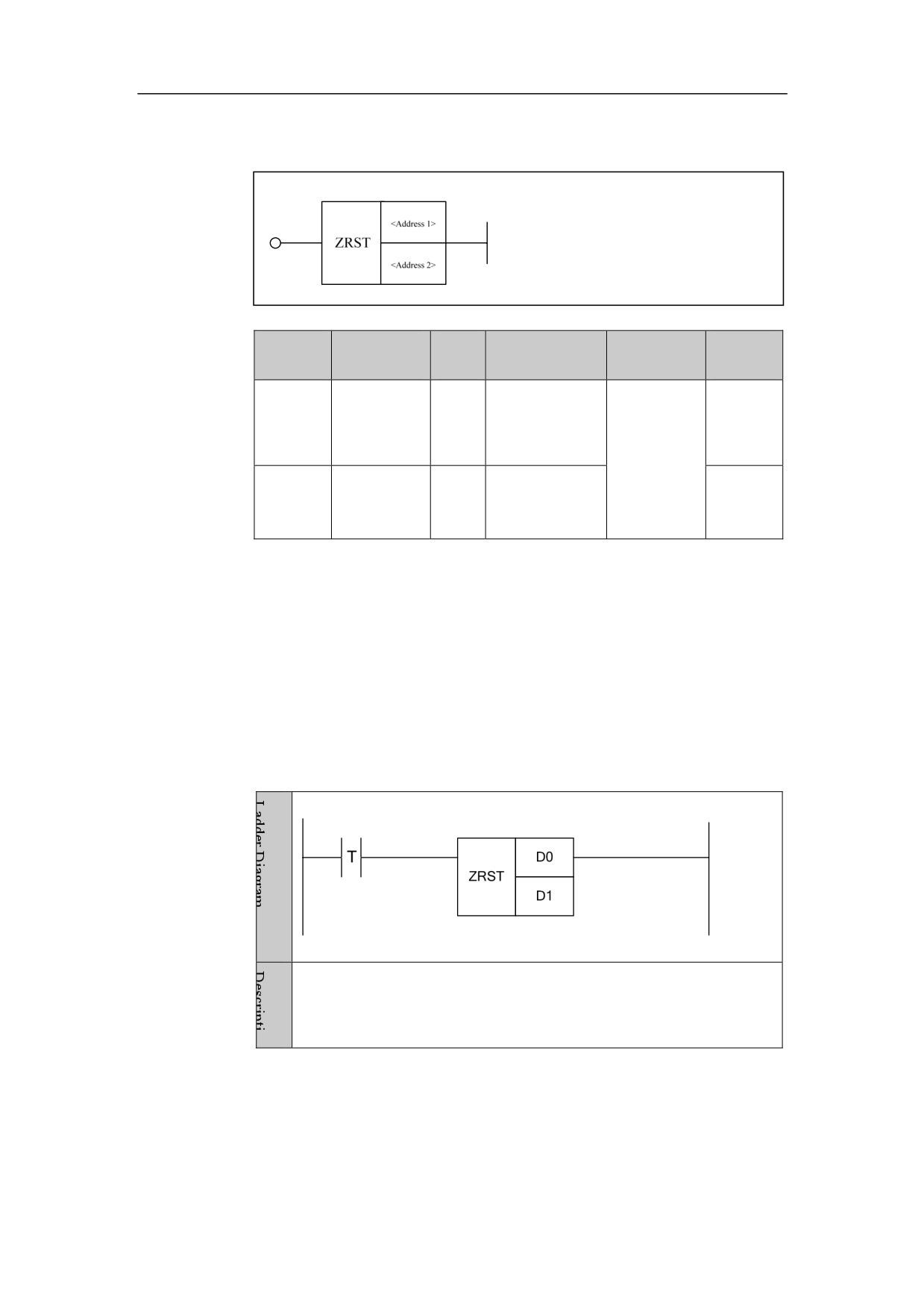
Data Reset ZRST
Format
Paramet
Parameter
Data
Properti
Storage area
Explanation
er
form
type
es
Y, G, R, W, D, B
Pre ○
<Addres
□□□.□
BOOL
s1>
Data reset
<Addres
Y, G, R, W, D, B
Post √
□□□.□
BOOL
s2>
Function
Data reset. Reset the data which is from starting address of operand to ending
address of operand.
Parameter
Parameter 1: starting address of operand
Parameter 2: ending address of operand
Example
0 is assigned to the position that from D0 to D1
115
4. Basic function module
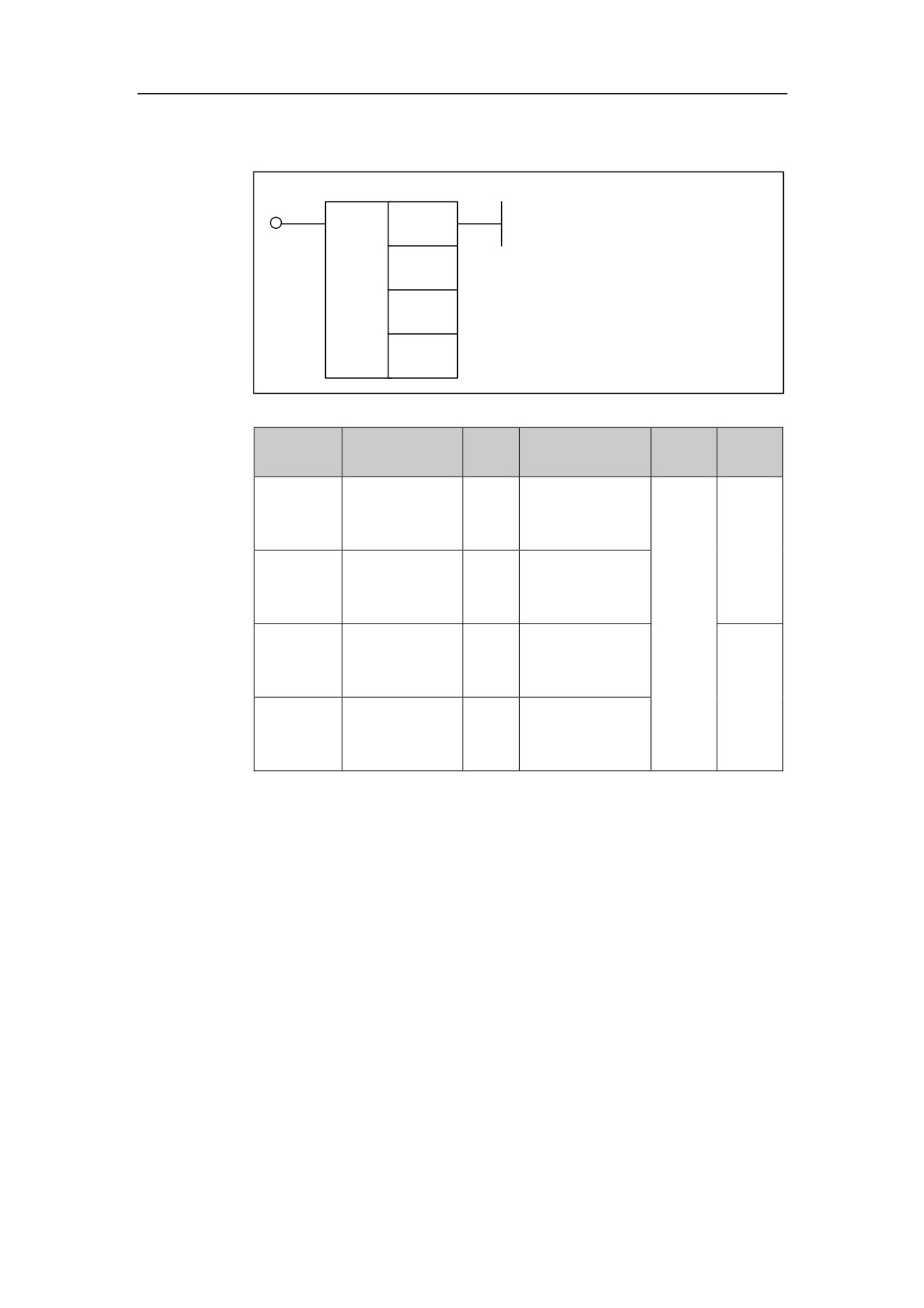
Encoding ENCO
Format
<Address 1>
<Address 2>
ENCO
<Address 3>
<Address 4>
Parameter
Data
Explan
Proper
Parameter
Storage area
form
type
ation
ties
<Address1
BOOL
X, Y, F, G, R, W,
□□□□. □
>
D, P, B
Pre ○
It
is
<Address2
INT
Constant
used
□□□□
>
for
overrid
<Address3
BOOL
X, Y, F, G, R, W,
e value
□□□□. □
>
D, P, B
conver
Post
sion
×
<Address4
BOOL
Y, G, R, W, D, P,
□□□□. □
>
B
Function
Encode. When there are 5 data bits (3, 5, 7, 8, 9) from the starting position of
encoded data, if source data is 3, the output is 00000001B, if source data is 5,
the output is 00000010B, if source data is 7, the output is 00000100B.
Parameter
Parameter 1: the starting position of encoded data, can use register D.
Parameter 2: number of coded data, can be constant.
Parameter 3: source data, can be register R and D.
Parameter 4: Output address of destination data, can be register R and D.
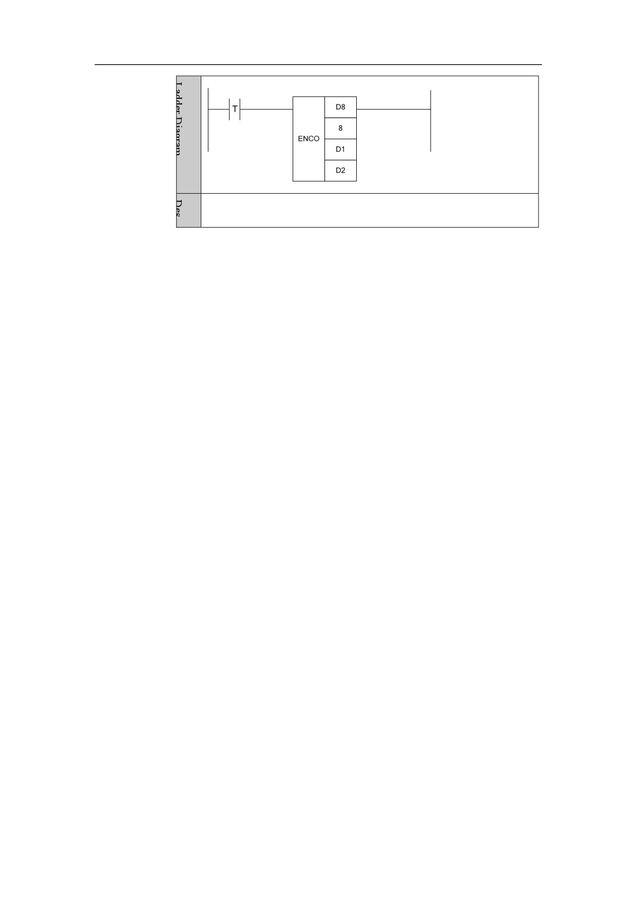
Example
116
4. Basic function module
After being encoded, data in D1 is output to D2.
117
4. Basic function module
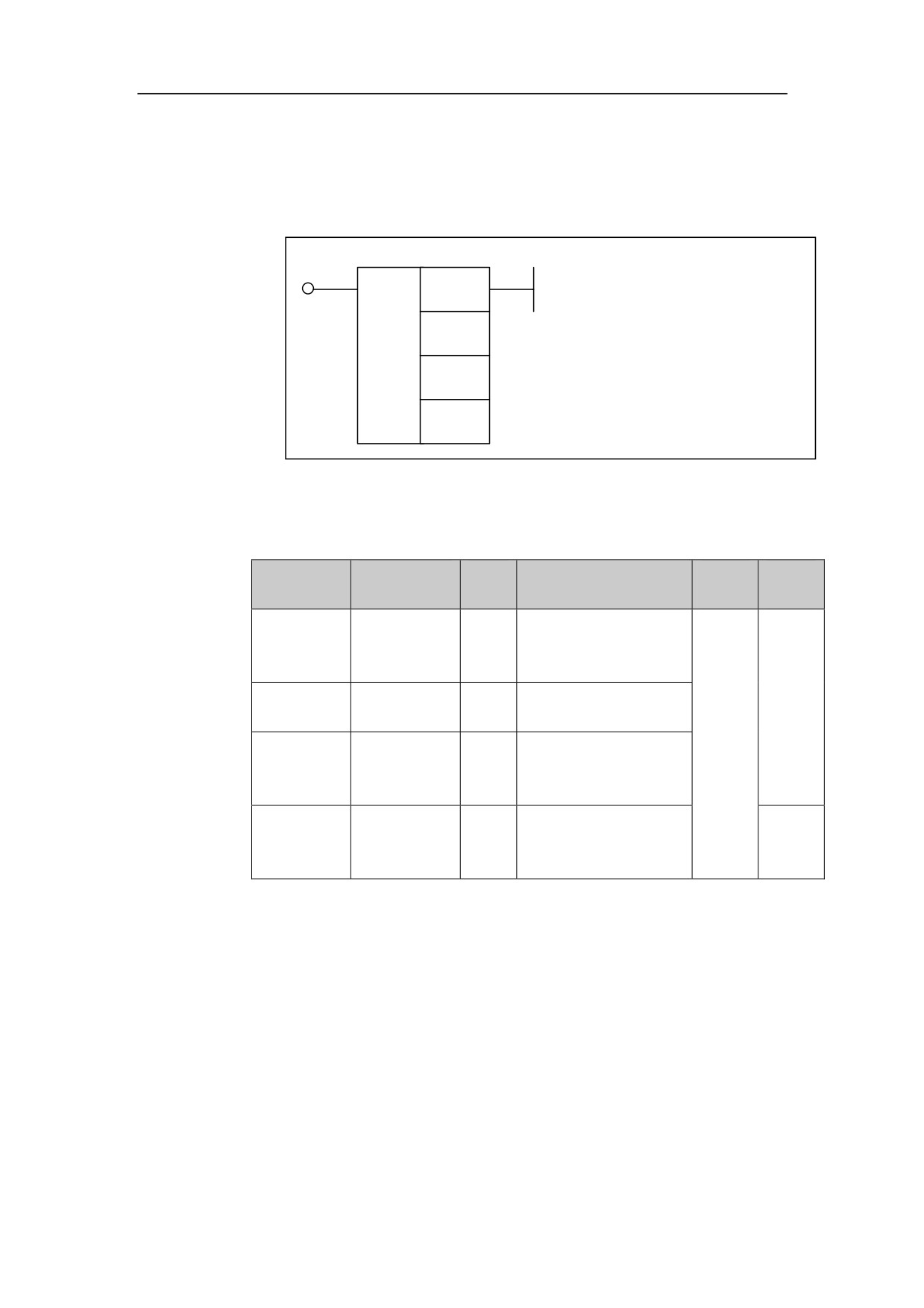
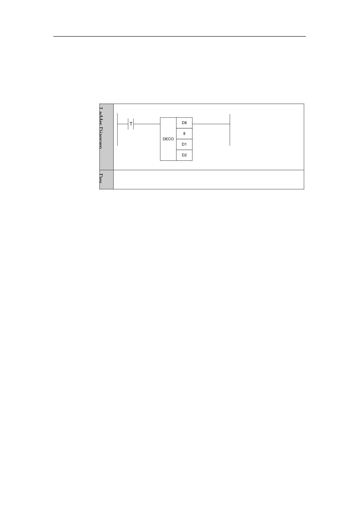
Decoding DECO
Format
<Address 1>
<Address 2>
DECO
<Address 3>
<Address 4>
Parameter
Data
Explan
Proper
错误!
Parameter
Storage area
form
type
ation
ties
□□□□.
BOOL
X, Y, F, G, R, W, D, P, B
Pre√
<Address1>
□
It
is
used
<Address 2>
□□□□
INT
Constant
for
overrid
□□□□.
BOOL
X, Y, F, G, R, W, D, P, B
<Address 3>
e value
□
conver
sion
□□□□.
BOOL
Y, G, R, W, D, P, B
Post×
<Address 4>
□
Function
Decoding, which is reversed to encoding.
Parameter
Parameter 1: the starting position of decoded data, can use register D.
Parameter 2: number of decoded data, can be constant.
118
4. Basic function module
Parameter 3: source date, can be register R and D
Parameter 4: Output address of destination data, can be register R and D.
Example
After being decoded, the data in D1 is output to D2
119
4. Basic function module
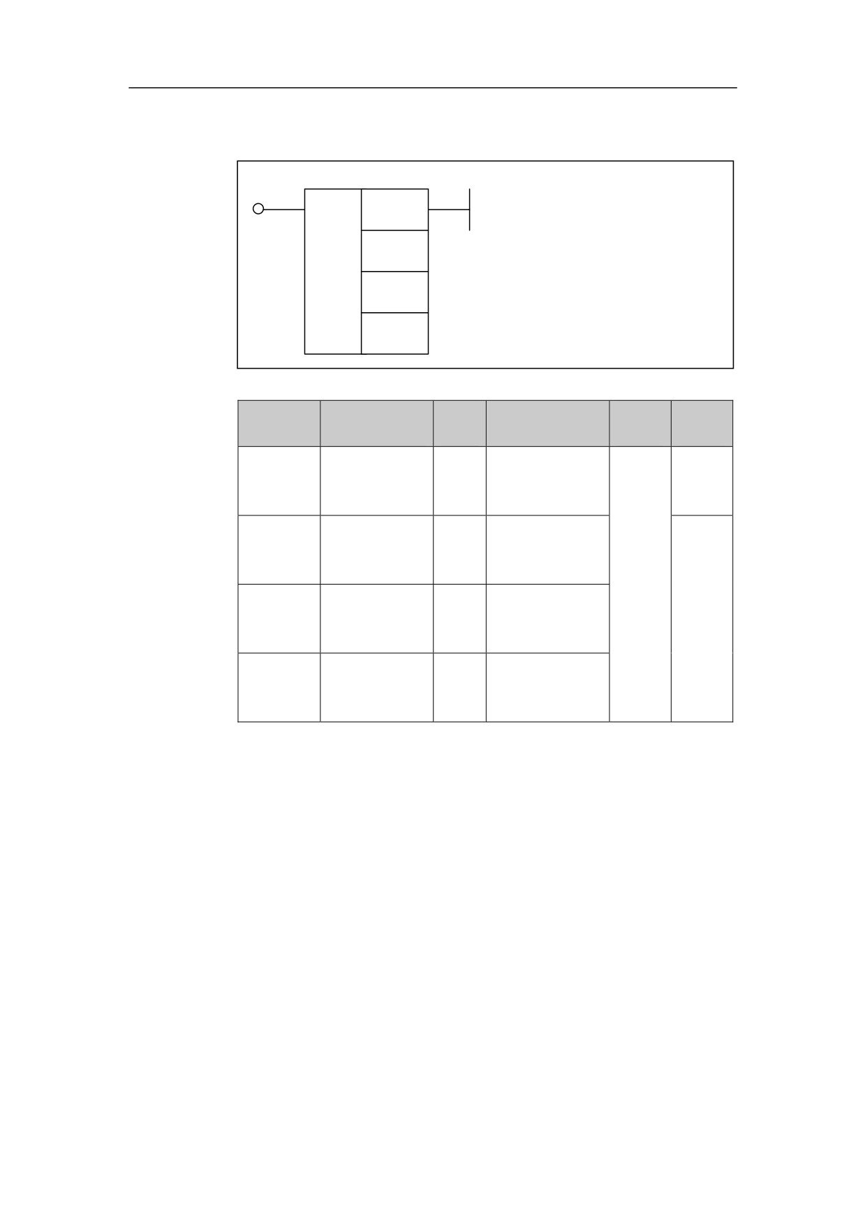
Transformation COD
Format
<Address 1>
<Address 2>
COD
<Address 3>
<Address 4>
Parameter
Data
Explan
Proper
Parameter
Storage area
form
type
ation
ties
<Address1
BOOL
X, Y, F, G, R, W,
Pre
□□□□. □
>
D, P, B
√
It
is
<Address
used
□□□□
INT
Constant
2>
for
overrid
<Address
BOOL
X, Y, F, G, R, W,
e value
Post
□□□□. □
3>
D, P, B
conver
×
sion
<Address
BOOL
Y, G, R, W, D, P,
□□□□. □
4>
B
Function
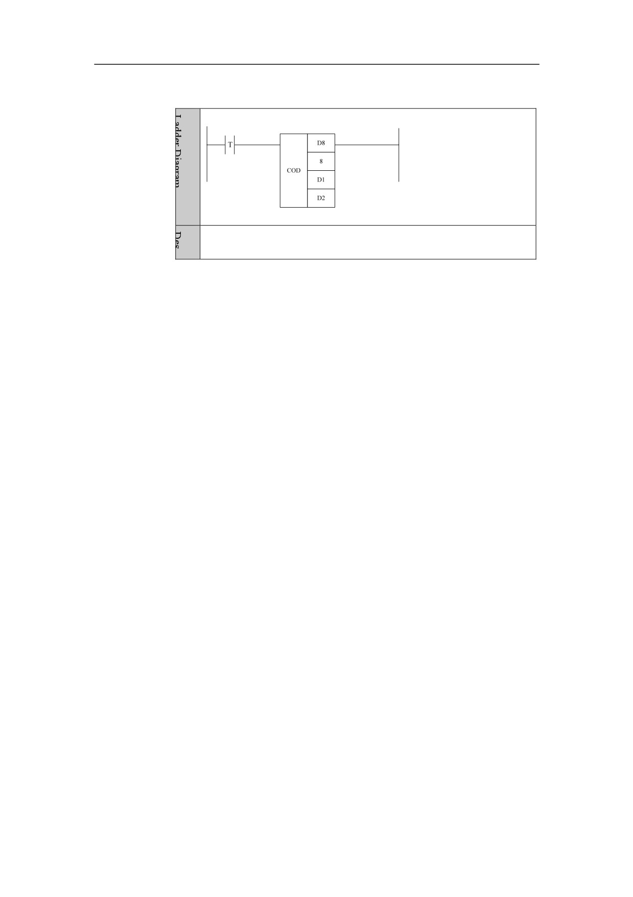
Code transformation. It is mainly used for override value conversion. Take
spindle overrise as an example, there are 8 data bits (50, 60, 70, 80, 90, 100, 110,
120) from D0; when source data is 0, the data transformed is 50; when source
data is 1, the data transformed is 60; when source data is 2, the data transformed
is 70.
Parameter
Parameter 1: the starting position for transforming data, can be register D.
Parameter 2: the number of data being transformed, which can be constant.
Parameter 3: source data, can be register R and D.
Parameter 4: output address of the target data, can be register R and D.
120
4. Basic function module
Example
After being transcoded, the data in D1 is output to D2.
121
4. Basic function module
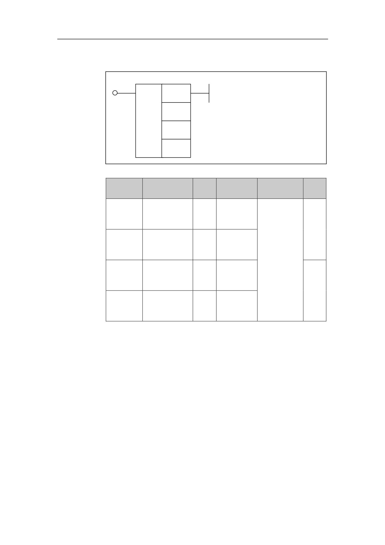
Data Search SER
format
<Address 1>
<Address 2>
SER
<Address 3>
<Address 4>
Parameter
Data
Storage
Prop
Parameter
Explanation
form
type
area
erties
<Address
INT
X, Y, F, G, R,
□□□□
1
>
W, D, P, B
When data
Pre
has been
√
<Address
found, the
□□□□
INT
Constant
2
>
output is 1;
when data
<Address
INT
X, Y, F, G, R,
hasn’t
□□□□
3
>
W, D, P, B
been
Post
found, the
×
<Address
INT
Y, G, R, W,
output is 0.
□□□□
4
>
D, P, B
Function
To search data. Search a data in a statement list. When the data is found, the
output is 1; when the data is not found, the output is 0.
Parameter
Parameter 1: searching address, can only be register D.
Parameter 2: searching range, can be constant.
Parameter 3: the data to be searched, can be constant and register X, Y, K, L, F, G,
R, D.
Parameter 4: the output address of searched result, can only be register D.
122
4. Basic function module
Example
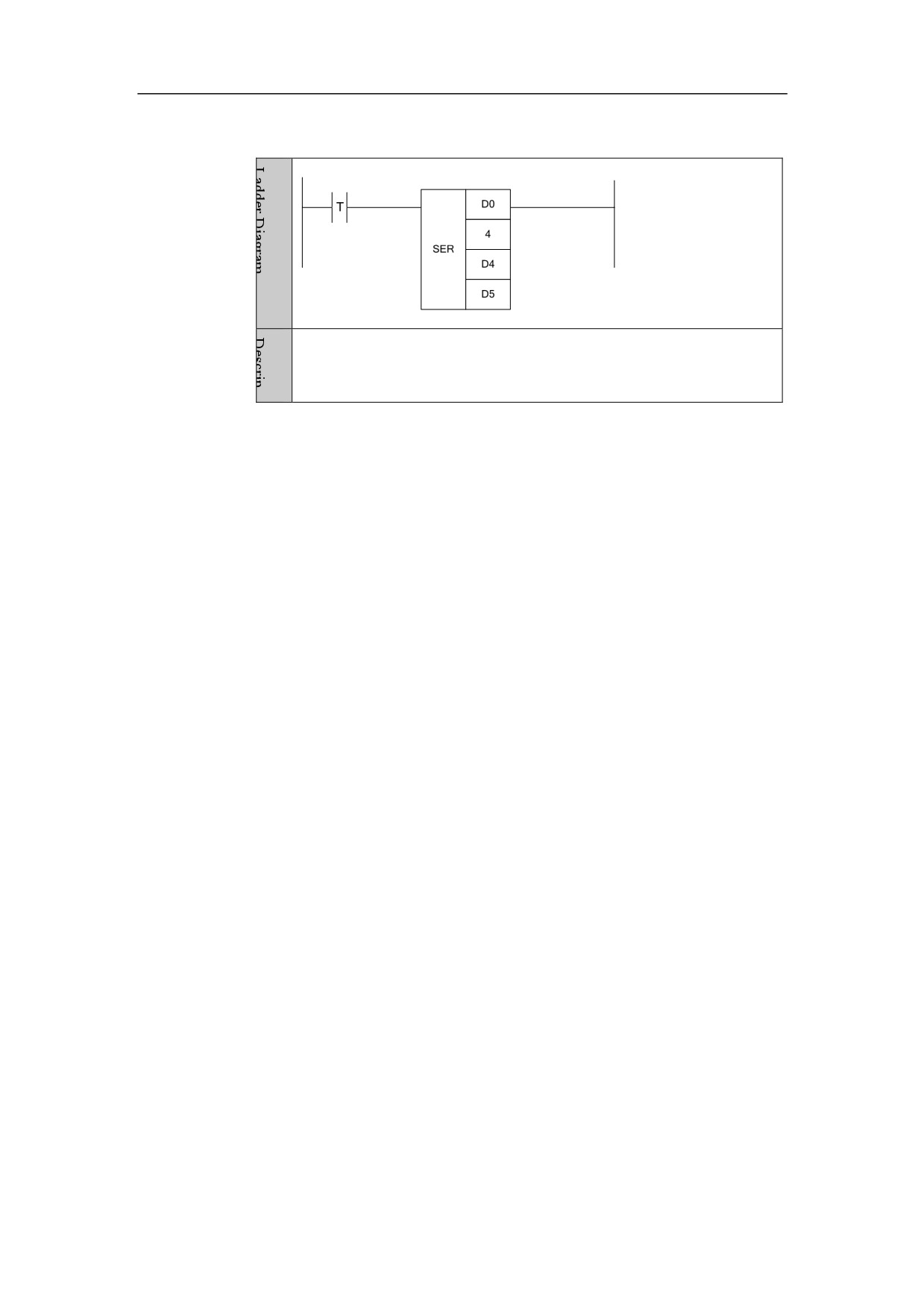
Search the data of D4 in the four data from D0, and output the position
of the data being found to D5.
123
4. Basic function module
Register Merging ASSEM
Format
Parameter
Data
Explanatio
Proper
Parameter
Storage area
form
type
n
ties
<Address
INT
X, Y, F, G, R,
□□□□
1
>
W, D, P, B
To merge
the data
Pre√
<Address
of several
□□□□
INT
Constant
2
>
registers
into one
<Address
INT
G, W, D, B
register.
□□□□
Post×
3
>
Function
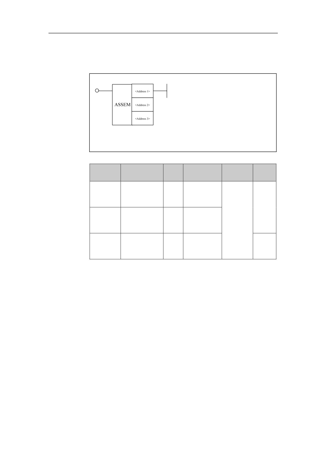
To merge several register data into one register.
parameter
Parameter 1: source data.
Parameter 2: quantity of source registers, can only be constant.
Parameter 3: target address, can be register G, W, D, B.
Example
124
4. Basic function module
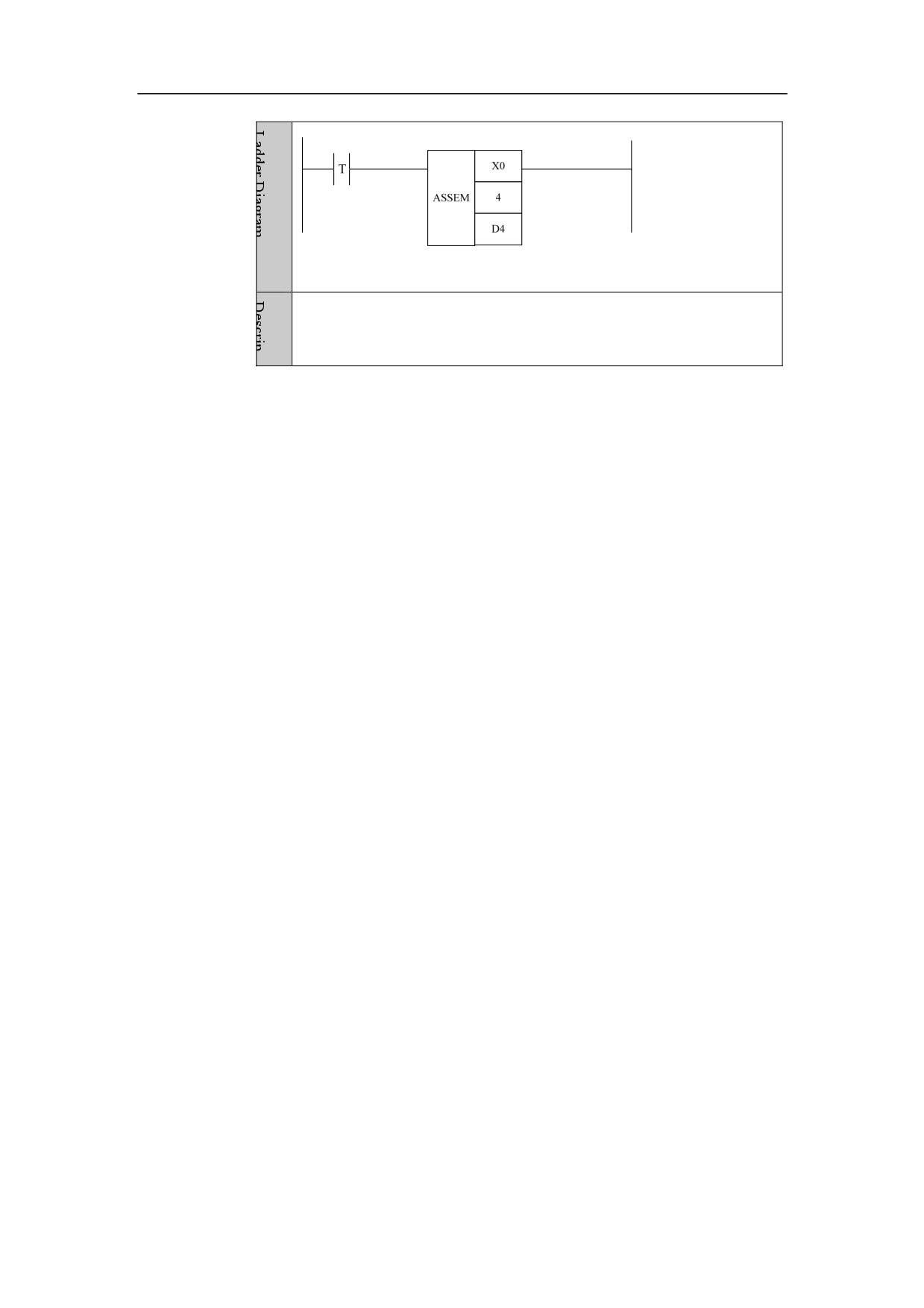
Merge the four data which are from X0 into one data (that is, merge
four 8-bit data into one 32-bit data)
125
4. Basic function module
Register Decomposition DISAS
Format
Parameter
Data
Storage
Proper
Parameter
Explanation
form
type
area
ties
<Address
INT
F, G, W, D,
□□□□
1
>
P, B
To break up
Pre√
the data of
<Address
□□□□
INT
Constant
one register
2
>
into several
registers.
<Address
INT
Y, G, R, W,
□□□□
Post×
3
>
Function
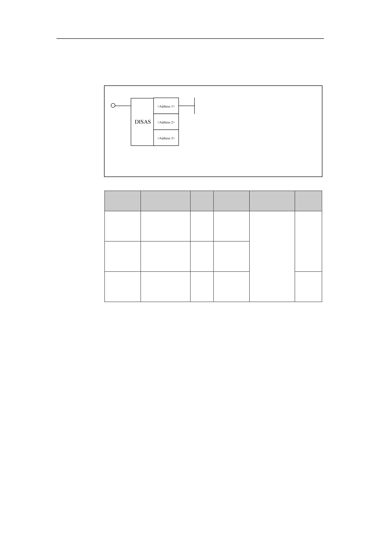
To break up the data of one register into several registers.
Parameter
Parameter 1: source address.
Parameter 2: number of source registers, can only be constant.
Parameter 3: target address, can be register Y, G, R, W.
Example
126
4. Basic function module
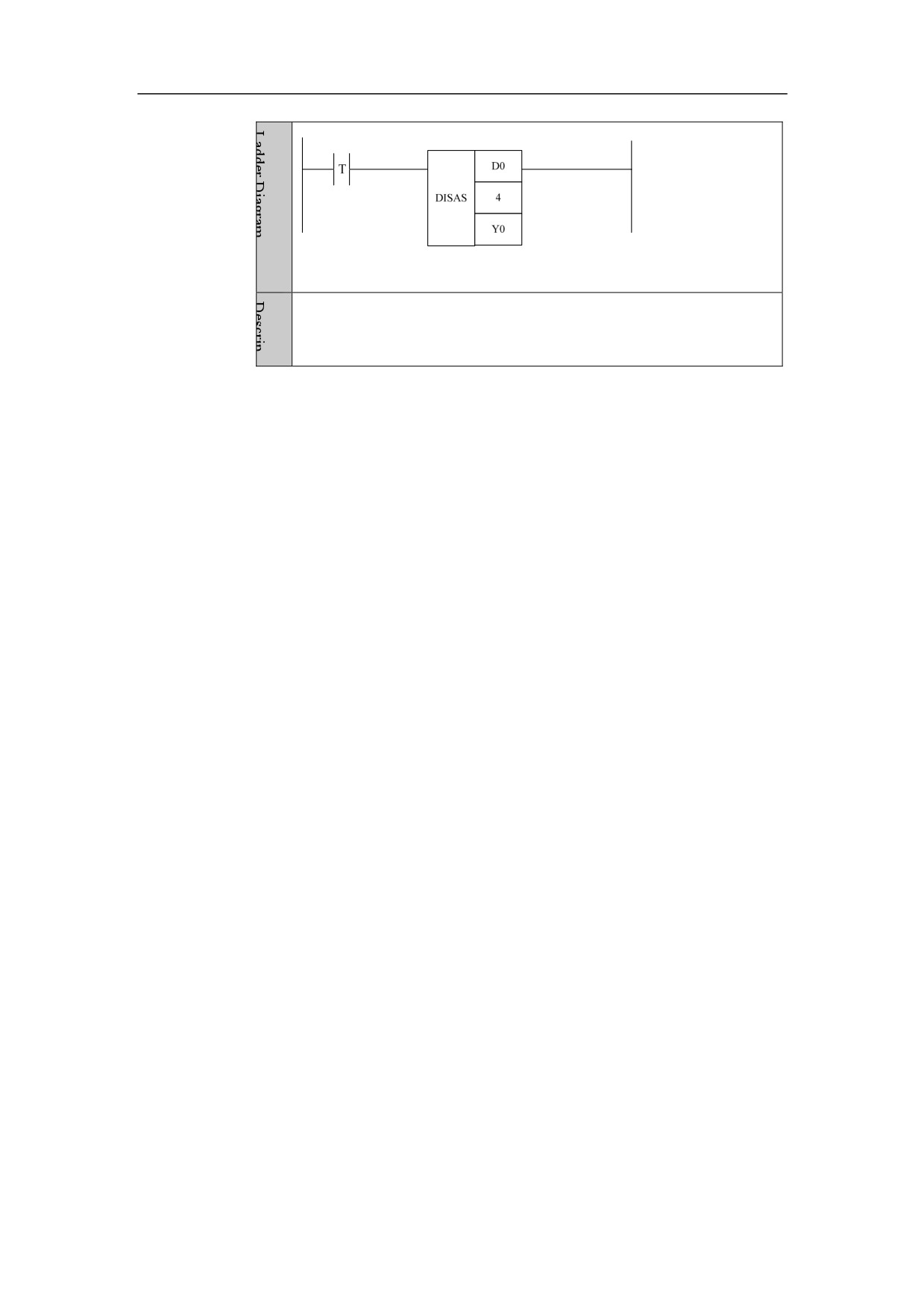
Break up the data of D0 into the four data which are from Y0 (that is,
one 32-bit data is broken up into 4 8-bit data).
127
4. Basic function module
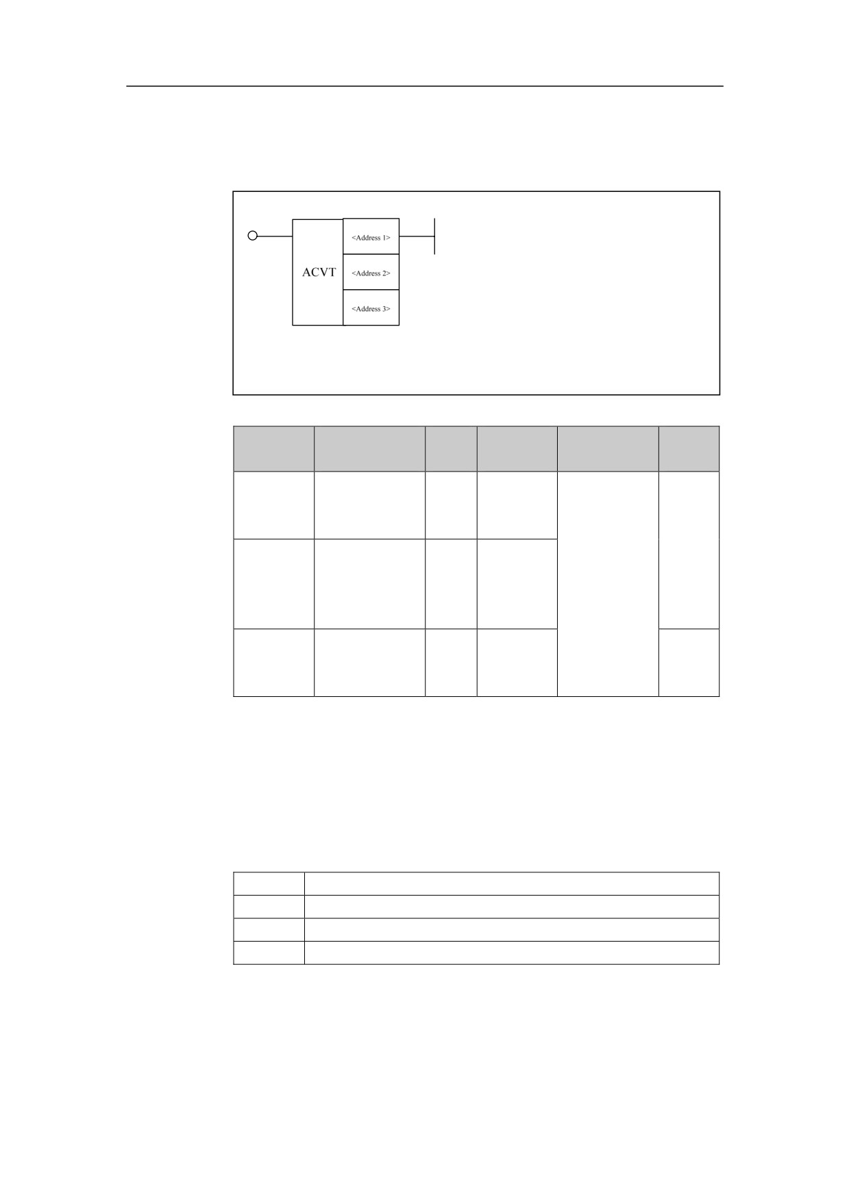
Area Conversion ACVT
Format
Parameter
Data
Storage
Proper
Parameter
Explanation
form
type
area
ties
<Address
INT
P
□□□□
Convert
1
>
source data
which follows
Pre√
X, Y, F, G,
<Address
a
certain
□□□□
INT
R, W, D, P,
2
>
proportional
B
relationship
to
target
<Address
INT
Y, G, R, W,
□□□□
data.
Post×
3
>
D, B
Function
Convert source data which follows a certain proportional relationship to target
data.
parameter
Parameter 1: Address of proportional relationship.
0
Minimum value of source data
1
Maximum value of source data
2
Minimum value of target data
3
Maximum value of target data
Parameter 2: number of source registers.
Paramter 3: target address, can be register Y, G, R, W, D, B;
128
4. Basic function module
Example
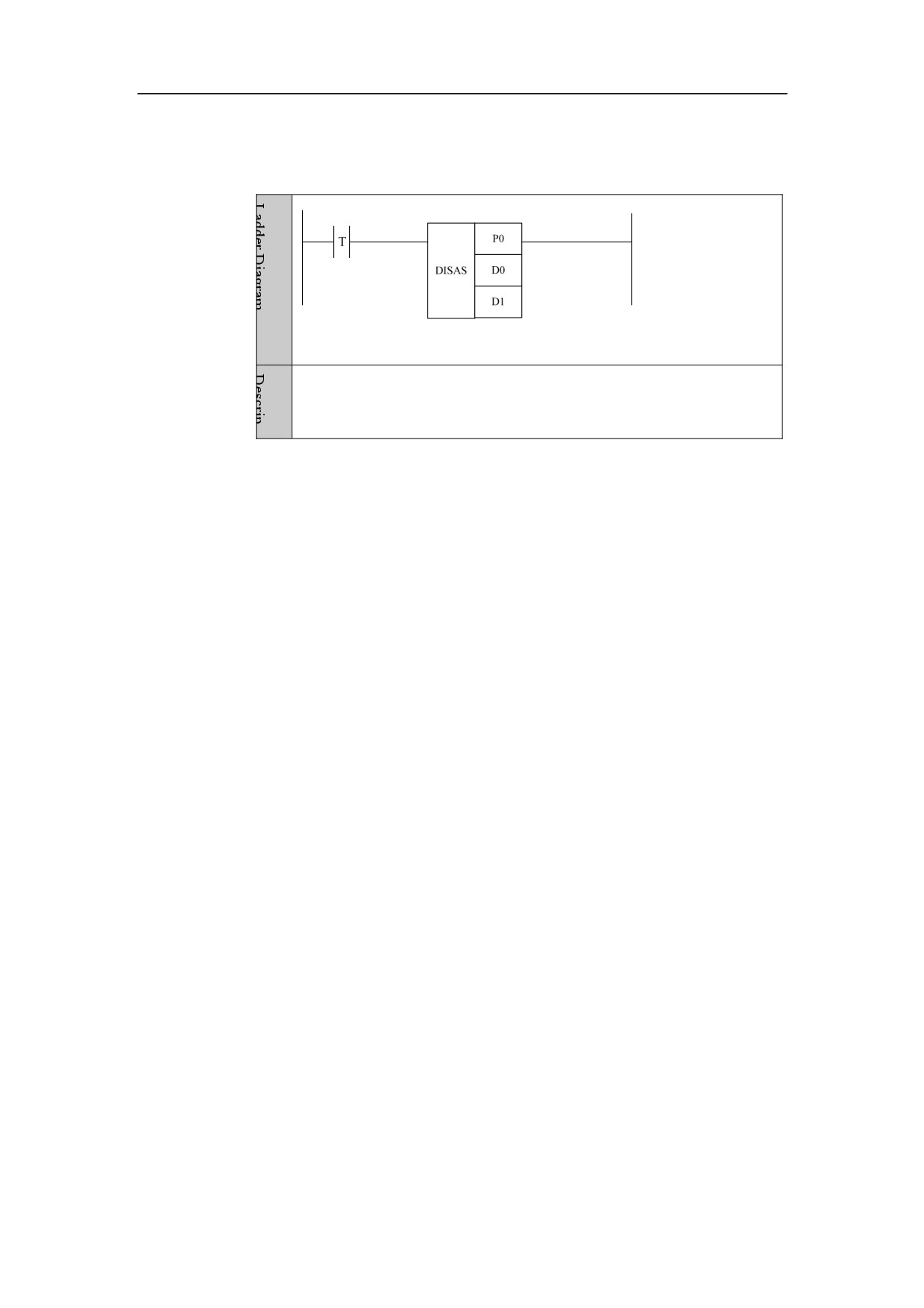
Convert D0 data which follows a certain proportional relationship to
D1. D1=(D0-P0)*(P3-P2)/(P1-P0)+P0;
129
4. Basic function module
Alternate Output ALT
Format
Paramet
Parameter
Data
Properti
Storage area
Explanation
er
form
type
es
Pre √
<Addres
□□□□
INT
Constant
Number
s 1>
Post √
Function
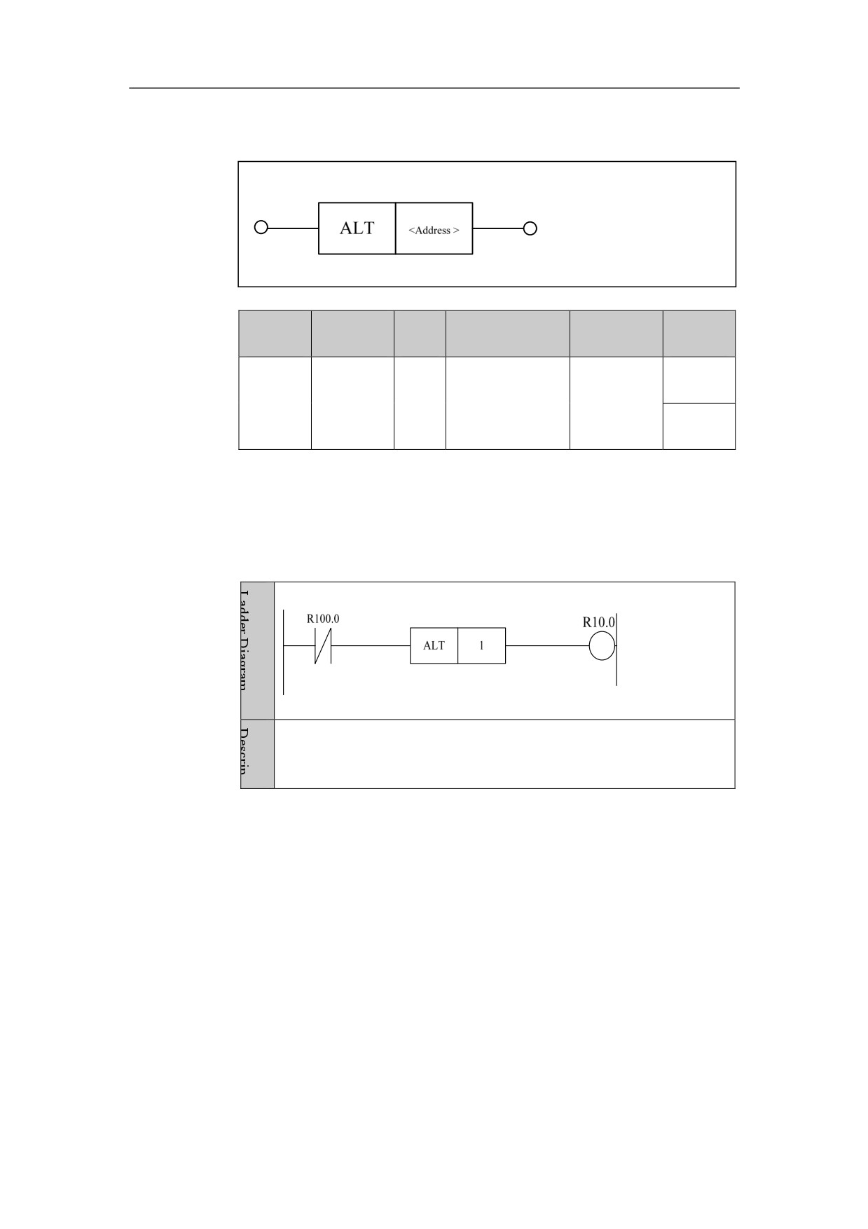
Alternate output. The component keeps its output status, until it encounters
the rising edge, then the output status changes (change from 0 to 1, or 1 to 0).
Example
When R100.0 is turned off from turned on, the module 1 changes the
output status.
130
4. Basic function module
Fetch Rising Edge PLS
Format
Paramet
Parameter
Data
Properti
Storage area
Explanation
er
form
type
es
Rising edge
Pre ○
<Addres
□□□□
INT
Constant
module
s 1>
number
Post √
Function
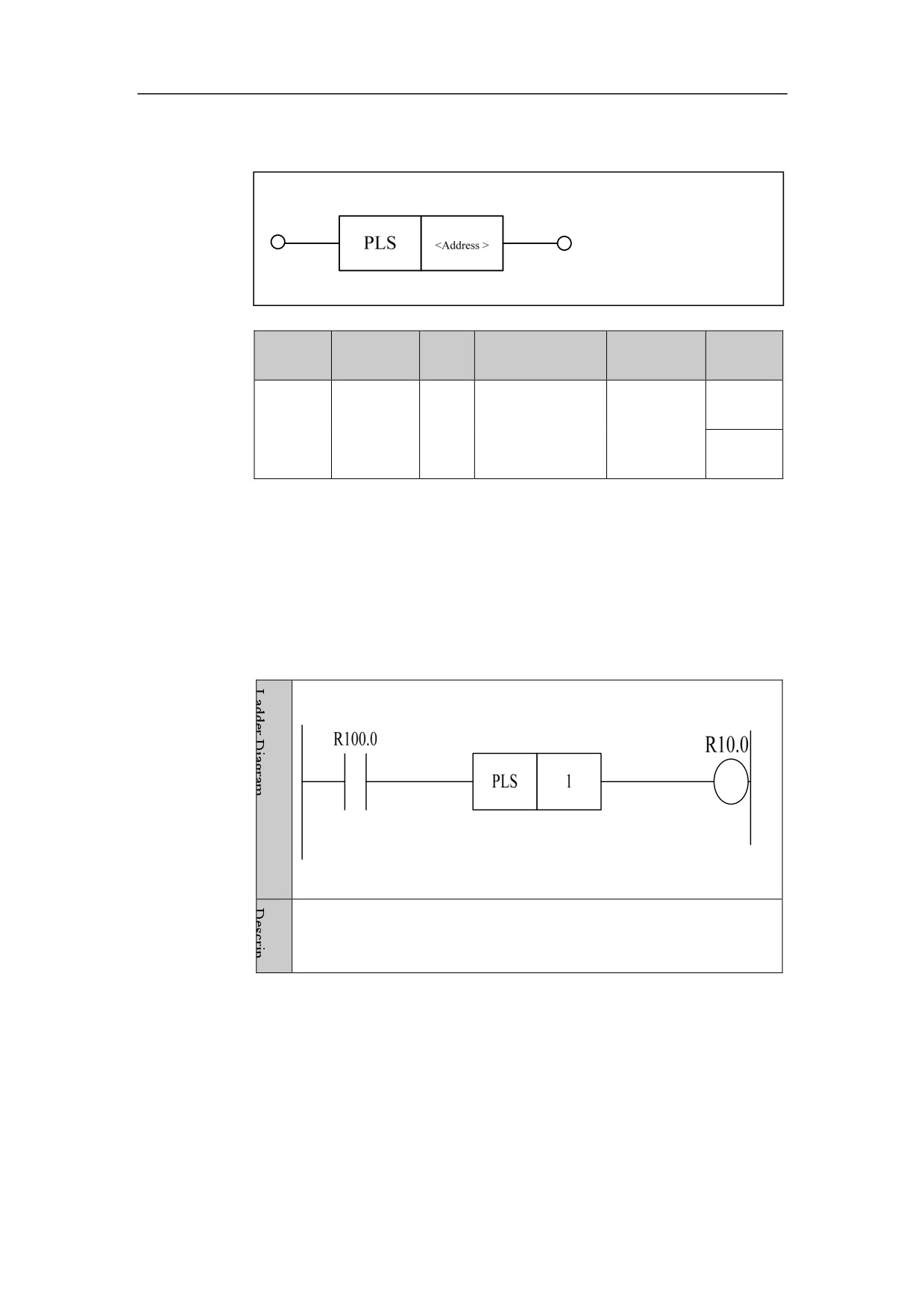
Get the status of the current line or current position, and get its trigger signal of
the rising edge.
Set the input signal to 1 in the current scan cycle of the rising edge signal.
(Note the difference between the trigger component of rising edge for basic
component and this function). This function is suitable for the situations where
the rising edge status needs to be detected.
Example
When R100.0 status is changed from 0 to 1, fetch its rising edge status
and the output of R10.0 is 1.
131
4. Basic function module
Fetch Falling edge PLF
Format
Paramet
Parameter
Data
Properti
Storage area
Explanation
er
form
type
es
Falling edge
Pre ○
<Addres
□□□□
INT
Constant
module
s 1>
number
Post √
Function
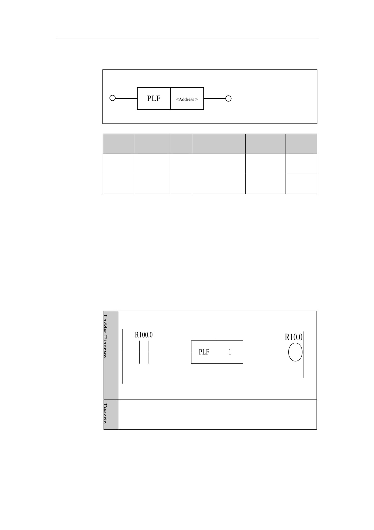
Get the status of the current line or current position, and get its trigger signal of
the falling edge.
Set the input signal to 1 in the current scan cycle of the falling edge signal. (Note
the difference between the trigger component of falling edge for basic
component and this function). This function is suitable for the situations where
the falling edge status needs to be detected.
Example
When R100.0 status is changed from 1 to 0, fetch its falling edge status
and the output of R10.0 is 1.
132
HNC-8-PLC Component specification
4. Basic function module
Points Transformation PTN
Format
Parameter
Data
Storage
Explanatio
Properti
Parameter
form
type
area
n
es
Y, G, R, W,
<Address 1>
□□□□
BOOL
D, B
X, Y, F, G, R,
□□□□.
<Address 2>
BOOL
W, D, P, T,
□
C, B
<Address 3>
□□□□
INT
Constant
Pre ○
When the
X, Y, F, G, R,
□□□□.
point is
<Address 4>
BOOL
W, D, P, T,
□
effective,
C, B
the
correspon
<Address 5>
□□□□
INT
Constant
ding
number is
X, Y, F, G, R,
□□□□.
generated
<Address 6>
BOOL
W, D, P, T,
□
C, B
<Address 7>
□□□□
INT
Constant
Post ×
X, Y, F, G, R,
□□□□.
<Address 8>
BOOL
W, D, P, T,
□
C, B
<Address 9>
□□□□
INT
Constant
133
HNC-8-PLC Component specification
4. Basic function module
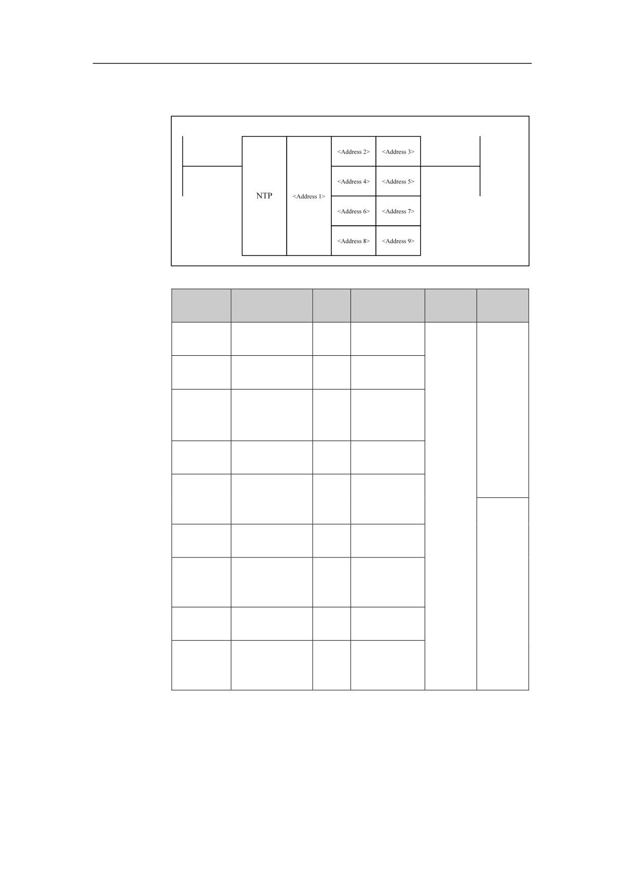
Function
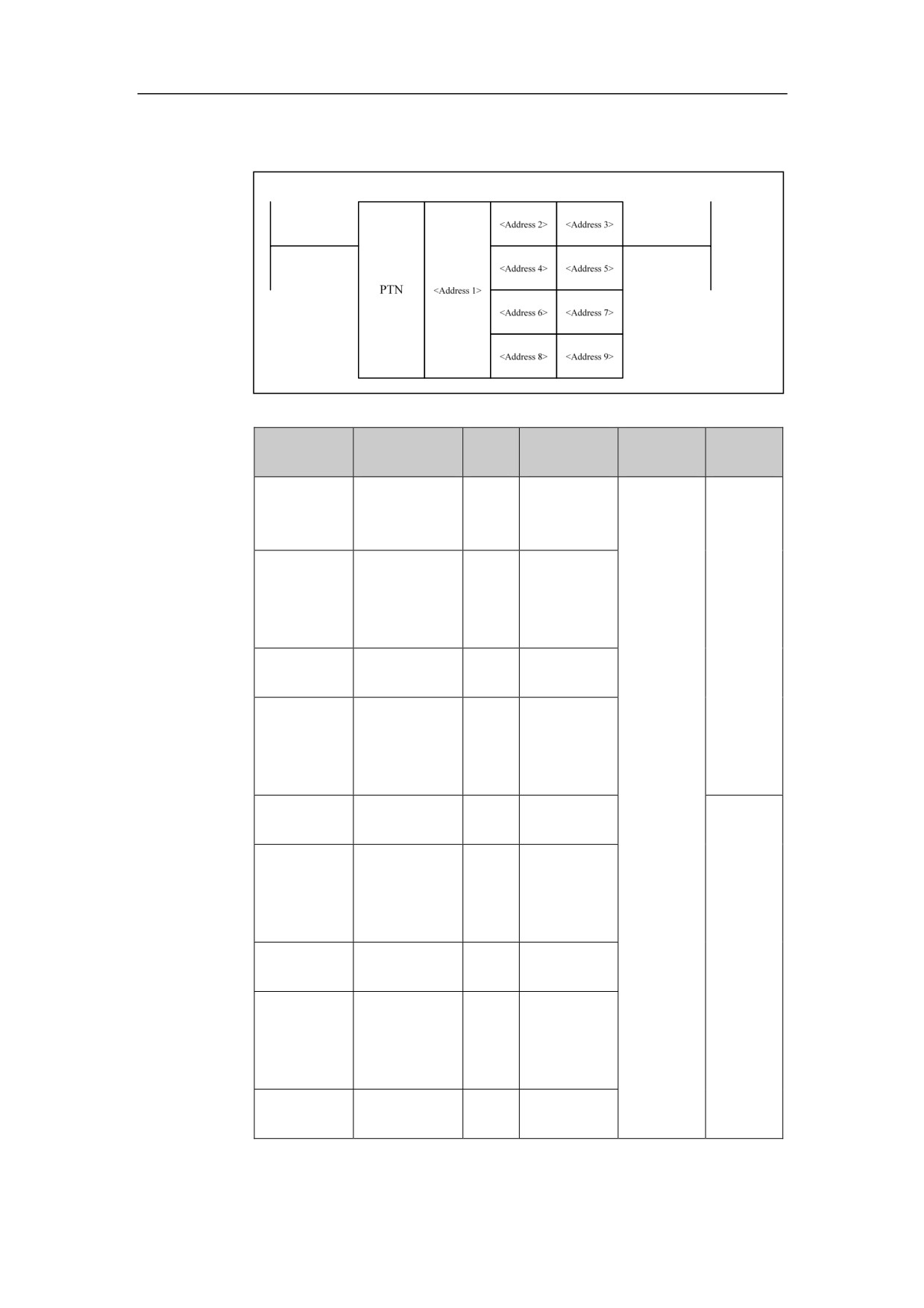
To build the corresponding relationship between points and
numbers. When the point is effective, the corresponding
number is generated.
Parameter 1: the destination address.
Parameter 2: point 1
Parameter
Parameter 3: number 1
Parameter 4: point 2
Parameter 5: number 2
Parameter 6: point 3
Parameter 7: number 3
Parameter 8: point 4
Parameter 9: number 4
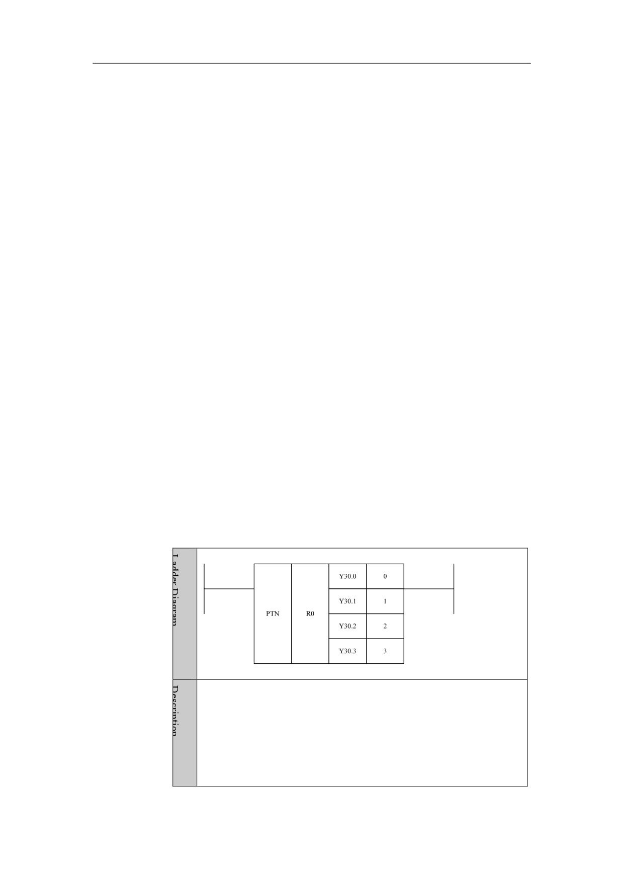
Example
When Y30.0 is effective, R0=0.
When Y30.1 is effective, R0=1.
When Y30.2 is effective, R0=2.
When Y30.3 is effective, R0=3.
134
HNC-8-PLC Component specification
4. Basic function module
Number Conversion NTP
Format
Parameter
Data
Explanat
Properti
Parameter
Storage area
form
type
ion
es
<Address
Y, G, R, W, D,
□□□□
BOOL
1>
B
<Address
□□□□
INT
Constant
2>
X, Y, F, G, R,
<Address
Pre ○
□□□□. □
BOOL
W, D, P, T, C,
3>
B
<Address
□□□□
INT
Constant
4>
X, Y, F, G, R,
<Address
□□□□. □
BOOL
W, D, P, T, C,
5>
B
<Address
INT
Constant
□□□□
6>
X, Y, F, G, R,
<Address
□□□□. □
BOOL
W, D, P, T, C,
7>
Post ×
B
<Address
INT
Constant
□□□□
8>
X, Y, F, G, R,
<Address
□□□□. □
BOOL
W, D, P, T, C,
9>
B
Function
To build the corresponding relationship between numbers and points. The
point signal corresponding to the number in Parameter 1 is
generated.
135
HNC-8-PLC Component specification
4. Basic function module
Parameter 1: the address of source data
Parameter 2: number 1
Parameter 3: point 1
Parameter
Parameter 4: number 2
Parameter 5: point 2
Parameter 6: number 3
Parameter 7: point 3
Parameter 8: number 4
Parameter 9: point 4
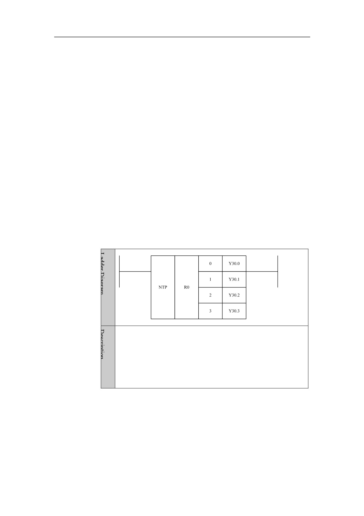
Example
When R0=0, Y30.0 is effective.
When R0=1, Y30.1 is effective.
When R0=2, Y30.2 is effective.
When R0=3, Y30.3 is effective.
136
HNC-8-PLC Component specification
4. Basic function module
Part Count PARTCNT
Format
Paramet
Parameter
Data
Properti
Storage area
Explanation
er
form
type
es
When
Pre ○
condition
is
satisfied,
1 is
<Addres
□□□□
INT
Constant
added to part
s 1>
count
of
Post √
<Address
1>
channel.
Function
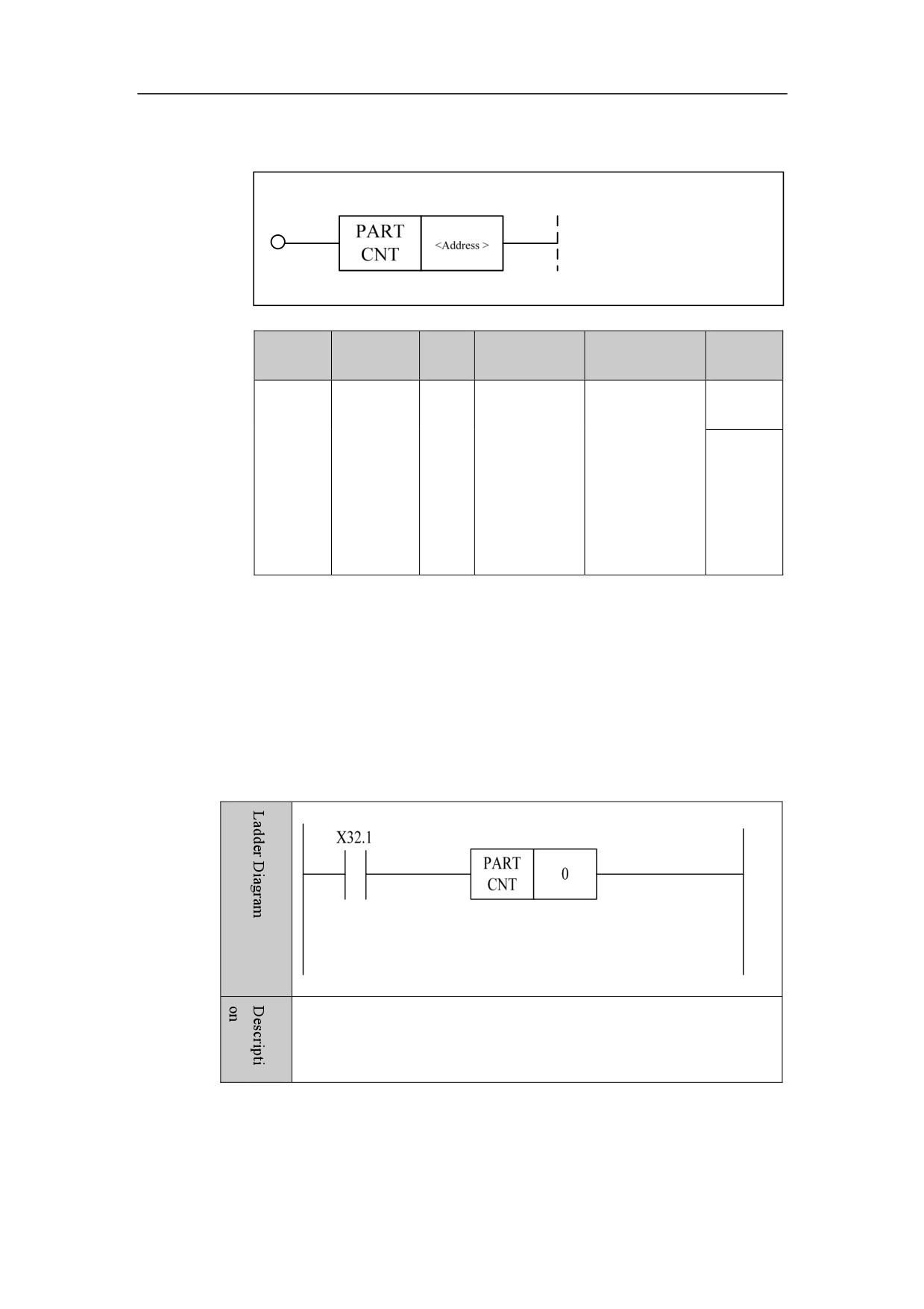
To count machined parts.
Parameter
Parameter 1: channel number
Example
When 32.1 is turned on, 1 is added to the part count of channel 0.
137
HNC-8-PLC Component specification
4. Basic function module
Part-counting Clear PARTCLR
Format
Paramet
Parameter
Data
Storage
Properti
Explanation
er
form
type
area
es
When condition
Pre ○
is satisfied, part
<Addres
count
of
□□□□
INT
Constant
s 1>
<Address
>
Post √
channel
is
cleared to zero.
Function
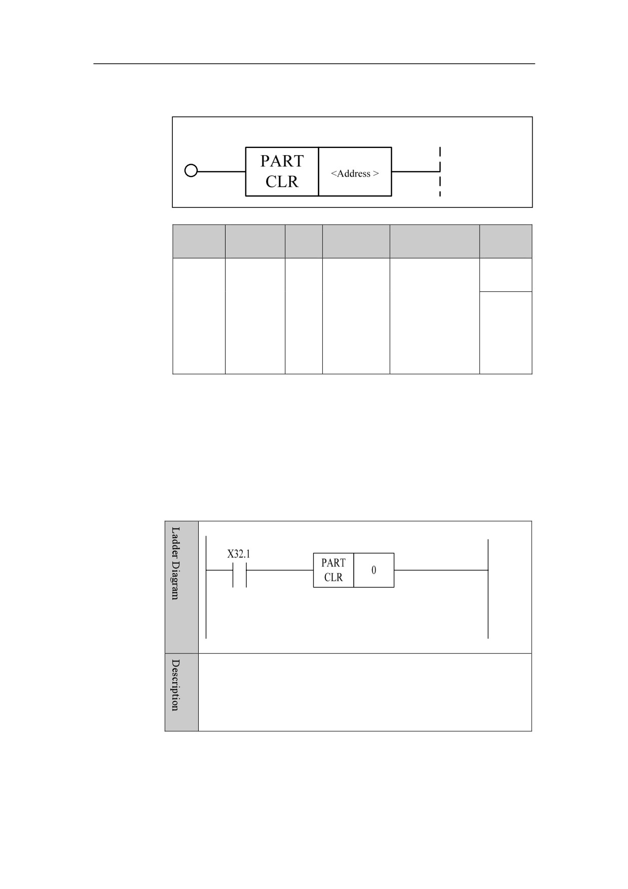
Clear the count of the part.
Parameter
Parameter 1: channel number.
Example
When X32.1 is turned on, the part count in channel 0 is cleared.
138
HNC-8-PLC Component specification
4. Basic function module
139
HNC-8-PLC Component specification
4. Basic function module
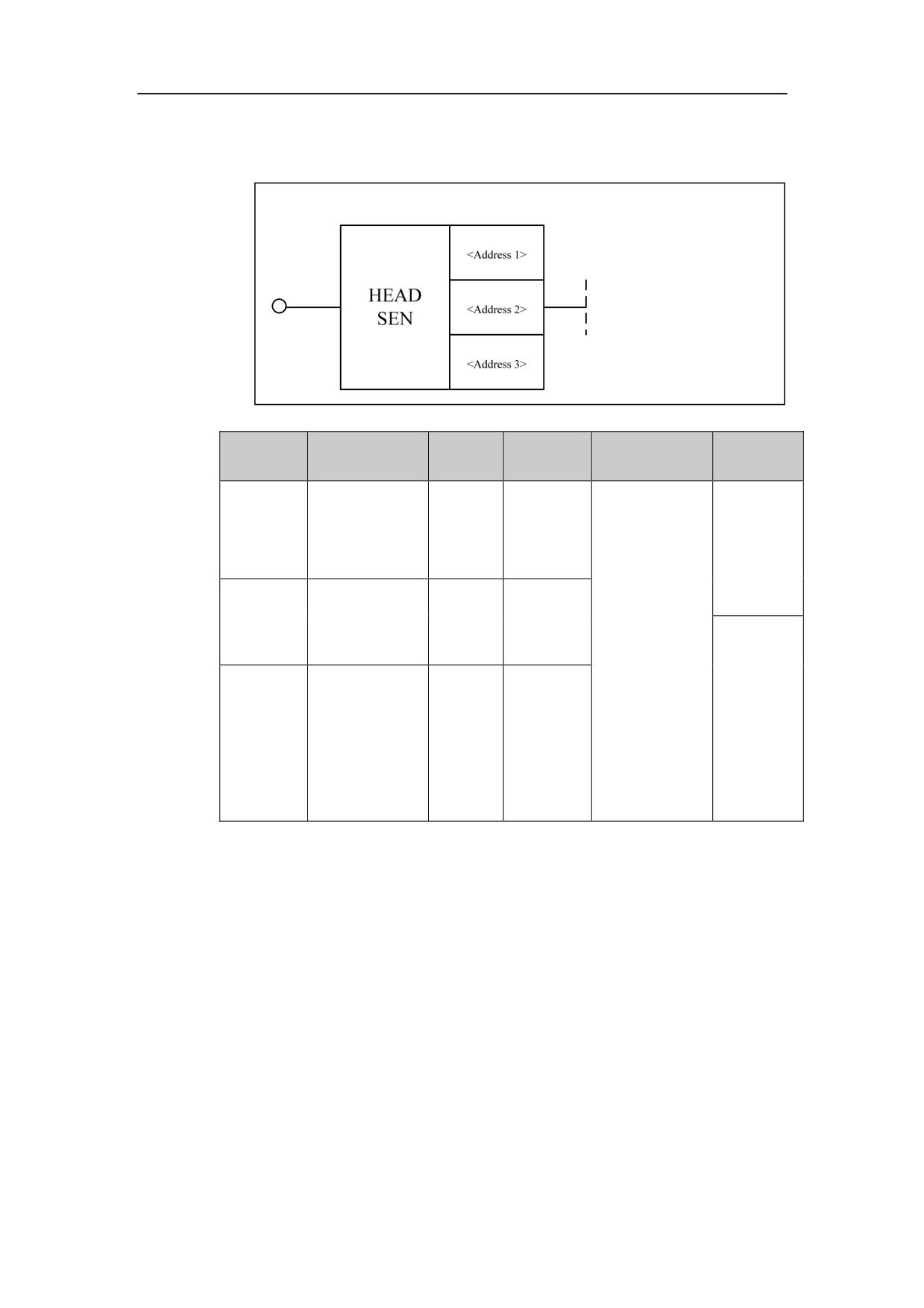
Temperature Collection Module HEADSEN
Format
Parameter
Data
Storage
Parameter
Explanation
Properties
form
type
area
X, Y, F, G,
When Address
<Address
□□□□. □
BOOL
R, W, D, P,
2 is 0, the
Pre ○
1>
T, C, B
temperature
collection
module starts
<Address
□□□□
INT
Constant
to count, and
2>
the
temperature
data in Address
Post×
1 is stored in
<Address
□□□□
INT
Constant
the starting
3>
address given
by Address 3.
Function
Temperature collection module.
Parameter
Parameter 1: total quantity of temperature collection data, can be constant.
Parameter
2: enable switch of temperature collection module,
0 indicates
counting starts, other values indicate the module is not enabled.
Parameter 3: the initial location where the temperature collection data is stored,
and it can be register.
140