HNC-8 Numerical Control System Software. Maual of PLC Programming (V1.24) - page 3
HNC-8-PLC Programming specification
3. Basic component
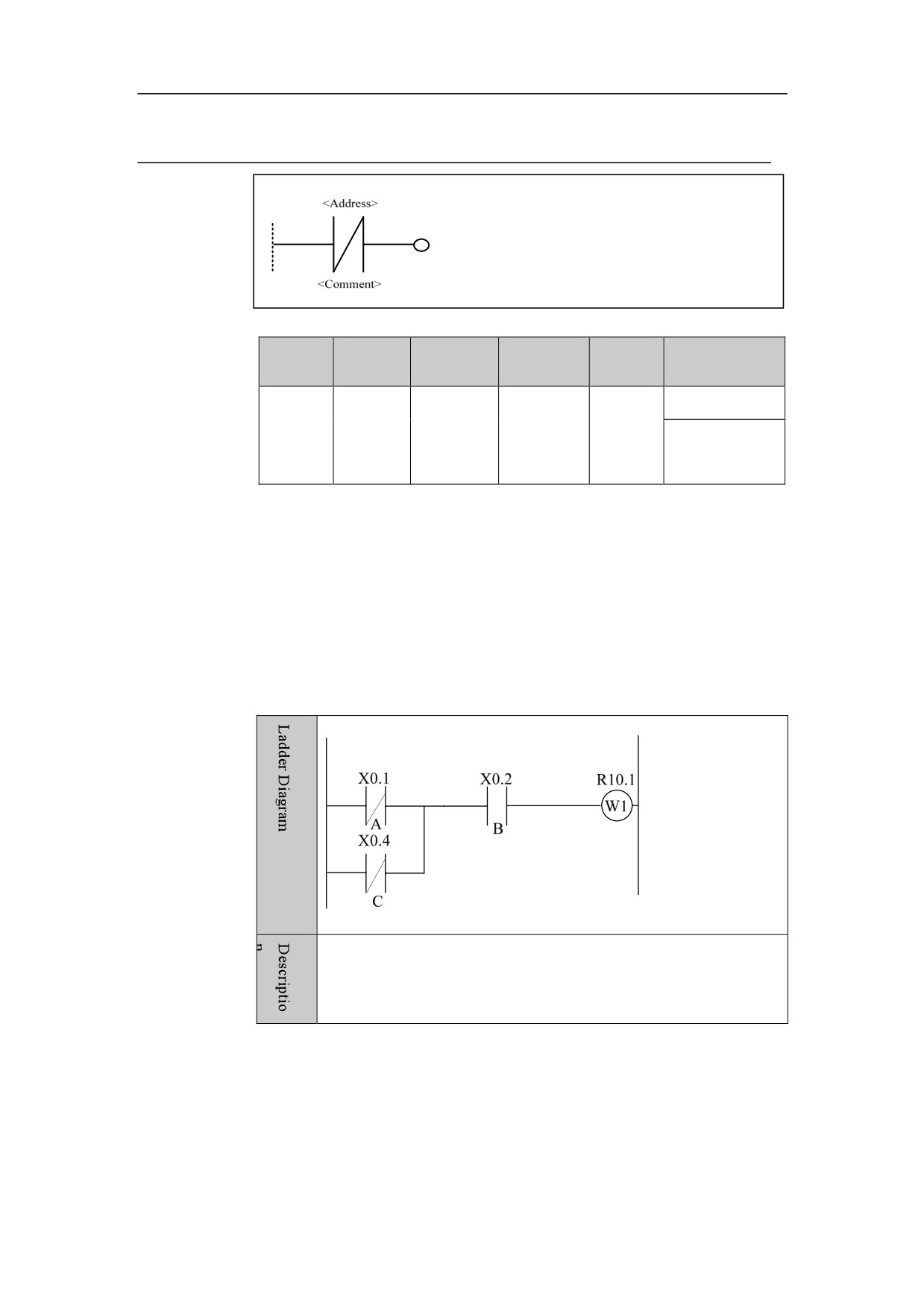
Normal-close Contact
Symbol
Paramet
Paramet
Storage
Explanat
Data type
Properties
er
er form
area
ion
X、Y、F、
Pro
○
Register
<Addres
G、R、W、
□□□□。□
BOOL
bit to be
s>
D、P、T、
Post
√
checked
C、B
Function
When the bit saved in the specified address is “0”, the normal-open contact is
open; If the contact is open, the signal will flow through this contact.
Parameter
Parameter 1: register point parameter, in the form of X0.1.
Example
When signal of X0.1 or X0.4 is “0”, and X0.2 signal is “1”, the
current is conducted, with R10.1 being output.
48
HNC-8-PLC Programming specification
3. Basic component
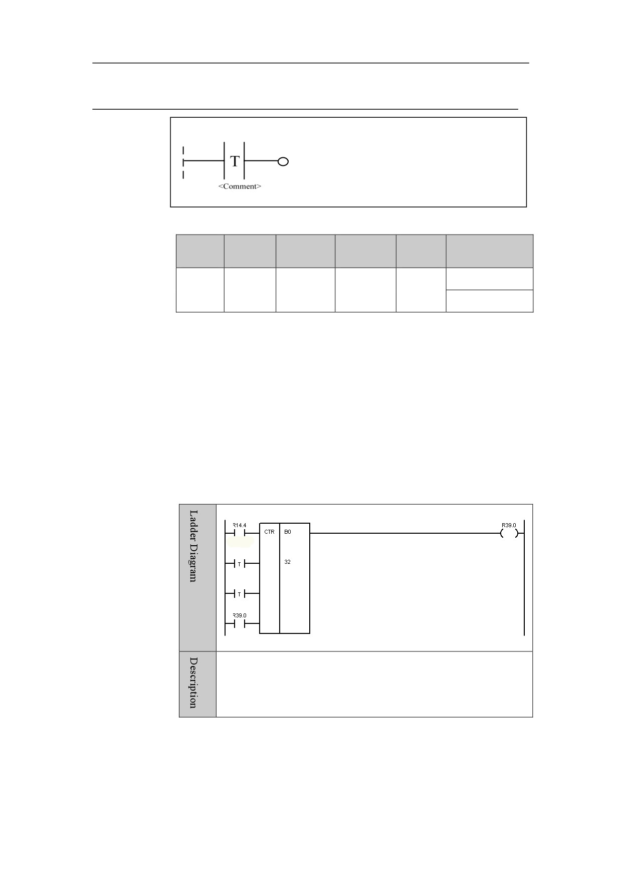
True Contact
Symbol
Parame
Paramet
Storage
Explanat
Data type
Properties
ter
er form
area
ion
Pre
○
None
None
None
None
None
Post
√
Function
When PLC is turned on, the signal on the left of an element can always reach
the right through it. This function is usually used as the switch setting of
function module input, and used for those which need constantly valid input.
Parameter
No parameter.
Example
When the second input of counter uses true contact, the counting
starts with 1 after counter is reset; when the third input uses true
contact, the counter counts in continuous subtraction.
49
HNC-8-PLC Programming specification
3. Basic component
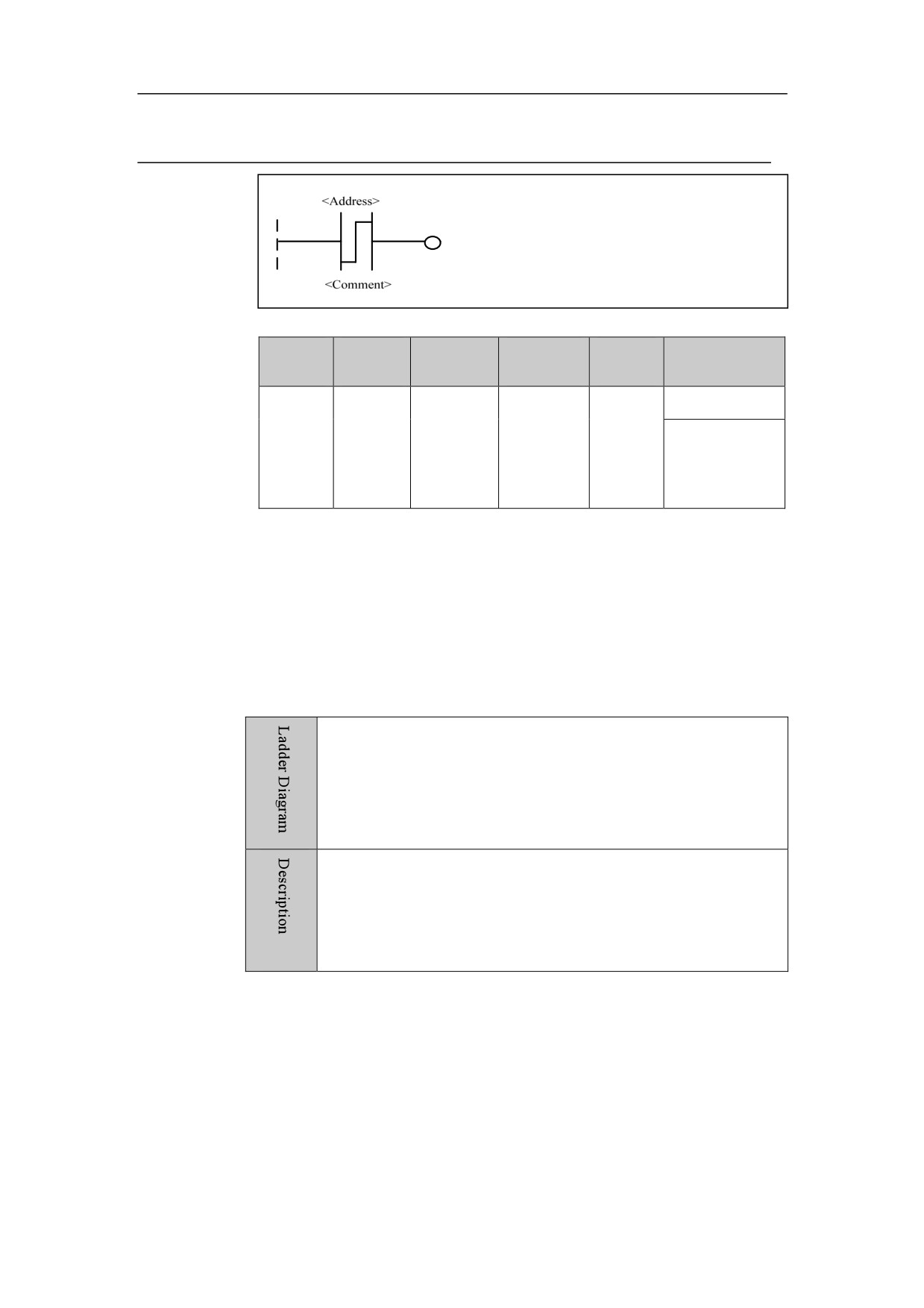
Rising edge of Contact
Symbol
Paramet
Paramet
Storage
Explanat
Data type
Properties
er
er form
area
ion
Contact
Pre
○
X、Y、F、
of rising
<Addres
G、R、W、
□□□□。□
BOOL
edge
s>
D、P、T、
Post
√
detectio
C、B
n
Function
When signal is changed from “0” to “1”, this contact is conducted.
Parameter
Parameter 1: register bit.
Example
See the example for LDP instruction.
50
HNC-8-PLC Programming specification
3. Basic component
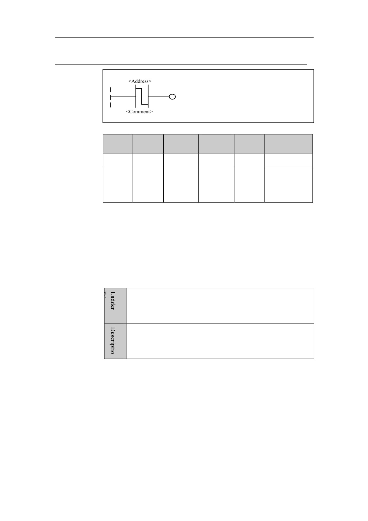
Falling Edge of Contact
Symbol
Paramet
Paramet
Storage
Explanat
Data type
Properties
er
er form
area
ion
Contact
Pre
○
X、Y、F、
of falling
<Addres
G、R、W、
□□□□。□
BOOL
edge
s>
D、P、T、
Post
√
detectio
C、B
n
Function
When signal is changed from “1” to “0”, this contact is conducted.
Parameter
Parameter 1: register bit.
Example
See the example for LDF instruction.
51
HNC-8-PLC Programming specification
3. Basic component
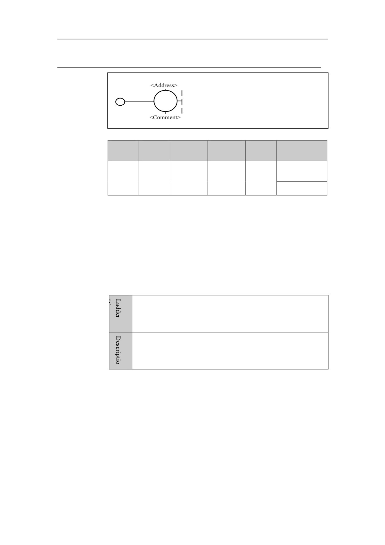
Logic Output
Symbol
Paramet
Paramet
Storage
Explanat
Data type
Properties
er
er form
area
ion
<Addres
BOOL
Y、G、R、
Output
Pre
○
□□□□。□
W、D、B
coil
s>
Post
×
Function
Output result of logical operation to output register.
Parameter
Parameter 1: register bit.
Example
See the example for OUT instruction.
52
HNC-8-PLC Programming specification
3. Basic component
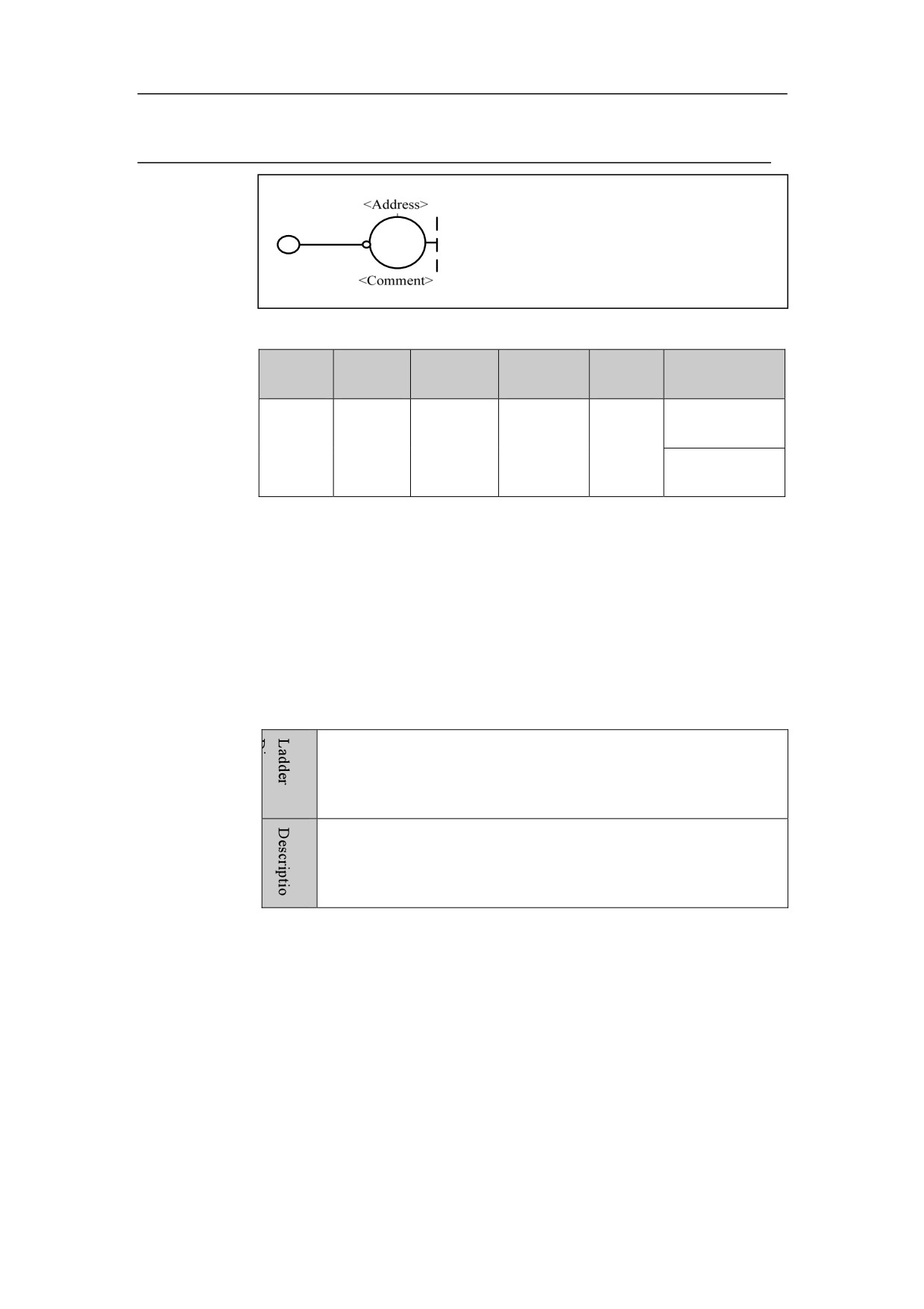
Inverted Logic Output
Symbol
Paramet
Paramet
Storage
Explanat
Data type
Properties
er
er form
area
ion
<Addres
□□□□。□
BOOL
Y、G、R、
Inverted
Pre
○
s>
W、D、B
output
Post
×
coil
Function
Output inverted result of logical operation to output register.
Parameter
Parameter 1: register bit.
Example
See the example for OOUT instruction.
53
HNC-8-PLC Programming specification
3. Basic component
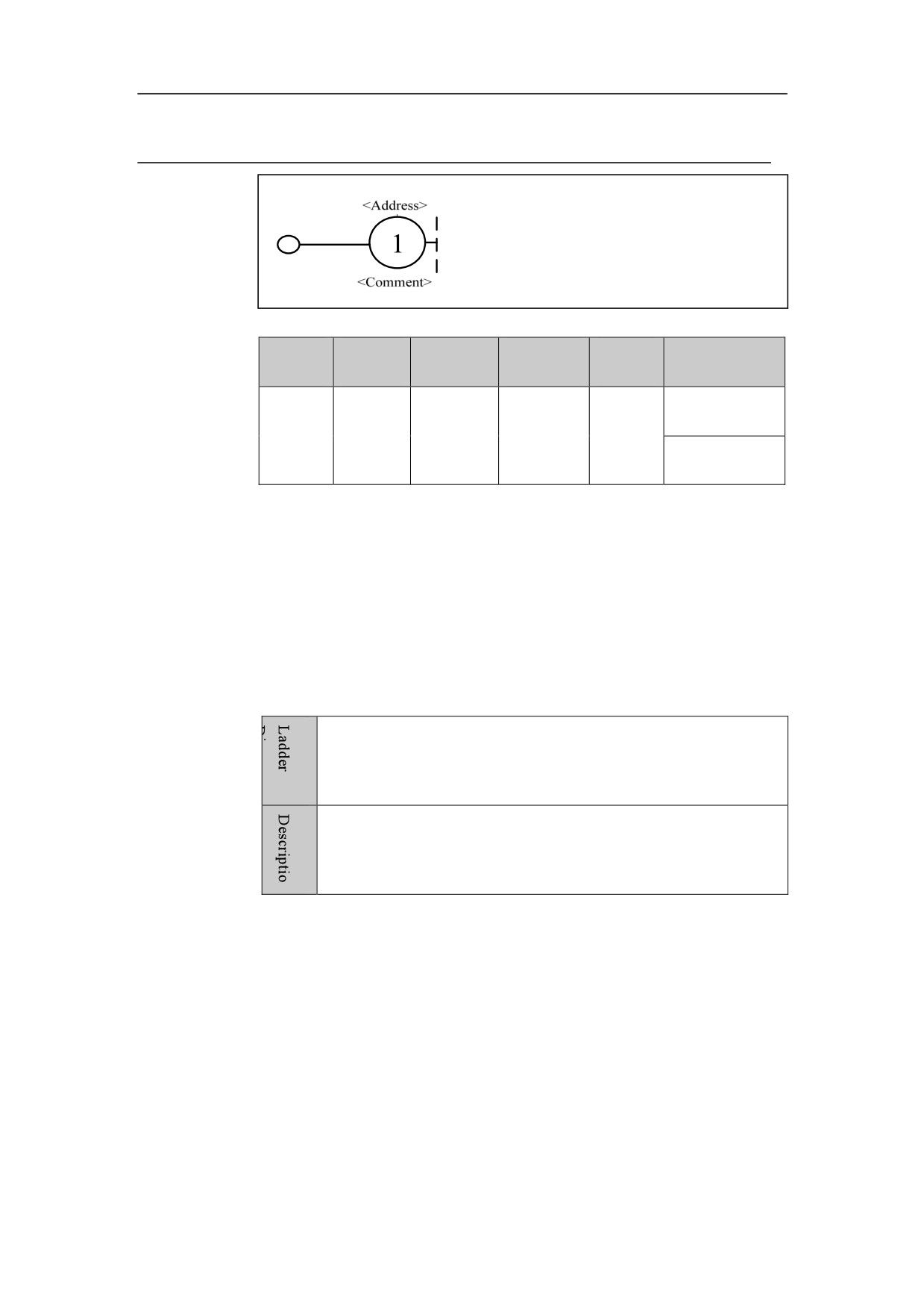
Setting Output
Symbol
Paramet
Paramet
Storage
Explanat
Data type
Properties
er
er form
area
ion
<Addres
□□□□。□
BOOL
Y、G、R、
Setting
Pre
○
s>
W、D、B
output
Post
×
coil
Function
When result of logical operation is “1”, set output coil to output status, until
this coil is reset by other functions.
Parameter
Parameter 1: register bit.
Example
See the example for SET instruction.
54
HNC-8-PLC Programming specification
3. Basic component
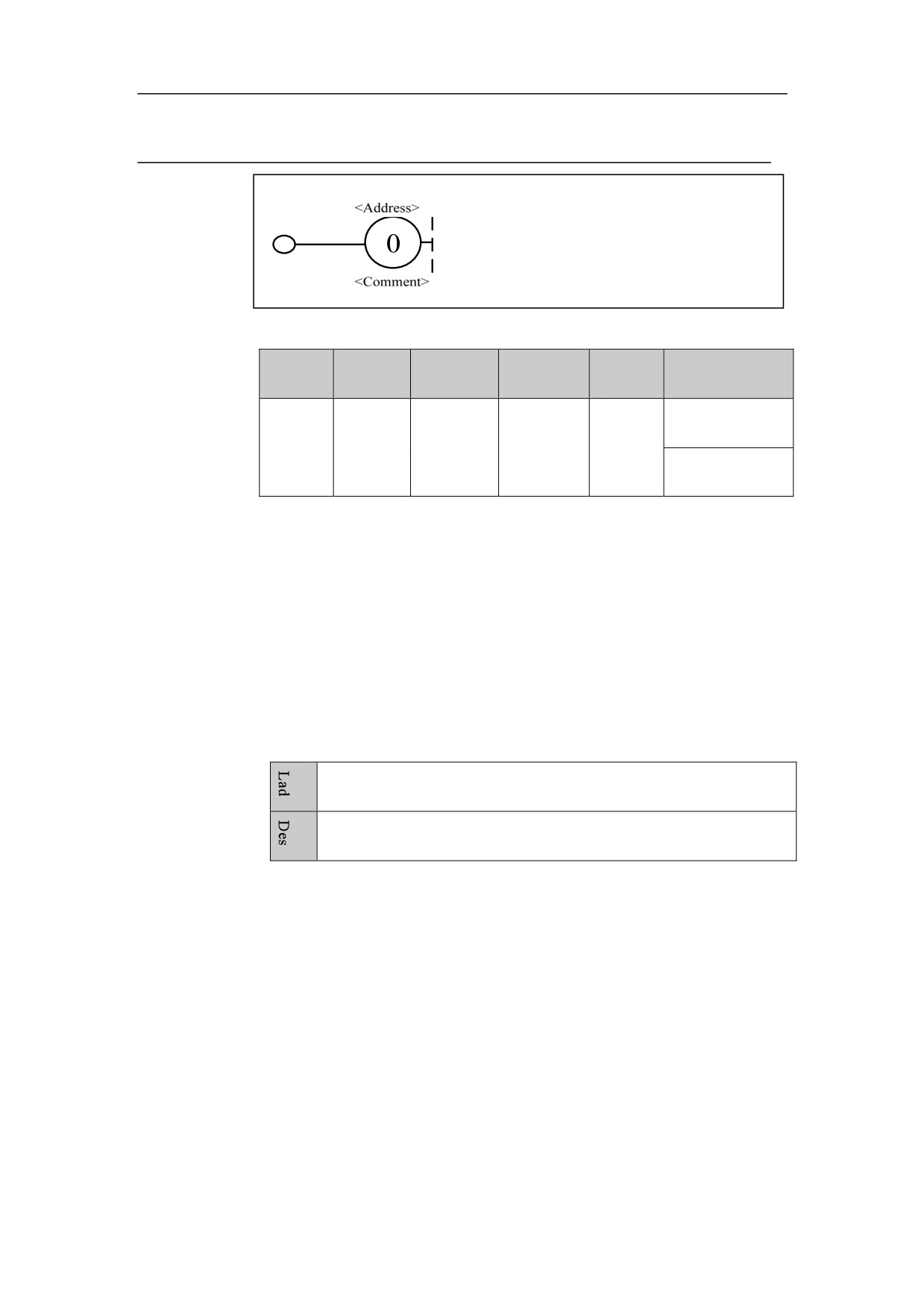
Reset Output
Symbol
Paramet
Paramet
Storage
Explanat
Data type
Properties
er
er form
area
ion
<Addres
□□□□。□
BOOL
Y、G、R、
Reset
Pre
○
s>
W、D、B
output
Post
×
coil
Function
When result of logical operation is “1”, reset output coil, until this coil is set by
other functions.
Parameter
Parameter 1: register bit.
Example
See the example for RST instruction.
55
4. Basic function module
Basic Function Module
This chapter includes:
4.1 Control Instruction
4.2 Mathematical Operation
4.3 Counter
4.4 Timer
4.5 Process Control
4.6 Comparison
4.7 Data Manipulation
56
4. Basic function module
Control Instruction
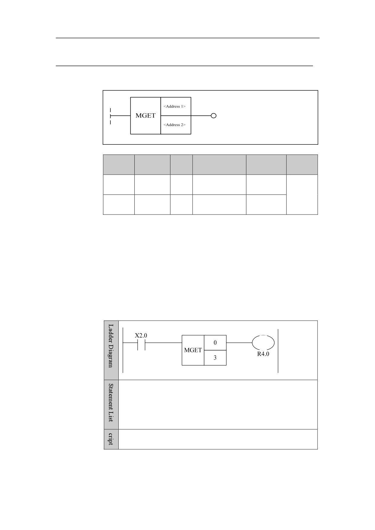
Instructin M Get MGET
Format
Paramet
Parameter
Data
Properti
Storage area
Explanation
er
form
type
es
<Addres
□□□□
INT
Constant
Channel No.
Pre ○
s 1>
<Addres
Post √
□□□□
INT
Constant
M code No.
s 2>
Function
Through the channel selected by parameter 1, parameter 2 selects M code
number which needs to be determined. When this channel gets this M code,
the output is “1”; otherwise, the output is “0”.
Example
LD X2.0
MGET
0
3
WRT R4.0
When channel 0 executes M3, R4.0 is set.
57
4. Basic function module
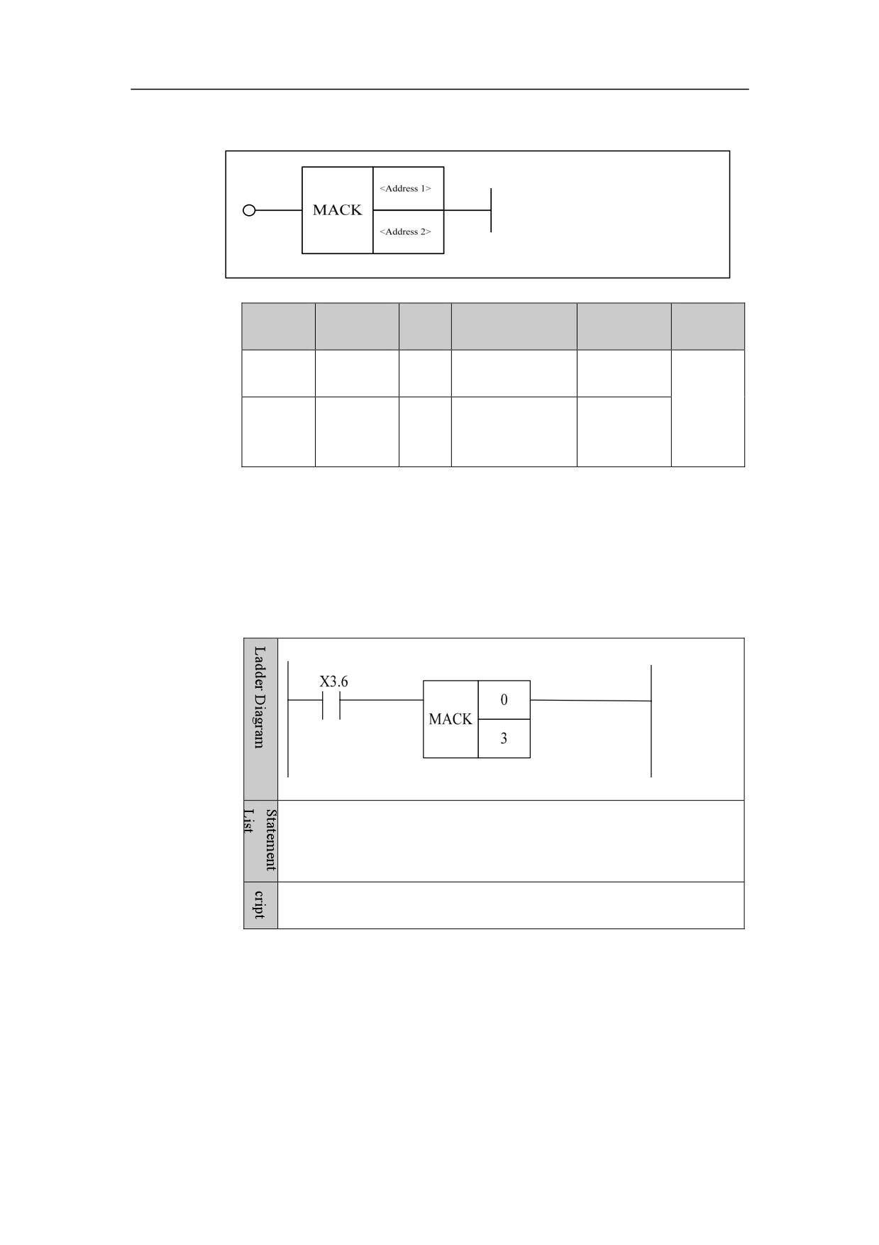
M Instruction Response MACK
Format
Paramet
Parameter
Data
Properti
Storage area
Explanation
er
form
type
es
<Addres
□□□□
INT
Constant
Channel No.
s 1>
Pre ○
<
Post ×
Address
□□□□
INT
Constant
M code No.
2>
Function
When M Code has been implemented in this channel, it is necessary to reply to
M code. After the reply, this M instruction can continue the next instructions.
Example
LD X3.6
MACK
0
3
When X3.6 is effective, M3 in channel 0 is responded.
58
4. Basic function module
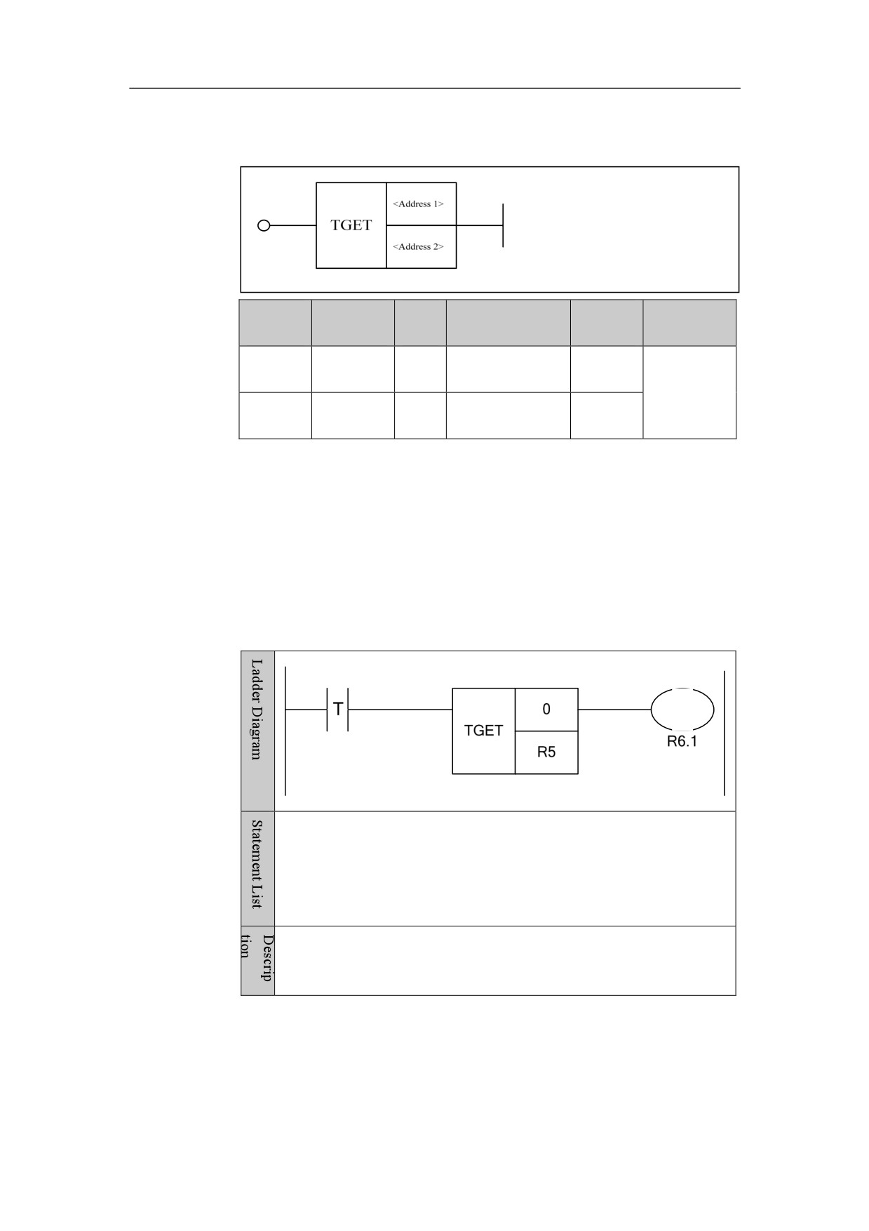
T Instruction Get TGET
Format
Paramet
Parameter
Data
Explanat
Storage area
Properties
er
form
type
ion
<Addres
Channel
Pre
○
□□□□
INT
Constant
s 1>
No.
Post
√
<Addres
INT
Constant, Y, G, R,
T code
□□□□
s 2>
W, D, B
No.
Function
Through the channel selected by parameter 1, parameter 2 is where the gotten
T code is stored in. When this channel gets T code, the output is 1; otherwise,
the output is 0.
Example
LDT
TGET
0 R5
OUT R6.1
When channel 0 executes T instruction, T instruction parameter is sent
to R5 register, and R6.1 is reset.
59
4. Basic function module
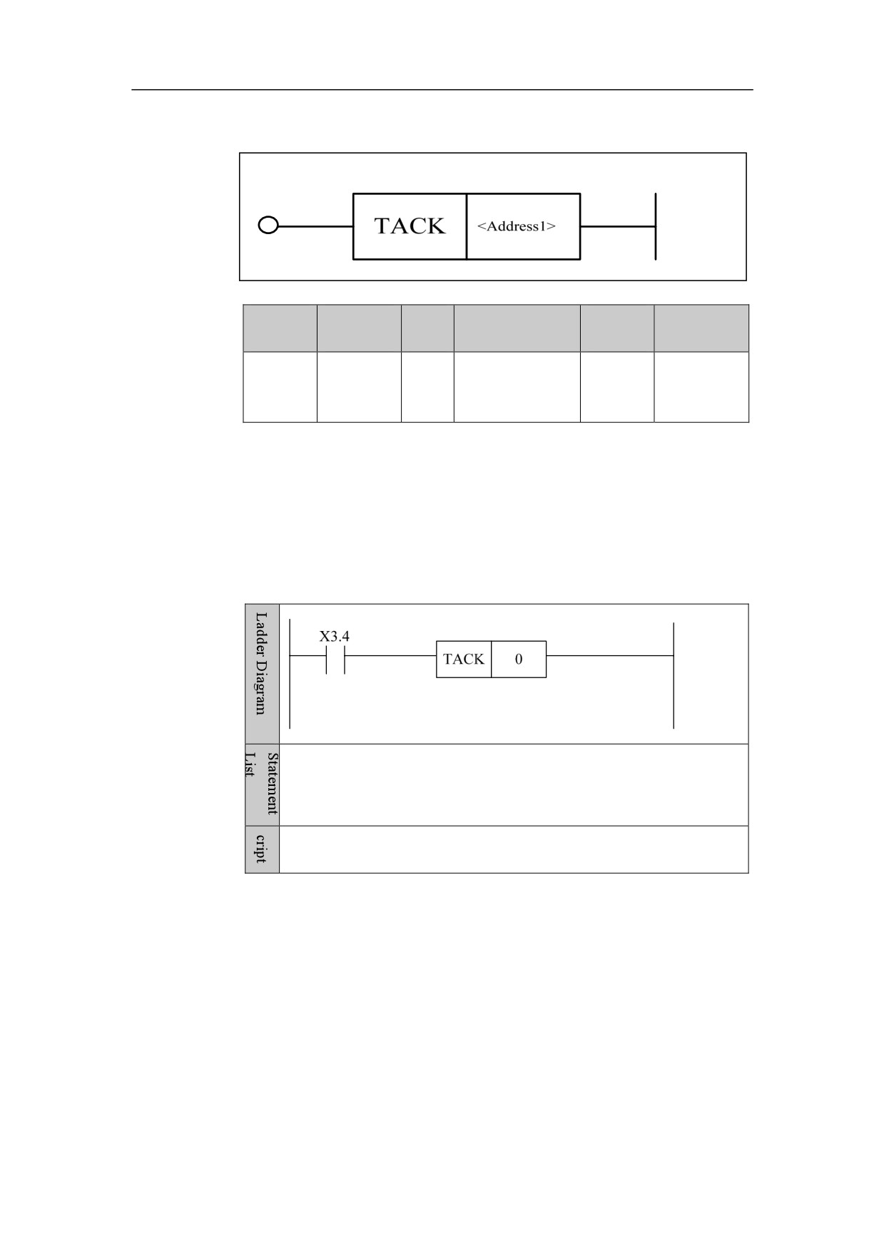
T Instruction Response TACK
Format
Paramet
Parameter
Data
Explanat
Storage area
Properties
er
form
type
ion
Pre
○
<Addres
INT
Constant
Channel
□□□□
Post
×
s 1>
No.
Function
Through the channel selected by parameter 1, set to T code response in this
channel.
Example
LD X3.4
TACK
0
When X3.4 is turned on, T instruction in this channel is replied.
60
4. Basic function module
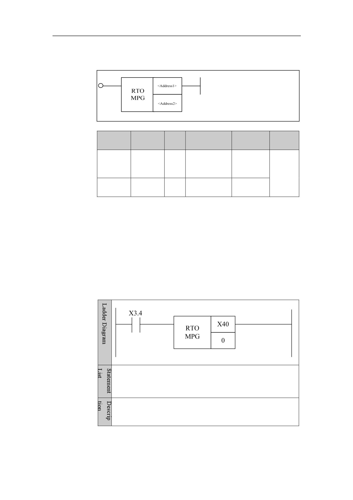
Handwheel Control RTOMPG
Format
Parameter
Data
Properti
Parameter
Storage area
Explanation
form
type
es
Constant, X, Y,
<Address
□□□□
INT
F, G, R, W, D, P,
Pre ○
1>
B
Post ×
<Address
□□□□
INT
Constant
2>
Function
Handwheel control (only for series 8)
Parameter
Parameter 1: the register which the handwheel pulse increment inputs. (The
default register for handwheel of series 8 is X490)
Parameter 2: MPG number, this parameter is for handwheel numbering. When
there are more than one handwheels, they are distinguished by this parameter.
Example
LD X3.4
RTOMPG X40 0
When X3.4 is turned on, enable handwheel control. Handwheel pulse
control register X40 is set into handwheel 0.
61
4. Basic function module
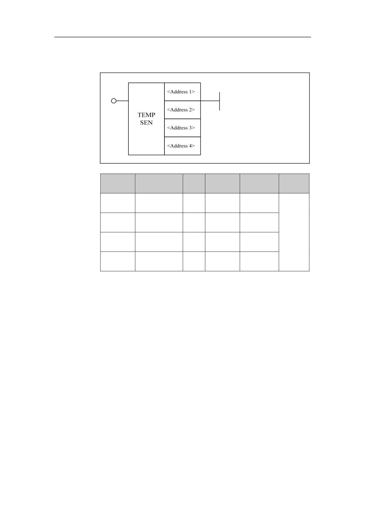
Thermal Error Compensation Module TEMPSEN
Format
Parameter
Data
Storage
Properti
Parameter
Explanation
form
type
area
es
<Address
□□□□
INT
Constant
1>
< Address
□□□□. □
BOOL
X
Pre ○
2>
< Address
Post ×
□□□□
INT
Constant
3>
< Address
□□□□. □
BOOL
P
4>
Function
Analog signal of temperature sensor is converted to digital signal by AD of IO module, and is
input to a positon (group number) of X register which is determined by device parameter of IO
module.
Parameter
Parameter 1: number of temperature sensor (number of temperature register). HNC-8 NC system
is limited to input of
20 temperature acquisition signals. Therefore, the range of values for
temperature sensor number is zero to nineteen.
Parameter 2: group number of X register corresponding to the digital signal of temperature
acquisition.
Parameter 3: thermocouple grid type (its default value is 0. 1: the corresponding model is built to
calculate temperature, by the user parameter specified by “parameter 4” which includes the lowest
and highest (the temperature corresponding to the voltage of 6.7 V) temperatures; 2: temperature
62
4. Basic function module
sensor of PT100 is supported, and thermocouple grid of HIO-1075 is connected; 3: temperature
sensor of KTY84-300 is supported, and thermocouple grid of HIO-1076 is connected; 4: the
relationship between the measured temperature and the resistance calculated by the entered value
of DA is linear. The corresponding model is built to calculate temperature, by the user parameter
(P parameter) specified by “parameter 4” which includes the lowest and highest temperatures, as
well as minimum and maximum resistances (unit: 0.01ȍ).
Note: The thermocouple grid type of 2 and 3 are standard configurations, where the corresponding
bus thermocouple grid can be connected, there are models of corresponding temperature in system,
and the value of P parameter doesn’t need to be set.
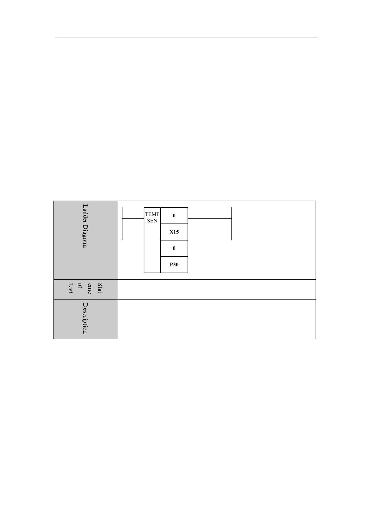
Parameter 4: set the range of acquisition temperature for temperature sensor by user parameter (P
parameter). As shown in the figure below, P30 specifies the acquisition for the lowest
temperatures, and P31 specifies the acquisition for the highest temperatures (the temperature
corresponding to the voltage of 6.7 V, unit: degree). If the thermocouple grid type is 2 or 3, set
value of P parameter will not be read.
TEMPSEN
0 X15
0 P30
The temperatures which have been gathered by No. 0 temperature
sensor, is put into X15 register. P30 specifies the lowest acquisition
temperatures.
Example
63
4. Basic function module
Mathematical Operation
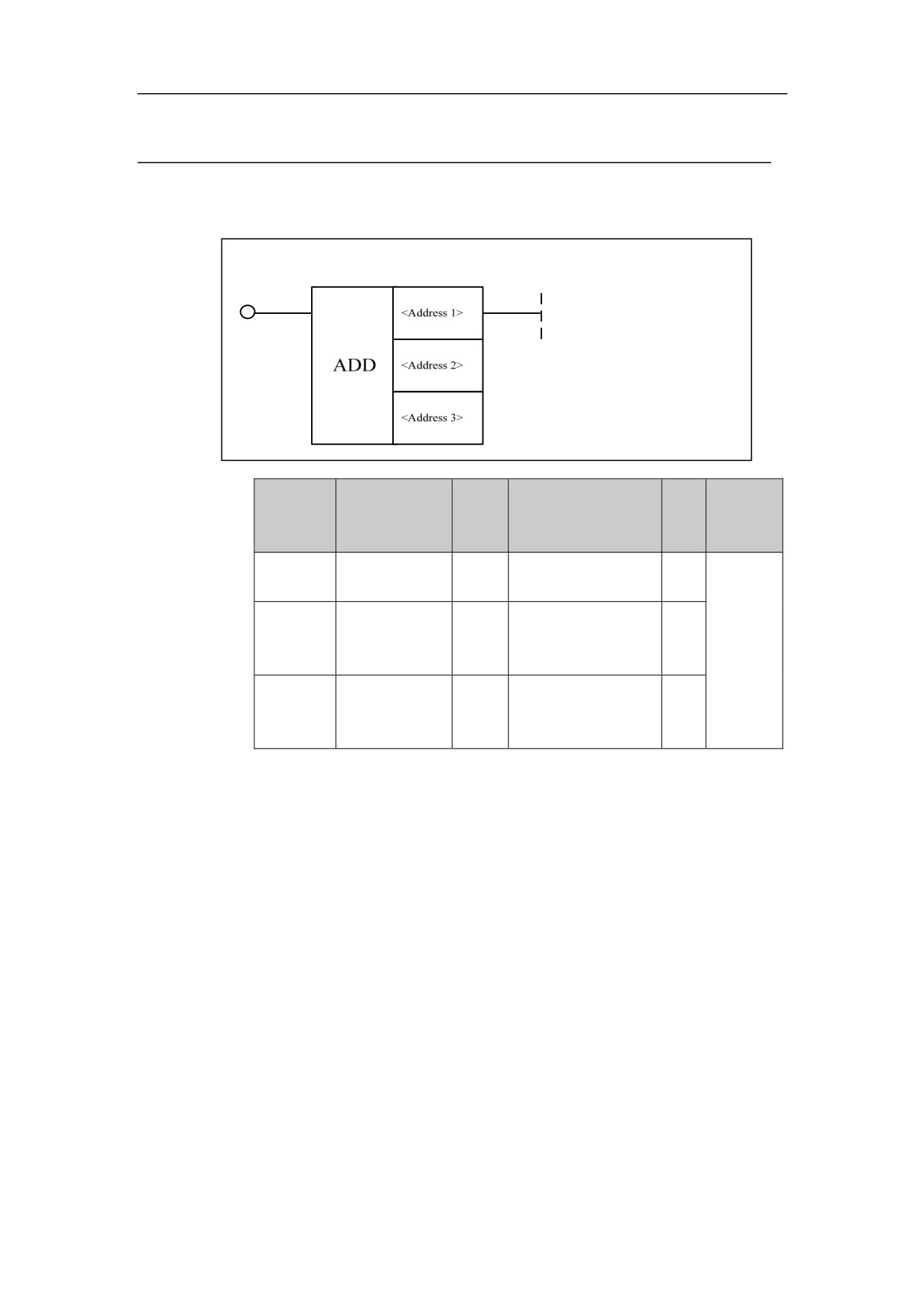
Addition ADD
Format
Expl
Paramete
Parameter
Data
Properti
Storage area
ana
r
form
type
es
tion
<Address
INT
Constant, X, Y, F, G,
□□□□
1>
R, W, D, P, B
<
INT
Constant, X, Y, F, G,
Address
□□□□
R, W, D, P, B
Pre √
2>
Post ○
<
Address
□□□□
INT
Y, G, R, W, D, B
3>
Function
Perform addition operation.
Parameter
Parameter 1: augend
Parameter 2: addend
Parameter 3: operation result output address.
64
4. Basic function module
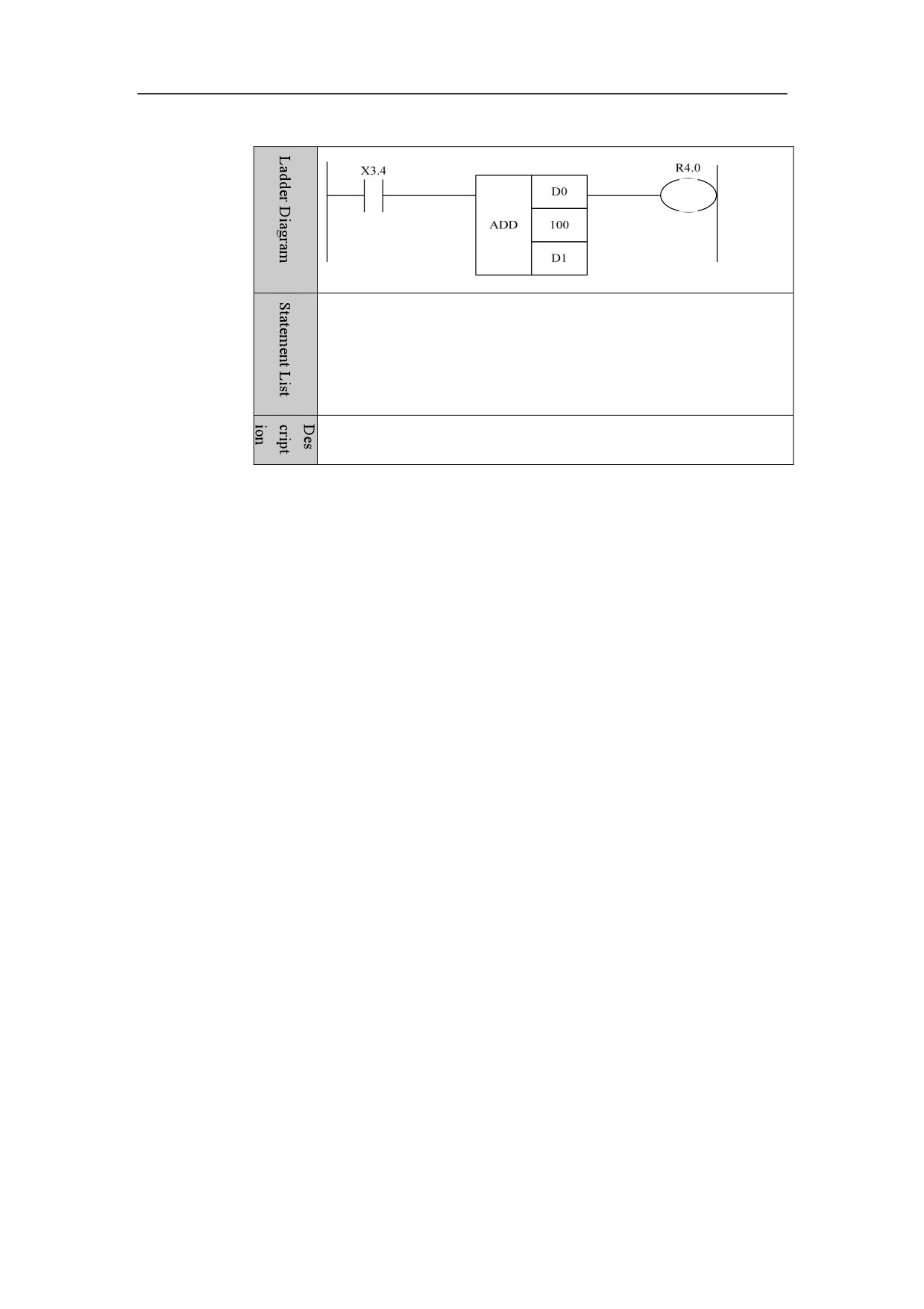
Example
LD X3.4
ADD D0
100 D1
OUT R4.0
When X3.4 is turned on, D1=D0+100 is implemented.
65
4. Basic function module
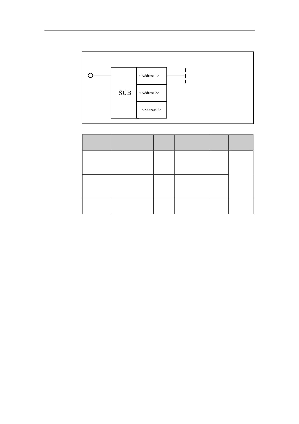
Subtraction SUB
Format
Data
Expla
Properti
Parameter
Parameter form
Storage area
type
nation
es
INT
Constant, X、
< Address
□□□□
Y, F, G, R, W,
1>
D, P, B
INT
Constant, X,
Pre √
< Address
□□□□
Y, F, G, R, W,
Post ○
2>
D, P, B
< Address
Y, G, R, W, D,
□□□□
INT
3>
B
Function
Perform subtraction operation.
Parameter
Parameter 1: minuend
Parameter 2: subtrahend
Parameter 3: operation result output address.
66
4. Basic function module
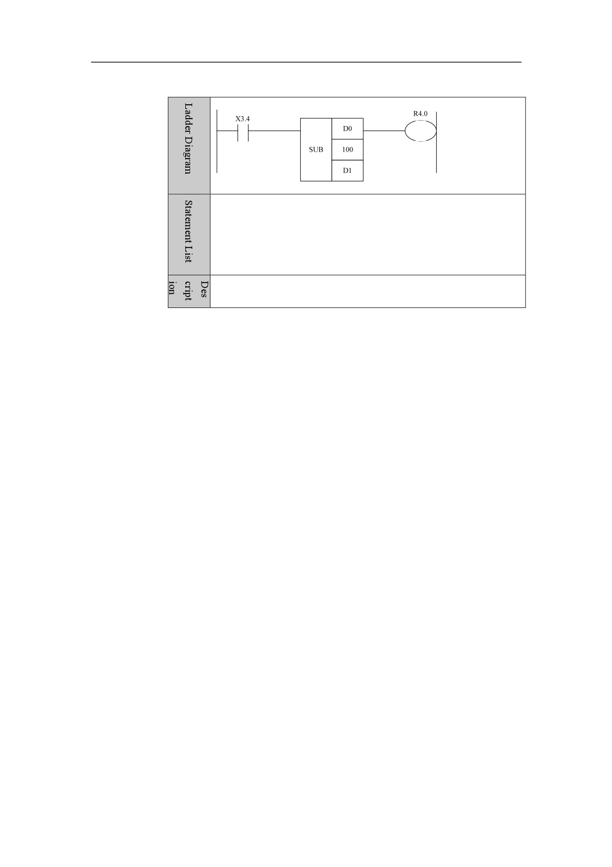
Example
LD X3.4
SUB D0
100 D1
OUT R4.0
When X3.4 is turned on, D1=D0-100 is implemented.
67
4. Basic function module
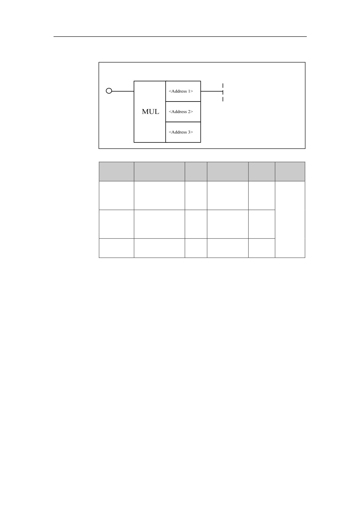
Multiplication MUL
Format
Data
Explana
Properti
Parameter
Parameter form
Storage area
type
tion
es
INT
Constant, X,
<Address
□□□□
Y, F, G, R, W,
1>
D, P, B
INT
Constant, X,
Pre √
<Address
□□□□
Y, F, G, R, W,
Post ○
2>
D, P, B
<Address
Y, G, R, W, D,
□□□□
INT
3>
B
Function
Perform multiplication operation.
Parameter
Parameter 1: multiplicand
Parameter 2: multiplier
Parameter 3: operation result output address.
68
4. Basic function module
Example
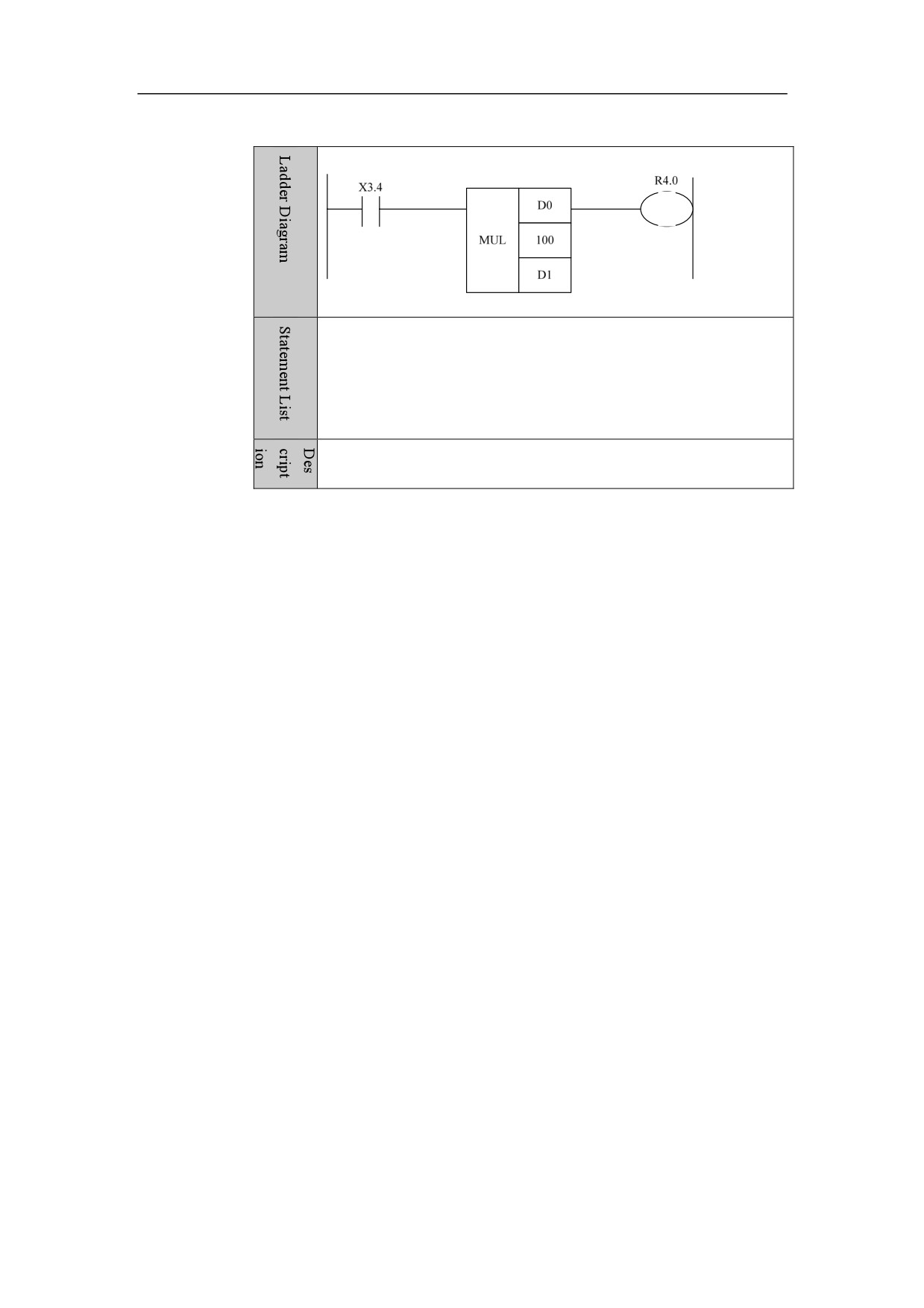
LD X3.4
MUL D0
100 D1
OUT R4.0
D1=D0*100 When X3.4 is turned on, D1=D0*100 is implemented.
69
4. Basic function module
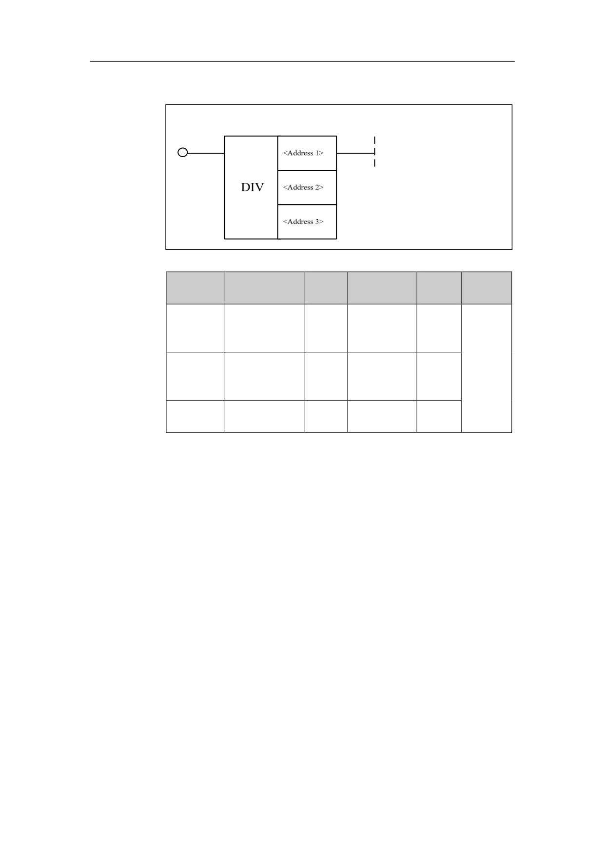
Division DIV
Format
Parameter
Data
Explana
Properti
Parameter
Storage area
form
type
tion
es
INT
Constant, X,
<Address
□□□□
Y, F, G, R, W,
1>
D, P, B
INT
Constant, X,
Pre √
<Address
□□□□
Y, F, G, R, W,
Post ○
2>
D, P, B
<Address
Y, G, R, W, D,
□□□□
INT
3>
B
Function
Perform division operation.
Parameter
Parameter 1: dividend
Parameter 2: divisor
Parameter 3: operation result output address.
70
4. Basic function module
Example
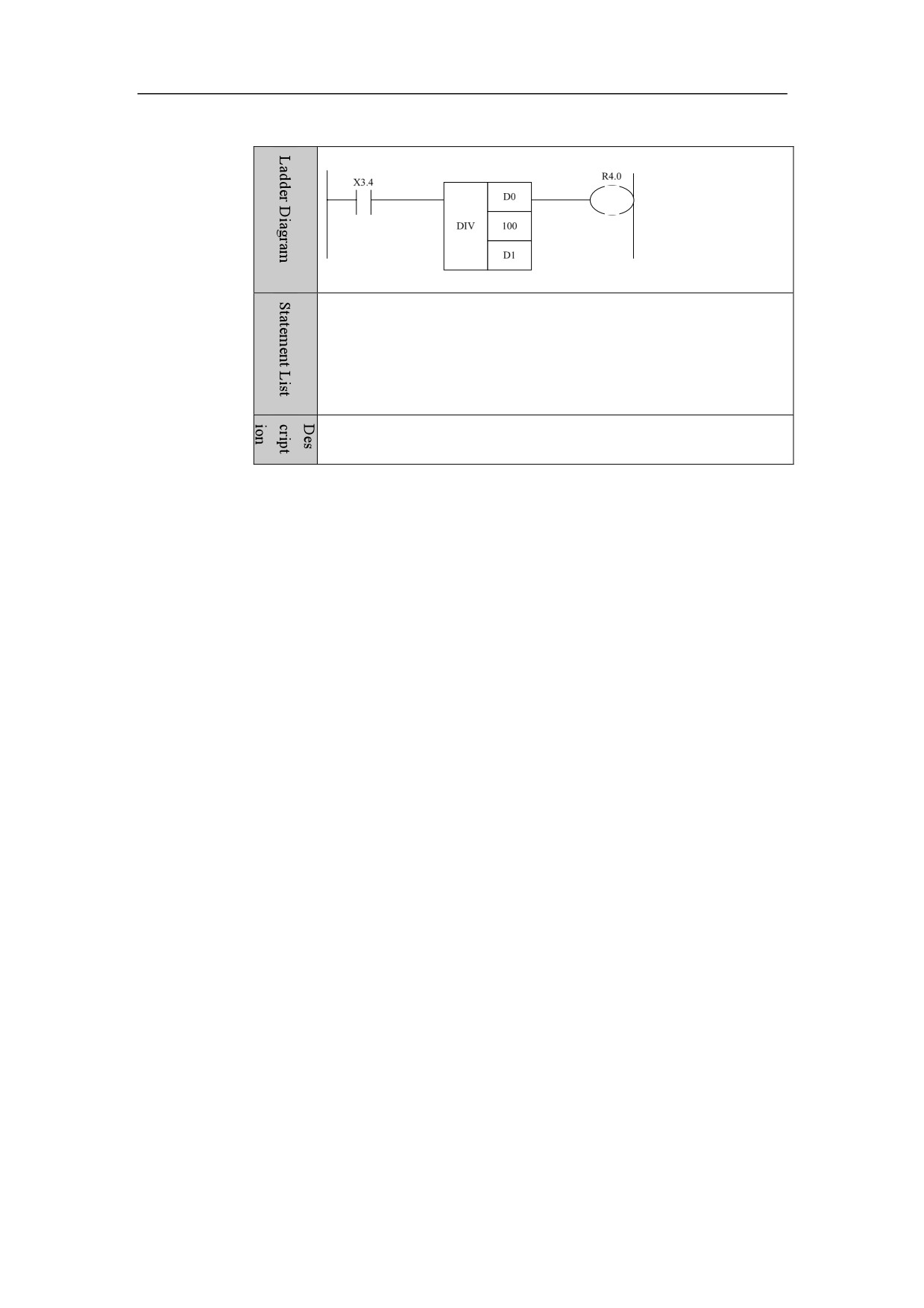
LD X3.4
DIV D0
100 D1
OUT R4.0
When X3.4 is turned on, D1=D0/100 is implemented.
71
4. Basic function module
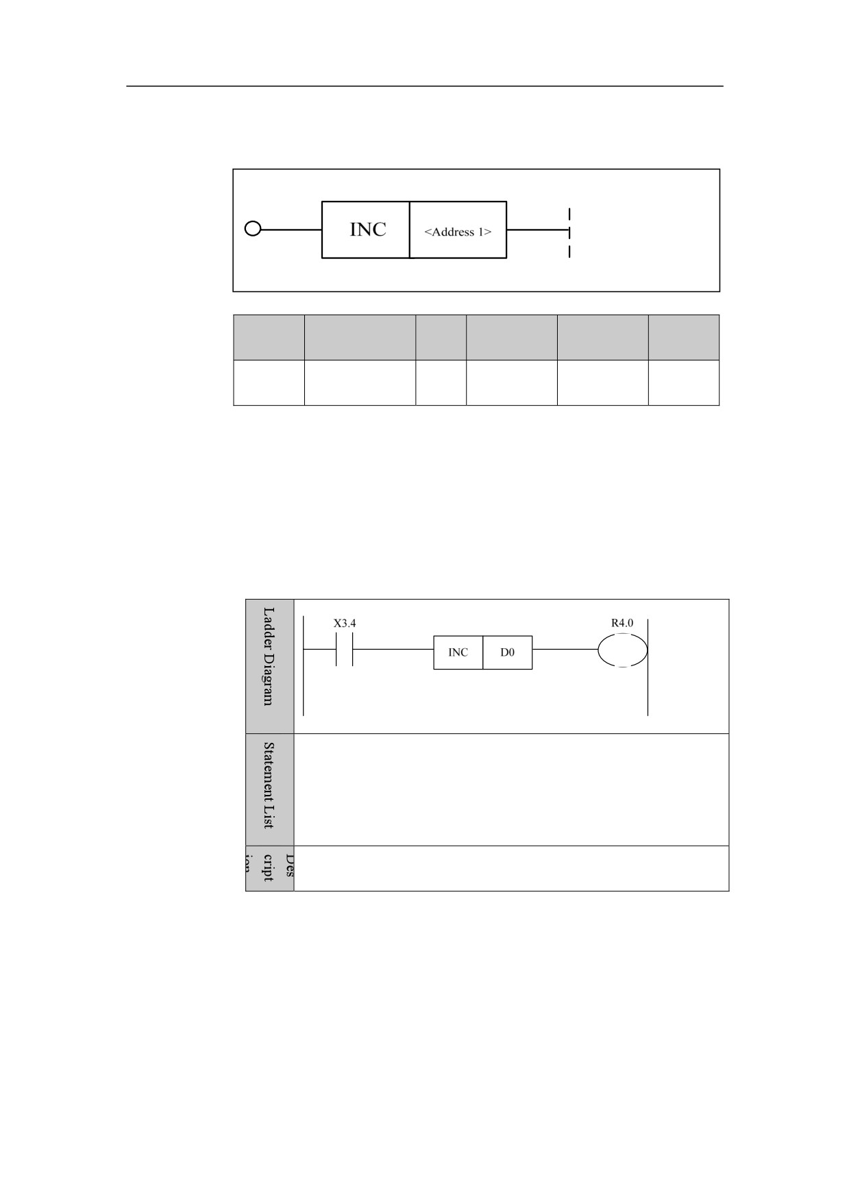
Increase One INC
Format
Paramet
Parameter
Data
Storage
Properti
Explanation
er
form
type
area
es
<Addres
INT
Y, G, R, W,
Pre √
□□□□
s 1>
D, B
Post ○
Function
Perform plus-one operation.
Parameter
Parameter 1: operand.
Example
LD X3.4
INC D0
OUT R4.0
When X3.4 is turned on, D0=D0+1 is implemented.
72

4. Basic function module
Decrease One DEC
Format
Paramet
Parameter
Data
Storage
Properti
Explanation
er
form
type
area
es
<Addres
INT
Y, G, R, W,
Pre √
□□□□
s 1>
D, B
Post ○
Function
Perform minus-one operation.
Parameter
Parameter 1: operand.
Example
LD X3.4
DEC D0
OUT R4.0
When X3.4 is turned on, D0=D0-1 is implemented.
73
4. Basic function module
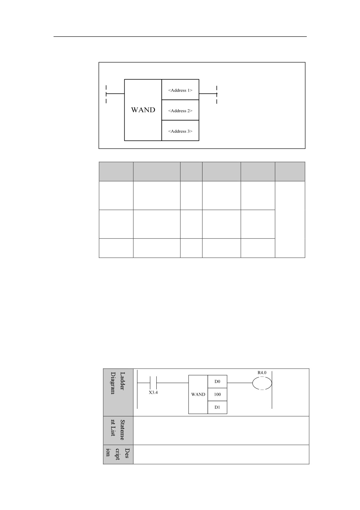
Logic AND WAND
Format
Parameter
Data
Storage
Explanatio
Properti
Parameter
form
type
area
n
es
INT
Constant, X,
<Address
□□□□
Y, F, G, R,
1>
W, D, P, B
INT
Constant, X,
Pre √
<Address
□□□□
Y, F, G, R,
Post ○
2>
W, D, P, B
<Address
Y, G, R, W,
□□□□
INT
3>
D, B
Function
Perform logic AND.
Parameter
Parameter 1: the number being operated.
Parameter 2: operand.
Parameter 3: operation result output address.
Example
LD X3.4
WAND D0
100 D1
OUT R4.0
When X3.4 is turned on, D0=D0&100 is implemented.
74
4. Basic function module
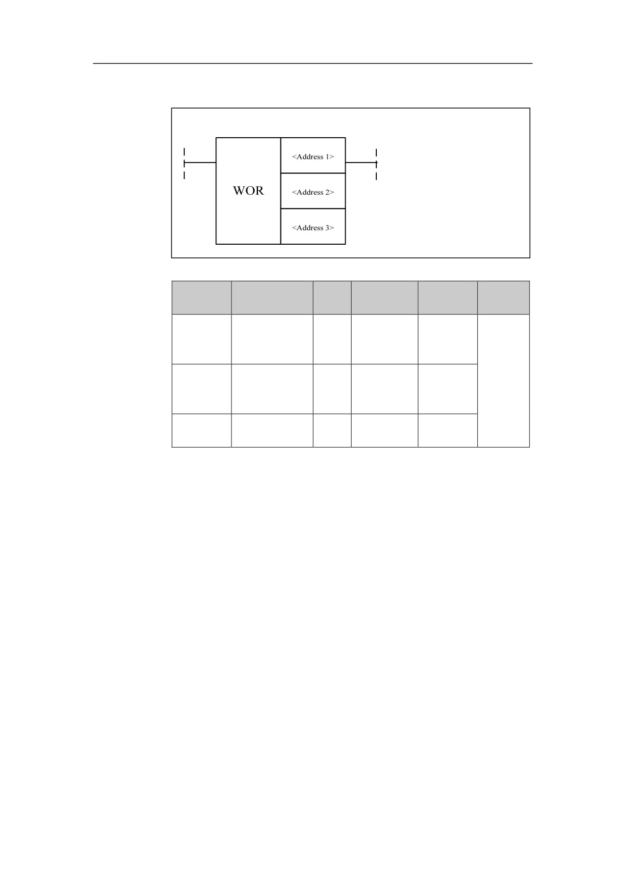
Logic OR WOR
Format
Parameter
Data
Storage
Explanatio
Properti
Parameter
form
type
area
n
es
INT
Constant, X,
<Address
□□□□
Y, F, G, R,
1>
W, D, P, B
INT
Constant, X,
Pre √
<Address
□□□□
Y, F, G, R,
Post ○
2>
W, D, P, B
<Address
Y, G, R, W,
□□□□
INT
3>
D, B
Function
Perform logic OR
Function
Parameter 1: the number being operated.
Parameter 2: operand.
Parameter 3: operation result output address.
75
4. Basic function module
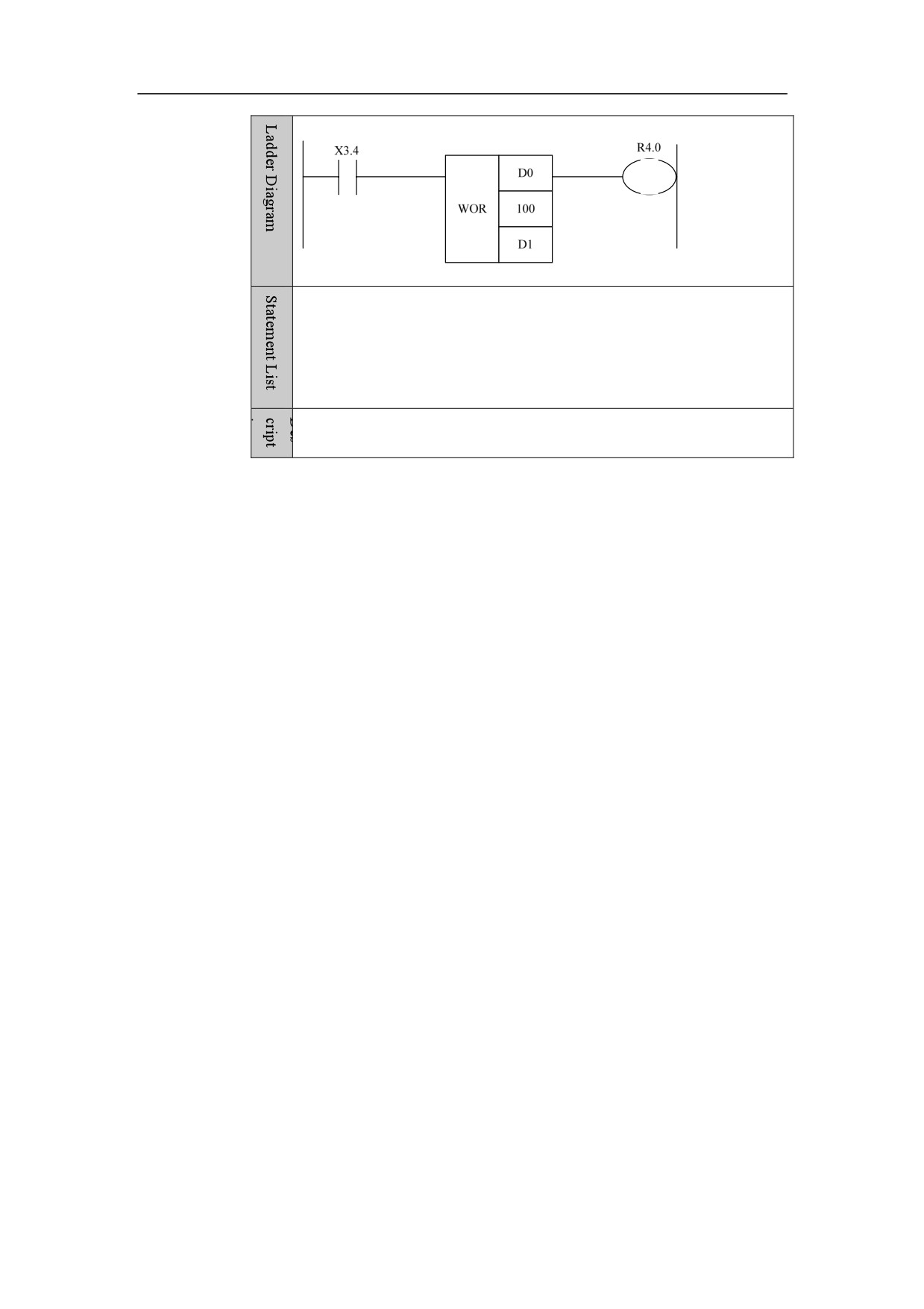
Example
LD X3.4
WOR D0
100 D1
OUT R4.0
When X3.4 is turned on, D0=D0|100 is implemented.
76
4. Basic function module
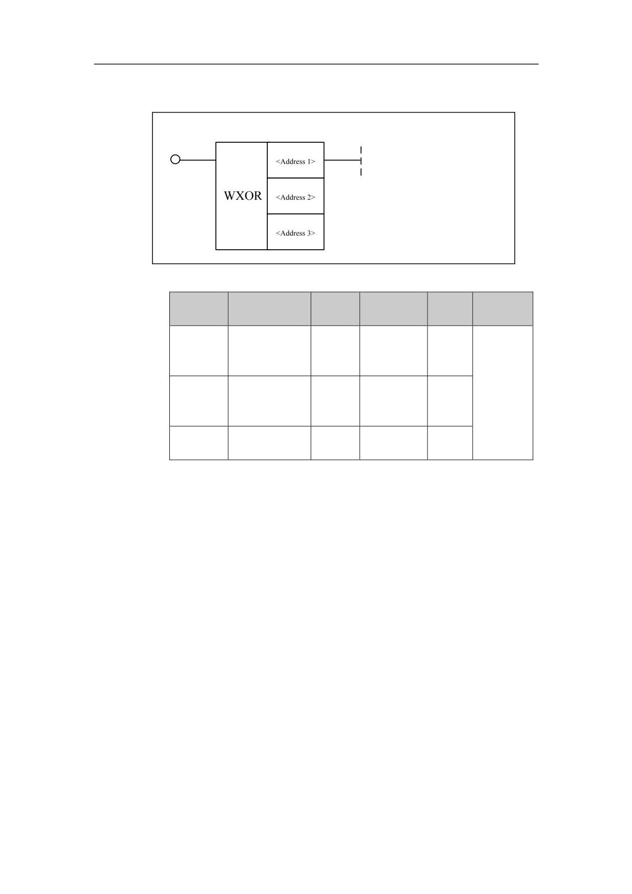
Logic XOR WXOR
Format
Paramete
Parameter
Data
Storage
Explan
Properties
r
form
type
area
ation
INT
Constant, X,
<Address
□□□□
Y, F, G, R,
1>
W, D, P, B
INT
Constant, X,
Pre √
<Address
□□□□
Y, F, G, R,
Post ○
2>
W, D, P, B
<Address
Y, G, R, W,
□□□□
INT
3>
D, B
Function
Perform logic XOR.
Parameter
Parameter 1: the number being operated.
Parameter 2: operand
Parameter 3: operation result output address.
77
4. Basic function module
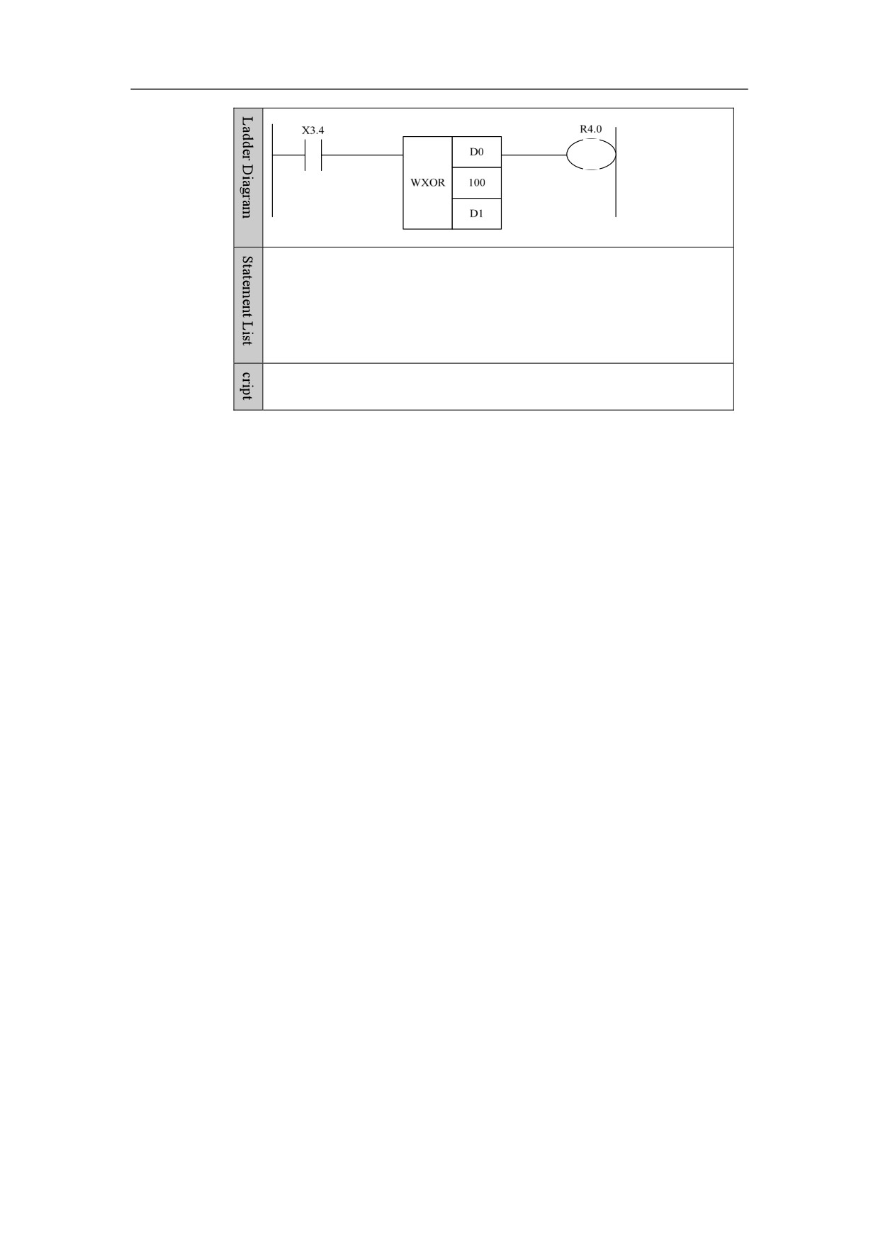
Example
LD X3.4
WXOR D0
100 D1
OUT R4.0
When X3.4 is turned on, D0=D0^100 is implemented.
78