HNC-8 Numerical Control System Software. Maual of PLC Programming (V1.24) - page 2
HNC-8-PLC Programming specification
2. Basic instruction
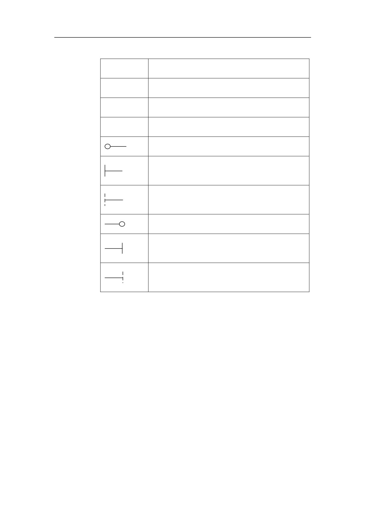
Graphics
Meaning
○
Can be used or not
√
Must be used
×
Cannot be used
Can use pre component or not
Must use pre component
Cannot use pre component
Can use post component or not
Must use post component
Cannot use post component
17

HNC-8-PLC Programming specification
2. Basic instruction
Detailed basic instructions are listed below:
No.
Instruc
Function
tion
1
LD
Read in specified element signal status
2
LDI
Read in inverted status of specified element signal
3
LDT
Read in ture element signal status
4
OUT
Output result of logical operation to specified address
5
OOUT
Output inver result of logical operation to specified address
6
SET
After Logic OR the calculation result to signal in specified
address, return the result to this address.
7
RST
After Logic AND the inverted calculation result to signal in
specified address, return the result to this address.
8
AND
Logic AND
9
ANI
Logic AND the inverted specified signal
10
OR
Ligic OR
11
ORI
Logic OR the inverted specified signal
12
LDP
Read in rising edge of signal
13
LDF
Read in falling edge of signal
14
ANDP
Logic AND rising edge of specified signal
15
ANDF
Logic AND falling edge of specified signal
16
ORP
Ligic OR rising edge of specified signal
17
ORF
Ligic OR falling edge of specified signal
18
ORB
Block logic OR
19
ANB
Block logic AND
20
MPS
Node result push
21
MRD
Reading node result
22
MPP
Node result pull
18
HNC-8-PLC Programming specification
2. Basic instruction
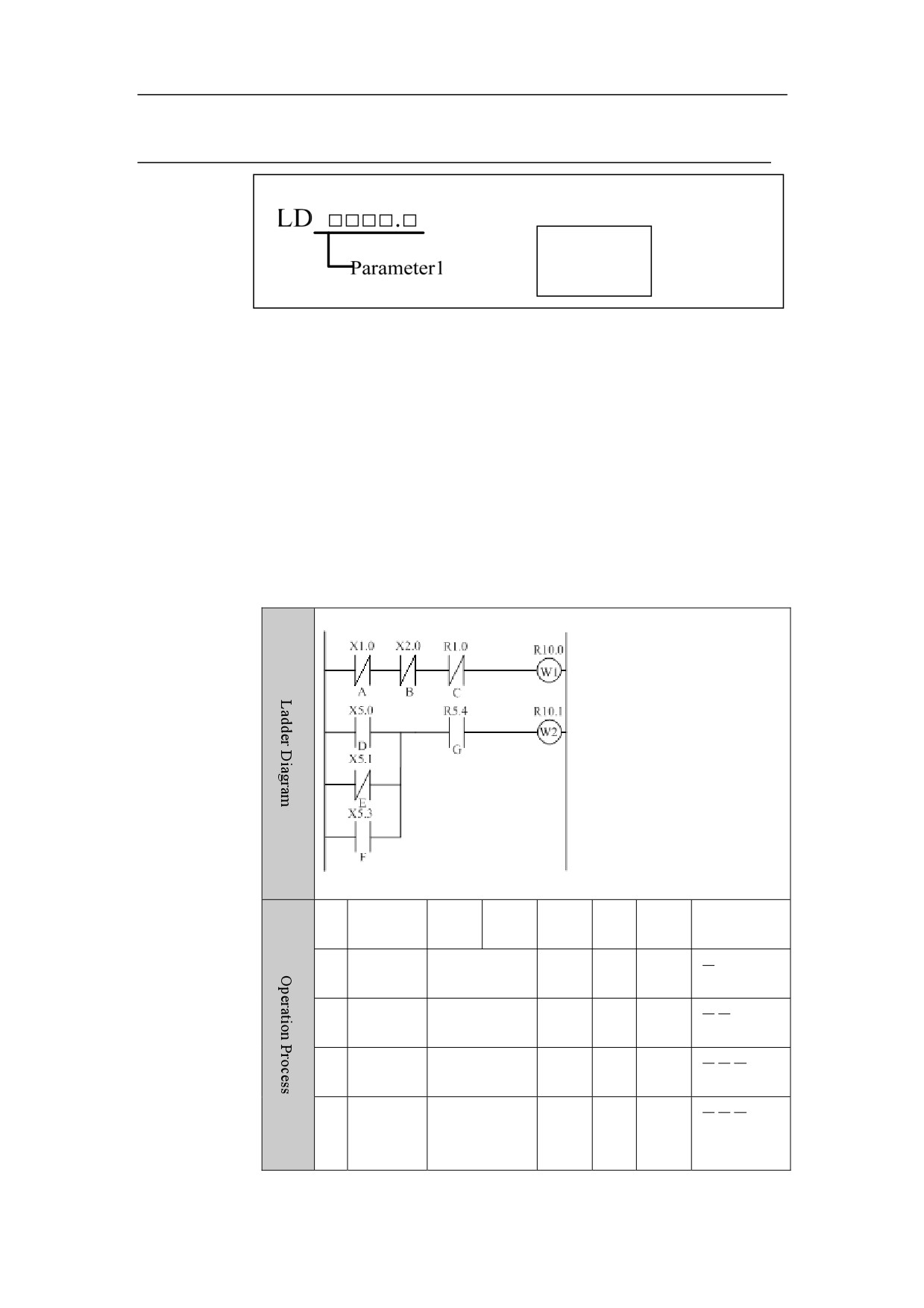
LD
Format
Parameter 1
Function
Read out status signal (1 or 0) of specified address, and save that signal in ST0.
It is used for the situation in which programming starts from the normal-open
node.
Parameter
Register point parameter
Example
N
Instructi
Addr
Bit
Refer
ST2
ST1
ST0
o.
on
ess
No.
ance
LDI
X1 .
0
A
1
A
ANI
X2 .
0
B
2
A.B
ANI
R1 .
0
C
3
AB
OUT
R10 .
0
Outp
4
AB
ut
W1
19

HNC-8-PLC Programming specification
2. Basic instruction
LD
X5 .
0
D
D
5
ORI
X5 .
1
E
D+
E
6
OR
X5 .
3
F
D+E + F
7
AND
X5 .
4
G
(
D
+ E + F).G
8
OUT
R10 .
0
Outp
(
D
+ E + F).G
9
ut
W2
Desc
riptio
n
20
HNC-8-PLC Programming specification
2. Basic instruction
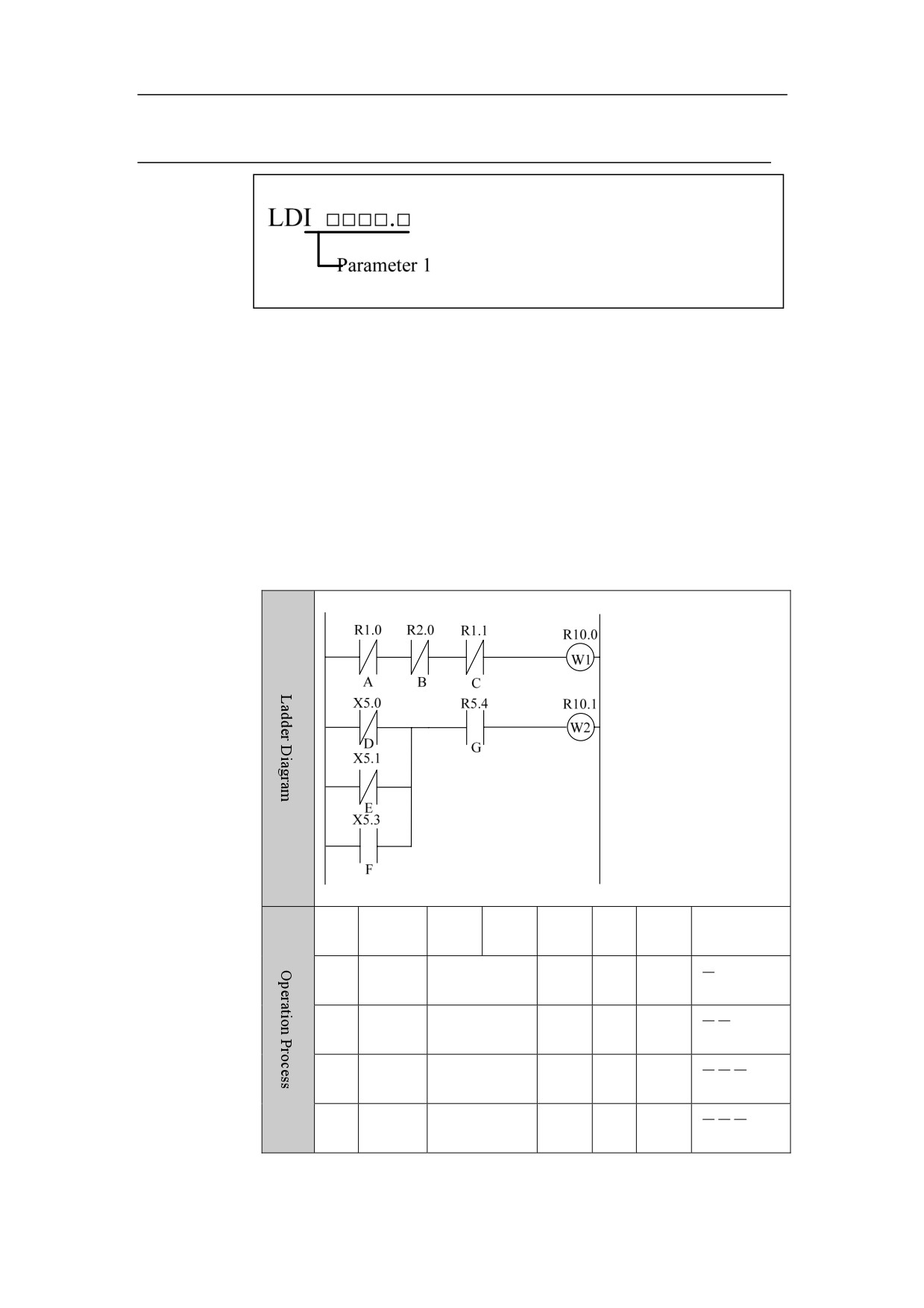
LDI
Format
Function
Read out status signal (1 or 0) of specified address, and save that inverted signal
in ST0. It is used for the situation in which programming starts from
normal-closed node.
Parameter
Register point parameter
Example
No.
Instruct
Addr
Bit
Refer
ST2
ST1
ST0
ion
ess
No.
ence
LDI
R1 .
0
A
1
A
ANI
R2 .
0
B
2
A.B
ANI
R1 .
1
C
3
AB
OUT
R10 .
0
W1
4
AB
21

HNC-8-PLC Programming specification
2. Basic instruction
LDI
X5 .
0
D
5
D
ORI
X5 .
1
E
6
D+
E
OR
X5 .
3
F
7
D+E + F
AND
R5 .
4
G
8
(
D
+ E + F.)G
OUT
R10 .
1
W2
9
(
D
+ E + F.)G
Desc
riptio
n
22
HNC-8-PLC Programming specification
2. Basic instruction
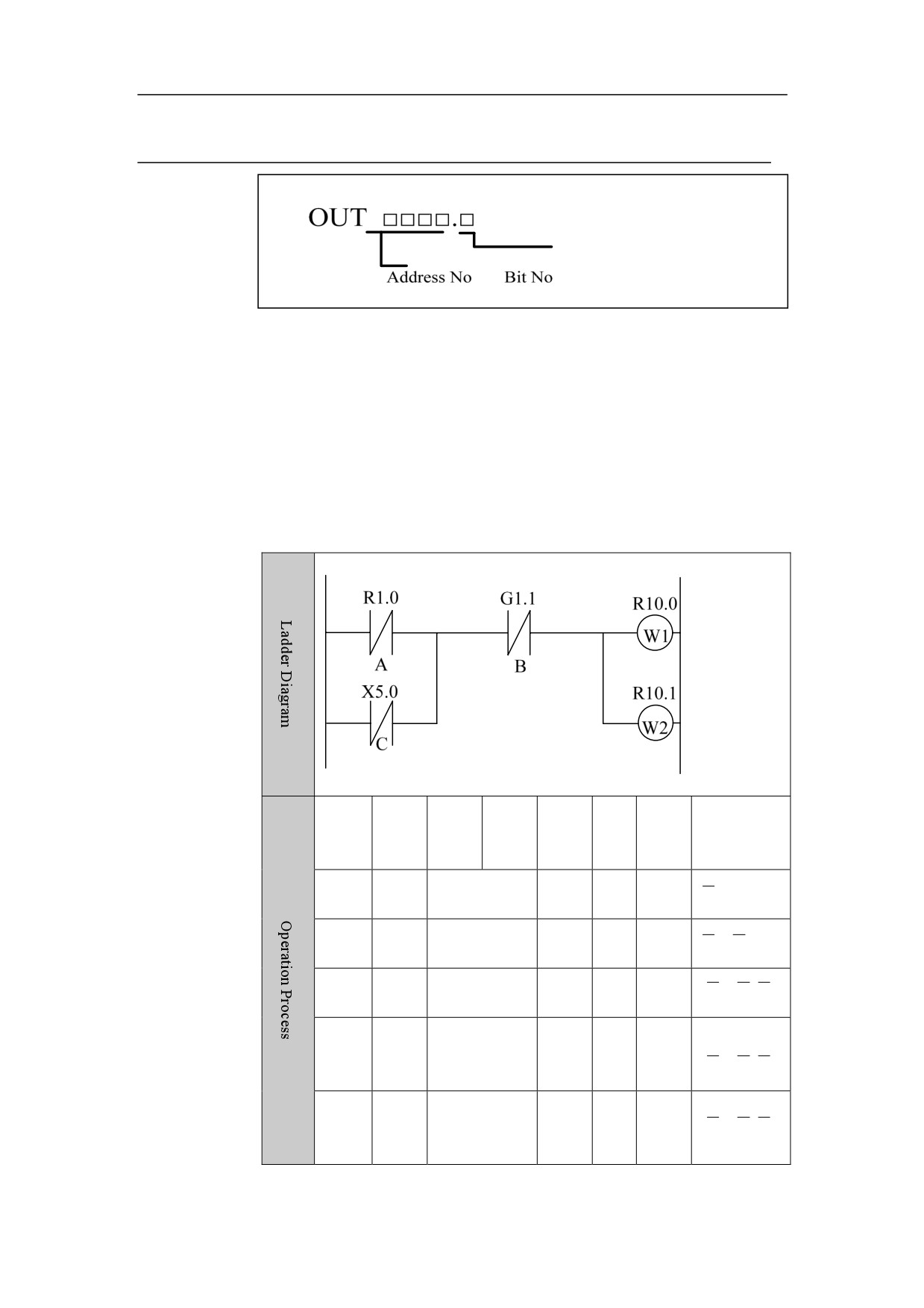
OUT
Format
Function
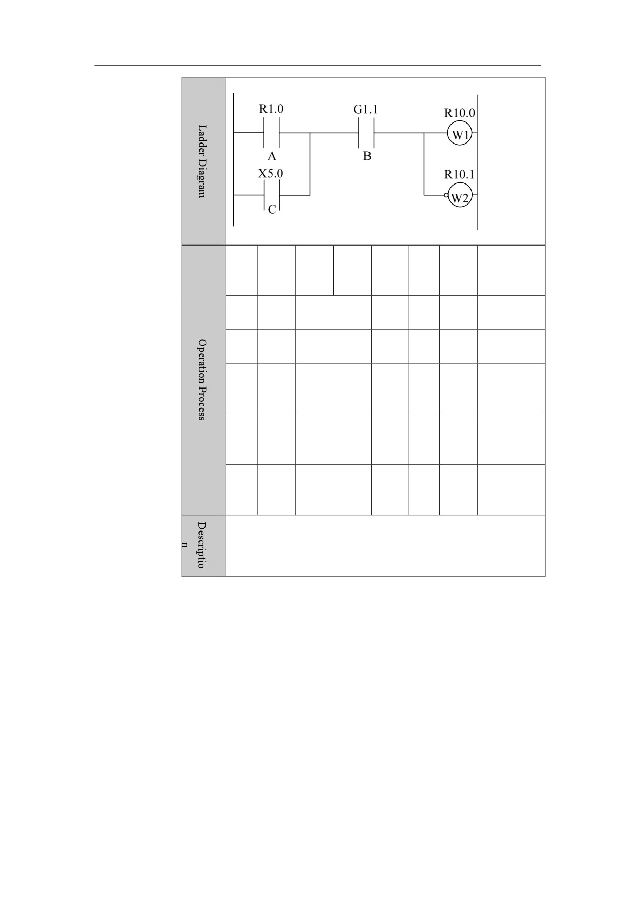
Output result of logic operation (status of ST0) to the specified address. It is
used to output the result to one or more than one addresses.
Parameter
Register point parameter
Example
No.
Instr
Addr
Bit
Refer
ST2
ST1
ST0
uctio
ess
No.
ence
n
LDI
R1 .
0
A
1
A
ORI
X5 .
0
C
2
A+C
ANI
G1 .
1
B
3
(
A .
OUT
R10 .
0
W1
4
(
A .
5
OUT
R10 .
1
W2
(
A .
23
HNC-8-PLC Programming specification
2. Basic instruction
Desc
Cases about series circuit and parallel circuit
riptio
n
24

HNC-8-PLC Programming specification
2. Basic instruction
OOUT
Format
Function
Output result of inverted logic operation (status of ST0) to the specified
address.
It is used to output the result to one or more than one addresses.
Parameter
Register point parameter
25
HNC-8-PLC Programming specification
2. Basic instruction
Example
No.
Instr
Addr
Bit
Refer
ST2
ST1
ST0
uctio
ess
No.
ence
n
1
LD
R1 .
0
A
A
2
OR
X5 .
0
C
A+C
3
AND
G1 .
1
B
(A + C
4
OUT
R10 .
0
W1
(A + C
5
OOU
R10 .
1
W2
(A + C
T
26
HNC-8-PLC Programming specification
2. Basic instruction
SET
Format
Function
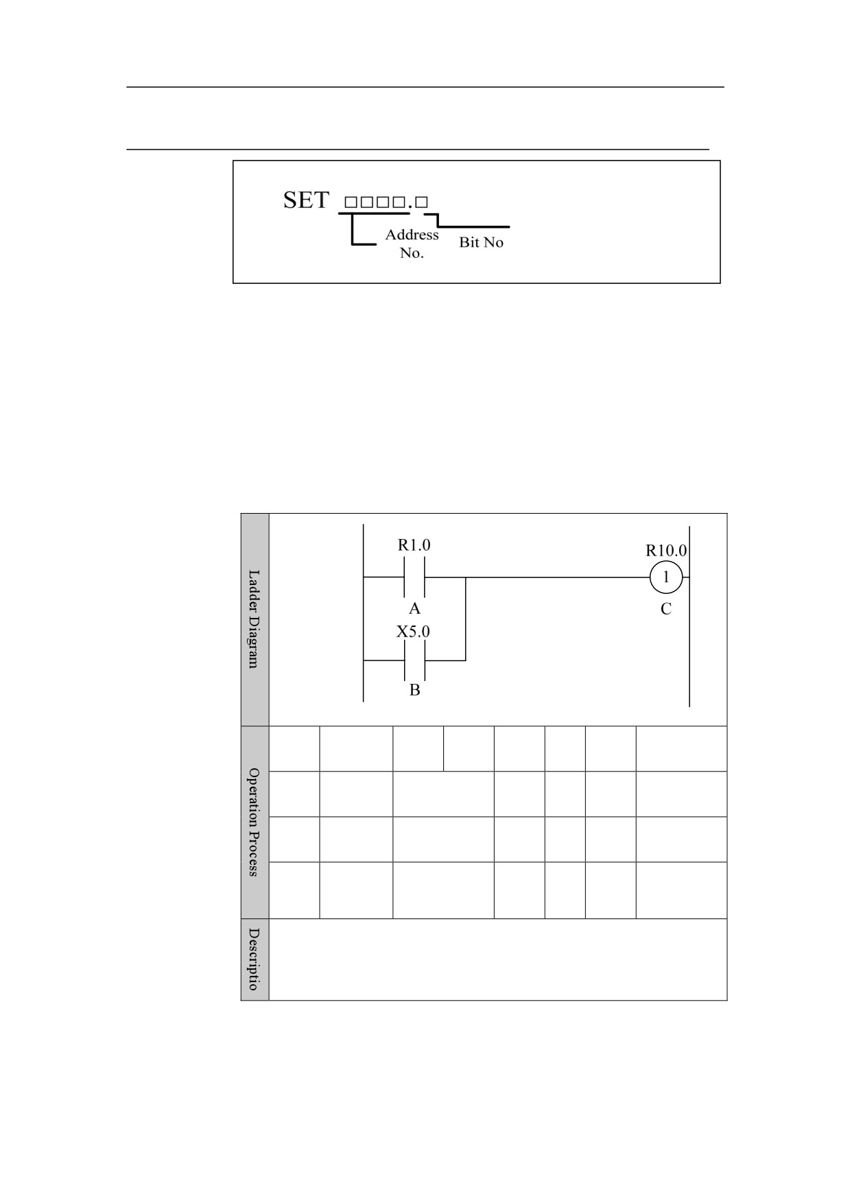
Logic OR the result of logic operation (ST0) to the specified address, which
then is output to the same address.
Parameter
Register point parameter
Example
No.
Instructi
Addr
Bit
Refer
ST2
ST1
ST0
on
ess
No.
ence
1
LD
R1 .
0
A
A
2
OR
X5 .
0
B
A+B
3
SET
R10 .
0
C
A+B
27
HNC-8-PLC Programming specification
2. Basic instruction
RST
Format
Function
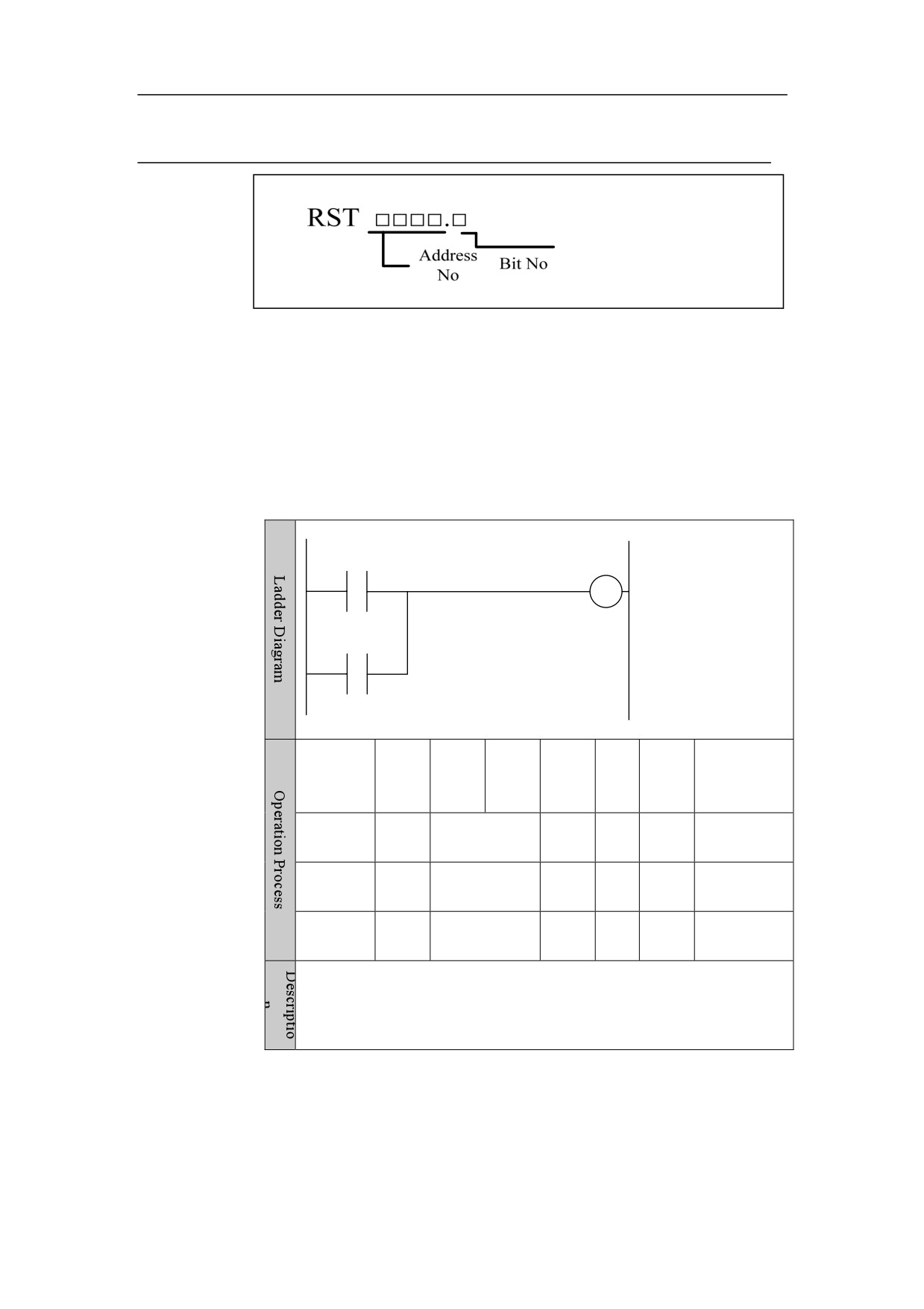
Logic AND the inverted result of logic operation (ST0) to the specified
address, which then is output to the same address.
Parameter
Register point parameter
Example
R1.0
R10.0
0
A
C
X5.0
B
No.
Instr
Addr
Bit
Refer
ST2
ST1
ST0
uctio
ess
No.
ence
n
1
LD
R1 .
0
A
A
2
OR
X5 .
0
B
A+B
3
RST
R10 .
0
C
A+B
28
HNC-8-PLC Programming specification
2. Basic instruction
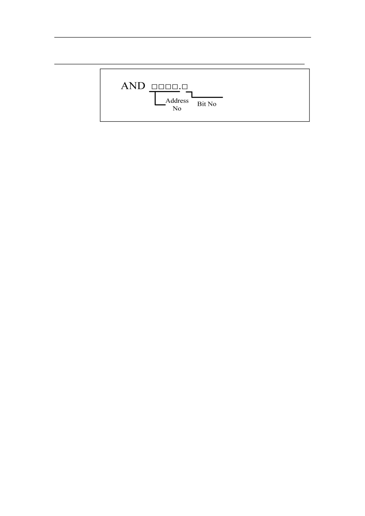
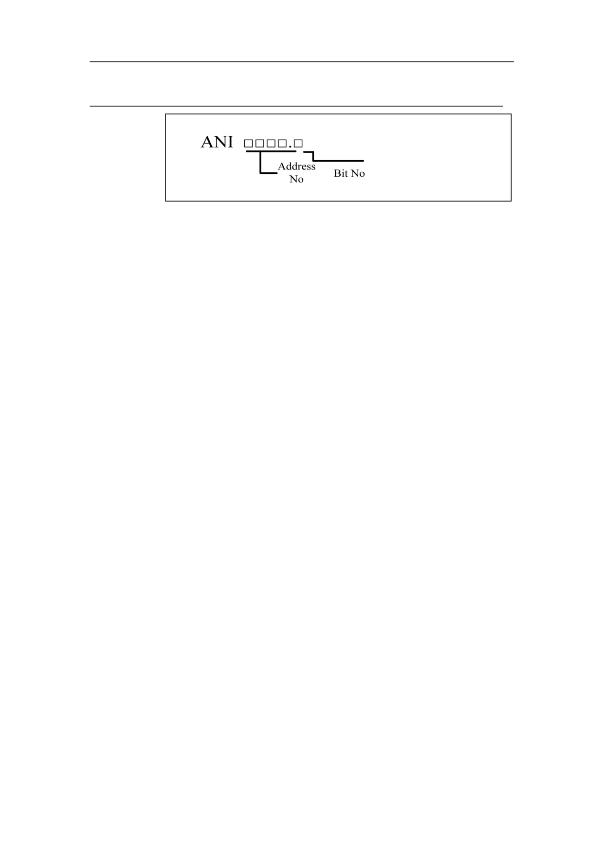
AND
Format
Function
Logic AND
Parameter
Register point parameter
Example
See the example for LD instruction
29
HNC-8-PLC Programming specification
2. Basic instruction
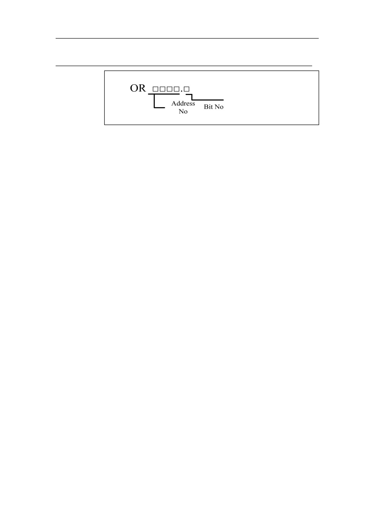
ANI
Format
Function
Logic AND NOT
Parameter
Register point parameter
Example
See the example for LD instruction
30
HNC-8-PLC Programming specification
2. Basic instruction
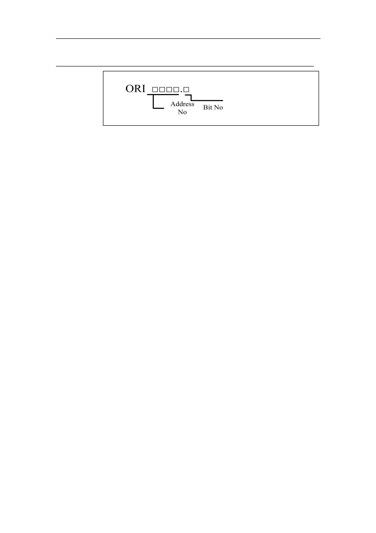
OR
Format
Function
Logic OR
Parameter
Register point parameter
Example
See the example for LDI instruction
31
HNC-8-PLC Programming specification
2. Basic instruction
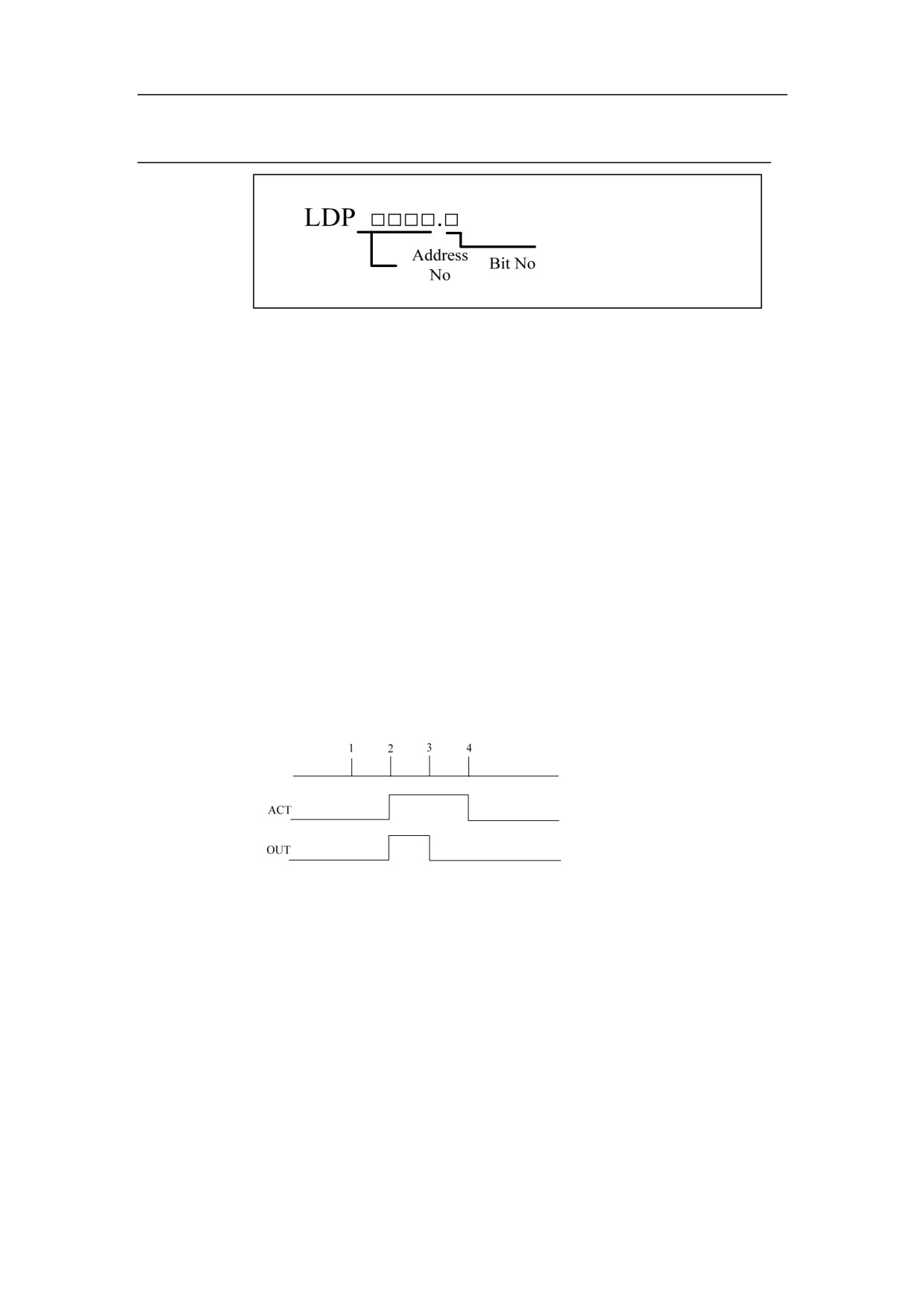
ORI
Format
Function
Logic OR NOT
Parameter
Register point parameter
Example
See the example for LDI instruction
32
HNC-8-PLC Programming specification
2. Basic instruction
LDP
Format
Function
Get rising edge of trigger element signal, and save the signal in ST0.
Set input signal to 1 in the next scanning period of the rising edge of input
signal.
It is used for the situation in which programming starts from elements of
rising edge.
Parameter
Register point parameter
Control
Input signal: Set output signal to 1 at the rising edge of signal(0->1).
condition
Output signal: During operation, input signal keeps 1 within one PLC scanning
period.
Operation
33
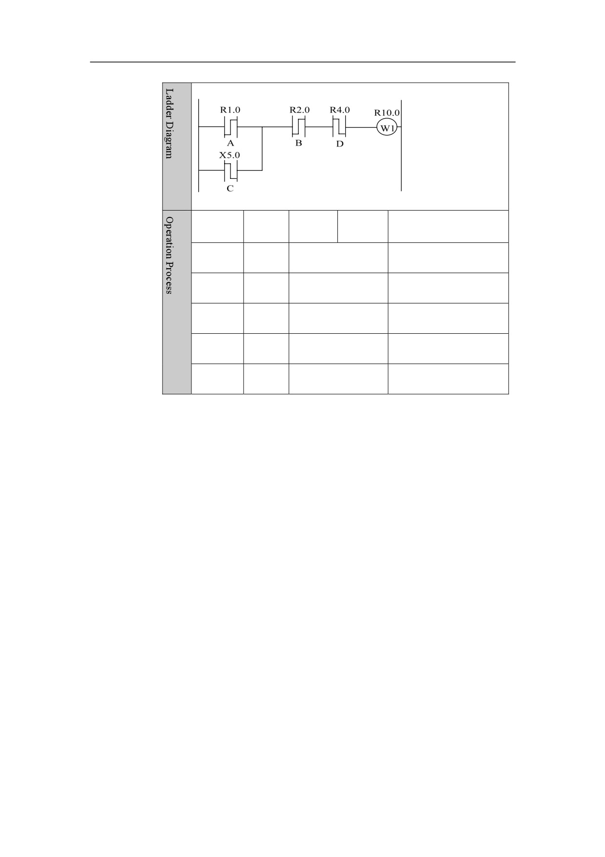
HNC-8-PLC Programming specification
2. Basic instruction
Example
No.
Instruct
Address
Bit No.
Referance
ion
1
LDP
R1 .
0
Rising edge of A
2
ORF
X5 .
0
Falling edge of B
3
ANDP
R2 .
0
Rising edge of C
4
ANDF
R4 .
0
Falling edge of D
5
OUT
R10 .
1
Output W1
34
HNC-8-PLC Programming specification
2. Basic instruction
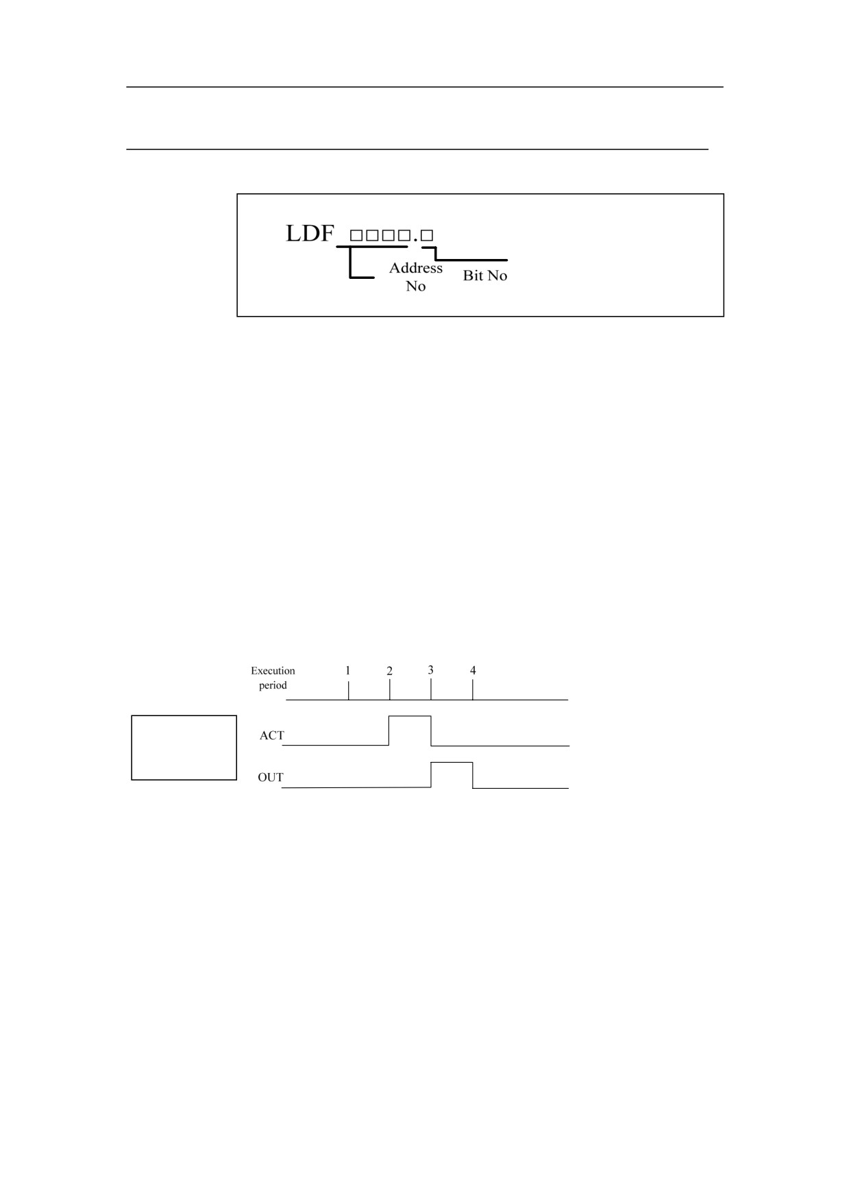
LDF
Format
Function
Get falling edge of trigger element signal, and save the signal in ST0.
Set input signal to 1 in the scanning period of the falling edge of input signal.
It is used for the situation in which programming starts from elements of
falling edge.
Parameter
Register point parameter
Control
Input signal: Set output signal to 1 at the falling edge of signal(1->0).
condition
Output signal: During operation, input signal keeps
1 within one PLC
scanning period.
Operation
Execution
period
Example
See the example for LDP instruction
35
HNC-8-PLC Programming specification
2. Basic instruction
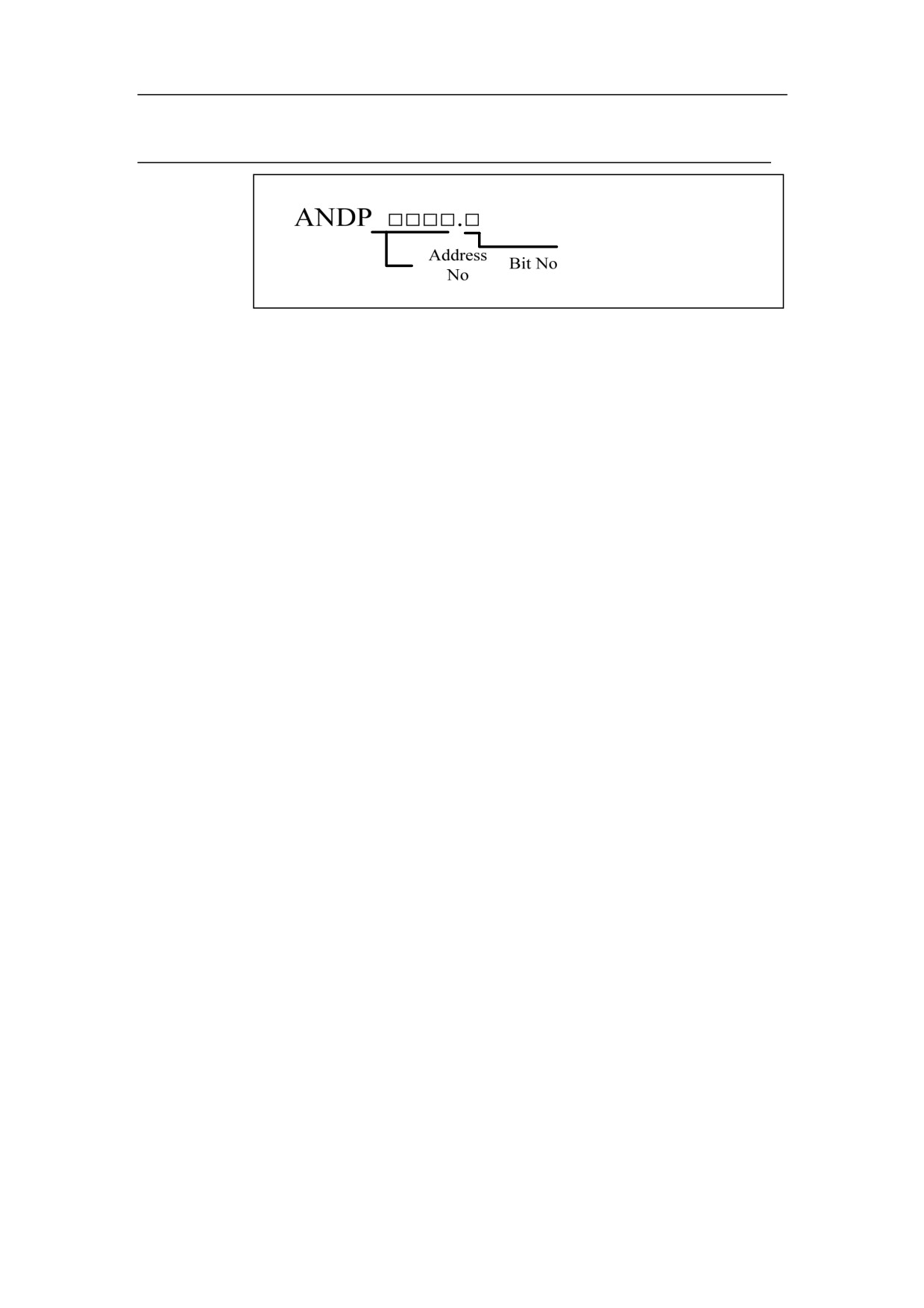
ANDP
Format
Function
Logic AND rising edge
Parameter
Register point parameter
Example
See the example for instruction LDP
36
HNC-8-PLC Programming specification
2. Basic instruction
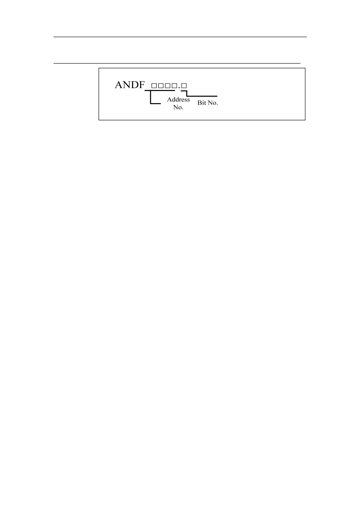
ANDF
Format
Function
Logic AND falling edge
Parameter
Register point parameter
Example
See the example for instruction LDP
37
HNC-8-PLC Programming specification
2. Basic instruction
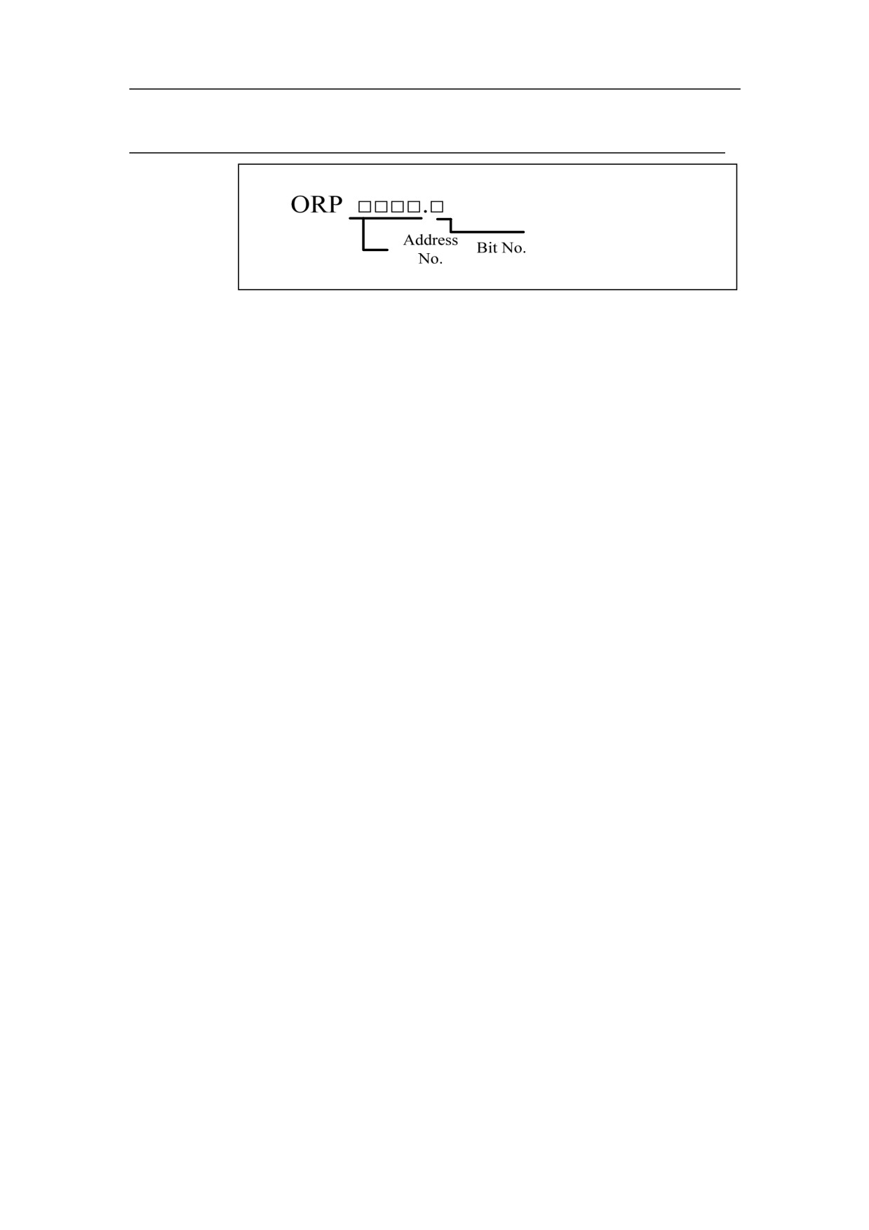
ORP
Format
Function
Logic OR rising edge
Parameter
Register point parameter
Example
See the example for instruction LDP
38
HNC-8-PLC Programming specification
2. Basic instruction
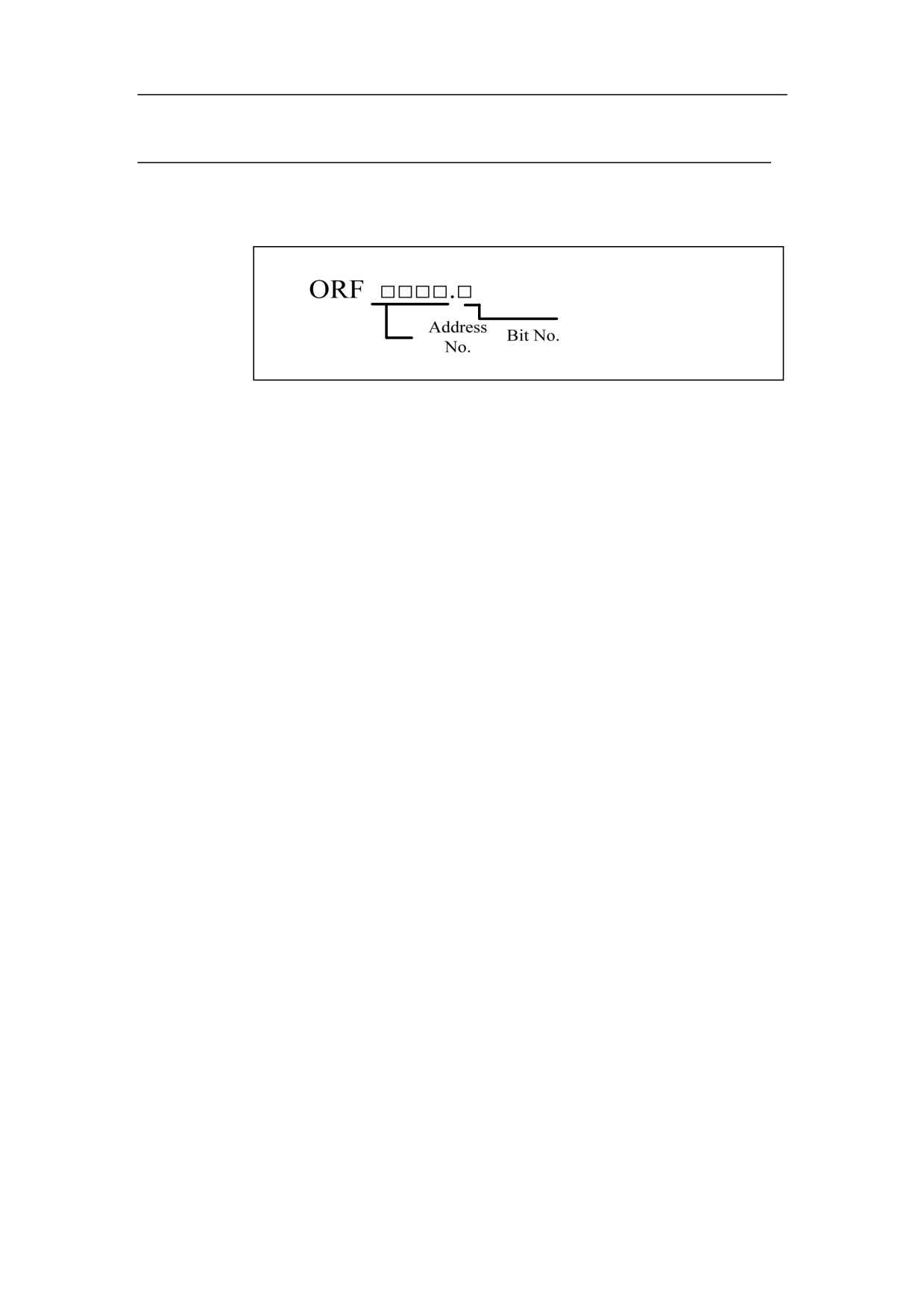
ORF
Format
Function
Logic OR falling edge
Parameter
Register point parameter
Example
See the example for instruction LDP
39
HNC-8-PLC Programming specification
2. Basic instruction
ORB
Format
ORB
Function
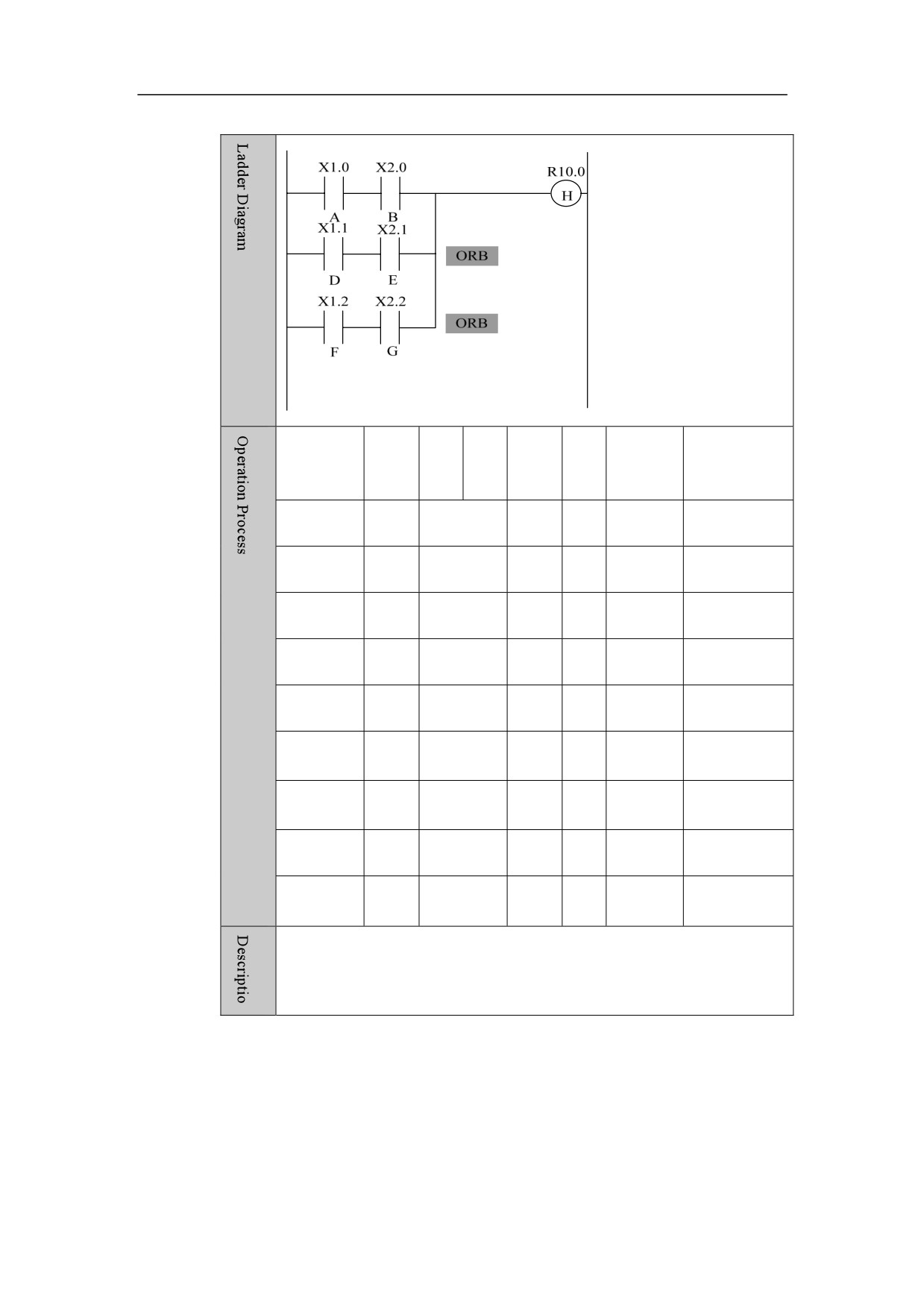
1) ORB is independent, and doesn’t need to connect with other elements or
function blocks.
2) ORB is to connect two or more series circuits that contain more than one
series blocks or contain the series ANB blocks.
3)Start the programming with LD or LDI, and have all series block being in
parallel via ORB.
Parameter
No parameter
Example
40
HNC-8-PLC Programming specification
2. Basic instruction
No.
Instr
Add
Bit
Refer
ST2
ST1
ST0
uctio
ress
No.
ance
n
1
LD
X1 .
0
A
A
2
AND
X2 .
0
B
A.B
3
LD
X1 .
1
D
D
4
AND
X2 .
1
E
D.E
5
ORB
A.B+
6
LD
X1.
2
F
A.B+
F
7
AND
X2.
2
G
A.B+
F.G
8
ORB
AB+D.E+F.G
9
OUT
R10.
1
H
AB+D.E+F.G
41
HNC-8-PLC Programming specification
2. Basic instruction
ANB
Format
ANB
Function
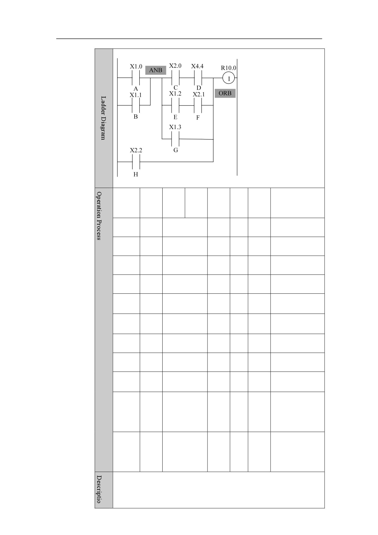
1) ANB is independent, and doesn’t need to connect with other elements or
function blocks.
2) ANB is to connect two or more parallel circuits that contain more than one
parallel-connected blocks or contain the parallel ORB blocks.
3)Starts programming with LD or LDI, and have all series block being in
parallel via ORB.
Parameter
No parameter
Example
42
HNC-8-PLC Programming specification
2. Basic instruction
No.
Instr
Addr
Bit
Refer
ST2
ST1
ST0
uctio
ess
No.
ence
n
1
LD
X1 .
0
A
A
2
OR
X1 .
1
B
A+B
3
LD
X2 .
0
C
A+B
C
4
AND
X4.
4
D
A+B
C.D
5
LD
X1 .
2
E
A+BC.D
E
6
AND
X2 .
1
F
A+BC.D
E.F
7
ORB
A+B
C.D + E.F
8
OR
X1.
3
G
A+B
C.D+
9
ANB
(
A+B.C.D+E.F+G
)
10
OR
X2.
2
H
(A+B
).(CD+E.F+G
)
+H
11
OUT
R10.
0
I
(A+B
).(CD+E.F+G
)
+H
43
HNC-8-PLC Programming specification
2. Basic instruction
MPS、MRD、MPP
Format
MPS
MRD
MPP
Function
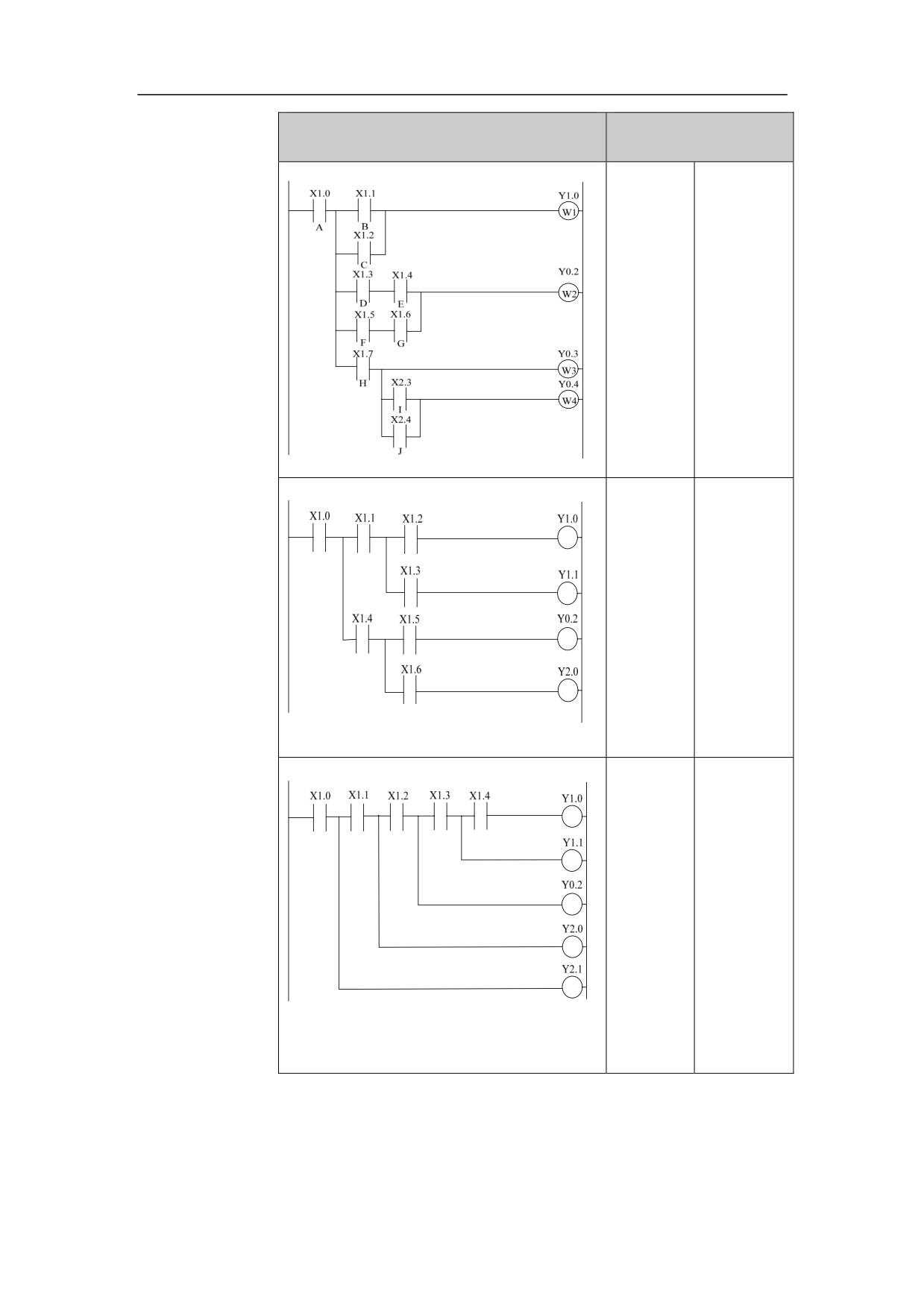
1) MPS Stores signal states of this point, waiting to be used when other lines
are output.
2) MRD reads signal from last storage point, connects to the next node, of
which signal status is always the same.
3) MPP brings up signal status from this storage point, connects to the next
node, and removes the status of this node.
4) Every MPS must ends with MPP.
5) The last connection line must be ended with MPP.
Parameter
No parameter
44
HNC-8-PLC Programming specification
2. Basic instruction
Example
Ladder Diagram
Statement List
LD X1.0
AND X1.6
MPS
ORB
LD X1.1
ANB
OR X1.2
OUT Y0.2
ANB
MPP
OUT Y1.0
AND X1.7
MRD
OUT Y0.3
LD X1.3
LD X2.3
AND X1.4
OR X2.4
LD X1.5
ANB
(followe
OUT Y0.4
d by the
right)
LD X1.0
OUT Y1.1
MPS
MPP
AND X1.1
AND X1.4
MPS
MPS
AND X1.2
AND X1.5
OUT Y1.0
OUT Y0.2
MPP
MPP
AND X1.3
AND X1.6
(followe
OUT Y2.0
d by the
right)
LD X1.0
OUT Y1.0
MPS
MPP
AND X1.1
OUT Y1.1
MPS
MPP
AND X1.2
OUT Y0.2
MPS
MPP
AND X1.3
OUT Y2.0
MPS
MPP
AND X1.4
OUT Y2.1
(followe
d by the
right)
45
HNC-8-PLC Programming specification
3. Basic component
Basic Element
This chapter includes the sections as following:
3.1 Normal-open Contact
3.2 Normal-close Contact
3.3 True contact
3.4 Rising edge of Contact
3.5 Falling edge of Contact
3.6 Logic Output
3.7 Inverted Logic Output
3.8 Setting Output
3.9 Reset Output
46
HNC-8-PLC Programming specification
3. Basic component
Normal-open Contact
Symbol
Paramet
Paramet
Storage
Explanat
Data type
Properties
er
er form
area
ion
X、Y、F、
Pre
○
Register
<Addres
G、R、W、
□□□□。□
BOOL
bit to be
s>
D、P、T、
Post
√
checked
C、B
Function
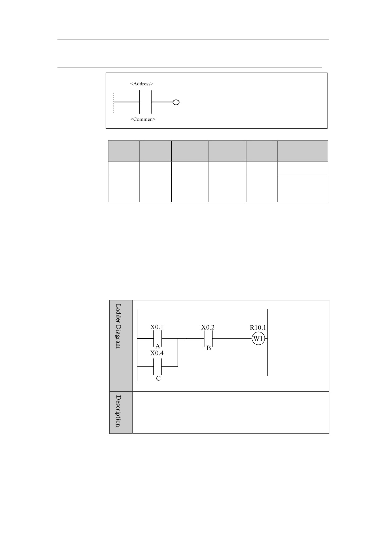
When the bit saved in the specified address is “1”, the normal-open contact
is closed; If the contact is closed, the signal will flow through this contact.
Parameter
Parameter 1: register point parameter, in the form of X0.1.
Example
When signal of X0.1 or X0.4 is “1”, and X0.2 signal is “1”, the
current is conducted, with R10.1 being output.
47