HNC-8 Numerical Control System Software. Maual of PLC Programming (V1.24) - page 1
HNC-8 Numerical Control System Software
Maual of PLC Programming
V1.24
2016-02
Wuhan Huazhong Numerical Control Co., Ltd.
HNC-8-PLC Programming specification
Catalog
Content
CONTENT
错误!未定义书签。
PREFACE
1
OVERVIEW
3
SPECIFICATIONS OF PLC
4
SEQUENTIAL PROGRAM NOTION
5
ALLOCATION INTERFACE
6
SEQUENTIAL PROGRAM
7
SEQUENTIAL PROGRAM COMPOSITION
12
ADDRESS
14
BASIC INSTRUCTION
15
LD
19
LDI
21
OUT
23
OOUT
25
SET
27
RST
28
AND
29
HNC-8-PLC Programming specification
Catalog
ANI
30
OR
31
ORI
32
LDP
33
LDF
35
ANDP
36
ANDF
37
ORP
38
ORF
39
ORB
40
ANB
42
MPS、MRD、MPP
44
BASIC ELEMENT
46
NORMAL-OPEN CONTACT
47
NORMAL-CLOSE CONTACT
48
TRUE CONTACT
49
RISING EDGE OF CONTACT
50
FALLING EDGE OF CONTACT
51
HNC-8-PLC Programming specification
Catalog
LOGIC OUTPUT
52
INVERTED LOGIC OUTPUT
53
SETTING OUTPUT
54
RESET OUTPUT
55
BASIC FUNCTION MODULE
56
CONTROL INSTRUCTION
57
Instructin M Get MGET
57
M Instruction Response MACK
58
T Instruction Get TGET
59
T Instruction Response TACK
60
Handwheel Control RTOMPG
61
Thermal Error Compensation Module TEMPSEN
62
MATHEMATICAL OPERATION
64
Addition ADD
64
Subtraction SUB
66
Multiplication MUL
68
Division DIV
70
Increase One INC
72
HNC-8-PLC Programming specification
Catalog
Decrease One DEC
73
Logic AND WAND
74
Logic OR WOR
75
Logic XOR WXOR
77
Complement NEG
79
COUNTER
80
Plus-minus Counter CTR
80
Counter CTRC
82
Custom Plus-minus Counter CTUD
84
TIMER
86
Delay-on Timer TMRB
86
Delay-off Timer STMR
88
PROCESS CONTROL
90
Initialization Module End IEND
90
PLC1 Module End 1END
91
PLC2 Module End 2END
92
Jump JMP
93
Label LBL
94
HNC-8-PLC Programming specification
Catalog
Call Subprogram CALL
95
Subprogram Start SP
96
Subprogram End SPE
97
Subprogram Return RETN
98
Loop LOOP
99
Next Loop NEXT
100
COMPARISON
101
Comparison CMP
101
Lower Than LT
103
Area Comparison ACMP
104
Consistency Comparison COIN
105
DATA MANIPULATION
106
Moving Data MOV
106
Relative Moving Data XMOV
107
Batch Moving BMOV
109
Multiple Moving Data FMOV
111
Data Exchange XCH
113
Data Reset ZRST
115
HNC-8-PLC Programming specification
Catalog
Encoding ENCO
116
Decoding DECO
118
Transformation COD
120
Data Search SER
122
Register Merging ASSEM
124
Register Decomposition DISAS
126
Area Conversion ACVT
128
Alternate Output ALT
130
Fetch Rising Edge PLS
131
Fetch Falling edge PLF
132
Points Transformation PTN
133
Number Conversion NTP
135
Part Count PARTCNT
137
Part-counting Clear PARTCLR
138
Temperature Collection Module HEADSEN
140
STATUS WORD AND CONTROL WORD PROGRAMMING
142
INTRODUCTION ON STATUS WORD AND CONTROL WORD
143
Axis Status Word
145
HNC-8-PLC Programming specification
Catalog
Axis Control Word
150
Channel Status Word
154
Channel Control Word
158
EXAMPLE OF STATUS WORD AND CONTROL WORD PROGRAMMING
164
Work Pattern Setting
164
Work Pattern Getting
165
Control of Feed Axis and Spindle
166
Home
167
Incremental Rate Override
168
Cycle Start and Feed Hold
169
EXTENSION FUNCTION MODULE
170
NC FUNCTION
171
Channel Mode Setting MDST
171
Channel Mode Getting MDGT
173
Mode MDI
175
Locking Channel MST
176
Cycle Start CYCLE
177
Emergency Stop STOP
178
HNC-8-PLC Programming specification
Catalog
Reset RESET
179
Channel Exchange CHANSW
180
Feed Hold Start HOLD
181
Cycle Start LED CYCLED
182
Feed Hold LED HOLDLED
183
Block Skip(G31)ESCBLK
184
Rapid Override RPOVRD
186
Feedrate Override FEEDOVRD
187
Spindle Override SPDLOVRD
188
Incremental (Stepping) Rate STEPMUL
190
Dryrun DRYRUN
191
Block Skip SKIP
192
User Input USERIN
193
User Output USEROUT
194
Selection Stop SELSTOP
196
Vector Tool Direction Setting TOOLSET
197
Vector Tool Direction Clear TOOLCLR
198
8-bit Nixie Tube NIXIE
199
HNC-8-PLC Programming specification
Catalog
Tool Display TOOLUSE
201
FUNCTIONAL UNIT OF AXIS
202
Spindle JOG SPDLJOG
202
Spindle Control【Servo Spindle】SPDLBUS
203
Spindle Control with Gear【Servo Spindle】SPDLBUS1
204
Spindle Orientation Enable SPDLORI
207
Completing Spindle Orientation SPDLOROK
208
Spindle Control【DA】SPDA
209
Zero Speed Detection for Spindle SPDLZERO
211
Spindle Speed Arrival SPDLRCH
212
Driven Axis Home SUBAXEN
213
Release Driven Axis DESYN
214
Axis Jog JOGSW
215
Axis Stepping STEPAXIS
216
Jog Velocity JOGVEL
217
Home Run HOMRUN
218
Home Run 1 HOMERUN1
219
Home Approaching Switch HOMESW
220
HNC-8-PLC Programming specification
Catalog
Home Completing HOMLED
221
Axis Enable AXEN
222
Axis Ready (Bust) AXRDY
223
Axis Lock AXISLOCK
224
Relative PMC Axis Movement AXISMOVE
225
Absolute PMC Axis Movement AXISMVTO
226
The Second Soft Limit of Axis AXLMF2
227
Block Switch in Positive Limit Direction AXISPLMT
228
Block Switch in Negative Limit Direction AXISNLMT
229
Handwheel MPGSET
230
Servo Enable (Bus) SVSW
231
Axis Mode AXISMODE
232
Axis Reference REFPT
233
During Axis Home AXISHOM2
234
During Axis Moving AXMOVING
235
SYSTEM FUNCTION
236
Rotation ROT
236
Alarm ALARM
238
HNC-8-PLC Programming specification
Catalog
Event EVENT
239
Save Data SAVEDATA
240
Reset Setting Ouput RSTCHK
241
Reset Clear RSTCLR
242
OPERATIONAL MONITORING AND ONLINE MODIFICATION FOR LADDER DIAGRAM 243
ONLINE DIAGNOSIS FOR LADDER DIAGRAM
245
SEARCH
249
CHANGE
251
Insert Straight Line
252
Insert Vertical Line
252
Delete Vertical Line
253
Delete Component
253
Normal Open
254
Normal Closed
255
Logical Output
255
Inverted Output
256
Functional Module
256
Return
257
HNC-8-PLC Programming specification
Catalog
COMMAND
258
Select
259
Delete
259
Move
260
Copy
263
Paste
264
Insert Line
264
Add Line
265
Return
266
LOAD
267
DISCARD
268
SAVE
269
RETURN
270
INSTRUCTION ON PLC DEVELOPMENT ENVIRONMENT
271
OVERVIEW
272
INSTALLATION OF DEVELOPMENT ENVIRONMENT
273
DEVELOPMENT ENVIRONMENT INTERFACE
276
Menu
276
HNC-8-PLC Programming specification
Catalog
Ladder Diagram Interface
279
Statement List Interface
281
Symbol List Interface
282
DEVELOPMENT ENVIRONMENT OPERATION
283
Symbol List Operation
283
Ladder Diagram Operation
287
Statement List Operation
293
APPENDIX A
296
HNC-8-PLC Programming specification
Preface
Preface
Reader
manual is for machine user, which covers PLC introductions on HNC-8
CNC and their use, programming methods, examples and the like.
The
Scope
The programming applies to HNC-8 numerical control system with V1.24.
Notes
of this manual is authorized, organized and implemented by Wuhan
Huazhong Numerical Control Co., Ltd. (HNC).
Without authorization or written permission, no entity or individual may
change the manual content. HNC will not be responsible for any losses
caused by that.
The matters which are not especially described in this manual are
regarded as “Impossible” or “Not Allowed”.
Updates
The copyright of this manual is subject to Wuhan Huazhong Numerical
and
Control Co., Ltd
(HNC). Any publishing and copy by other units or
upgrades
individuals are illegal, who may be investigated for legal responsibility.
Technical
support
Marketing Department: 027-87180095,027-87180303
Fax:027-87180303
1
HNC-8-PLC Programming specification
Preface
E-mail
:
Zip Code:430223
market@h
Address:HUST Park, Miaoshan Region, East-lake Development Zone,
uazhongcn
Wuhan, Hubei Province, China
c.com
2
HNC-8-PLC Programming specification
1. PLC Summary
Overview
This chapter includes:
1.1 Specifications of PLC
1.2 Sequential Program Notion
1.3 Allocation Interface
1.4 Sequential Program
1.5 Sequential Program Composition
1.6 Address
3

HNC-8-PLC Programming specification
1. PLC Summary
Specifications of PLC
Specificatio
Different PLC types have different program capacities,
function
instruction
ns
counts, and usage range of register.
Specification
HNC8
Programming language
Ladder,STL
Execution cycle of the first level
1ms
program
Program capacity
Ladder program
5000 lines
Statement list
10000 rows
Symbol name
1000
Instruction
Basic instruction,
Function instruction
Internal relay of single byte(R)
400 bytes (R0~~R399)
Internal relay of double-byte(W)
400 bytes (W0~~W199)
Internal relay of four-byte(D)
400 bytes (D0~~D99)
Timer (T)
128 (T0~~T127)
Counter (C)
128
(C0~~C127)
Subprogram (S)
——
Label
(L)
——
User-defined parameter (P)
200 (P0~~P199)
Holding storage area
Timer (T)
128 (T300~~T427)
Counter (C)
128 (C300~~C427)
Four-byte register(B)
200 bytes(B0~~B49)
I/O module(X)
X0~~X512
(Y)
Y0~~Y512
4
HNC-8-PLC Programming specification
1. PLC Summary
Sequential Program Notion
Notion
A brief description on sequential program is provided before on programming.
Sequential program indicates that, the program which logically controls the
machine and its relevant devices. For the personnel of electrical automation
control engineering, the widely-used control flow is based on sequential control,
from which, sequential program, a programming method for PLC control, is
generated.
Numerical control system firstly converts the program to a format, then CPU
decodes and operates it. CPU rapidly reads each instruction in the storage, and
operates program via arithmetic operation. Sequential program starts from the
ladder diagram and other standard PLC languages. The ladder diagram can be
understood as the execution order of CPU arithmetic operation.
The above is performed by PLC programming software, the role of which is to
document sequential program.
5
HNC-8-PLC Programming specification
1. PLC Summary
Allocation Interface
Interface
PLC interacts with external devices by external I/O. After control object is
identified and relevant input/output signals are calculated, corresponding
interfaces can be allocated to devices.
For easier debugging to PLC of numerical control system, input/output points of
panel interfaces for series 818 have been fixed, and for that of other devices,
refer to the electrical principle drawing.
Allocation
Panel points have been allocated in the standard PLC programs of Series 8
system, user doesn’t need to change their definitions. At programming time, user
uses other intermediate registers instead of input/output registers, to program.
Several system interfaces bas been described in Appendix 7, to make a better
understand of panel point distribution of series 8. Y487 and Y488 are output
addresses of digital tubes on panel, X480 and X491 are panel input signals, and
Y480 and Y486 are panel output signals.
6
HNC-8-PLC Programming specification
1. PLC Summary
Sequential Program
PLC sequential control is achieved by software, and the principle of it is
different from that of common relay circuit. Thus, the principle of sequential
control should be fully understood at the time of designing PLC sequential
program.。
Execution
In general relay control circuit, each relay may operate at the same time. In the
of
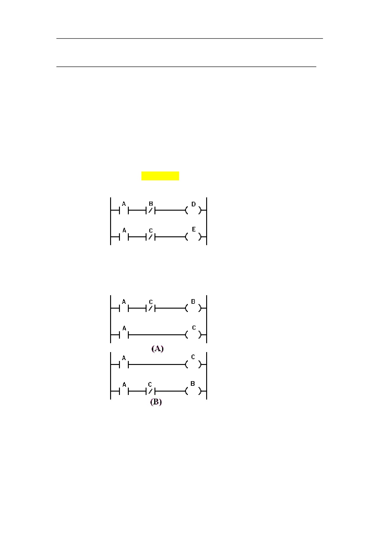
figure below, when relay A acts, relay D and E can act at the same time (in the
sequential
event of contact B and C being closed). In PLC sequential control, relays act in
program
sequence. When relay A operates, relay D operates first, and then relay E
operates (see figure 2.1(a)), that is, each relay operates in the order described in
the ladder diagram.
Figure 2.1 (a)
Figure A and B show the movement difference between relay circuit and PLC
program.
Figure2.1(b)
Relay
The actions in figure 2.1b(A) and figure 2.1b(B) are the same. After A (button
circuit
switch) is turned on, B and C are on, with current flowing through coil B and C.
B is cut off after C is switched on.
7
HNC-8-PLC Programming specification
1. PLC Summary
PLC
Similar with relay circuit, in figure 2.1b(A), after A (button switch) is turned on,
program
B and C are on, and B is switched off after a PLC program cycle. However, in
figure 2.1b(B), after A (button switch) is turned on, C is switched on, but B is not.
Loop
Sequential program executes from the beginning of the ladder diagram until the
execution
end, after that, it goes back to execute the begging of the ladder diagram again,
which is called loop execution.
That execution time from the begging to the end is called loop period. The loop
period of PLC2 depends on the controlled steps. The shorter the loop period, the
rapider the response of signal.
Prior execution
8
HNC-8-PLC Programming specification
1. PLC Summary
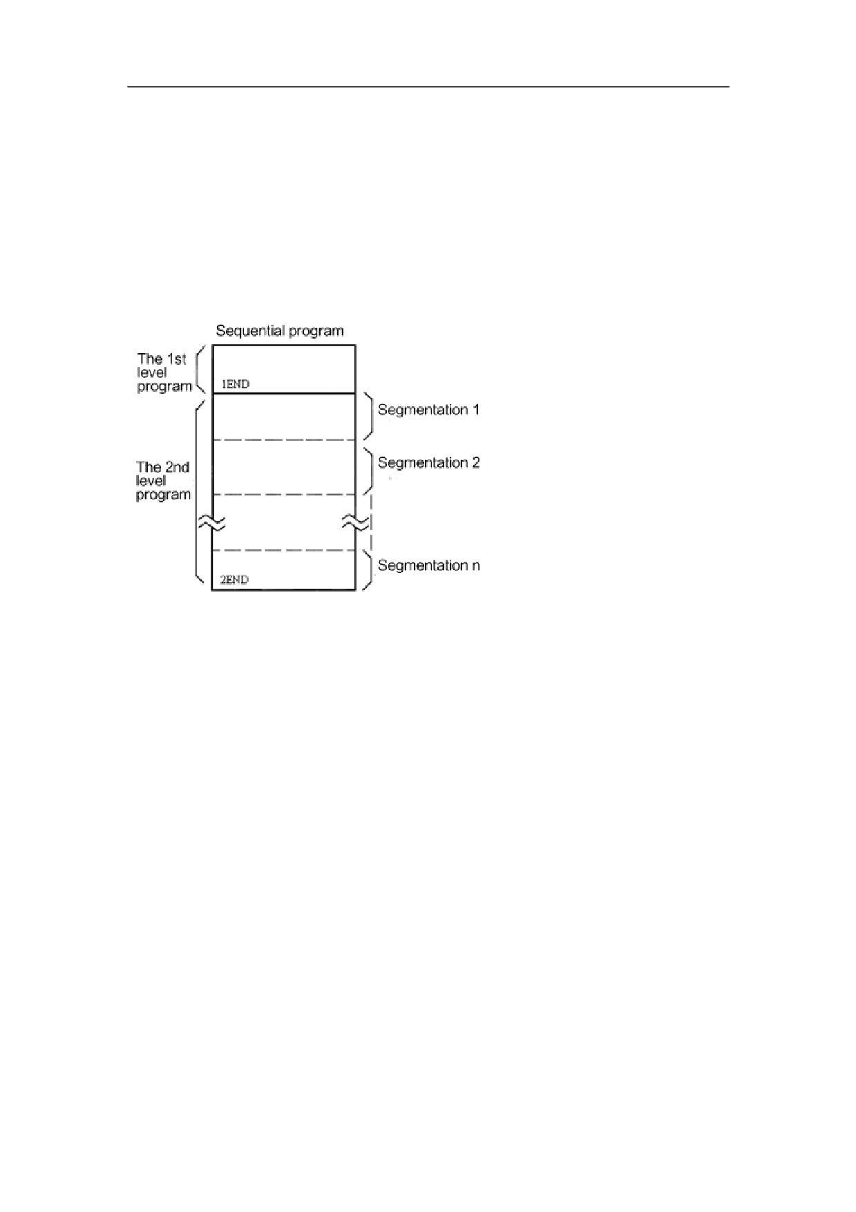
Sequential program consists of three parts: initialization program, the first level program, the
second level program.
The initialization program is performed once when system starts.
The first level program executes every 1ms.
If the first level is longer, the total execution time will be longer. Therefore, you should document
as short program of the first level as possible. The second level program can be automatically
seperated into n parts, and executes every n ms.
Segmentation of the second level program
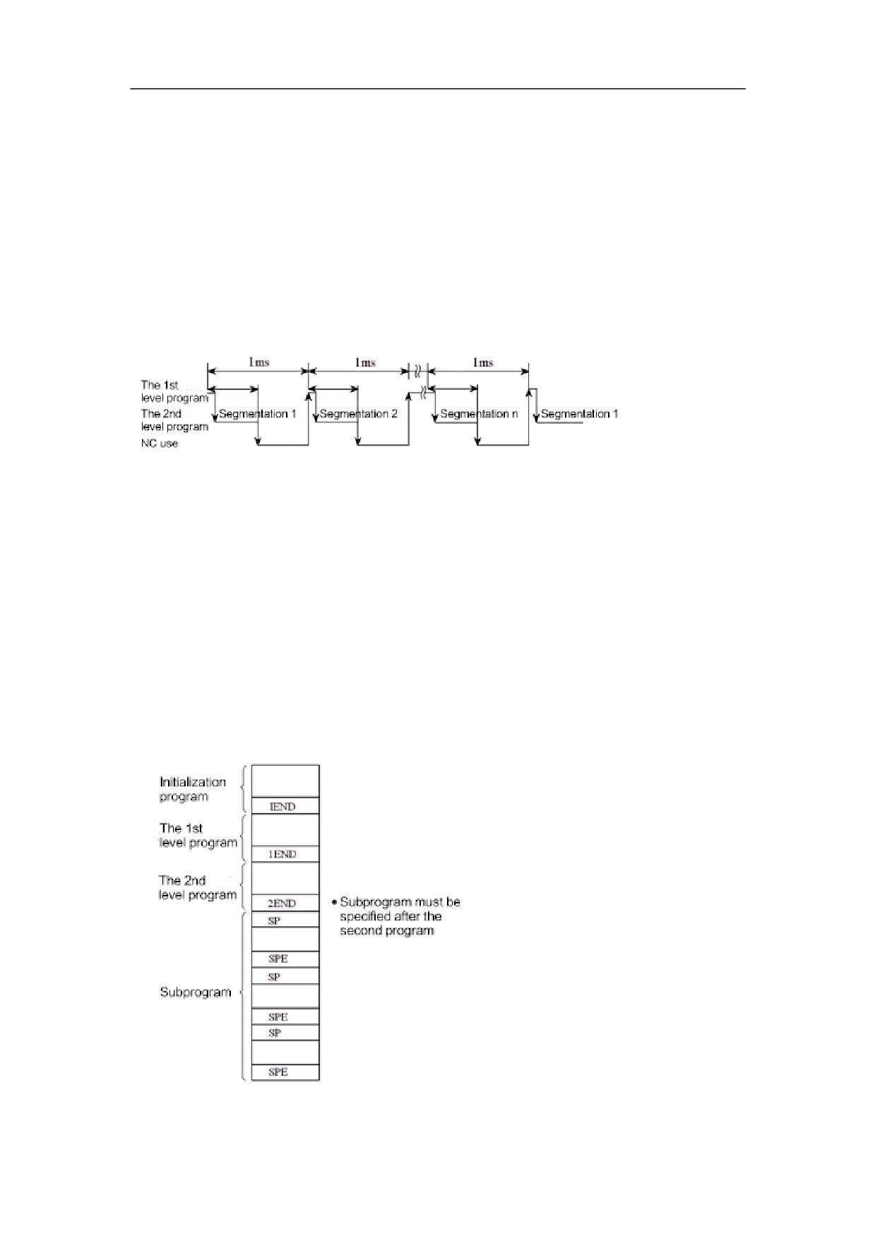
Segmentation of the second level program is to execute the first level program. When the number
of segmentations is n, the implementation process is as below diagram:
9
HNC-8-PLC Programming specification
1. PLC Summary
When the last part of the second level program has executed, the program starts from the
beginning again. In the event of n segmentations, the time for one loop execution is n ms (1ms X
n). The first level program executes every 1ms, and the second level program executes every n X
1ms. If the steps of the first level program increases, the steps of the second level program will
correspondingly decrease within 1ms, then more segmentations will be gotten, and program
processing time will be longer. For this reason, the first level program should be documented as
briefly as possible.
The first level program only handles short pulse signal, which includes emergency stop, axis
over-travel, and the like.
When subprogram is used, sequential program consists of:
10
HNC-8-PLC Programming specification
1. PLC Summary
11
HNC-8-PLC Programming specification
1. PLC Summary
Sequential Program Composition
Compositio
For traditional PLC, ladder diagram can be only established sequentially. The
n
ladder diagram language, which allows structured program, has the following
advantages:
The program is easily to be understood and documented.
It is more convenient to find out programming errors.
It is easy to find out reasons of causing errors.
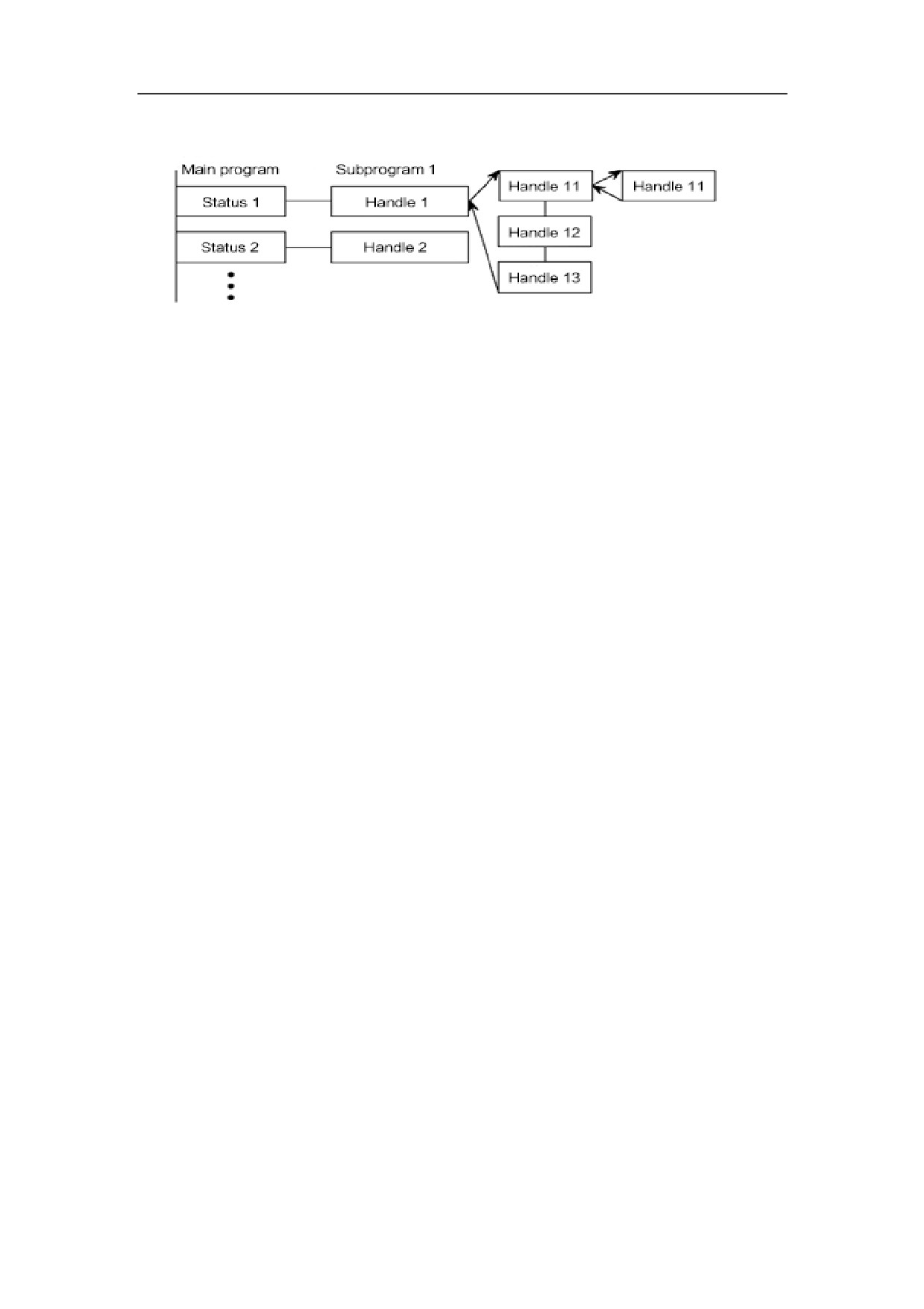
There are three main structured programming means
Subprogra
m
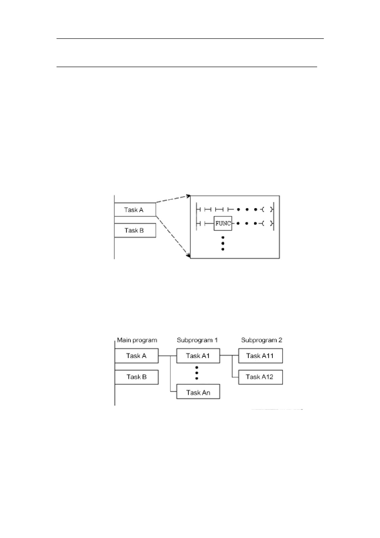
Subprogram regards the ladder diagram block as the processing unit.
Nesting
The combination of documented subprograms forms structured program.
Conditiona
l branch
Main program executes recurrently and detects whether condition is satisfied or
not. If condition is satisfied, corresponding subprogram is executed; if condition
is not satisfied, corresponding subprogram is not executed.
12
HNC-8-PLC Programming specification
1. PLC Summary
13
HNC-8-PLC Programming specification
1. PLC Summary
Address
Address
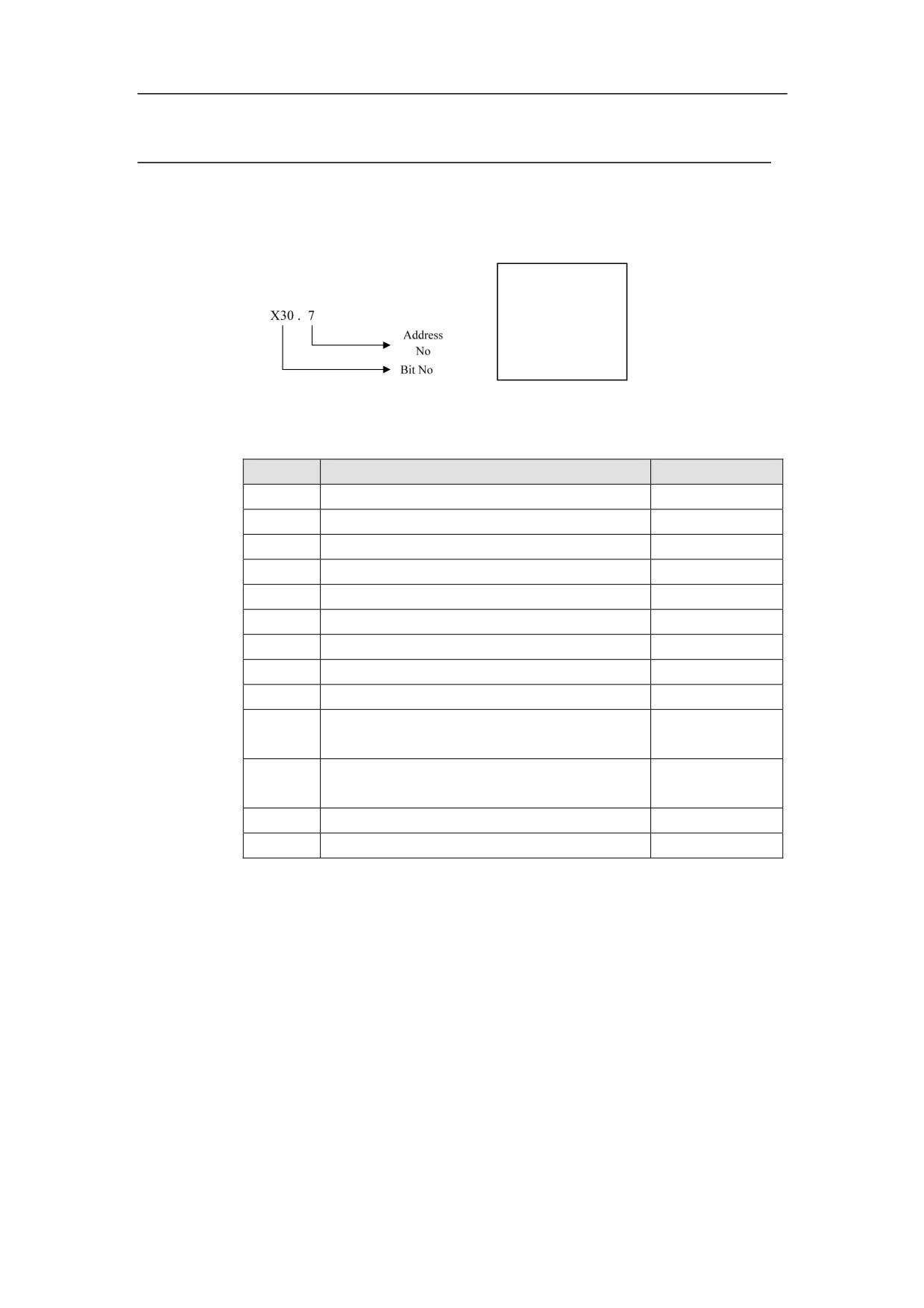
Address is used to differentiate signals. Various of addresses correspond to input
Definition
and output signals of machine and CNC, internal relay, counter and the like. The
address is composed of address No. and bit No.
Address No.
Address
format
Bit No.
A word must be specified to the left of address No., to express the signal types as
below table:
Register
Signal
Range
X
Input signal from machine
X0~~X512
Y
Signal output from PLC to machine
Y0~~Y512
F
Input signal from NC
F0~~F3119
G
Signal output from PLC to NC
G0~~G3119
R
Internal relay of single byte
R0~~R399
W
Internal relay of double-byte
W0~~W199
D
Internal relay of four-byte
D0~~D99
B
Outage hold relay
B0~~B49
P
User-defined parameter
P0~~P199
Counter(Those after C300 can be held after
C0~~C127
C
usage.)
C300~~C427
Timer
T0~~T127
T
(Those after T300 can be held after usage.)
T300~~T427
L
Label number
——
S
Subprogram number
——
14
HNC-8-PLC Programming specification
2. Basic instruction
Basic Instruction
Sequential program is mainly composed of coil, contact, symbol and function
block. The segments, by which elements of ladder diagram are jointed, form the
logical relationship of sequential program. Sequential program can be described
by ladder diagram language, as well as statement list language which is written
by mnemonics (LD, AND, OR, etc.) and register address. Ladder diagram is
written by coil contact of relay and function block.
As the international standard of IEC61131-3 lays out, ladder diagram language
and statement list language can convert each other logically, and ambiguity
caused by this can be avoided through some programming methods. In
HNC_LADDER_WIN(V1.0) editing software, you can see that the two
languages can mutually transform.
To better understand documenting and inner-making of sequential program, and
to avoid errors in logic or understanding, see the explanation of basic concepts as
following:
Type:
PLC instruction of series
8 is divided into basic instruction and function
instruction.
Basic instruction
Basic instruction is the most basic and most common part of sequential program,
with a total of 19. It executes one-bit manipulation.
Function instruction
Function instruction can perform the functions that is hard to be done by basic
elements, and it can simplify programming.
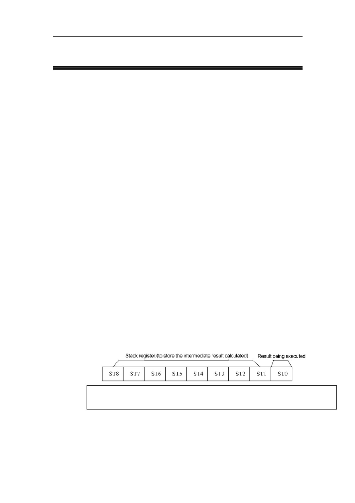
Storage of logical outcome (ST)
Stack register (to store the intermediate result calculated)
Result being executed
Storage of logical outcome is a stack-like structure. Result of the current
instruction is saved in ST0. When reading instruction such as LD and LDI
appears, result of current instruction is needed to be saved in stack. When ANB
or ORB instruction is encountered, the storage makes ST1 result out stack and
15
HNC-8-PLC Programming specification
2. Basic instruction
logically calculate with result in ST0, which then is saved in ST0. Therefore,
when sequential program is documented with statement list instruction, ANB and
ORB must correspond to the input instructions after the first instruction, one to
one; otherwise, errors may occur.
Storage of multi-output logical outcome
The role of this storage is similar with that of logical outcome storage. It is to
save result of current node, and is usually used for multi-output instruction with
conditional judgements (see detailed command instruction for the usage of MPS,
MRD, MPP). What differs from storage of logical outcome is that, it permits
reading result of node without stack out of the result. Only when the embedded
use of multi-output function is needed is storage push performed. Similarly, MPS
and MPP instructions must be used correspondingly; otherwise, logical errors
may occur.
Pre and Post
Pre indicates that other elements can be connected to the front of the element,
and post indicates that other elements can be connected to the back of the
element.
Here are constraint rules about the graphics in this manual:
16
//////////////////////