HV580L Series Frequency Inverter. User Manual (Version: 3.1.14) - page 6
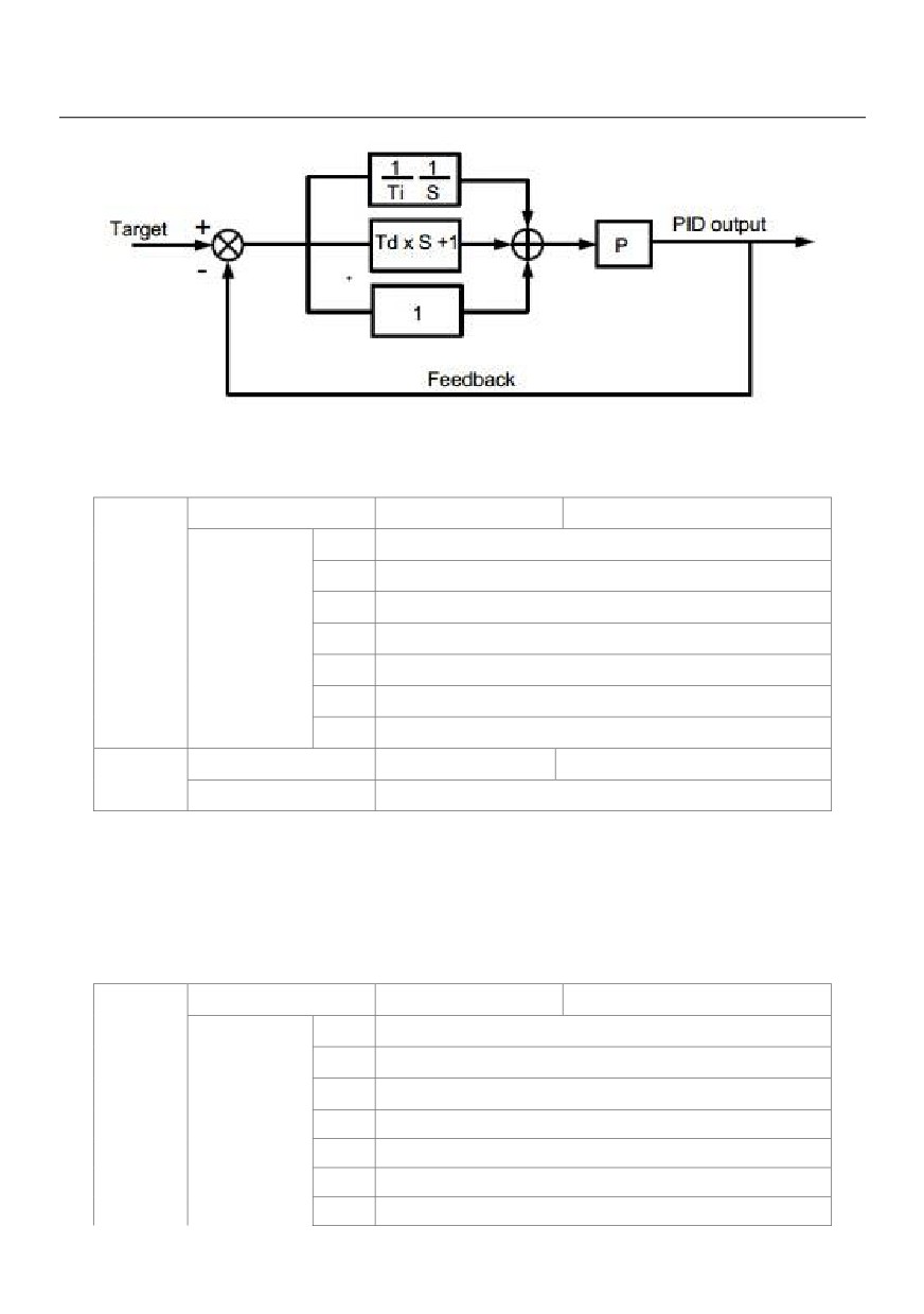
Figure 6-25 Principle block diagram of PID control
PID setting source
Default
0
0
PA-01 Setting
1
VS
2
AS
PA-00
Setting Range
3
VS2
4
PULSE Pulse (X5)
5
Communication
6
Multi-reference
PID digital setting
Default
50.0%
PA-01
Setting range
0.0% ~ 100.0%
PA-00 is used to select the channel of target process PID setting. The PID setting is a relative value and
ranges from 0.0% to 100.0%. The PID feedback is also a relative value.
The purpose of PID control is to make the PID setting and PID feedback equal.
PID Feedback source
Default
0
0
VS
1
AS
2
VS2
PA-02
Setting range
3
VS - AS
4
PULSE Pulse ( X5 )
5
Communication
6
VS+AS
155
7
MAX(|VS|,|AS|)
8
MIN (|VS|,|AS|)
This parameter is used to select the feedback signal channel of process PID.
The PID feedback is a relative value and ranges from 0.0% to 100.0%.
PID action direction
Default
0
PA-03
0
Forward action
Setting range
1
Reverse action
0: Forward action
When the feedback value is smaller than the PID setting, the AC drive's output frequency rises. For example,
the winding tension control requires forward PID action.
• 1: Reverse action
When the feedback value is smaller than the PID setting, the AC drive's output frequency reduces. For
example, the unwinding tension control requires reverse PID action.
Note that this function is influenced by the DI function 35 "Reverse PID action direction".
PID setting
Default
1000
PA-04
feedback range
Setting range
0 ~ 65535
This parameter is a non-dimensional unit. It is used for PID setting display (C-15) and PID feedback display (C-16).
Relative value 100% of PID setting feedback corresponds to the value of FA-04. If FA-04 is set to 2000 and
PID setting is 100.0%, the PID setting display (C-15) is 2000.PID
Proportional gain Kp1
Default
20.0
PA-05
Setting range
0.0 ~ 100.0
Integral time Ti1
Default
2.00s
PA-06
Setting range
0.01s ~ 10.00s
Differential timeTd1
Default
0.000s
PA-07
Setting range
0.00 ~ 10.000
PA-05 (Proportional gain Kp1)
It decides the regulating intensity of the PID regulator. The higher the Kp1 is, the larger the regulating intensity
is. The value 100.0 indicates when the deviation between PID feedback and PID setting is 100.0%, the
adjustment amplitude of the PID regulator on the output frequency reference is the maximum frequency.
• PA-06 (Integral time Ti1)
It decides the integral regulating intensity. The shorter the integral time is, the larger the regulating intensity is.
156
When the deviation between PID feedback and PID setting is 100.0%, the integral regulator performs
continuous adjustment for the time set in PA-06. Then the adjustment amplitude reaches the maximum
frequency.
• PA-07 (Differential time Td1)
It
decides the regulating intensity of the PID regulator on the deviation change. The longer
the differential time is, the larger the regulating intensity is. Differential time is the time within which the
feedback value change reaches 100.0%, and then the adjustment amplitude reaches the maximum
frequency.
Cut-off frequency of PID
Default
2.00Hz
PA-08
reverse
Setting range
0.00 ~Max frequency
In some situations, only when the PID output frequency is a negative value (AC drive reverse rotation), PID
setting and PID feedback can be equal. However, too high reverse rotation frequency is prohibited in some
applications, and FA-08 is used to determine the reverse rotation frequency upper limit.
PID deviation limit
Default
0.0%
PA-09
Setting range
0. 0% ~ 100.0%
If the deviation between PID feedback and PID setting is smaller than the value of PA-09, PID control stops.
The small deviation between PID feedback and PID setting will make the output frequency stabilize, effective
for some closed-loop control applications.
PID deviation limit
Default
0.10%
PA-10
Setting range
0.00% ~ 100.00%
It is used to set the PID differential output range. In PID control, the differential operation may easily cause
system oscillation. Thus, the PID differential regulation is restricted to a small range.
PID setting change time
Default
0.00s
PA-11
Setting range
0.00s ~ 650.00s
The PID setting change time indicates the time required for PID setting changing from 0.0% to 100.0%. The
PID setting changes linearly according to the change time, reducing the impact caused by sudden setting
change on the system.
PID feedback filter time
Default
0.00s
PA-12
Setting range
0.00s ~ 60.00s
PID output filter time
Default
0.00s
PA-13
Setting range
0.00s ~ 60.00s
PA-12 is used to filter the PID feedback, helping to reduce interference on the feedback but slowing the
157
response of the process closed-loop system.
PA-13 is used to filter the PID output frequency, helping to weaken sudden change of the AC drive output
frequency but slowing the response of the process closed-loop system.
Proportional gain Kp2
Default
20.0
PA-15
Setting range
0.0 ~ 100.0
Integral time Ti2
Default
2.00s
PA-16
Setting range
0.01s ~ 10.00s
Differential time Td2
Default
0.000s
PA-17
Setting range
0.00 ~ 10.000
PID parameter
Default
0
switchover condition
PA-18
0
No switchover
Setting range
1
Switchover via DI
2
Automatic switchover
PID parameter
Default
20.0%
PA-19
switchover deviation 1
Setting range
0.0% ~ PA-20
PID parameter
Default
80.0%
PA-20
switchover deviation 2
Setting range
PA-19 ~ 100.0%
In some applications, PID parameters switchover is required when one group of PID parameters cannot
satisfy the requirement of the whole running process.
These parameters are used for switchover between two groups of PID parameters. Regulator parameters
PA-15 to PA-17 are set in the same way as PA-05 to PA-07.
The switchover can be implemented either via a DI terminal or automatically implemented based on the
deviation.
If you select switchover via a DI terminal, the DI must be allocated with function 43 "PID parameter
switchover". If the DI is OFF, group 1 (PA-05 to PA-07) is selected. If the DI is ON, group 2 (PA-15 to PA-17) is
selected.
If you select automatic switchover, when the absolute value of the deviation between PID feedback and PID
setting is smaller than the value of PA-19, group 1 is selected. When the absolute value of the deviation
between PID feedback and PID setting is higher than the value of PA-20, group 2 is selected. When the
deviation is between PA-19 and PA-20, the PID parameters are the linear interpolated value of the two groups
of parameter values.
158
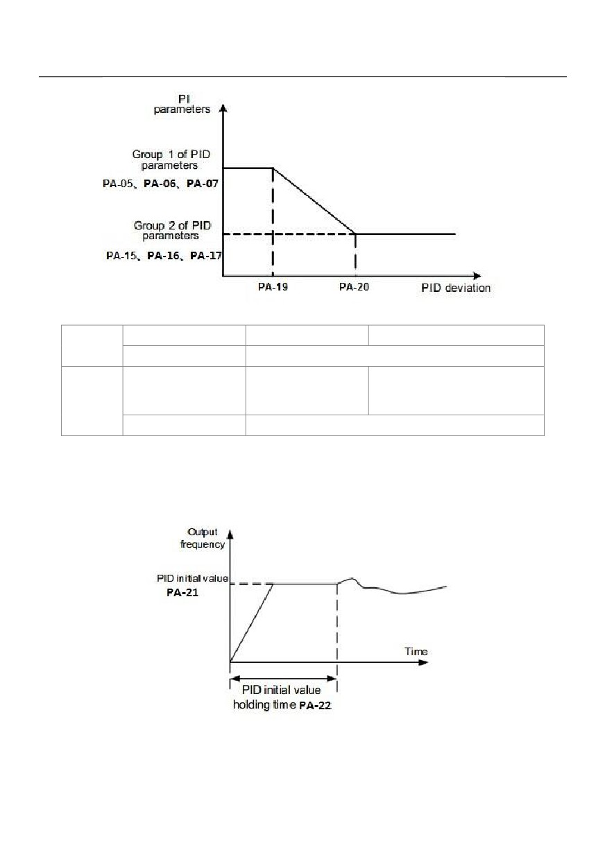
Figure 6-26 PID parameters switchover
PID initial value
Default
0.0%
PA-21
Setting range
0.0% ~ 100.0%
PID initial value holding
Default
0.00s
PA-22
time
Setting range
0.00s ~ 650.00s
When the AC drive starts up, the PID starts closed-loop algorithm only after the PID output
is fixed to the PID initial value (PA-21) and lasts the time set in PA-22.
Figure 6-27 PID initial value function
159
Maximum deviation between
Default
1.00%
two PID outputs in forward
PA-23
direction
Setting range
0.00% ~ 100.00%
Maximum deviation between
Default
1.00%
two PID outputs in reverse
PA-24
direction
Setting range
0.00% ~ 100.00%
This function is used to limit the deviation between two PID outputs (2 ms per PID output) to suppress the
rapid change of PID output and stabilize the running of the AC drive.
PA-23 and PA-24 respectively correspond to the maximum absolute value of the output deviation in forward
direction and in reverse direction.
PID integral property
Default
00
Unit's
Integral separated
digit
0
Invalid
PA-25
1
Valid
Setting range
Ten's
Whether to stop integral
digit
operation when the output reaches the limit
0
Continue integral operation
1
Stop integral operation
• Integral separated
If it is set to valid, , the PID integral operation stops when the DI allocated with function 38 "PID integral pause"
is ON In this case, only proportional and differential operations take effect.
If it is set to invalid, integral separated remains invalid no matter whether the DI allocated with function 38 "PID
integral pause" is ON or not.
• Whether to stop integral operation when the output reaches the limit
If "Stop integral operation" is selected, the PID integral operation stops, which may help to reduce the PID
overshoot.
Detection value of PID
Default
0.0%
PA-26
feedback loss
Setting range
0.0%: Not judging feedback loss; 0.1% ~ 100.0%
160
Detection time of PID
Default
0.0s
PA-27
feedback loss
Setting range
0.0s ~ 20.0s
These parameters are used to judge whether PID feedback is lost.
If the PID feedback is smaller than the value of PA-26 and the lasting time exceeds the value of PA-27, the AC
drive reports Err31 and acts according to the selected fault protection action.
PID operation at stop
Default
0
PA-28
0
No PID operation at stop
Setting range
1
PID operation at stop
It is used to select whether to continue PID operation in the state of stop. Generally, the PID operation stops
when the AC drive stops.
Group PB: Swing Frequency, Fixed Length and Count
The swing frequency function is applied to the textile and chemical fiber fields and the applications where
traversing and winding functions are required.
The swing frequency function indicates that the output frequency of the AC drive swings up and down with the
set frequency as the center. The trace of running frequency at the time axis is shown in the following figure.
The swing amplitude is set in PB-00 and PB-01. When PB-01 is set to 0, the swing amplitude is 0 and the
swing frequency does not take effect.
161
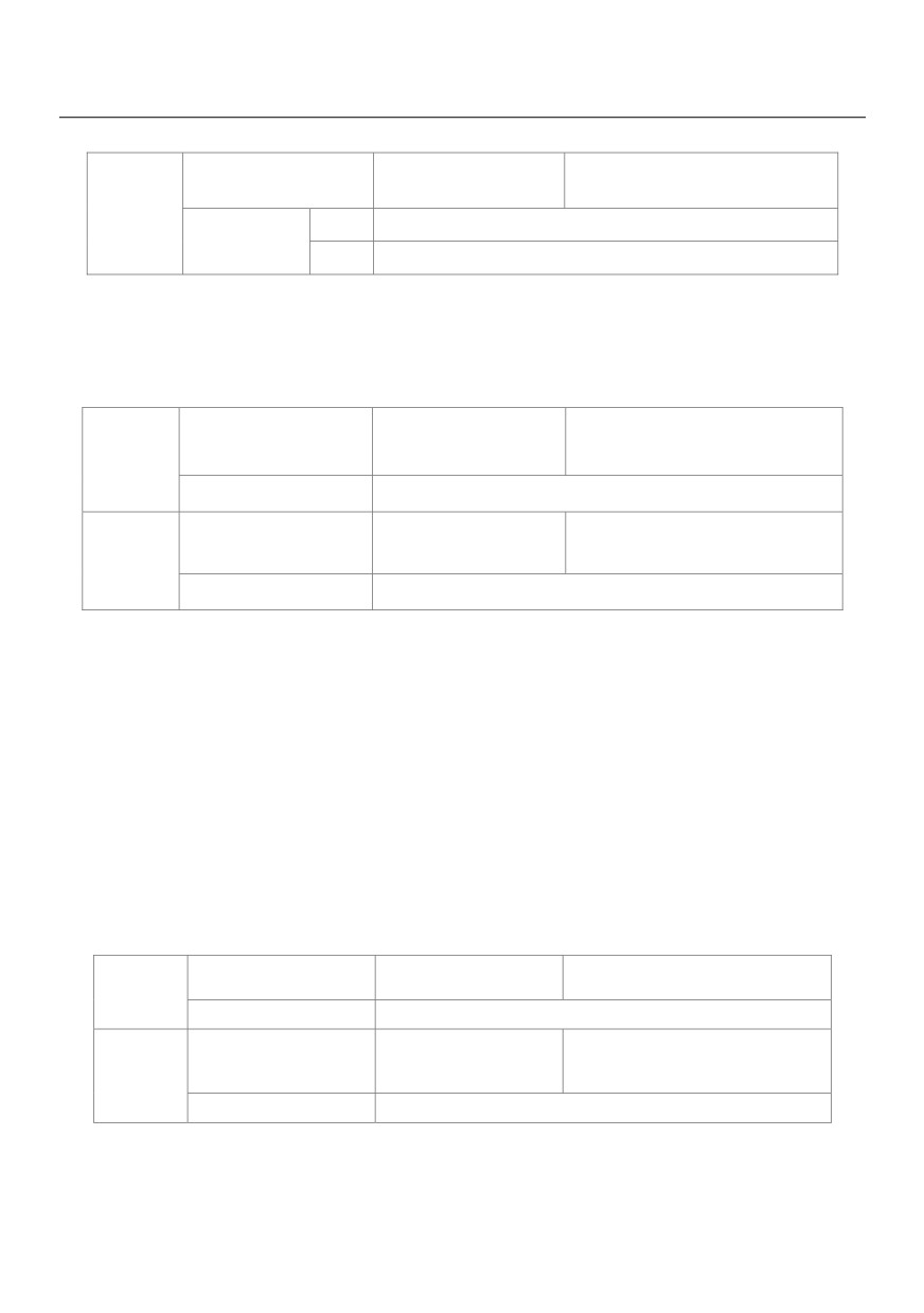
Figure 6-28 Swing frequency control
Swing frequency
Default
0
setting mode
PB-00
0
Relative to the central frequency
Setting range
1
Relative to the maximum frequency
This parameter is used to select the base value of the swing amplitude.
• 0: Relative to the central frequency (P0-07 frequency source selection)
It is variable swing amplitude system. The swing amplitude varies with the central frequency (set frequency).
• 1: Relative to the maximum frequency (P0-10 maximum output frequency)
It is fixed swing amplitude system. The swing amplitude is fixed.
Swing frequency
Default
0.0%
PB-01
amplitude
Setting range
0.0% ~ 100.0%
Jump frequency
Default
0.0%
PB-02
amplitude
Setting range
0.0% ~ 50.0%
This parameter is used to determine the swing amplitude and jump frequency amplitude.
The swing frequency is limited by the frequency upper limit and frequency lower limit.
• If relative to the central frequency (PB-00 = 0), the actual swing amplitude AW is the calculation result of
P0-07 (Frequency source selection) multiplied by PB-01.
• If relative to the maximum frequency (PB-00 = 1), the actual swing amplitude AW is the calculation result of
P0-10 (Maximum frequency) multiplied by PB-01.
Jump frequency = Swing amplitude AW x PB-02 (Jump frequency amplitude).
• If relative to the central frequency (PB-00 = 0), the jump frequency is a variable value.
• If relative to the maximum frequency (PB-00 = 1), the jump frequency is a fixed value.
The swing frequency is limited by the frequency upper limit and frequency lower limit.
Swing frequency cycle
Default
10.0s
PB-03
Setting range
0.0s ~ 3000.0s
Triangular wave rising
Default
50.0%
PB-04
time coefficient
Setting range
0.0% ~ 100.0%
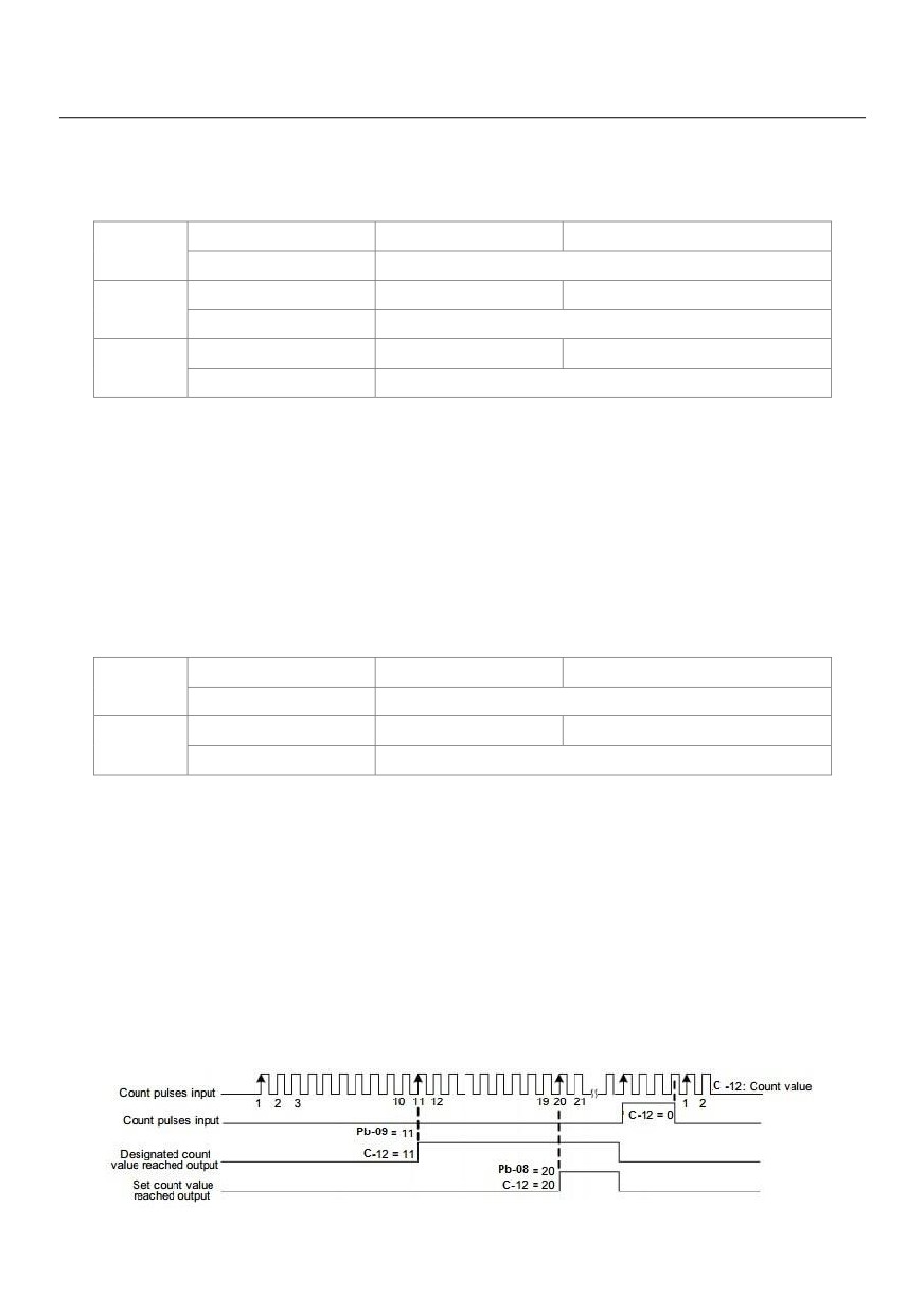
PB-03 specifies the time of a complete swing frequency cycle.
PB-04 specifies the time percentage of triangular wave rising time to PB-03 (Swing frequency cycle).
• Triangular wave rising time = PB-03 (Swing frequency cycle) x PB-04 (Triangular wave rising time coefficient,
162
unit: s)
• Triangular wave falling time = PB-03 (Swing frequency cycle) x (1 - PB-04 Triangular wave rising time
coefficient, unit: s)
Setting Length
Default
1000m
PB-05
Setting range
0m ~ 65535m
Actual Length
Default
0m
PB-06
Setting range
0m ~ 65535m
Pulse/meter
Default
100.0
PB-07
Setting range
0.1 ~ 6553.5
The preceding parameters are used for fixed length control.
The length information is collected by DI terminals. PB-06 (Actual length) is calculated by dividing the number
of pulses collected by the DI terminal by PB-07 (Number of pulses each meter).
When the actual length PB-06 exceeds the set length in PB-05, the DO terminal allocated with function 10
(Length reached) becomes ON.
During the fixed length control, the length reset operation can be performed via the DI terminal allocated with
function 28. For details, see the descriptions of P4-00 to P4-09.
Allocate corresponding DI terminal with function 27 (Length count input) in applications. If the pulse frequency
is high, X5 must be used.
Set count value
Default
1000
PB-08
Setting range
1 ~ 65535
Designated count value
Default
1000
PB-09
Setting range
1 ~ 65535
The count value needs to be collected by DI terminal. Allocate the corresponding DI terminal with function 25
(Counter input) in applications. If the pulse frequency is high, X5 must be used.
When the count value reaches the set count value (PB-08), the DO terminal allocated with function 8 (Set
count value reached) becomes ON. Then the counter stops counting.
When the counting value reaches the designated counting value (PB-09), the DO terminal allocated with
function 9 (Designated count value reached) becomes ON. Then the counter continues to count until the set
count value is reached.
PB-09 should be equal to or smaller than PB-08.
163
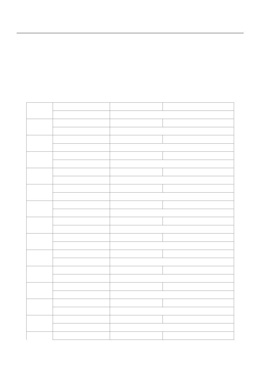
Figure 6-29 Reaching the set count value and designated count value
Group PC: Multi-Reference and Simple PLC Function
The HV580L multi-reference has many functions. Besides multi-speed, it can be used as the setting source of the
V/F separated voltage source and setting source of process PID. In addition, the multi-reference is relative value.
The simple PLC function is different from the HV580L user programmable function. Simple PLC can only
complete simple combination of multi-reference, while the user programmable function is more practical. For
details, see the descriptions of group.
Multi-reference 0
Default
0.0%
PC-00
Setting range
-100.0% ~ 100.0%
Multi-reference 1
Default
0.0%
PC-01
Setting range
-100.0% ~ 100.0%
Multi-reference 2
Default
0.0%
PC-02
Setting range
-100.0% ~ 100.0%
Multi-reference 3
Default
0.0%
PC-03
Setting range
-100.0% ~ 100.0%
Multi-reference 4
Default
0.0%
PC-04
Setting range
-100.0% ~ 100.0%
Multi-reference 5
Default
0.0%
PC-05
Setting range
-100.0% ~ 100.0%
Multi-reference 6
Default
0.0%
PC-06
Setting range
-100.0% ~ 100.0%
Multi-reference 7
Default
0.0%
PC-07
Setting range
-100.0% ~ 100.0%
UPS reference frequency
Default
0.0%
PC-08
Setting range
-100.0% ~ 100.0%
Multi-reference 9
Default
0.0%
PC-09
Setting range
-100.0% ~ 100.0%
Multi-reference 10
Default
0.0Hz
PC-10
Setting range
-100.0% ~ 100.0%
Multi-reference 11
Default
0.0%
PC-11
Setting range
-100.0% ~ 100.0%
Multi-reference 12
Default
0.0%
PC-12
Setting range
-100.0% ~ 100.0%
Multi-reference 13
Default
0.0%
PC-13
Setting range
-100.0% ~ 100.0%
PC-14
Multi-reference 14
Default
0.0%
164
Setting range
-100.0% ~ 100.0%
Multi-reference 15
Default
0.0%
PC-15
Setting range
-100.0% ~ 100.0%
Multi-reference can be the setting source of frequency, V/F separated voltage and process PID. The
multi-reference is relative value and ranges from -100.0% to 100.0%.
As frequency source, it is a percentage relative to the maximum frequency. As V/F separated voltage source,
it is a percentage relative to the rated motor voltage. As process PID setting source, it does not require
conversion.
Multi-reference can be switched over based on different states of DI terminals. For details, see the
descriptions of group P4.
Simple PLC running mode
Default
0
0
Stop after the AC drive runs one cycle
PC-16
Setting range
1
Keep final values after the AC drive runs
2
Repeat after the AC drive runs one cycle
• 0: Stop after the AC drive runs one cycle
The AC drive stops after running one cycle, and will not start up until receiving another command.
• 1: Keep final values after the AC drive runs one cycle
The AC drive keeps the final running frequency and direction after running one cycle.
• 2: Repeat after the AC drive runs one cycle
The AC drive automatically starts another cycle after running one cycle, and will not stop until receiving the
stop command.
Simple PLC can be either the frequency source or V/F separated voltage source.
When simple PLC is used as the frequency source, whether parameter values of PC-00 to PC-15 are positive
or negative determines the running direction. If the parameter values are negative, it indicates that the AC
drive runs in reverse direction.
165
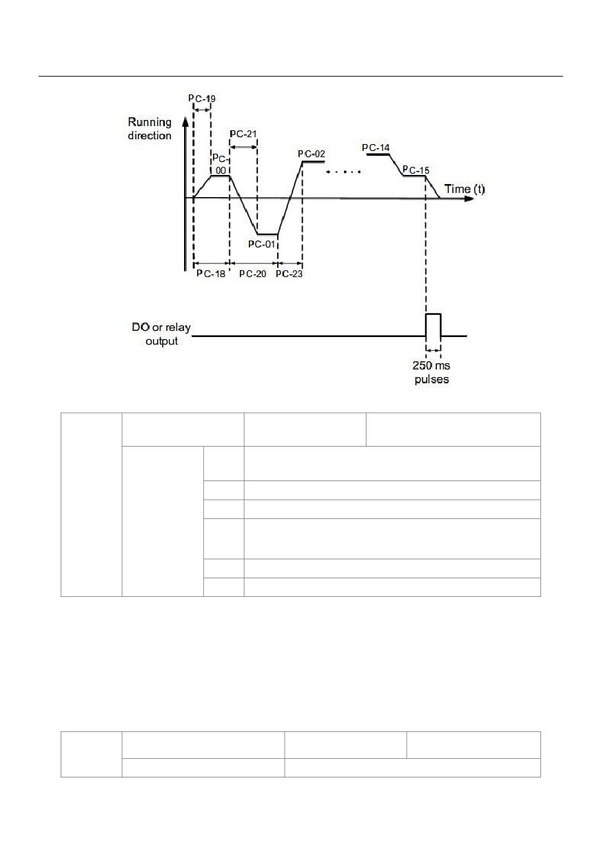
Figure 6-32 Simple PLC when used as frequency source
Simple PLC
Default
00
retentive selection
Unit's
Retentive upon power failure
digit
0
No
PC-17
1
Yes
Setting range
Ten's
Retentive upon stop
digit
0
No
1
Yes
PLC retentive upon power failure indicates that the AC drive memorizes the PLC running moment and running
frequency before power failure and will continue to run from the memorized moment after it is powered on
again. If the unit's digit is set to 0, the AC drive restarts the PLC process after it is powered on again.
PLC retentive upon stop indicates that the AC drive records the PLC running moment and running frequency
upon stop and will continue to run from the recorded moment after it starts up again. If the ten's digit is set to 0,
the AC drive restarts the PLC process after it starts up again.
Running time of simple PLC
Default
0.0s(h)
PC-18
Setting range
0.0s(h) ~ 6553.5s(h)
166
Acceleration/deceleration time of
Default
0
PC-19
simple PLC reference 0
Setting range
0 ~ 3
Running time of simple PLC
Default
0.0s(h)
PC-20
reference 1
Setting range
0.0s(h) ~ 6553.5s(h)
Acceleration/deceleration time of
Default
0
PC-21
simple PLC reference 1
Setting range
0 ~ 3
Running time of simple PLC
Default
0.0s(h)
PC-22
reference 2
Setting range
0.0s(h) ~ 6553.5s(h)
Acceleration/deceleration time of
Default
0
PC-23
simple
Setting range
0 ~ 3
Running time of simple PLC
Default
0.0s(h)
PC-24
reference 3
Setting range
0.0s(h) ~ 6553.5s(h)
Acceleration/deceleration time of
Default
0
PC-25
simple PLC reference 3
Setting range
0 ~ 3
Running time of simple PLC
Default
0.0s(h)
PC-26
reference 4
Setting range
0.0s(h) ~ 6553.5s(h)
Acceleration/deceleration time of
Default
0
PC-27
simple PLC reference 4
Setting range
0 ~ 3
Running time of simple PLC
Default
0.0s(h)
PC-28
reference 5
Setting range
0.0s(h) ~ 6553.5s(h)
Acceleration/deceleration time of
Default
0
PC-29
simple PLC reference 5
Setting range
0 ~ 3
167
Running time of simple PLC
Default
0.0s(h)
PC-30
reference 6
Setting range
0.0s(h) ~ 6553.5s(h)
Acceleration/deceleration time of
Default
0
PC-31
simple PLC reference 6
Setting range
0 ~ 3
Running time of simple PLC
Default
0.0s(h)
PC-32
reference 7
Setting range
0.0s(h) ~ 6553.5s(h)
Acceleration/deceleration time of
Default
0
PC-33
simple PLC reference 7
Setting range
0 ~ 3
Running time of simple PLC
Default
0.0s(h)
PC-34
reference 8
Setting range
0.0s(h) ~ 6553.5s(h)
Acceleration/deceleration time of
Default
0
PC-35
simple PLC reference 8
Setting range
0 ~ 3
Running time of simple PLC
Default
0.0s(h)
PC-36
reference 9
Setting range
0.0s(h) ~ 6553.5s(h)
Acceleration/deceleration time of
Default
0
PC-37
simple PLC reference 9
Setting range
0 ~ 3
Running time of simple PLC
Default
0.0s(h)
PC-38
reference 10
Setting range
0.0 s(h) ~ 6553.5s(h)
Acceleration/deceleration time of
Default
0
PC-39
simple PLC reference 10
Setting range
0 ~ 3
Running time of simple PLC
Default
0.0s(h)
PC-40
reference 11
168
Setting range
0.0s(h) ~ 6553.5s(h)
Acceleration/deceleration time of
Default
0
PC-41
simple PLC reference 11
Setting range
0 ~ 3
Running time of simple PLC
Default
0.0s(h)
PC-42
reference 12
Setting range
0.0s(h) ~ 6553.5s(h)
Acceleration/deceleration time of
Default
0
PC-43
simple PLC reference 12
Setting range
0 ~ 3
Running time of simple PLC
Default
0.0s(h)
PC-44
reference 13
Setting range
0.0s(h) ~ 6553.5s(h)
Acceleration/deceleration time of
Default
0
PC-45
simple PLC reference 13
Setting range
0 ~ 3
Running time of simple PLC
Default
0.0s(h)
PC-46
reference 14
Setting range
0.0s(h) ~ 6553.5s(h)
Acceleration/deceleration time of
Default
0
PC-47
simple PLC reference 14
Setting range
0 ~ 3
Running time of simple PLC
Default
0.0s(h)
PC-48
reference 15
Setting range
0.0s(h) ~ 6553.5s(h)
Acceleration/deceleration time of
Default
0
PC-49
simple PLC reference 15
Setting range
0 ~ 3
Time unit of simple PLC running
Default
0
PC-50
Setting range
0
S (Second)
1
H (Hours)
169
Reference 0 source
Default
0
0
Set by PC-OO
1
VS
2
AS
PC-51
Setting range
3
VS2
4
PULSE Pulse
5
PID
6
Set by preset frequency (P0-08),
It determines the setting channel of reference 0. You can perform convenient switchover between the setting
channels. When multi-reference or simple PLC is used as frequency source, the switchover between two
frequency sources can be realized easily.
Group PD: Communication parameters
Please refer to the "HV580L communication protocol".
Group PP: User’s password
User’s password
Default
0
PP-00
Setting range
0 ~ 65535
If it is set to any non-zero number, the password protection function is enabled. After a password has been set
and taken effect, you must enter the correct password in order to enter the menu. If the entered password is
incorrect you cannot view or modify parameters.
If PP-00 is set to 00000, the previously set user password is cleared, and the password protection function is
disabled.
Restore default
Default
0
0
No option
1
Restore factory settings except motor
PP-01
Setting range
2
Clear records
4
Restore user backup parameters
501
Back up current user parameters
1: Restore default settings except motor parameters
If PP-01 is set to 1, most function codes are restored to the default settings except motor parameters,
frequency reference resolution (P0-22), fault records, accumulative running time (P7-09), accumulative
power-on time (P7-13) and accumulative power consumption (P7-14).
2: Clear records
170
If PP-01 is set to 2, the fault records, accumulative running time (P7-09), accumulative power-on time (P7-13)
and accumulative power consumption P7-14) are cleared.
501: Back up current user parameters
If PP-01 is set to 501, the current parameter settings are backed up, helping you to restore the setting if
incorrect parameter setting is performed.
4: Restore user backup parameters
If PP-01 is set to 4, the previous backup user parameters are restored.
AC drive parameter
Default
11
display property
Unit's digit
Group U display selection
0
No display
PP-02
Setting
1
Display
range
Ten's digit
Group A display selection
0
No display
1
Display
Individualized parameter
Default
00
display property
Unit's digit
User-defined parameter display selection
0
No display
PP-03
1
Display
Setting
Ten's digit
User-modified parameter display selection
range
0
No display
1
Display
The setting of parameter display mode aims to facilitate you to view different types of parameters based on
actual requirements. The HV580L provides the following three parameter display modes.
Parameter Name
Description
Display function codes of the AC drive in sequence of P0 to PF,
AC drive parameter display
A0 to AF and C Group.
Display a maximum of 32 user-defined parameters included in
User-defined parameter display
group PE.
User-modified parameter display
Display the parameters that are modified.
171

If one digit of PP-03 is set to 1, you can switch over to different parameter display modes by pressing key
QUICK. By default, the AC drive parameter display mode is used.
The display codes of different parameter types are shown in the following table.
Parameter Display Mode
Display
AC drive parameter
User-defined parameter
User-modified parameter
The HV580L provides display of two types of individualized parameters: user-defined parameters and
user-modified parameters.
• You-defined parameters are included in group PE. You can add a maximum of 32 parameters, convenient
for commissioning.
In user-defined parameter mode, symbol "u" is added before the function code. For example, P1-00 is
displayed as uP1-00.
• You-modified parameters are grouped together, convenient for on-site troubleshooting.
In you-modified parameter mode, symbol "c" is added before the function code. For example, P1-00 is
displayed as cP1-00.
Parameter modification
Default
0
PP-04
0
Modifiable
Setting range
1
Not modifiable
It is used to set whether the parameters are modifiable to avoid mal-function. If it is set to 0, all parameters are
modifiable. If it is set to 1, all parameters can only be viewed.
Group A0: Torque Control and Restricting Parameters
Speed/Torque control selection
Default
0
A0-00
0
Speed control
Setting range
1
Torque Control
It is used to select the AC drive's control mode: speed control or torque control.
The HV580L provides DI terminals with two torque related functions, function 29 (Torque control prohibited)
and function 46 (Speed control/Torque control switchover). The two DI terminals need to be used together
with A0-00 to implement speed control/torque control switchover.
If the DI terminal allocated with function 46 (Speed control/Torque control switchover) is OFF, the control
mode is determined by A0-00. If the DI terminal allocated with function 46 is ON, the control mode is reverse
172
to the value of A0-00.
However, if the DI terminal with function 29 (Torque control prohibited) is ON, the AC drive is fixed to run in the
speed control mode.
Torque setting source in torque
Default
0
control
0
Digital Setting (A0-03)
1
VS
2
AS
0-01
3
VS2
Setting range
4
PULSE Pulse (X5)
5
Communication setting
6
MIN(VS,AS)
7
MAX(VS,AS)
Torque digital setting in
Default
150.0%
A0-03
torque control
Setting range
-200.0% ~ 200.0%
A0-01 is used to set the torque setting source. There are a total of eight torque setting sources.
The torque setting is a relative value. 100.0% corresponds to the AC drive's rated torque.
The setting range is -200.0% to 200.0%, indicating the AC drive's maximum torque is twice of the AC drive's
rated torque. A0-01 is used to select torque setting; there are 8 types of torque setting modes.
When torque Setting use mode1~7, communication, analog input, Pulse input100% to A0-03.
Forward maximum
Default
50.00Hz
frequency in torque
A0-05
control
Setting range
0.00Hz ~Max frequency (P0-10)
Reverse maximum
Default
50.00Hz
frequency in torque
A0-06
Setting range
0.00Hz ~Max frequency (P0-10)
Two parameters are used to set the maximum frequency in forward or reverse rotation in torque control mode.
In torque control, if the load torque is smaller than the motor output torque, the motor's rotational speed will
rise continuously. To avoid runaway of the mechanical system, the motor maximum rotating speed must be
limited in torque control.
You can implement continuous change of the maximum frequency in torque control dynamically by controlling
173
the frequency upper limit.
Acceleration time in
Default
0.00s
A0-07
torque control
Setting range
0.00s ~ 65000s
Deceleration time in
Default
0.00s
A0-08
torque control
Setting range
0.00s ~ 65000s
In torque control, the difference between the motor output torque and the load torque determines the speed
change rate of the motor and load. The motor rotational speed may change quickly and this will result in noise
or too large mechanical stress. The setting of acceleration/deceleration time in torque control makes the motor
rotational speed change softly.
However, in applications requiring rapid torque response, set the acceleration/deceleration time in torque
control to 0.00s. For example, two AC drives are connected to drive the same load. To balance the load
allocation, set one AC drive as master in speed control and the other as slave in torque control. The slave
receives the master's output torque as the torque command and must follow the master rapidly. In this case,
the acceleration/deceleration time of the slave in torque control is set to 0.0s.
Group C Monitor
C parameter set is used to monitor the inverter running state information, the customer can see through the
panel, in order to convenient for debugging, also can be read by the communication parameter set value, to be
used for PC monitor. Among them, 31 C - 00 ~ C - is the P7-03 and P7-04 defined in the operation and stop
monitoring parameters. Specific parameters function code, name and smallest unit see table 6-1
Table 6-1 C Set parameter table
Function code
Name
Smallest unit
Address
C-00
Running frequency (Hz)
0.01Hz
7000H
C-01
Set frequency (Hz)
0.01Hz
7001H
C-02
Bus voltage (V)
0.1V
7002H
C-03
Output voltage (V)
1V
7003H
C-04
Output current (A)
0.01A
7004H
174
C-05
Output power (kW)
0.1kW
7005H
C-06
Output torque (%)
0.1%
7006H
C-07
X state
1
7007H
C-08
DO state
1
7008H
C-09
VS voltage (V)
0.01V
7009H
C-10
AS voltage (V) / current (mA)
0.01V/0.01mA
700AH
C-11
VS2 voltage (V)
0.01V
700BH
C-12
Count value
1
700CH
C-13
Length value
1
700DH
C-14
Load speed
1
700EH
C-15
PID setting
1
700FH
C-16
PID feedback
1
7010H
C-17
PLC stage
1
7011H
C-18
Input pulse frequency (Hz)
0.01kHz
7012H
C-19
Feedback speed (Hz)
0.01Hz
7013H
C-20
Remaining running time
0.1Min
7014H
C-21
VS voltage before correction
0.001V
7015H
C-22
AS voltage (V) / current (mA) before correction
0.001V/0.01mA
7016H
C-23
VS2 voltage before correction
0.001V
7017H
C-24
Linear speed
1m/Min
7018H
C-25
Accumulative power-on time
1Min
7019H
C-26
Accumulative running time
0.1Min
701AH
C-27
PULSE input frequency
1Hz
701BH
C-28
Communication setting value
0.01%
701CH
C-29
Encoder feedback speed
0.01Hz
701DH
C-30
Main frequency X
0.01Hz
701EH
C-31
Auxiliary frequency Y
0.01Hz
701FH
C-32
Viewing any register address value
1
7020H
C-33
Synchronous motor rotor position
0.1°
7021H
C-34
Motor temperature
1℃
7022H
C-35
Target torque (%)
0.1%
7023H
C-36
Resolver position
1
7024H
C-37
Power factor angle
0.1°
7025H
C-38
ABZ position
1
7026H
C-39
Target voltage upon V/F separation
1V
7027H
C-40
Output voltage upon V/F separation
1V
7028H
C-41
X state visual display
1
7029H
C-42
DO state visual display
1
702AH
175
C-43
X function state visual display 1 (function 01-40)
1
702BH
C-44
X function state visual display 2 (function 41- 80)
1
702CH
C-45
Fault information
1
702DH
176
Chapter 7 Maintenance and Troubleshooting
7.1 Routine Repair and Maintenance of the HV580L
7.1.1 Routine Maintenance
The influence of the ambient temperature, humidity, dust and vibration will cause the aging of the devices in
the AC drive, which may cause potential faults or reduce the service life of the AC drive. Therefore, it is
necessary to carry out routine and periodic maintenance.
Routine maintenance involves checking:
• Whether the motor sounds abnormally during running
• Whether the motor vibrates excessively during running
• Whether the installation environment of the AC drive changes.
• Whether the AC drive's cooling fan works normally
• Whether the AC drive overheats
Routine cleaning involves:
• Keep the AC drive clean all the time.
• Remove the dust, especially metal powder on the surface of the AC drive, to prevent the dust from entering
the AC drive.
• Clear the oil stain on the cooling fan of the AC drive.
7.1.2 Periodic Inspection
Perform periodic inspection in places where inspection is difficult.
Periodic inspection involves:
Check and clean the air duct periodically.
Check whether the screws become loose.
Check whether the AC drive is corroded.
Check whether the wiring terminals show signs of arcing;
Main circuit insulation test
Prompt: Before measuring the insulating resistance with mega meter (500 VDC mega meter recommended),
disconnect the main circuit from the AC drive. Do not use the insulating resistance meter to test the insulation
177
of the control circuit. The high voltage test need not be performed again because it has been completed before
delivery.
7.1.3 Replacement of Vulnerable Components
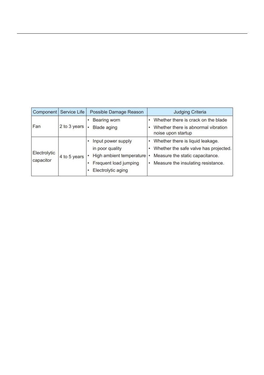
The vulnerable components of the AC drive are cooling fan and filter electrolytic capacitor.
Their service life is related to the operating environment and maintenance status. Generally, the service life is
shown as follows:
7.1.4 Storage of the AC Drive
For storage of the AC drive, pay attention to the following two aspects:
1) Pack the AC drive with the original packing box provided by HNC Electric.
2) Long-term storage degrades the electrolytic capacitor. Thus, the AC drive must be energized once every
2 years, each time lasting at least 5 hours. The input voltage must be increased slowly to the rated value with
the regulator.
7.2 Warranty Agreement
1) Free warranty only applies to the AC drive itself.
2) HNC Electric will provide 18-month warranty (starting from the leave-factory date as indicated on the
barcode) for the failure or damage under normal use conditions. If the equipment has been used for over 18
months, reasonable repair expenses will be charged.
3) Reasonable repair expenses will be charged for the damages due to the following causes:
• Improper operation without following the instructions
• Fire, flood or abnormal voltage.
• Using the AC drive for non-recommended function
178
4) The maintenance fee is charged according to HNC Electric's uniform standard. If there is an agreement, the
agreement prevails.
7.3 Faults and Solutions
The HV580L provides a total of 24 pieces of fault information and protective functions. After a fault occurs, the
AC drive implements the protection function, and displays the fault code on the operation panel (if the
operation panel is available).
Before contacting HNC Electric for technical support, you can first determine the fault type, analyze the
causes, and perform troubleshooting according to the following tables. If the fault cannot be rectified, contact
the agent or HNC Electric.
Err22 is the AC drive hardware overcurrent or overvoltage signal. In most situations, hardware overvoltage
fault causes Err22.
Table 7-1: Solutions to the faults of the HV580L
Fault Name
Display
Possible Causes
Solutions
179

1: The output circuit is grounded or short
1: Eliminate external faults.
circuited.
2: Install a reactor or an output filter.
2: The connecting cable of the motor is too long.
3: Check the air filter and the
Inverter unit
Err01
3: The module overheats.
cooling fan.
protection
4: Connect all cables properly.
4: The internal connections become loose.
5: Contact the agent or HNC
5: The main control board is faulty.
Electric.
6: The drive board is faulty.
1: The output circuit is grounded or short
1: Eliminate external faults.
circuited.
2: Perform the motor auto-tuning.
2: Motor auto-tuning is not performed.
3: Increase the acceleration time.
3: The acceleration time is too short.
4: Adjust the manual torque boost
4: Manual torque boost or V/F curve is not
or V/F curve.
appropriate.
5: Adjust the voltage to normal
Overcurrent during
Err02
5: The voltage is too low.
range.
acceleration
6: The startup operation is performed on
6: Select rotational speed tracking
the rotating motor.
restart or start the motor after it
7: A sudden load is added during
stops.
acceleration.
7: Remove the added load.
8: The AC drive model is of too small power8: Select an AC drive of higher
class.
power class.
Fault Name
Display
Possible Causes
Solutions
180
1: The output circuit is grounded or short
1: Eliminate external faults.
circuited.
2: Perform the motor auto-tuning.
2: Motor auto-tuning is not performed.
3: Increase the deceleration time.
3: The deceleration time is too short.
Overcurrent during
4: Adjust the voltage to normal
Err03
4: The voltage is too low.
deceleration
range.
5: A sudden load is added during
deceleration.
5: Remove the added load.
6: The braking unit and braking resistor are
6: Install the braking unit and
not installed.
braking resistor.
1: The output circuit is grounded or short
1: Eliminate external faults.
circuited.
2: Perform the motor auto-tuning.
2: Motor auto-tuning is not performed.
3: Adjust the voltage to normal
Overcurrent at
3: The voltage is too low.
range.
Err04
constant speed
4: A sudden load is added during operation.4: Remove the added load.
5: The AC drive model is of too small power5: Select an AC drive of higher
class.
power class.
1: The input voltage is too high.
1: Adjust the voltage to normal range.
2: An external force drives the motor during2: Cancel the external force or
Overvoltage
acceleration.
install a braking resistor.
during
Err05
3: The acceleration time is too short.
3: Increase the acceleration time.
acceleration
4: The braking unit and braking resistor are
4: Install the braking unit and
not installed.
braking resistor.
1: Adjust the voltage to normal
1: The input voltage is too high.
range.
2: An external force drives the motor during
Overvoltage
2: Cancel the external force or
deceleration.
during
Err06
install the braking resistor.
3: The deceleration time is too short.
deceleration
3: Increase the deceleration time.
4: The braking unit and braking resistor are
4: Install the braking unit and
not installed.
braking resistor.
Fault Name
Display
Possible Causes
Solutions
181
1: Adjust the voltage to normal
1: The input voltage is too high.
Overvoltage at
range.
Err07
2: An external force drives the motor during
constant speed
2: Cancel the external force or
deceleration.
install the braking resistor.
Control power
The input voltage is not within the allowableAdjust the input voltage to the
Err08
supply fault
range.
allowable range.
1: Instantaneous power failure occurs on
the input power supply.
1: Reset the fault.
2: The AC drive's input voltage is not within
the allowable range.
2: Adjust the voltage to normal
Err09
3: The bus voltage is abnormal.
range.
Under voltage
4: The rectifier bridge and buffer resistor
3: Contact the agent or HNC
are faulty.
Electric.
5: The drive board is faulty.
6: The main control board is faulty
1: The load is too heavy or locked-rotor
1: Reduce the load and check the
occurs on the motor.
motor and mechanical condition.
AC drive overload
Err10
2: The AC drive model is of too small power2: Select an AC drive of higher
class.
power class.
1: P9-01 is set improperly.
1: Set P9-01 correctly.
2: The load is too heavy or locked-rotor
2: Reduce the load and check the
Motor overload
Err11
occurs on the motor.
motor and the mechanical condition.
3: The AC drive model is of too small power3: Select an AC drive of higher
class.
power class.
1: The three-phase power input is
abnormal.
1: Eliminate external faults.
Power input
Err12
2: The drive board is faulty.
2: Contact the agent or HNC
phase loss
3: The lightening board is faulty.
Electric.
4: The main control board is faulty.
Fault Name
Display
Possible Causes
Solutions
182
1: The cable connecting the AC drive and
1: Eliminate external faults.
the motor is faulty.
2: Check whether the motor
Power output
2: The AC drive's three-phase outputs are
Err13
three-phase winding is normal.
phase loss
unbalanced when the motor is running.
3: Contact the agent or HNC
3: The drive board is faulty.
Electric.
4: The module is faulty.
1: The ambient temperature is too high.
1: Lower the ambient temperature.
2: The air filter is blocked.
2: Clean the air filter.
3: The fan is damaged.
3: Replace the damaged fan.
Module overheat
Err14
4: The thermally sensitive resistor of the
4: Replace the damaged thermally
module is damaged.
sensitive resistor.
5: The inverter module is damaged.
5: Replace the inverter module.
External
1: External fault signal is input via DI.
Err15
Reset the operation.
equipment fault
2: External fault signal is input via virtual I/O.
1: Check the cabling of host
1: The host computer is in abnormal state.
computer.
2: The communication cable is faulty.
2: Check the communication
Communication
Err16
3: P0-28 is set improperly.
cabling.
fault
4: The communication parameters in group3: Set P0-28 correctly.
PD are set improperly.
4: Set the communication
parameters properly
1: The drive board and power supply are
1: Replace the faulty drive board or
Contactor fault
Err17
faulty.
power supply board.
2: The contactor is faulty.
2: Replace the faulty contactor.
Current detection
1: The HALL device is faulty.
1: Replace the faulty HALL device.
Err18
fault
2: The drive board is faulty.
2: Replace the faulty drive board.
Fault Name
Display
Possible Causes
Solutions
183
1: Set the motor parameters
1: The motor parameters are not set
according to the nameplate
Motor auto-tuning
Err19
according to the nameplate.
properly.
fault
2: The motor auto-tuning times out.
2: Check the cable connecting the
AC drive and the motor.
1: The encoder type is incorrect.
1: Set the encoder type correctly
2: The cable connection of the encoder is
based on the actual situation.
Encoder fault
Err20
incorrect.
2: Eliminate external faults.
3: The encoder is damaged.
3: Replace the damaged encoder.
4: The PG card is faulty.
4: Replace the faulty PG card.
EEPROM
Err21
The EEPROM chip is damaged.
Replace the main control board
read-write fault
AC drive
1: Overvoltage exists.
1: Handle based on overvoltage.
Err22
hardware fault
2: Overcurrent exists.
2: Handle based on overcurrent.
Short circuit to
Err23
The motor is short circuited to the ground.
Replace the cable or motor.
ground
Accumulative
The accumulative running time reaches theClear the record through the
Err26
running time
setting value.
parameter initialization function
1: The user-defined fault 1 signal is input
User-defined
via DI.
Err27
Reset the operation.
fault 1
2: User-defined fault 1 signal is input via
virtual I/O.
1: The user-defined fault 2 signal is input
User-defined
via DI.
Err28
Reset the operation.
fault 2
2: The user-defined fault 2 signal is input
via virtual I/O.
184
Fault Name
Display
Possible Causes
Solutions
Accumulative
The accumulative power-on time reaches
Clear the record through the
power-on time
Err29
the setting value.
parameter initialization function
reached
Check that the load is
The AC drive running current is lower than
Load becoming 0
Err30
disconnected or the setting of
P9-64.
P9-64 and P9-65 is correct.
PID feedback lost
The PID feedback is lower than the setting
Check the PID feedback signal or
Err31
during running
of PA-26.
set PA-26 to a proper value.
1: The load is too heavy or locked-rotor
1: Reduce the load and check the
Pulse-by-pulse
occurs on the motor.
motor and mechanical condition.
Err40
current limit fault
2: The AC drive model is of too small power2: Select an AC drive of higher
class.
power class.
Motor switchover
Change the selection of the motor via
Perform motor switchover after the
fault during
Err41
terminal during running of the AC drive.
AC drive stops.
running
1: Set the encoder parameters
1: The encoder parameters are set
properly.
Too large speed
incorrectly.
Err42
2: Perform the motor auto-tuning.
deviation
2: The motor auto-tuning is not performed.
3: Set P9-69 and P9-70 correctly
3: P9-69 and P9-70 are set incorrectly.
based on the actual situation.
1: The encoder parameters are set
1: Set the encoder parameters
incorrectly.
properly.
Motor over-speed
Err43
2: The motor auto-tuning is not
2: Perform the motor auto-tuning.
performed.3: P9-69 and P9-70 are set
3: Set P9-69 and P9-70 correctly
incorrectly.
based on the actual situation.
185