HV580L Series Frequency Inverter. User Manual (Version: 3.1.14) - page 4
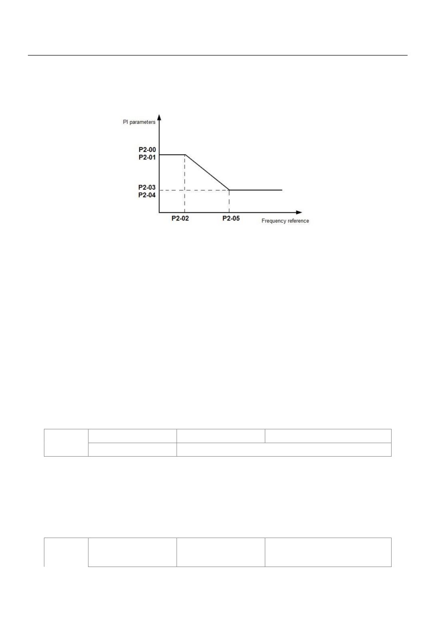
parameters are P2-03 and P2-04.
• If the running frequency is between P2-02 and P2-05, the speed loop PI parameters are obtained from the
linear switchover between the two groups of PI parameters, as shown in Figure 6-2.
Figure 6-2: Relationship between running frequencies and PI parameters
The speed dynamic response characteristics in vector control can be adjusted by setting the proportional gain
and integral time of the speed regulator.
To achieve a faster system response, increase the proportional gain and reduce the integral time. Be aware
that this may lead to system oscillation.
The recommended adjustment method is as follows:
If the factory setting cannot meet the requirements, make proper adjustment. Increase the proportional gain
first to ensure that the system does not oscillate, and then reduce the integral time to ensure that the system
has quick response and small overshoot.
Note: Improper PI parameter setting may cause too large speed overshoot, and over voltage fault may even
occur when the overshoot drops.
Vector control slip gain
Default
100%
P2-06
Setting Range
50% ~ 200%
For SFVC, it is used to adjust speed stability accuracy of the motor. When the motor with load runs at a very
low speed, increase the value of this parameter; when the motor with load runs at a very large speed,
decrease the value of this parameter.
For CLVC, it is used to adjust the output current of the AC drive with same load.
Time constant of speed
P2-07
Default
0.000s
loop filter
93
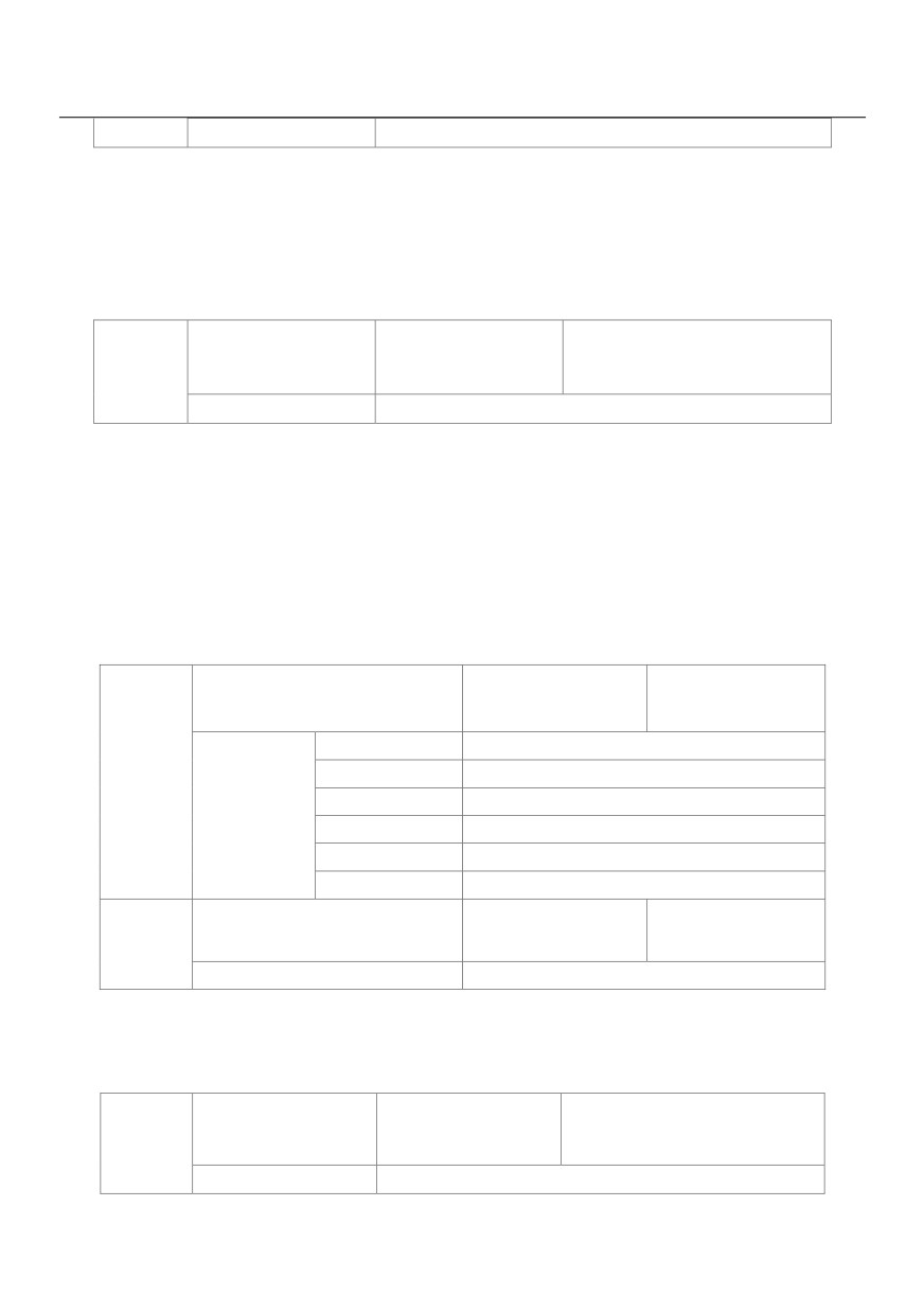
Setting Range
0.000s ~ 0.100s
In the vector control mode, the output of the speed loop regulator is torque current reference. This parameter
is used to filter the torque references. It need not be adjusted generally and can be increased in the case of
large speed fluctuation. In the case of motor oscillation, decrease the value of this parameter properly.
If the value of this parameter is small, the output torque of the AC drive may fluctuate greatly, but the response
is quick.
Vector control
Default
64
P2-08
over-excitation gain
Setting Range
0 ~ 200
During deceleration of the AC drive, over-excitation control can restrain rise of the bus voltage to avoid the
over voltage fault. The larger the over-excitation gain is, the better the restraining effect is.
Increase the over-excitation gain if the AC drive is liable to over voltage error during deceleration. Too large
over-excitation gain, however, may lead to an increase in output current. Therefore, set this parameter to a
proper value in actual applications.
Set the over-excitation gain to 0 in applications of small inertia (the bus voltage will not rise during deceleration)
or where there is a braking resistor.
Torque upper limit source in speed
Default
0
control mode
0
P2-10
P2-09
1
VS
2
AS
Setting Range
3
VS2
4
PULSE setting (X5)
5
Communication setting
Digital setting of torque upper limit in
Default
150.0%
P2-10
speed control mode
Setting Range
0.0% ~ 200.0%
In the speed control mode, the maximum output torque of the AC drive is restricted by P2-09.
If the torque upper limit is analog, pulse or communication setting, 100% of the setting corresponds to the
value of P2-10, and 100% of the value of P2-10 corresponds to the AC drive rated torque.
Excitation adjustment
Default
2000
P2-13
proportional gain
Setting Range
0 ~ 20000
94
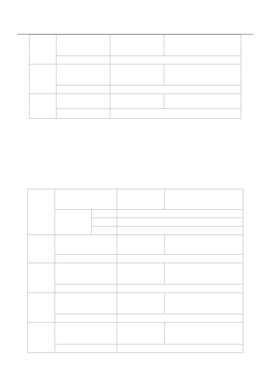
Excitation adjustment
Default
1300
P2-14
integral gain
Setting Range
0 ~ 20000
Torque adjustment
Default
2000
P2-15
proportional gain
Setting Range
0 ~ 20000
Torque adjustment
Default
1300
integral gain
P2-16
Setting Range
0 ~ 20000
These are current loop PI parameters for vector control. These parameters are automatically obtained through
"Asynchronous motor complete auto-tuning" or "Synchronous motor no-load auto-tuning", and do not need to
be modified.
The dimension of the current loop integral regulator is integral gain rather than integral time.
Note that too large current loop PI gain may lead to oscillation of the entire control loop.
Therefore, when current oscillation or torque fluctuation is great, manually decrease the proportional gain or
integral gain here.
Field weakening mode of
Default
0
synchronous motor
P2-18
0
No field weakening
Setting Range
1
Direct calculation
2
Automatic adjustment
Field weakening depth of
Default
100%
P2-19
synchronous motor
Setting Range
50% ~ 500%
Maximum field weakening
Default
50%
P2-20
current
Setting Range
1% ~ 300%
Field weakening automatic
Default
100%
P2-21
adjustment gain
Setting Range
10% ~ 500%
Field weakening integral
Default
2
P2-22
multiple
Setting Range
2 ~ 10
95
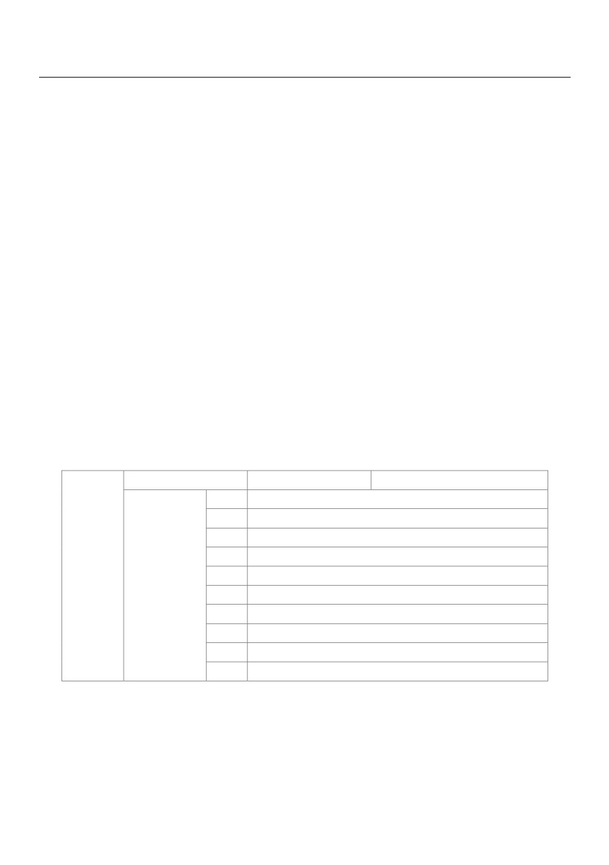
These parameters are used to set field weakening control for the synchronous motor.
If P2-18 is set to 0, field weakening control on the synchronous motor is disabled. In this case, the maximum
rotational speed is related to the AC drive bus voltage. If the motor's maximum rotational speed cannot meet
the requirements, enable the field weakening function to increase the speed.
The HV580L provides two field weakening modes: direct calculation and automatic adjustment.
• In direct calculation mode, directly calculate the demagnetized current and manually adjust the
demagnetized current by means of P2-19. The smaller the demagnetized current is, the smaller the total
output current is. However, the desired field weakening effect may not be achieved.
• In automatic adjustment mode, the best demagnetized current is selected automatically. This may influence
the system dynamic performance or cause instability.
The adjustment speed of the field weakening current can be changed by modifying the values of P2-21 and
P2-22. A very quick adjustment may cause instability. Therefore, generally do not modify them manually.
Group P3: V/F Control Parameters
Group P3 is only valid for VF control.
The VF control mode is applicable to low load applications (fan or pump) or applications where one AC drive
operates multiple motors or there is a large difference between the AC drive power and the motor power.
V/F curve setting
Default
0
0
Linear VF
1
Multi-point VF
2
Square VF
3
1.2-power VF
P3-00
4
1.4-power VF
Setting Range
6
1.6-power VF
8
1.8-power VF
9
Reserved
10
VF complete separation
11
VF half separation
0: Linear V/F. It is applicable to common constant torque load.
1: Multi-point VF. It is applicable to special load such as dehydrator and centrifuge. Any such VF curve can be
obtained by setting parameters of P3-03 to P3-08.
2: Square VF. It is applicable to centrifugal loads such as fan and pump.
3~8: VF curve between linear VF and square VF
96
10: VF complete separation. In this mode, the output frequency and output voltage of the AC drive are
independent. The output frequency is determined by the frequency source, and the output voltage is
determined by "Voltage source for VF separation" (P3-13).
It is applicable to induction heating, inverse power supply and torque motor control.
11: VF half separation
In this mode, V and F are proportional and the proportional relationship can be set in P3-13. The relationship
between V and F are also related to the rated motor voltage and rated motor frequency in Group P1.
Assume that the voltage source input is X (0 to 100%), the relationship between V and F is:
V/F = 2 x X x (Rated motor voltage) / (Rated motor frequency)
Torque boost
Default
Model dependent
P3-01
Setting Range
0.0% ~ 30%
Cut-off frequency of
Default
50.00Hz
P3-02
torque boost
Setting Range
0.00Hz ~maximum output frequency
To compensate the low frequency torque characteristics of V/F control, you can boost the output voltage of the
AC drive at low frequency by modifying P3-01. If the torque boost is set to too large, the motor may overheat,
and the AC drive may suffer over current.
If the load is large and the motor startup torque is insufficient, increase the value of P3-01.
If the load is small, decrease the value of P3-01. If it is set to 0.0, the AC drive performs automatic torque
boost. In this case, the AC drive automatically calculates the torque boost value based on motor parameters
including the stator resistance.
P3-02 specifies the frequency under which torque boost is valid. Torque boost becomes invalid when this
frequency is exceeded, as shown in the following figure 6-3.
97
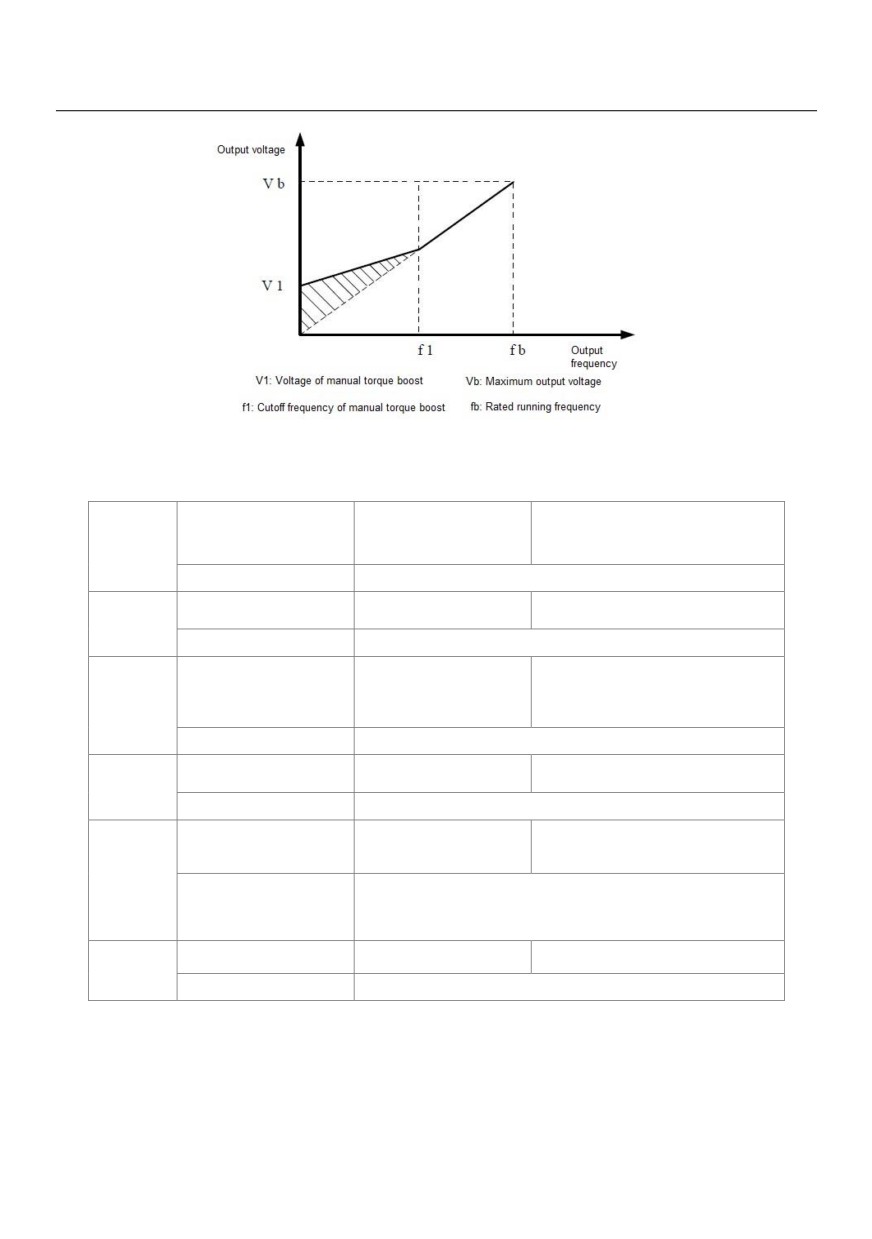
Figure 6-3 Manual torque boost
Multi-point VF frequency
Default
0.00Hz
P3-03
P1
Setting Range
0.00Hz ~ P3-05
Multi-point VF voltage V1
Default
0.0%
P3-04
Setting Range
0.0% ~ 100.0%
Multi-point VF frequency
Default
0.00Hz
P3-05
P2
Setting Range
P3-03 ~ P3-07
Multi-point VF voltage V2
Default
0.0%
P3-06
Setting Range
0.0% ~ 100.0%
Multi-point VF frequency
Default
0.00Hz
P3
P3-07
P3-05 ~rated motor frequency (P1-04)
Setting Range
Note: The rated frequencies of motors 2, 3, and 4 are
Multi-point VF voltage V3
Default
0.0%
P3-08
Setting Range
0.0% ~ 100.0%
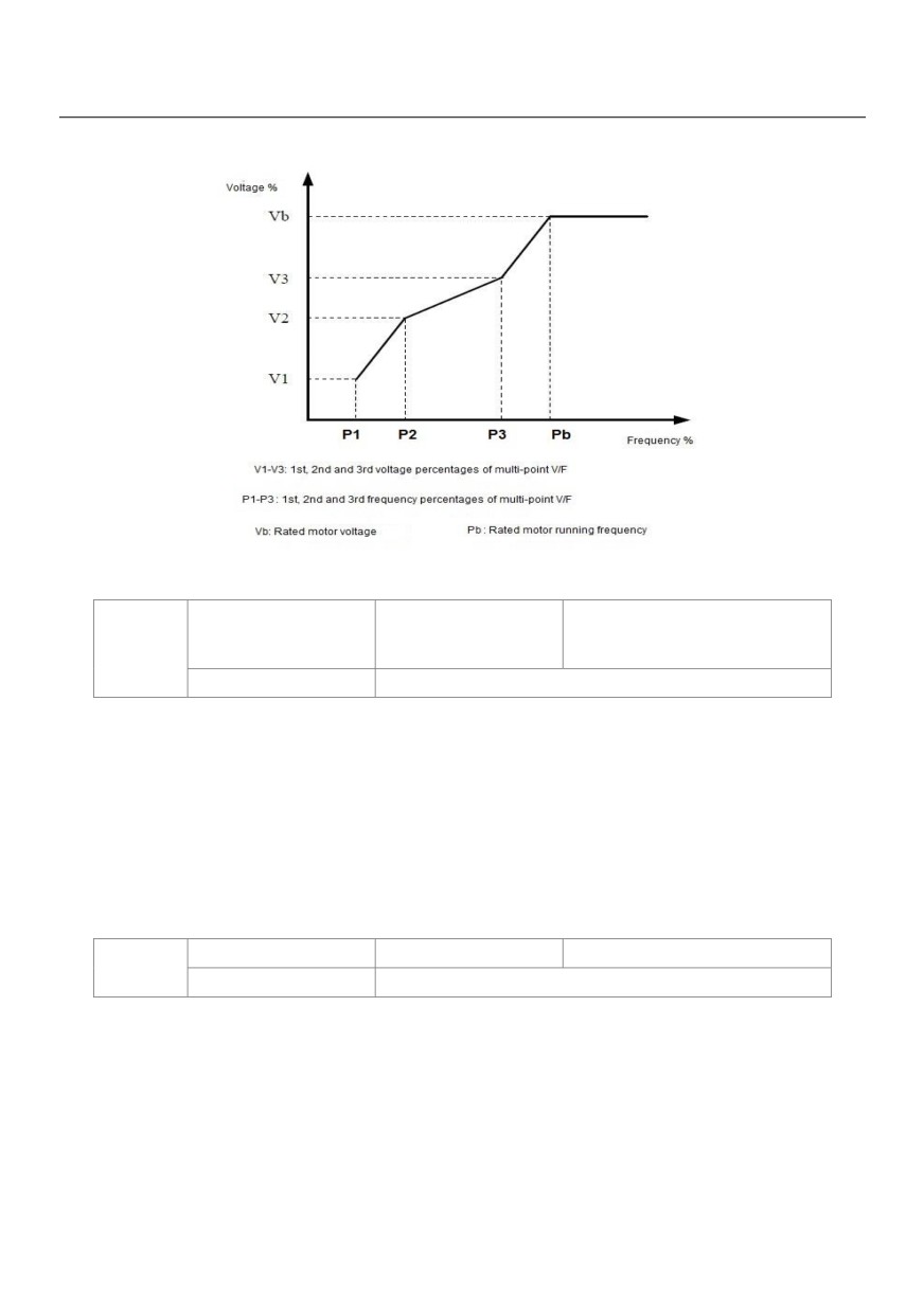
These six parameters are used to define the multi-point VF curve.
The multi-point VF curve is set based on the motor's load characteristic. The relationship between voltages
and frequencies is:
V1 < V2 < V3, P1 < P2 < P3
At low frequency, higher voltage may cause overheat or even burnt out of the motor and over current stall or
98
over current protection of the AC drive.
Figure 6-4 Setting of multi-point VF curve
VF slip compensation
Default
0.0%
P3-09
gain
Setting Range
0% ~ 200.0%
This parameter is valid only for the asynchronous motor.
It can compensate the rotational speed slip of the asynchronous motor when the load of the motor increases,
stabilizing the motor speed in case of load change.
If this parameter is set to 100%, it indicates that the compensation when the motor bears rated load is the
rated motor slip. The rated motor slip is automatically obtained by the AC drive through calculation based on
the rated motor frequency and rated motor rotational speed in group P1.
Generally, if the motor rotational speed is different from the target speed, slightly adjust this parameter.
VF over-excitation gain
Default
64
P3-10
Setting
0 ~ 200
During deceleration of the AC drive, over-excitation can restrain rise of the bus voltage, preventing the over
voltage fault. The larger the over-excitation is, the better the restraining result is.
Increase the over-excitation gain if the AC drive is liable to over voltage error during deceleration. However,
too large over-excitation gain may lead to an increase in the output current. Set P3-09 to a proper value in
actual applications.
Set the over-excitation gain to 0 in the applications where the inertia is small and the bus voltage will not rise
during motor deceleration or where there is a braking resistor.
99
VF oscillation
Default
Model dependent
P3-11
suppression gain
Setting Range
0 ~ 100
Set this parameter to a value as small as possible in the prerequisite of efficient oscillation suppression to
avoid influence on VF control.
Set this parameter to 0 if the motor has no oscillation. Increase the value properly only when the motor has
obvious oscillation. The larger the value is, the better the oscillation suppression result will be.
When the oscillation suppression function is enabled, the rated motor current and no-load current must be
correct. Otherwise, the VF oscillation suppression effect will not be satisfactory.
VF Voltage source for VF
Default
0
separation
0
Digital setting (P3-14)
1
VS
2
AS
3
VS2
P3-13
4
PULSE setting (X5)
5
Multi-reference
Setting Range
6
Simple PLC
7
PID
8
Communication setting
100.0% corresponds to the rated motor voltage (P1-02, A2-02, A3-02,
A4-02)
VF separation is generally applicable to scenarios such as induction heating, inverse power supply and motor
torque control.
If VF separated control is enabled, the output voltage can be set in P3-14 or by means of analog,
multi-reference, simple PLC, PID or communication. If you set the output voltage by means of non-digital
setting, 100% of the setting corresponds to the rated motor voltage. If a negative percentage is set, its
absolute value is used as the effective value.
0: Digital setting (P3-14)
The output voltage is set directly in P3-14.
1: VS
2: AS
3: VS2
The output voltage is set by VS terminals.
4: PULSE setting (X5)
The output voltage is set by pulses of the terminal X5.
100

Pulse setting specification: voltage range 9-30 V, frequency range 0-100 kHz
5: Multi-reference
If the voltage source is multi-reference, parameters in group P4 and PC must be set to determine the
corresponding relationship between setting signal and setting voltage.
6: Simple PLC
If the voltage source is simple PLC mode, parameters in group PC must be set to determine the setting output voltage.
7: PID
The output voltage is generated based on PID closed loop. For details, see the description of PID in group PA.
8: Communication setting
The output voltage is set by the host computer by means of communication.
When the voltage source to choose 1 ~ 8, 0 ~ 100% are corresponding to the output voltage of 0 V~ motor
rated voltage.
VF Separation of digital
Default
0V
P3-14
voltage setting
Setting Range
0V ~Motor Rated Voltage
Voltage rise time of VF
Default
0.0s
P3-15
separation
Setting Range
0.0s ~ 1000.0s
Voltage decline time of
Default
0.0s
P3-15
VF separation
Setting Range
0.0s ~ 1000.0s
The voltage source for VF separation is set in the same way as the frequency source. For details, see P0-03.
100.0% of the setting in each mode corresponds to the rated motor voltage. If the corresponding value is
negative, its absolute value is used
P3-15 indicates the time required for the output voltage to rise from 0 V to the rated motor voltage shown as t1
in the following figure.
P3-16 indicates the time required for the output voltage to decline from the rated motor voltage to 0 V, shown
as t2 in the following figure.
101
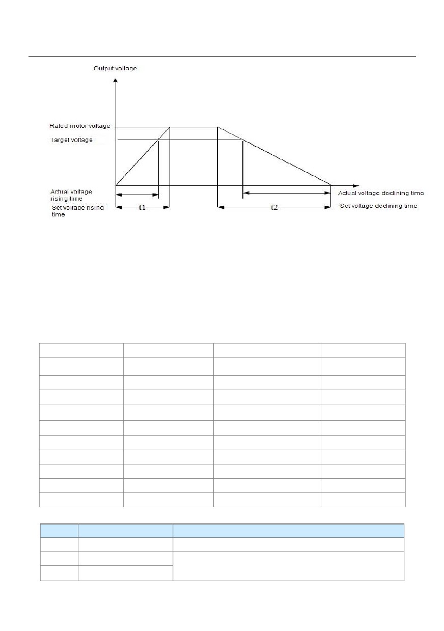
Figure 6-5 Voltage of V/F separation
Group P4: Input Terminals
The HV580L provides five DI terminals (X5 can be used for high-speed pulse input) and two analog input (AI)
terminals. The optional extension card provides another five DI terminals (X6 to X10) and an AI terminal (AI3).
Multi-function input/output expansion card has five multi-function digital input terminals (X6 ~ X10), one analog
input (VS2).
Function Code
Parameter Name
Default
Remark
P4-00
X1 function selection
1: Forward RUN (FWD)
Standard
P4-01
X2 function selection
4: Forward JOG (FJOG)
Standard
P4-02
X3 function selection
9: Fault reset (RESET)
Standard
P4-03
X4 function selection
12: Multi-reference terminal 1
Standard
P4-04
X5 function selection
13: Multi-reference terminal 2
Standard
P4-05
X6 function selection
0
Extended
P4-06
X7 function selection
0
Extended
P4-07
X8 function selection
0
Extended
P4-08
X9 function selection
0
Extended
P4-09
X10 function selection
0
Extended
The following table lists the functions available for the X terminals.
Value
Function
Description
0
No function
Set 0 for reserved terminals to avoid malfunction.
1
Forward RUN(FWD)
The terminal is used to control forward or reverse RUN of the AC
2
Reverse RUN(REV)
drive.
102
The terminal determines three-line control of the AC drive. For
3
Three-line control
details, see the description of P4-11.
4
Forward JOG(FJOG)
FJOG indicates forward JOG running, while RJOG indicates
reverse JOG running. The JOG frequency, acceleration time and
5
Reverse JOG(RJOG)
deceleration time are described respectively in P8-00, P8-01 and
P8-02.
6
Terminal UP
If the frequency is determined by external terminals, the terminals
with the two functions are used as increment and decrement
commands for frequency modification.
7
Terminal DOWN
When the frequency source is digital setting, they are used to
adjust the frequency.
In all elevator applications, an Output Contactor is installed
between the inverter output U, V, W and the motor. In an
emergency, the Safety Line is opened due to an unsafe condition
and the Output Contactor disconnects the power from the inverter
to the motor (the motor brake is also applied at the same time).
When the Output Contactor opens with current flowing through to
8
IGBT Enable
the motor (inverter IGBTs are active), there will be arcing in the
Output Contactor depending on the motor inductive energy. Arcing
of the Output Contactor can reduce the lifetime of the contactor
and in some severe cases can damage the contacts poles.
Therefore it is recommended to electronically switch off the
inverter IGBT firing circuits before opening the Output Contactor
(milliseconds later).
The terminal is used for fault reset function, the same as the
9
Fault reset (RESET)
function of RESET key on the operation panel.
Remote fault reset is implemented by this function.
The AC drive decelerates to stop, but the running parameters are
all memorized, such as PLC, swing frequency and PID
10
RUN pause
parameters. After this function is disabled, the AC drive resumes
its status before stop.
Normally open (NO) input
If this terminal becomes ON, the AC drive reports Err15 and
11
of external fault
performs the fault protection action. For more details, see the
103
description of P9-47.
Value
Function
Description
12
Multi-reference terminal 1
The setting of 16 speeds or 16 other references can be
13
Multi-reference terminal 2
implemented through combinations of 16 states of these four
14
Multi-reference terminal 3
terminals. For more details, see appendix 1.
15
Multi-reference terminal 4
Terminal 1 for
16
acceleration/deceleration
Totally four groups of acceleration/deceleration time can be
time selection
selected through combinations of two states of these two
Terminal 2 for
terminals. For more details, see appendix 2.
17
acceleration/deceleration
time selection
Frequency source
The terminal is used to perform switchover between two
18
switchover
frequency sources according to the setting in P0-07.
If the frequency source is digital setting, the terminal is used to
UP/DOWN setting clear
clear the modification by using the UP/DOWN function or the
19
(terminal, operation panel)
increment/decrement key on the operation panel, returning the set
frequency to the value of P0-08.
If the command source is set to terminal control (P0-02 = 1), this
terminal is used to perform switchover between terminal control
Command source
and operation panel control.
20
switchover terminal
If the command source is set to communication control (P0-02 =
2), this terminal is used to perform switchover between
communication control and operation panel control.
It enables the AC drive to maintain the current frequency output
Acceleration/Deceleration
21
without being affected by external signals (except the STOP
prohibited
command).
PID is invalid temporarily. The AC drive maintains the current
22
PID pause
frequency output without supporting PID adjustment of frequency
source.
104
The terminal is used to restore the original status of PLC control
23
PLC pause
for the AC drive when PLC control is started again after a pause.
24
Swing pause
The AC drive outputs the central frequency, and the swing
frequency function pauses.
25
Counter input
This terminal is used to count pulses.
26
Counter reset
This terminal is used to clear the counter status.
27
Length count input
This terminal is used to count the length.
28
Length reset
This terminal is used to clear the length.
29
Torque control prohibited
The AC drive is prohibited from torque control and enters the
speed control mode.
Pulse input (enabled only
30
X5 is used for pulse input.
for X5)
31
Reserved
Reserved
Immediate DC braking
After this terminal becomes ON, the AC drive directly switches
32
over to the DC braking state.
Normally closed (NC) inputAfter this terminal becomes ON, the AC drive reports
33
of external fault
Err15 and stops.
Frequency modification
After this terminal becomes ON, the AC drive does not respond to
34
forbidden
any frequency modification.
Reverse PID action
After this terminal becomes ON, the PID action direction is
35
direction
reversed to the direction set in PA-03.
In operation panel mode, this terminal can be used to stop the AC
36
External STOP terminal 1
drive, equivalent to the function of the STOP key on the operation
panel.
It is used to perform switchover between terminal control and
Command source
communication control. If the command source is terminal control,
37
switchover terminal 2
the system will switch over to communication control after this
terminal becomes ON.
After this terminal becomes ON, the integral adjustment function
38
PID integral pause
pauses. However, the proportional and differentiation adjustment
functions are still valid.
105
Switchover between main
After this terminal becomes ON, the frequency source X is
39
frequency source X and
replaced by the preset frequency set in P0-08.
preset frequency
Value
Function
Description
Switchover between
After this terminal is enabled, the frequency source Y is replaced
40
auxiliary frequency source
by the preset frequency set in P0-08.
Y and preset frequency
41
Motor selection terminal 1
Switchover among the four groups of motor parameters can be
implemented through the four state combinations of these two
42
Motor selection terminal 2
terminals. For more details, see appendix 3.
If the PID parameters switchover performed by means of DI
terminal (PA-18 = 1), the PID parameters are PA-05 to PA-07
43
PID parameter switchover
when the terminal becomes OFF; the PID parameters are PA-15
to PA-17 when this terminal becomes ON.
If these two terminals become ON, the AC drive reports Err27 and
44
User-defined fault 1
Err28 respectively, and performs fault protection actions based on
45
User-defined fault 2
the setting in P9-49.
This terminal enables the AC drive to switch over between speed
control and torque control. When this terminal becomes OFF, the
Speed control / Torque
46
AC drive runs in the mode set in A0-00. When this terminal
control switchover
becomes ON, the AC drive switches over to the other control
mode.
When this terminal becomes ON, the AC drive stops within the
shortest time. During the stop process, the current remains at the
47
Emergency stop
set current upper limit. This function is used to satisfy the
requirement of stopping the AC drive in emergency state.
In any control mode (operation panel, terminal or communication),
48
External STOP terminal 2
it can be used to make the AC drive decelerate to stop. In this
case, the deceleration time is deceleration time 4.
When this terminal becomes ON, the AC drive decelerates to the
49
Deceleration DC braking
initial frequency of stop DC braking and then switches over to DC
braking state.
106
When this terminal becomes ON, the AC drive's current running
Clear the current running
50
time is cleared. This function must be supported by P8-42 and
time
P8-53.
In all elevator applications, most time we will face the issue that passengers
53
UPS mode enable
may be trapped in the car if power failure suddenly happens during
use of the elevator. So the emergency evacuation mode is very important for
safety. When the elevator is in UPS mode, the drive will be auto research
Single/Two phase UPS
54
light load direction to protect passengers can be reach levelling floor for
enable
safety.
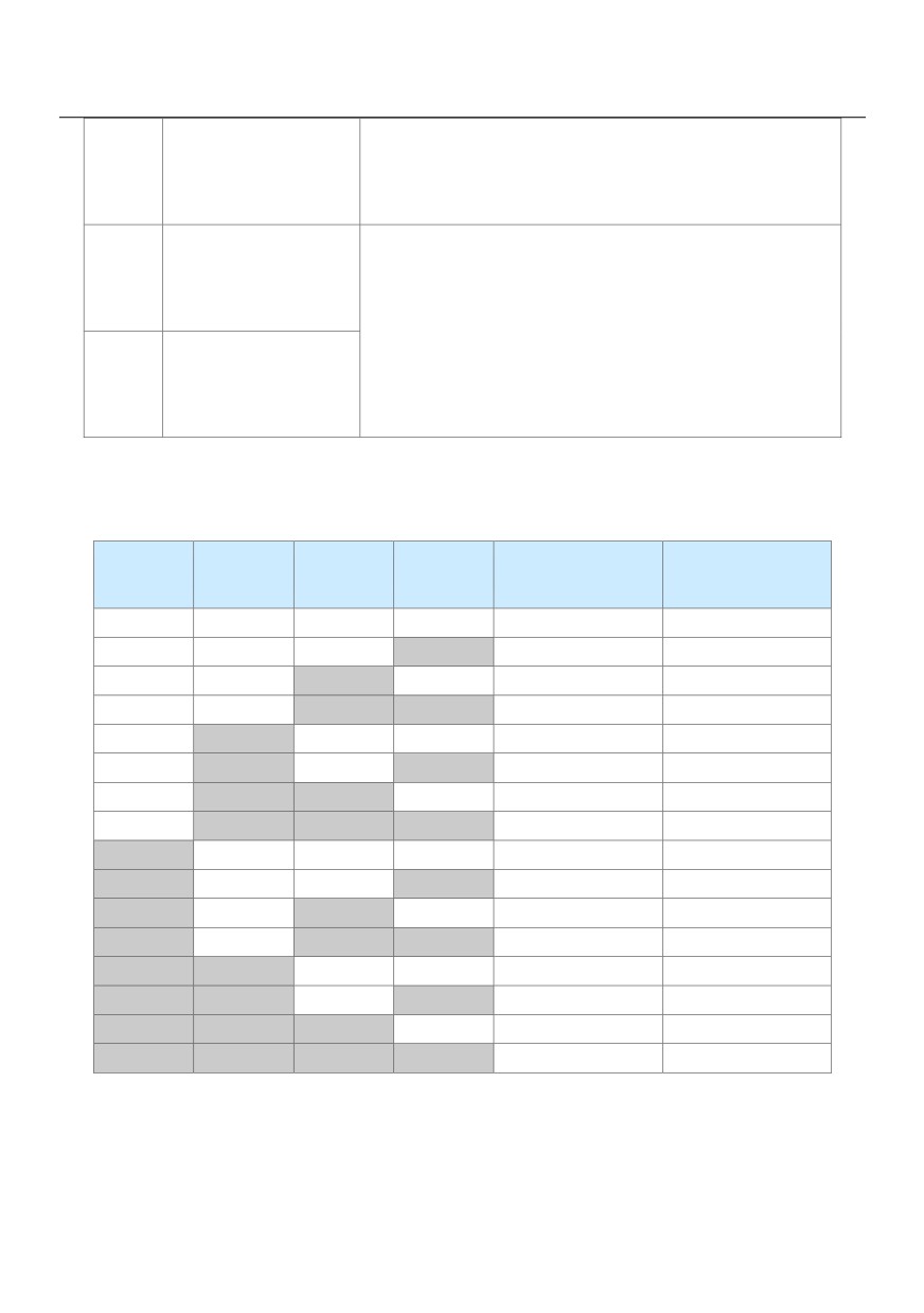
Appendix 1: State combinations of the four multi-reference terminals
The four multi-reference terminals have 16 state combinations, corresponding to 16 reference values, as listed
in the following table:
Corresponding
K4
K3
K2
K1
Reference Setting
Parameter
OFF
OFF
OFF
OFF
Reference 0
PC-00
OFF
OFF
OFF
ON
Reference 1
PC-01
OFF
OFF
ON
OFF
Reference 2
PC-02
OFF
OFF
ON
ON
Reference 3
PC-03
OFF
ON
OFF
OFF
Reference 4
PC-04
OFF
ON
OFF
ON
Reference 5
PC-05
OFF
ON
ON
OFF
Reference 6
PC-06
OFF
ON
ON
ON
Reference 7
PC-07
ON
OFF
OFF
OFF
Reference 8
PC-08
ON
OFF
OFF
ON
Reference 9
PC-09
ON
OFF
ON
OFF
Reference 10
PC-10
ON
OFF
ON
ON
Reference 11
PC-11
ON
ON
OFF
OFF
Reference 12
PC-12
ON
ON
OFF
ON
Reference 13
PC-13
ON
ON
ON
OFF
Reference 14
PC-14
ON
ON
ON
ON
Reference 15
PC-15
If the frequency source is multi-reference, the value 100% of PC-00 to PC-15 corresponds to the value of
P0-10 (Maximum frequency).
Besides the multi-speed function, the multi-reference can be also used as the PID setting source or the
voltage source for VF separation, satisfying the requirement on switchover of different setting values.
107
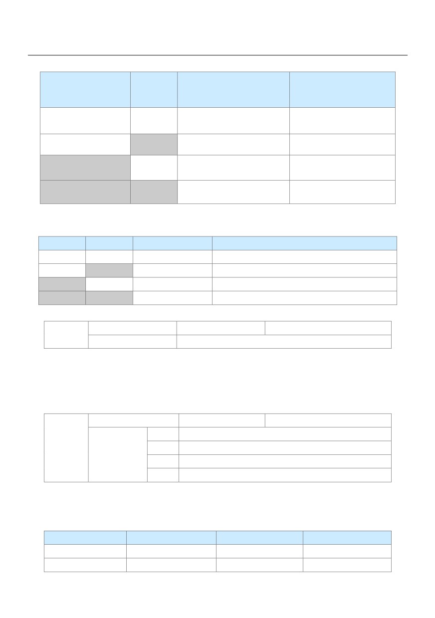
Appendix 2: State combinations of two terminals for acceleration/deceleration time selection
Acceleration/Deceleration Time
Terminal 2
Terminal 1
Corresponding Parameters
Selection
OFF
OFF
Acceleration/Deceleration time 1
P0-17、P0-18
OFF
ON
Acceleration/Deceleration time 2
P8-03、P8-04
ON
OFF
Acceleration/Deceleration time 3
P8-05、P8-06
ON
ON
Acceleration/Deceleration time 4
P8-07、P8-08
Appendix 3: State combinations of two motor selection terminals
Terminal 2
Terminal 1
Selected Motor
Corresponding Parameters
OFF
OFF
Motor 1
Group P1, P2
OFF
ON
Motor 2
Group A2
ON
OFF
Motor 3
Group A3
ON
ON
Motor 4
Group A4
X filter time
Default
0.010s
P4-10
Setting Range
0.000s ~ 1.000s
It is used to set the software filter time of X terminal status. If X terminals are liable to interference and may
cause malfunction, increase the value of this parameter to enhance the anti-interference capability. However,
increase of X filter time will reduce the response of X terminals.
Terminal command mode
Default
0
0
Two-line mode 1
P4-11
1
Two-line mode 2
Setting Range
2
Three-line mode 1
3
Three-line mode 2
This parameter is used to set the mode in which the AC drive is controlled by external terminals.
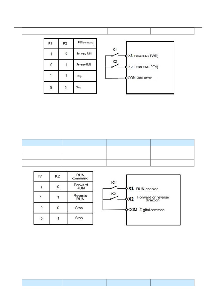
0: Two-line mode 1: It is the most commonly used two-line mode, in which the forward/reverse rotation of the
motor is decided by X1 and X2. The parameters are set as below:
Function Code
Parameter Name
Value
Function Description
P4-11
Terminal command mode
0
Two-line 1
P4-00
X1 function selection
1
Forward RUN (FWD)
108
P4-01
X2 function selection
2
Reverse RUN (REV)
Figure 6-6 Setting of two-line mode 1
1: Two-line mode 2
In this mode, X1 is RUN enabled terminal, and X2 determines the running direction.
The parameters are set as below:
Function Code
Parameter Name
Value
Function Description
P4-11
Terminal command mode1
Two-line 2
P4-00
X1 function selection
1
RUN enabled
P4-01
X2 function selection
2
Forward or reverse
Figure 6-7 Setting of two-line mode 2
As shown in the preceding figure, if K1 is ON, the AC drive instructs forward rotation when K2 is OFF, and
instructs reverse rotation when K2 is ON. If K1 is OFF, the AC drive stops.
2: Three-line mode 1
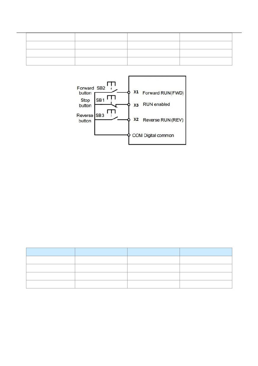
In this mode, X3 is RUN enabled terminal, and the direction is decided by X1 and X2.
The parameters are set as below:
Function Code
Parameter Name
Value
Function Description
109
P4-11
Terminal command mode2
Three-line 1
P4-00
X1 function selection
1
Forward RUN (FWD)
P4-01
X2 function selection
2
Reverse RUN (REV)
P4-02
X3 function selection
3
Three-line control
Figure 6-8 Setting of three-line mode 1
As shown in the preceding figure, if SB1 is ON, the AC drive instructs forward rotation when SB2 is pressed to
be ON and instructs reverse rotation when SB3 is pressed to be ON. The AC drive stops immediately after
SB1 becomes OFF. During normal startup and running, SB1 must remain ON. The AC drive's running state is
determined by the final actions on SB1, SB2 and SB3.
3: Three-line mode 2
In this mode, X3 is RUN enabled terminal. The RUN command is given by X1 and the direction is decided by
X2. The parameters are set as below:
Function Codes are set as below:
Function Code
Parameter Name
Value
Function Description
P4-11
Terminal command mode3
Three-line 2
P4-00
X1 function selection
1
RUN enabled
P4-01
X2 function selection
2
Forward or reverse
P4-02
X3 function selection
3
Three-line control
110
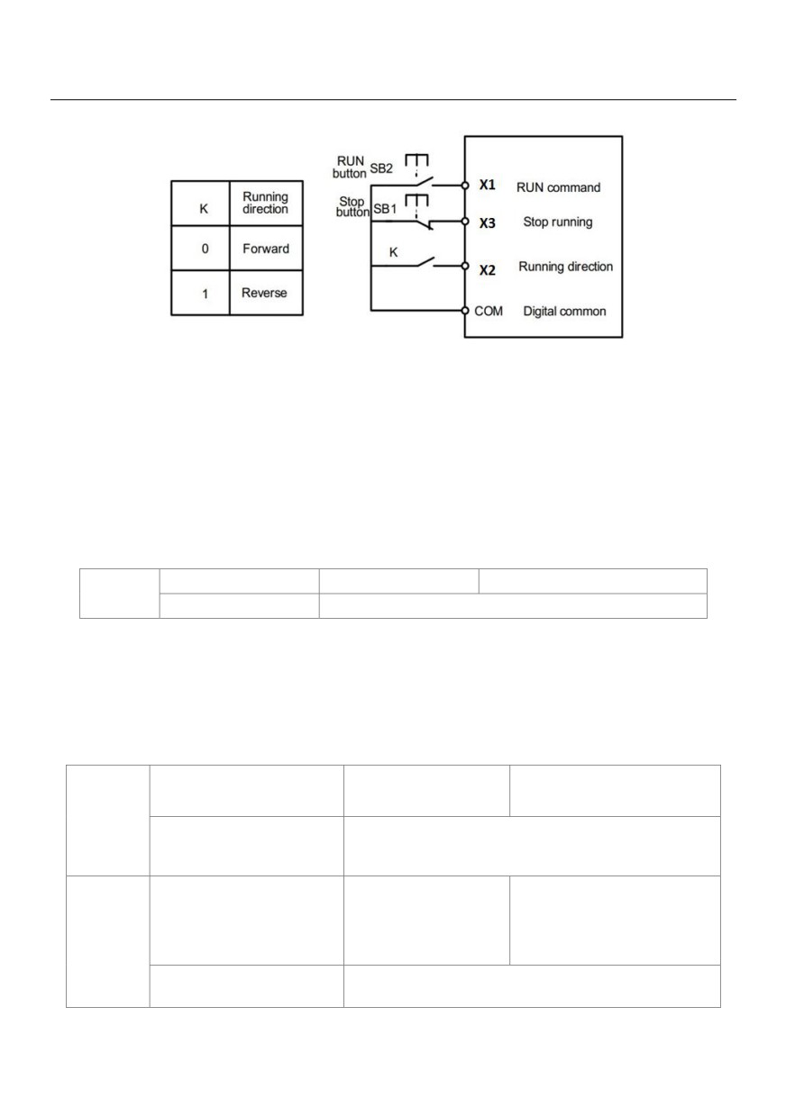
Figure 6-9 Setting of three-line mode 2
As shown in the preceding figure, if SB1 is ON, the AC drive starts running when SB2 is pressed to be ON; the
AC drive instructs forward rotation when K is OFF and instructs reverse rotation when K is ON. The AC drive
stops immediately after SB1 becomes OFF. During normal startup and running, SB1 must remain ON. The AC
drive's running state is determined by the final actions of SB1, SB2 and K.
Terminal UP/DOWN rate
Default
1.00Hz/s
P4-12
Setting Range
0.01Hz/s ~ 65.535Hz/s
It is used to adjust the rate of change of frequency when the frequency is adjusted by means of terminal
UP/DOWN.
If P0-22 (Frequency reference resolution) is 2, the setting range is 0.001-65.535 Hz/s.
If P0-22 (Frequency reference resolution) is 1, the setting range is 0.01-655.35 Hz/s.
VS curve 1 minimum input
Default
0.00V
P4-13
Setting Range
0.00V ~ P4-15
Corresponding setting of VS
curve 1 minimum input
Default
0.0%
P4-14
curve 1 minimum input
Setting Range
-100.00% ~ 100.0%
111
VS curve 1 maximum input
Default
10.00V
P4-15
Setting Range
P4-13 ~ 10.00V
Corresponding setting of VS
Default
100.0%
curve 1 maximum input
P4-16
Setting Range
-100.00% ~ 100.0%
VS1 filter time
Default
0.10s
P4-17
Setting Range
0.00s ~ 10.00s
These parameters are used to define the relationship between the analog input voltage and the corresponding
setting.
When the analog input voltage exceeds the maximum value (P4-15), the maximum value is used. When the
analog input voltage is less than the minimum value (P4-13), the value set in P4-34 (Setting for VS less than
minimum input) is used.
When the analog input is current input, 1 mA current corresponds to 0.5 V voltages.
P4-17 (VS 1 filter time) is used to set the software filter time of VS. If the analog input is liable to interference,
increase the value of this parameter to stabilize the detected analog input. However, increase of the AI filter
time will slow the response of analog detection. Set this parameter properly based on actual conditions.
In different applications, 100% of analog input corresponds to different nominal values. For details, refer to the
description of different applications.
Two typical setting examples are shown in the following figure.
112
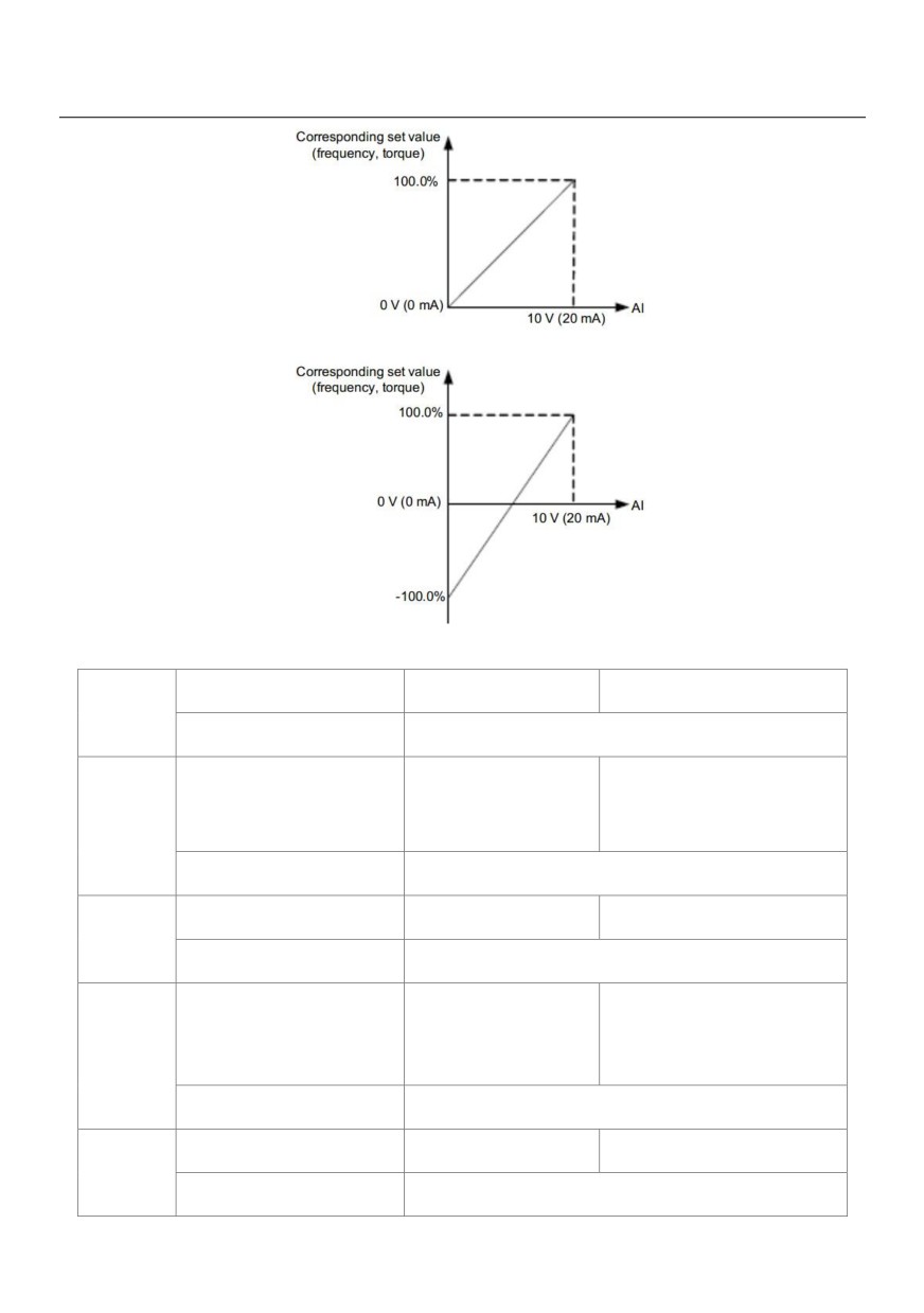
Figure 6-10 Corresponding relationship between analog input and set values
AS curve minimum input
Default
0.00V
P4-18
Setting Range
0.00V ~ P4-20
Corresponding setting of AS
Default
0.0%
P4-19
curve minimum input
Setting Range
-100.00% ~ 100.0%
AS curve maximum input
Default
10.00V
P4-20
Setting Range
P4-18 ~ 10.00V
Corresponding setting of AS
Default
100.0%
P4-21
curve maximum input
Setting Range
-100.00% ~ 100.0%
AS filter time
Default
0.10s
P4-22
Setting Range
0.00s ~ 10.00s
113
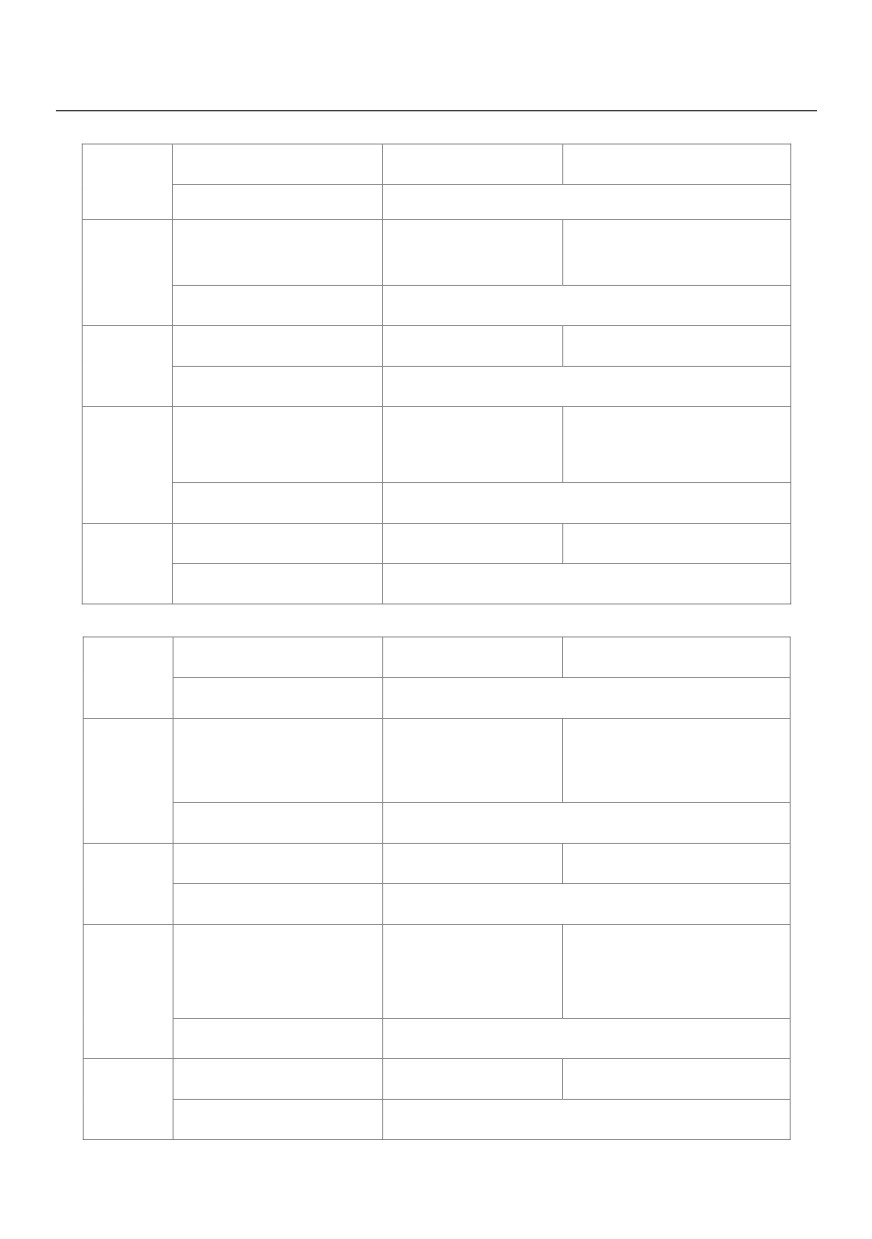
The method of setting AS functions is similar to that of setting VS1 function.
VS curve 2 minimum input
Default
0.00V
P4-23
Setting Range
0.00s ~ P4-25
Corresponding setting of VS
Default
0.0%
P4-24
curve 2 minimum input
Setting Range
-100.00% ~ 100.0%
VS curve 2 maximum input
Default
10.00V
P4-25
Setting Range
P4-23 ~ 10.00V
Corresponding setting of VS
Default
100.0%
P4-26
curve 2 maximum input
Setting Range
-100.00% ~ 100.0%
VS2 filter time
Default
0.10s
P4-27
Setting Range
0.00s ~ 10.00s
The method of setting VS 2 functions is similar to that of setting VS1 function.
PULSE minimum input
Default
0.00kHz
P4-28
Setting Range
0.00kHz ~ P4-30
Corresponding setting of
Default
0.0%
P4-29
pulse minimum input
Setting Range
-100.00% ~ 100.0%
Pulse maximum input
Default
50.00kHz
P4-30
Setting Range
P4-28 ~ 50.00kHz
Corresponding setting of
Default
100.0%
P4-31
pulse maximum input
Setting Range
-100.00% ~ 100.0%
PULSE filter time
Default
0.10s
P4-32
Setting Range
0.00s ~ 10.00s
114
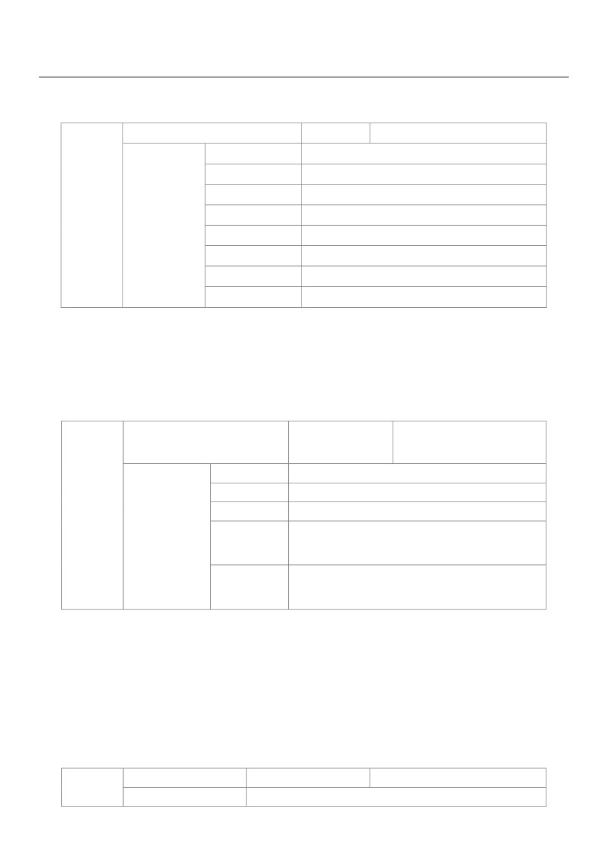
These parameters are used to set the relationship between X5 pulse input and corresponding settings. The
pulses can only be input by X5. The method of setting this function is similar to that of setting VS 1function.
VS curve selection
Default
321
Unit's digit
VS curve selection
1
Curve 1(2 points, see P4-13 ~ P4-16)
2
Curve 2(2 points, see P4-18 ~ P4-21)
P4-33
3
Curve 3(2 points, see P4-23 ~ P4-26)
Setting Range
4
Curve 4(4 points, see A6-00 ~ A6-07)
5
Curve 5(4 points, see A6-08 ~ A6-15)
Ten's digit
AS curve selection(1 ~ 5, same to VS1)
Hundred's digit
VS2 curve selection(1 ~ 5, same to VS1)
The unit's digit, ten's digit and hundred's digit of this parameter are respectively used to select the
corresponding curve of VS1, AS and VS2. Any of the five curves can be selected for VS1, AS and VS2.
Curve 1, curve 2 and curve 3 are all 2-point curves, set in group P4. Curve 4 and curve 5 are both 4-point
curves, set in group A6.
The HV580L provides two AI terminals as standard. VS2 is provided by an optional extension card.
Setting for VS less than minimum
Default
000
input
Unit's digit
Setting for VS1 less than minimum input
0
Minimum value
P4-34
1
0.0%
Setting for AS less than minimum input
Setting Range
Ten's digit
(0 ~ 1,same to VS1)
Setting for VS2 less than minimum input
Hundred's digit
(0 ~ 1,same to VS1)
This parameter is used to determine the corresponding setting when the analog input voltage is less than the
minimum value. The unit's digit, ten's digit and hundred's digit of this parameter respectively correspond to the
setting for VS2, AS and VS2.
If the value of a certain digit is 0, when analog input voltage is less than the minimum input, the corresponding
setting of the minimum input (P4-14, P4-19, P4-24) is used.
If the value of a certain digit is 1, when analog input voltage is less than the minimum input, the corresponding
value of this analog input is 0.0%.
X1 delay time
Default
0.0s
P4-35
Setting Range
0.0s ~ 3600.0s
115
X2 delay time
Default
0.0s
P4-36
Setting Range
0.0s ~ 3600.0s
X3 delay time
Default
0.0s
P4-37
Setting Range
0.0s ~ 3600.0s
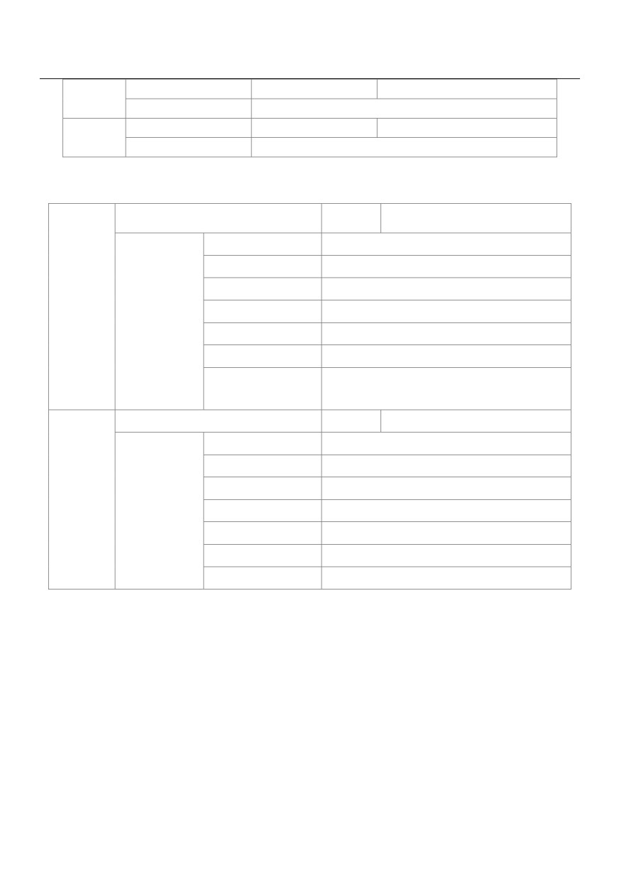
These parameters are used to set the delay time of the AC drive when the status of X terminals changes.
Currently, only X1, X2 and X3 support the delay time function.
X valid mode selection 1
Default
00000
Unit's digit
X1 valid mode
0
High level valid
1
Low level valid
P4-38
Ten's digit
X2 valid mode (0 ~ 1, same as X1)
Setting Range
Hundred's digit
X3 valid mode (0 ~ 1, same as X1)
Thousand's digit
X4 valid mode (0 ~ 1, same as X1)
Ten thousand's digit
X5 valid mode (0 ~ 1, same as X1)
X valid mode selection 2
Default
00000
Unit's digit
X6 valid mode
0
High level valid
1
Low level valid
P4-39
Setting Range
Ten's digit
X7 valid mode (0 ~ 1, same as X1)
Hundred's digit
X8 valid mode (0 ~ 1, same as X1)
Thousand's digit
X9 valid mode (0 ~ 1, same as X1)
Ten thousand's digit
X10 valid mode (0 ~ 1, same as X1)
These parameters are used to set the valid mode of DI terminals.
0: High level valid
The X terminal is valid when being connected with COM, and invalid when being disconnected from COM.
1: Low level valid
The DI terminal is invalid when being connected with COM, and valid when being disconnected from COM.
Group P5: Output Terminals
The HV580L provides an analog output (AO) terminal, a digital output (DO) terminal, a relay terminal and a FM
terminal (used for high-speed pulse output or open-collector switch signal output) as standard. If these output
terminals cannot satisfy requirements, use an optional I/O extension card that provides an AO terminal (AO2),
a relay terminal (relay 2) and a DO terminal (Y2).
116
Y2 terminal output mode
Default
0
P5-00
0
Pulse output (Y2P)
Setting Range
1
Switch signal output (Y2R)
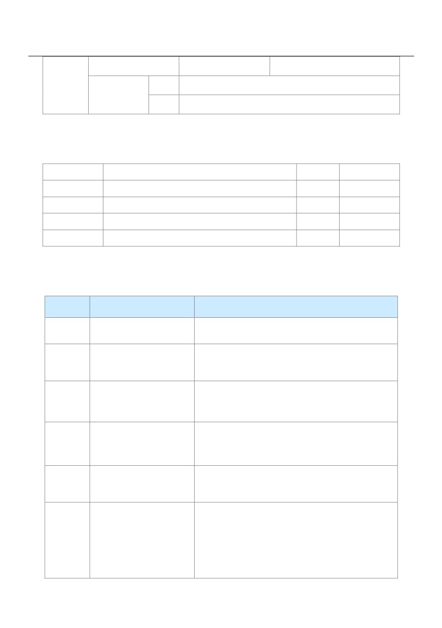
The Y2 terminal is programmable multiplexing terminal. It can be used for high-speed pulse output (Y2P), with
maximum frequency of 100 kHz. Refer to P5-06 for relevant functions of Y2P. It can also be used as open
collector switch signal output (Y2R).
P5-01
Y2R function (open-collector output terminal)
Default
0
P5-02
Relay function (T/A-T/B-T/C)
Default
2
P5-03
Extension card relay function (P/A-P/B-P/C)
Default
0
P5-04
Y1 function selection (open-collector output terminal)
Default
1
P5-05
Extension card Y2 function
Default
4
These five parameters are used to select the functions of the five digital output terminals. T/A-T/B-T/C and
P/A-P/B-P/C are respectively the relays on the control board and the extension card.
The functions of the output terminals are described in the following table.
Value
Function
Description
0
No output
The terminal has no function.
When the AC drive is running and has output frequency
1
AC drive running
(can be zero), the terminal becomes ON.
When the AC drive stops due to a fault, the terminal
2
Fault output (stop)
becomes ON.
Frequency-level detection
3
Refer to the descriptions of P8-19 and P8-20.
FDT1 output
4
Frequency reached
Refer to the descriptions of P8-21.
If the AC drive runs with the output frequency of 0, the
Zero-speed running
5
terminal becomes ON. If the AC drive is in the stop state,
(no output at stop)
the terminal becomes OFF.
117
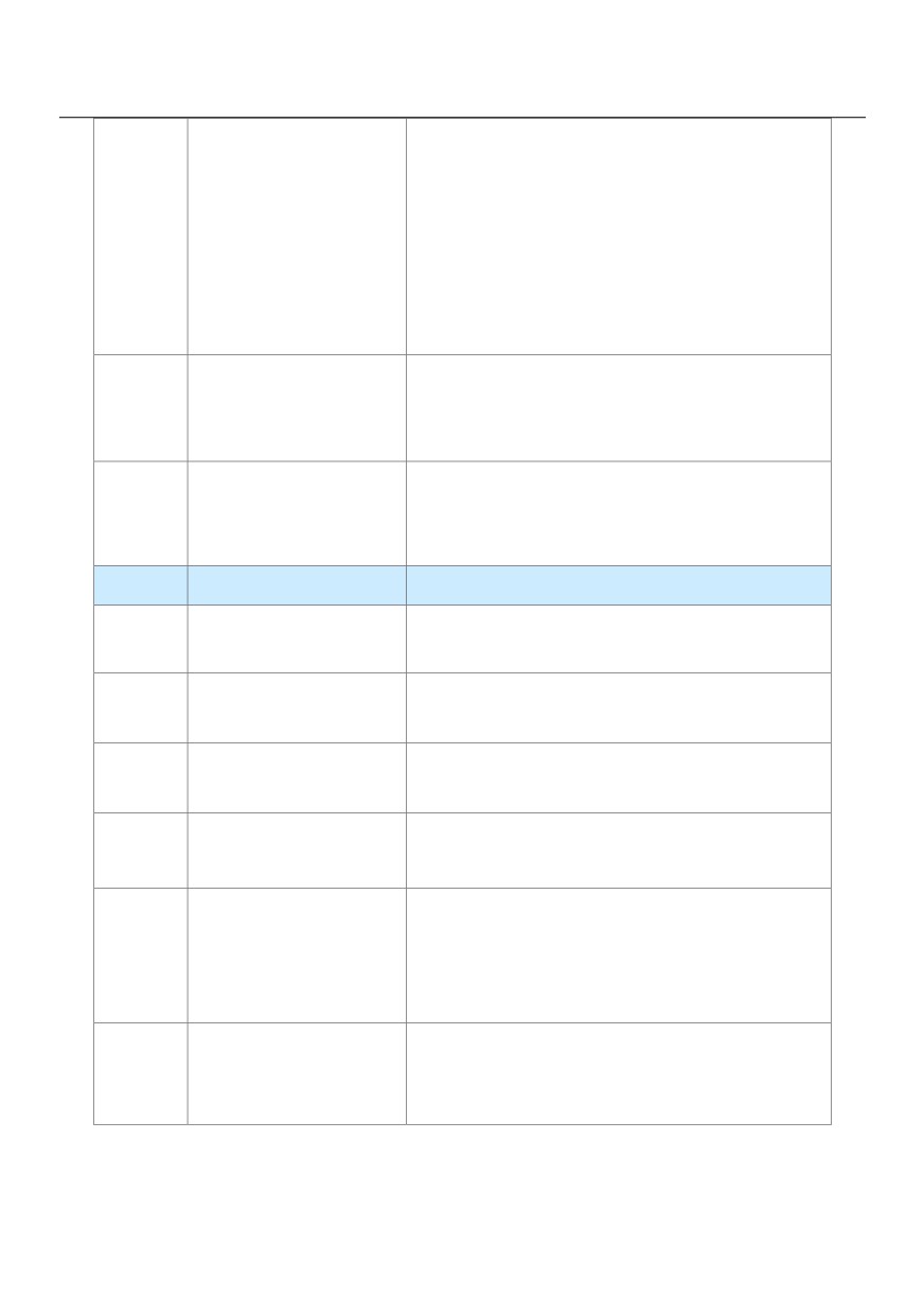
The AC drive judges whether the motor load exceeds the
overload pre-warning threshold before performing the
Motor overload
6
protection action. If the pre-warning threshold is
pre-warning
exceeded, the terminal becomes ON. For motor overload
parameters, see the descriptions of P9-00 to P9-02.
AC drive overload
The terminal becomes ON 10s before the AC drive
7
pre-warning
overload protection action is performed.
The terminal becomes ON when the count value reaches
8
Set count value reached
the value set in PB-08.
Value
Function
Description
Designated count
The terminal becomes ON when the count value reaches
9
value reached
the value set in PB-09.
The terminal becomes ON when the detected actual
10
Length reached
length exceeds the value set in PB-05
When simple PLC completes one cycle, the terminal
11
PLC cycle complete
outputs a pulse signal with width of 250 ms.
Accumulative running
If the accumulative running time of the AC drive exceeds
12
time reached
the time set in P8-17, the terminal becomes ON.
If the set frequency exceeds the frequency upper limit or
lower limit and the output frequency of the AC drive
13
Frequency limited
reaches the upper limit or lower limit, the terminal
becomes ON.
In speed control mode, if the output torque reaches the
14
Torque limited
torque limit, the AC drive enters the stall protection state
and meanwhile the terminal becomes ON.
118
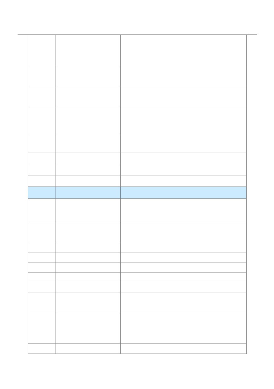
If the AC drive main circuit and control circuit become
15
Ready for RUN
stable, and the AC drive detects no fault and is ready for
RUN, the terminal becomes ON.
When the input of AI1 is larger than the input of AI2, the
16
VS>AS
terminal becomes ON.
Frequency upper limit
If the running frequency reaches the upper limit, the
17
Reached
terminal becomes ON.
Frequency lower limit
If the running frequency reaches the lower limit, the
18
reached (no output at
terminal becomes ON. In the stop state, the terminal
stop)
becomes OFF.
If the AC drive is in undervoltage state, the terminal
19
Undervoltage state output
becomes ON.
20
Communication setting
Refer to the communication protocol.
21
Reserved
Reserved.
22
Reserved
Reserved.
Value
Function
Description
Zero-speed running 2
If the output frequency of the AC drive is 0, the terminal
23
(having output at stop)
becomes ON. In the state of stop, the signal is still ON.
Accumulative power-on time
If the AC drive accumulative power-on time (P7-13)
24
reached
exceeds the value set in P8-16, the terminal becomes
25
Frequency level
Refer to the descriptions of P8-28 and P8-29.
26
Frequency 1 reached
Refer to the descriptions of P8-30 and P8-31.
27
Frequency 2 reached
Refer to the descriptions of P8-32 and P8-33.
28
Current 1 reached
Refer to the descriptions of P8-38 and P8-39.
29
Current 2 reached
Refer to the descriptions of P8-40 and P8-41.
If the timing function (P8-42) is valid, the terminal becomes ON
30
Timing reached
after the current running time of the AC drive reaches the set
time.
If AI1 input is larger than the value of P8-46 (AI1 input
31
VS input limit exceeded
voltage upper limit) or lower than the value of P8-45 (AI1
input voltage lower limit), the terminal becomes ON.
32
Load becoming 0
If the load becomes 0, the terminal becomes ON.
119
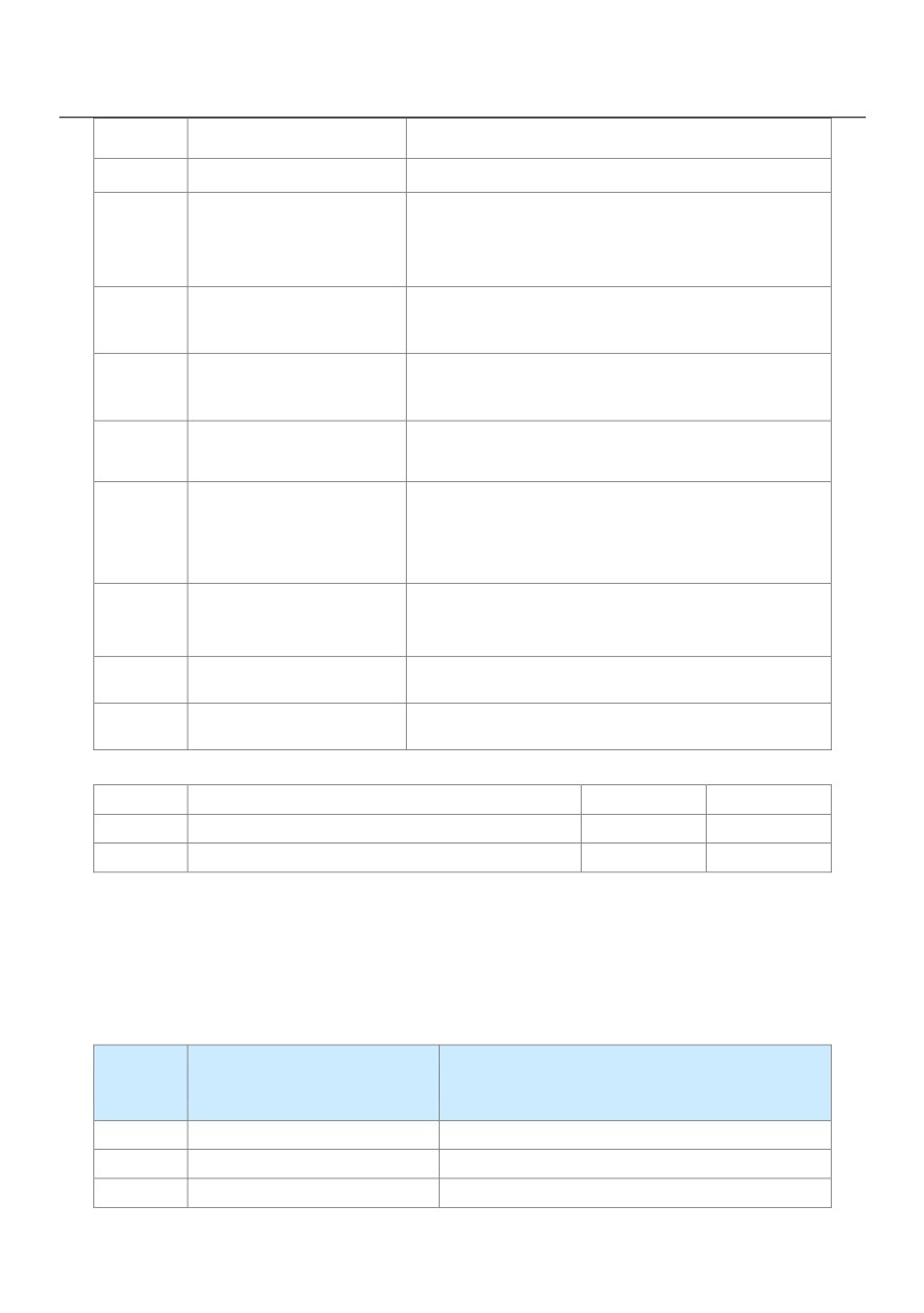
33
Reverse running
If the AC drive is in the reverse running state, the terminal
34
Zero current state
Refer to the descriptions of P8-28 and P8-29.
If the heatsink temperature of the inverter module (P7-07)
Module temperature
35
reaches the set module temperature threshold (P8-47),
reached
the terminal becomes ON.
Software current limit
36
Refer to the descriptions of P8-36 and P8-37.
exceeded
Frequency lower limit reached
If the running frequency reaches the lower limit, the terminal
37
(having output at stop)
becomes ON. In the stop state, the signal is still ON.
If a fault occurs on the AC drive and the AC drive
38
Alarm output
continues to run, the terminal outputs the alarm signal.
If the motor temperature reaches the temperature set in
Motor overheat
39
P9-58 (Motor overheat warning threshold), the terminal
warning
becomes ON. You can view the motor temperature by
using U0-34.
Current running time
If the current running time of AC drive exceeds the value
40
reached
of P8-53, the terminal becomes ON
42
Mechanical Brake
Mechanical Brake output
43
Main Contactor
Main Contactor output
P5-06
Y2P function selection (Pulse output terminal)
Default
0
P5-07
AO1 function selection
Default
0
P5-08
AO2 function selection
Default
1
The output pulse frequency of the Y2P terminal ranges from 0.01 kHz to "Maximum Y2P output frequency"
(P5-09). The value of P5-09 is between 0.01 kHz and 100.00 kHz.
The output range of AO1 and AO2 is 0-10 V or 0-20 mA.
The relationship between pulse and analog output ranges and corresponding functions is listed in the
following table.
Range (Corresponding to Pulse or Analog Output
Value
Function
Range 0.0%-100.0%)
0
Running frequency
0 to maximum output frequency
1
Set frequency
0 to maximum output frequency
2
Output current
0 to 2 times of rated motor current
120
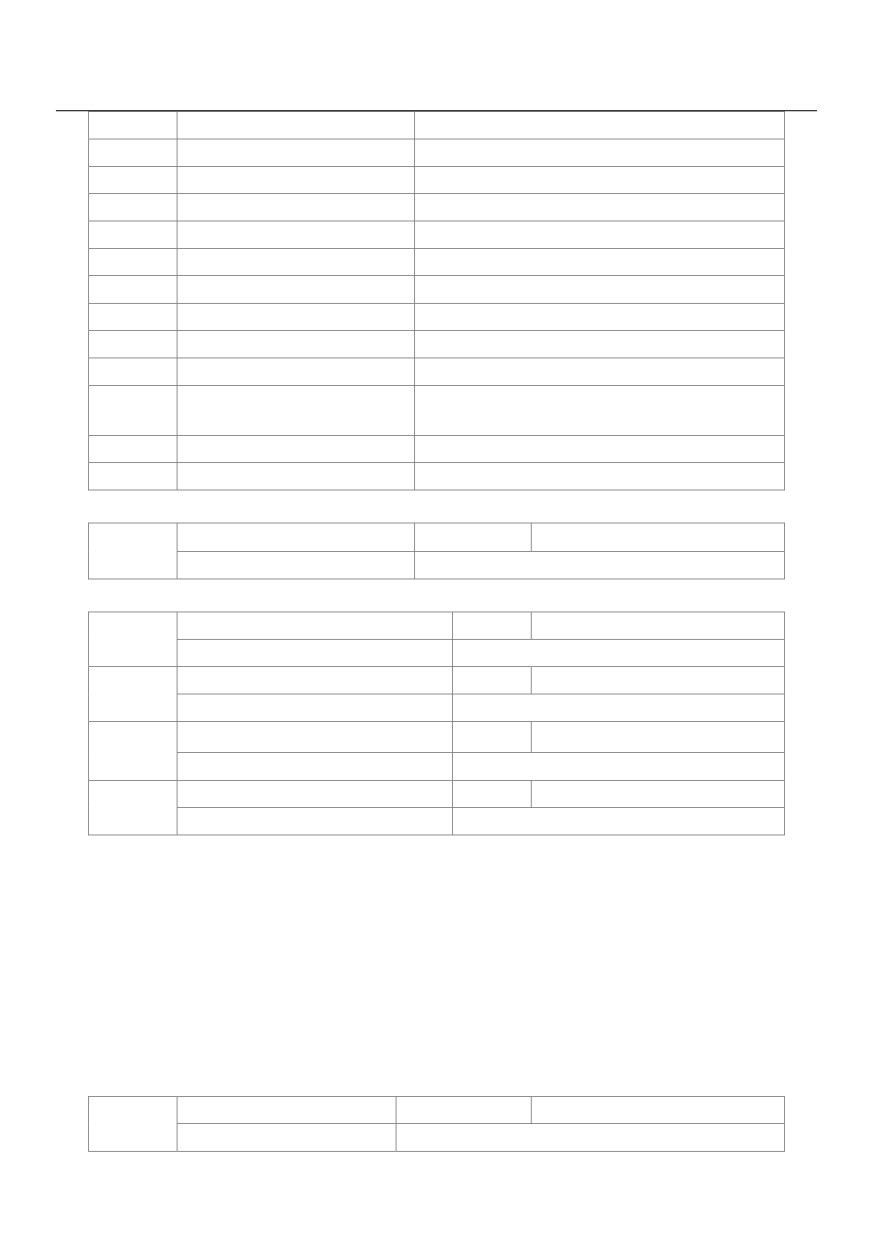
3
Output torque (absolute value)
0 to 2 times of rated motor torque
4
Output power
0 to 2 times of rated power
5
Output voltage
0 to 1.2 times of rated AC drive voltage
6
Pulse input
0.01kHz ~ 100.00kHz
7
VS
0V ~ 10V
8
AS
0V ~ 10V (Or 0 ~ 20mA)
9
VS2
0V ~ 10V
10
Length
0 ~maximum set length
11
Count value
0 ~maximum count value
12
Communication setting
0.0% ~ 100.0%
0 ~ rotational speed corresponding to maximum
13
Motor rotational speed
output frequency
14
Output current
0.0A ~ 1000.0A
15
Output voltage
0.0V ~ 1000.0V
Maximum Y2P output frequency
Default
50.00kHz
P5-09
Setting Range
0.01kHz ~ 100.00kHz
If the Y2 terminal is used for pulse output, this parameter is used to set the maximum frequency of pulse output.
AO1 offset coefficient
Default
0.0%
P5-10
Setting Range
-100.0% ~ +100.0%
AO1 gain
Default
1.00
P5-11
Setting Range
-10.00 ~ +10.00
Expansion card AO2 offset coefficient
Default
0.00%
P5-12
Setting Range
-100.0% ~ +100.0%
Expansion card AO2 gain
Default
1.00
P5-13
Setting Range
-10.00 ~ +10.00
These parameters are used to correct the zero drift of analog output and the output amplitude deviation. They
can also be used to define the desired AO curve.
If "b" represents zero offset, "k" represents gain, "Y" represents actual output, and "X" represents standard
output, the actual output is: Y = kX + b.
The zero offset coefficient 100% of AO1 and AO2 corresponds to 10 V (or 20 mA). The standard output refers
to the value corresponding to the analog output of 0 to 10 V (or 0 to 20 mA) with no zero offset or gain
adjustment.
For example, if the analog output is used as the running frequency, and it is expected that the output is 8 V
when the frequency is 0 and 3 V at the maximum frequency, the gain shall be set to -0.50, and the zero offset
shall be set to 80%.
Y2R output delay time
Default
0.0s
P5-17
Setting Range
0.0s ~ 3600.0s
121
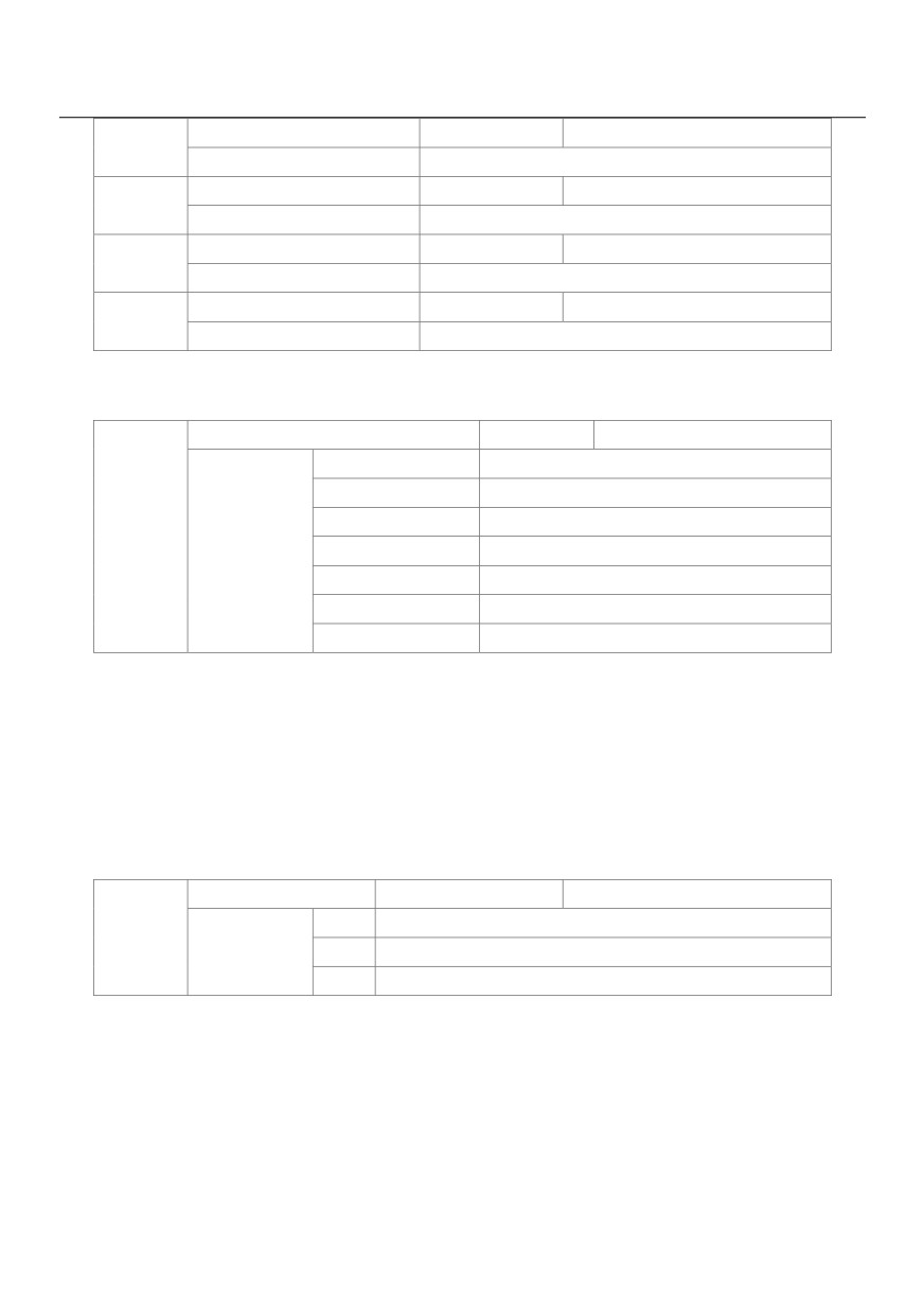
RELAY1 output delay time
Default
0.0s
P5-18
Setting Range
0.0s ~ 3600.0s
RELAY2 output delay time
Default
0.0s
P5-19
Setting Range
0.0s ~ 3600.0s
Y1 output delay time
Default
0.0s
P5-20
Setting Range
0.0s ~ 3600.0s
DO2 output delay time
Default
0.0s
P5-21
Setting Range
0.0s ~ 3600.0s
These parameters are used to set the delay time of output terminals Y2R, relay 1, relay 2, Y1 and DO2 from
status change to actual output.
DO valid mode selection
Default
00000
Unit's digit
Y2R valid mode
0
Positive logic
1
Negative logic
P5-22
Setting Range
Ten's digit
RELAY1 valid mode(0 ~ 1, same as Y2R)
Hundred's digit
RELAY2 valid mode(0 ~ 1, same as Y2R)
Thousand's digit
Y1 valid mode(0 ~ 1, same as Y2R)
Ten thousand's digit
Y2 valid mode(0 ~ 1, same as Y2R)
It is used to set the logic of output terminals Y2R, relay 1, relay 2, Y1 and Y2.
0: Positive logic
The output terminal is valid when being connected with COM, and invalid when being disconnected from COM.
1: Negative logic
The output terminal is invalid when being connected with COM, and valid when being disconnected from COM
Group P6 Start/Stop Control
Start mode
Default
0
0
Direct start
P6-00
Setting Range
1
Rotational speed tracking restart
2
Pre-excited start (asynchronous motor)
0: Direct start
- If the DC braking time is set to 0, the AC drive starts to run at the startup frequency.
- If the DC braking time is not 0, the AC drive performs DC braking first and then starts to run at the startup
frequency. It is applicable to small-inertia load application where the motor is likely to rotate at startup.
1: Rotational speed tracking restart
The AC drive judges the rotational speed and direction of the motor first and then starts at the tracked
122
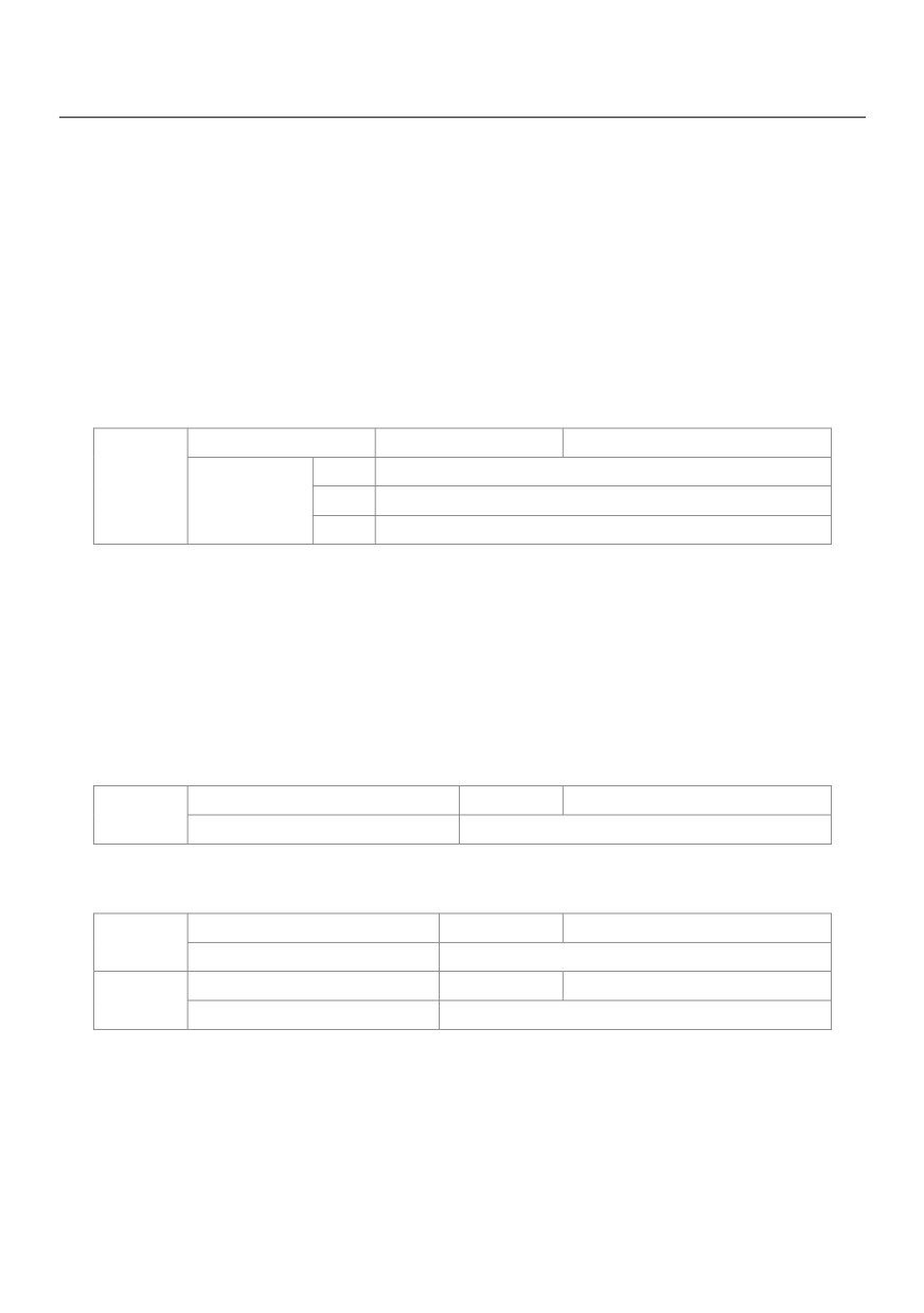
frequency. Such smooth start has no impact on the rotating motor. It is applicable to the restart upon
instantaneous power failure of large-inertia load. To ensure the performance of rotational speed tracking
restart, set the motor parameters in group P1 correctly.
2: Pre-excited start (asynchronous motor)
It is valid only for asynchronous motor and used for building the magnetic field before the motor runs. For
pre-excited current and pre-excited time, see parameters of P6-05 and P6-06.
- If the pre-excited time is 0, the AC drive cancels pre-excitation and starts to run at startup frequency.
- If the pre-excited time is not 0, the AC drive pre-excites first before startup, improving the dynamic
response of the motor.
Rotational speed
Default
0
0
From frequency at stop
P6-01
Setting Range
1
From zero speed
2
From maximum frequency
To complete the rotational speed tracking process within the shortest time, select the proper mode in which
the AC drive tracks the motor rotational speed.
0: From frequency at stop
It is the commonly selected mode.
1: From zero frequency
It is applicable to restart after a long time of power failure.
2: From the maximum frequency, it is applicable to the power-generating load.
Rotational speed tracking speed
Default
20
P6-02
Setting Range
1 ~ 100
In the rotational speed tracking restart mode, select the rotational speed tracking speed. The larger the value
is, the faster the tracking is. However, too large value may cause unreliable tracking.
Startup frequency
Default
0.00Hz
P6-03
Setting Range
0.00Hz ~ 10.00Hz
Startup frequency holding time
Default
0.0s
P6-04
Setting Range
0.0s ~ 100.0s
To ensure the motor torque at AC drive startup, set a proper startup frequency. In addition, to build excitation
when the motor starts up, the startup frequency must be held for a certain period.
The startup frequency (P6-03) is not restricted by the frequency lower limit. If the set target frequency is lower
than the startup frequency, the AC drive will not start and stays in the standby state.
During switchover between forward rotation and reverse rotation, the startup frequency holding time is
123