HV580L Series Frequency Inverter. User Manual (Version: 3.1.14) - page 3

Function
Parameter Name
Setting Range
Default
Property
Code
Unit's digit (User-defined fault 1, Err27)
0: Coast to stop
1: Stop according to the stop mode
2: Continue to run
Ten's digit (User-defined fault 2, Err28)
0: Coast to stop
1: Stop according to the stop mode
2: Continue to run
Fault protection action
P9-49
Hundred's digit (Accumulative power-on
00000
☆
selection 3
time reached, Err29)
0: Coast to stop
1: Stop according to the stop mode
2: Continue to run
Thousand's digit (Load becoming 0, Err30)
1: Coast to stop
2: Continue to run at 7% of rated motor
frequency and resume to the set frequency
if the load recovers
Unit's digit (Too large speed deviation,
Err42)
0: Coast to stop
Fault protection action
P9-50
1: Stop according to the stop mode
00000
☆
selection 4
2: Continue to run
Ten's digit (Motor over-speed, Err43)
Hundred's digit (Initial position fault, Err51)
0: Current running frequency
1: Set frequency
Frequency selection for
P9-54
2: Frequency upper limit
0
☆
continuing to run upon fault
3: Frequency lower limit
4: Backup frequency upon abnormality
Backup frequency upon
0.0% ~ 100.0%
P9-55
100.0%
☆
abnormality
(100.0% maximum frequency P0-10)
Type of motor temperature
0: No temperature sensor
P9-56
0
☆
sensor
1: PT100
2: PT1000
62

Function
Parameter Name
Setting Range
Default
Property
Code
Motor overheat protection
P9-57
0℃~ 200℃
110℃
☆
threshold
Motor overheat warning
P9-58
0℃~ 200℃
90℃
☆
threshold
0: Invalid
Action selection at
P9-59
1: Decelerate
0
☆
instantaneous power failure
2: Decelerate to stop
Action pause judging voltage
P9-60
80.0% ~ 100.0%
90.0%
☆
at instantaneous power
failure
Voltage rally judging time at
P9-61
0.00s ~ 100.00s
0.50s
☆
instantaneous power failure
Action judging voltage at
P9-62
60.0% ~ 100.0%(standard bus voltage)
80.0%
☆
instantaneous power failure
Protection upon load
0: Disabled
P9-63
0
☆
becoming 0
1: Enabled
Detection level of load
P9-64
0.0 ~ 100.0%
10.0%
☆
becoming 0
Detection time of load
P9-65
0.0 ~ 60.0s
1.0s
☆
becoming 0
P9-67
Over-speed detection value
0.0%~ 50.0% (maximum frequency)
20.0%
☆
P9-68
Over-speed detection time
0.1 ~ 60.0s
5.0s
☆
P9-69
Detection value of too large
0.0%~ 50.0% (maximum frequency)
20.0%
☆
speed deviation
P9-70
Detection time of too large
0.1 ~ 60.0s
0.0s
☆
speed deviation
63
Function
Parameter Name
Setting Range
Default
Property
Code
Group PA: Process Control PID Function
0: PA-01 setting
1: VS
2: AS
PA-00
PID setting source
3: VS2
0
☆
4: PULSE setting (X5)
5: Communication setting
6: Multi-reference
PA-01
PID digital setting
0.0% ~ 100.0%
50.0%
☆
0: VS
1: AS
2: VS2
3: VS-AS
PA-02
PID feedback source
4: PULSE setting (X5)
0
☆
5: Communication setting
6: VS+AS
7: MAX(|VS|, |AS|)
8: MIN(|VS|, |AS|)
0: Forward action
PA-03
PID action direction
0
☆
1: Reverse action
PA-04
PID setting feedback range
0 ~ 65535
1000
☆
PA-05
Proportional gain Kp1
0.0 ~ 100.0
20.0
☆
PA-06
Integral time Ti1
0.01s ~ 10.00s
2.00s
☆
PA-07
Differential time Td1
0.000s ~ 10.000s
0.000s
☆
Cut-off frequency of PID reverse0.00 ~ maximum frequency
PA-08
2.00Hz
☆
rotation
0.0% ~ 100.0%
PA-09
PID deviation limit
0.0%
☆
PA-10
PID differential limit
0.00% ~ 100.00%
0.10%
☆
0.00 ~ 650.00s
PA-11
PID setting change time
0.00s
☆
PA-12
PID feedback filter time
0.00 ~ 60.00s
0.00s
☆
64
Function
Parameter Name
Setting Range
Default
Property
Code
PA-13
PID output filter time
0.00 ~ 60.00s
0.00s
☆
PA-14
Reserved
-
-
☆
PA-15
Proportional gain Kp2
0.0 ~ 100.0
20.0
☆
PA-16
Integral time Ti2
0.01s ~ 10.00s
2.00s
☆
PA-17
Differential time Td2
0.000s ~ 10.000s
0.000s
☆
PID parameter switchover
0: No switchover
PA-18
0
☆
condition
1: Switchover via DI
PID parameter switchover
0.0% ~ PA-20
PA-19
20.0%
☆
deviation 1
PID parameter switchover
PA-19 ~ 100.0%
PA-20
80.0%
☆
deviation 2
PA-21
PID initial value
0.0% ~ 100.0%
0.0%
☆
PA-22
PID initial value holding time
0.00 ~ 650.00s
0.00s
☆
Maximum deviation between
0.00% ~ 100.00%
PA-23
two PID outputs in forward
1.00%
☆
direction
Maximum deviation between
0.00% ~ 100.00%
PA-24
two PID outputs in reverse
1.00%
☆
direction
Unit's digit (Integral separated)
0: Invalid
1: Valid
Ten's digit (Whether to stop integral
PA-25
PID integral property
operation when the output reaches the
00
☆
limit)
0: Continue integral operation
1: Stop integral operation
Detection value of PID feedback0.0%:Not judging feedback loss
PA-26
0.0%
☆
loss
0.1% ~ 100.0%
PA-27
Detection time of PID feedback
0.0s ~ 20.0s
0.0s
☆
0: No PID operation at stop
0
PA-28
PID operation at stop
☆
1: PID operation at stop
65
Function
Parameter Name
Setting Range
Default
Property
Code
Group PB: Swing Frequency, Fixed Length and Count
0: Relative to the central frequency
Pb-00
Swing frequency setting mode
0
☆
1: Relative to the maximum frequency
Pb-01
Swing frequency amplitude
0.0% ~ 100.0%
0.0%
☆
Pb-02
Jump frequency amplitude
0.0% ~ 50.0%
0.0%
☆
Pb-03
Swing frequency cycle
0.1s ~ 3000.0s
10.0s
☆
Triangular wave rising time
Pb-04
0.1% ~ 100.0%
50.0%
☆
coefficient
Pb-05
Set length
0m ~ 65535m
1000m
☆
Pb-06
Actual length
0m ~ 65535m
0m
☆
Pb-07
Number of pulses per meter
0.1 ~ 6553.5
100.0
☆
Pb-08
Set count value
1 ~ 65535
1000
☆
Pb-09
Designated count value
1 ~ 65535
1000
☆
Group PC: Multi-Reference and Simple PLC Function
PC-00
Reference 0
-100.0% ~ 100.0%
10.0%
☆
PC-01
Reference 1
-100.0% ~ 100.0%
100.0%
☆
PC-02
Reference 2
-100.0% ~ 100.0%
11.0%
☆
PC-03
Reference 3
-100.0% ~ 100.0%
12.0%
☆
PC-04
Reference 4
-100.0% ~ 100.0%
40.0%
☆
PC-05
Reference 5
-100.0% ~ 100.0%
13.0%
☆
PC-06
Reference 6
-100.0% ~ 100.0%
14.0%
☆
PC-07
Reference 7
-100.0% ~ 100.0%
15.0%
☆
PC-08
UPS reference frequency
-100.0% ~ 100.0%
10.0%
☆
PC-09
Reference 9
-100.0% ~ 100.0%
0.0%
☆
PC-10
Reference 10
-100.0% ~ 100.0%
0.0%
☆
PC-11
Reference 11
-100.0% ~ 100.0%
0.0%
☆
PC-12
Reference 12
-100.0% ~ 100.0%
0.0%
☆
PC-13
Reference 13
-100.0% ~ 100.0%
0.0%
☆
PC-14
Reference 14
-100.0% ~ 100.0%
0.0%
☆
PC-15
Reference 15
-100.0% ~ 100.0%
0.0%
☆
66

Function
Parameter Name
Setting Range
Default
Property
Code
0: Stop after the AC drive runs one cycle
1: Keep final values after the AC drive
PC-16
Simple PLC running mode
runs one cycle
0
☆
2: Repeat after the AC drive runs one
cycle
Unit's digit (Retentive upon power
failure)
0: No
PC-17
Simple PLC retentive selection
1: Yes
00
☆
Ten's digit (Retentive upon stop)
0: No
1: Yes
Running time of simple PLC
PC-18
0.0s(h) ~ 6553.5s(h)
0.0s(h)
☆
reference 0
Acceleration/deceleration time
0 ~ 3
PC-19
0
☆
of simple PLC reference 0
Running time of simple PLC
0.0s(h) ~ 6553.5s(h)
PC-20
0.0s(h)
☆
reference 1
Acceleration/deceleration time
0 ~ 3
PC-21
0
☆
of simple PLC reference 1
Running time of simple PLC
0.0s(h) ~ 6553.5s(h)
PC-22
0s(h)
☆
reference 2
Acceleration/deceleration time
0 ~ 3
PC-23
0
☆
of simple PLC reference 2
Running time of simple PLC
0.0s(h) ~ 6553.5s(h)
PC-24
0.0s(h)
☆
reference 3
Acceleration/deceleration time
0 ~ 3
PC-25
0
☆
of simple PLC reference 3
Running time of simple PLC
0.0s(h) ~ 6553.5s(h)
PC-26
0.0s(h)
☆
reference 4
67

Function
Parameter Name
Setting Range
Default
Property
Code
Acceleration/deceleration time of
0 ~ 3
PC-27
0
☆
simple PLC reference 4
Running time of simple PLC
0.0s(h) ~ 6553.5s(h)
PC-28
0.0s(h)
☆
reference 5
Acceleration/deceleration time of
0 ~ 3
PC-29
0
☆
simple PLC reference 5
Running time of simple PLC
0.0s(h) ~ 6553.5s(h)
PC-30
0.0s(h)
☆
reference 6
Acceleration/deceleration time of
0 ~ 3
PC-31
0
☆
simple PLC reference 6
Running time of simple PLC
0.0s(h) ~ 6553.5s(h)
0.0s(h)
☆
PC-32
reference 7
Acceleration/deceleration time of
0 ~ 3
0
☆
PC-33
simple PLC reference 7
Running time of simple PLC
0.0s(h) ~ 6553.5s(h)
0.0s(h)
☆
PC-34
reference 8
Acceleration/deceleration time of
0 ~ 3
0
☆
PC-35
simple PLC reference 8
Running time of simple PLC
0.0s(h) ~ 6553.5s(h)
0.0s(h)
☆
PC-36
reference 9
Acceleration/deceleration time
0 ~ 3
0
☆
PC-37
of simple PLC reference 9
Running time of simple PLC
0.0s(h) ~ 6553.5s(h)
0.0s(h)
☆
PC-38
reference 10
Acceleration/deceleration time
0 ~ 3
0
☆
PC-39
of simple PLC reference 10
Running time of simple PLC
0.0s(h) ~ 6553.5s(h)
0.0s(h)
☆
PC-40
reference 11
Acceleration/deceleration time
0 ~ 3
0
☆
PC-41
of simple PLC reference 11
68

Function
Parameter Name
Setting Range
Default
Property
Code
Running time of simple PLC
0.0s(h) ~ 6553.5s(h)
0.0s(h)
☆
PC-42
reference 12
Acceleration/deceleration time
0 ~ 3
0
☆
PC-43
of simple PLC reference 12
Running time of simple PLC
0.0s(h) ~ 6553.5s(h)
0.0s(h)
☆
PC-44
reference 13
Acceleration/deceleration time
0 ~ 3
0
☆
PC-45
of simple PLC reference 13
Running time of simple PLC
0.0s(h) ~ 6553.5s(h)
0.0s(h)
☆
PC-46
reference 14
Acceleration/deceleration time
0 ~ 3
0
☆
PC-47
of simple PLC reference 14
Running time of simple PLC
0.0s(h) ~ 6553.5s(h)
0.0s(h)
☆
PC-48
reference 15
Acceleration/deceleration time
0 ~ 3
0
☆
PC-49
of simple PLC reference 15
0: s (second)
PC-50
Time unit of simple PLC running
0
☆
1: h (hour)
0: Set by PC-00
1: VS
2:AS
3: VS2
PC-51
Reference 0 source
4: PULSE setting
0
☆
5: PID
6: Set by preset frequency (P0-08),
modified via terminal UP/DOWN
69
Function
Parameter Name
Setting Range
Default
Property
Code
Group Pd: Communication Parameters
Unit’s digit: MODBUS 0: 300BPS
1: 600BPS
2: 1200BPS
3: 2400BPS
4: 4800BPS
5: 9600BPS
6: 19200BPS
7: 38400BPS
8: 57600BPS
9: 115200BPS
Ten’s digit: Profibus-DP
0: 115200BPs
Pd-00
Baud rate
6005
☆
1: 208300BPs
2: 256000BPs
3: 512000Bps
Hundred’s digit (reserved)
Thousand’s digit: CANlink baud rate
0: 20
1: 50
2: 100
3: 125
4: 250
5: 500
6: 1M
0: No check, data format (8-N-2)
1: Even parity check, data format (8-E-1)
Pd-01
MODBUS Data format
2: Odd parity check, data format (8-O-1)
0
☆
3: No check, data format (8-N-1) (Valid for
MODBUS)
70
Function
Parameter Name
Setting Range
Default
Property
Code
0: Broadcast address
Pd-02
Local address
1
☆
1 ~ 247
Pd-03
MODBUS Response delay
0 ~ 20ms (Valid for MODBUS)
2
☆
0.0: invalid
0.1 ~ 60.0s
Pd-04
Communication timeout
0.0
☆
(Valid for MODBUS, Profibus-DP, and
CANopen)
Unit’s digit: MODBUS
0: Non-standard Modbus protocol
1: Standard Modbus protocol
Modbus protocol selection and
Ten’s digit: Profibus-DP
Pd-05
30
☆
PROFIBUS-DP data format
0: PPO1 format
1: PPO2 format
2: PPO3 format
3: PPO5 format
Communication reading current
0: 0.01A
Pd-06
0
☆
resolution
1: 0.1A
Canlink communication timeout
0.0s: Invalid
Pd-08
0
☆
time
0.1~60.0s
Group PP: Function Code Management
PP-00
User password
0~65535
0
☆
0: No operation
01: Restore factory settings except motor
parameters
PP-01
Restore default settings
0
★
02: Clear records
04: Restore user backup parameters
501: Back up current user parameters
71

Function
Parameter Name
Setting Range
Default
Property
Code
Unit's digit (Group U display selection)
0: Not display
AC drive parameter display
1: Display
PP-02
11
★
property
Ten's digit (Group A display selection)
0: Not display
1: Display
Unit's digit (User-defined parameter display
selection)
0: Not display
Individualized parameter display1: Display
PP-03
00
☆
property
Ten's digit (User-modified parameter
display selection)
0: Not display
1: Display
0: Modifiable
PP-04
Parameter modification property
0
☆
1: Not modifiable
Group A0: Torque Control and Restricting Parameters
0: Speed control
A0-00
Speed/Torque control selection
0
★
1: Torque control
0: Digital setting 1(A0-03)
1: VS
2: AS
3: VS2
Torque setting source in torque
A0-01
4: PULSE setting
0
★
control
5: Communication setting
6: MIN(VS,AS)
7: MAX(VS,AS) Full range of values 1-7
corresponds to the digital setting of A0-03
72
Function
Parameter Name
Setting Range
Default
Property
Code
Torque digital setting in torque
A0-03
-200.0% ~ 200.0%
150.0%
☆
control
Forward maximum frequency in
A0-05
0.00Hz ~maximum frequency
50.00Hz
☆
torque control
Reverse maximum frequency in
A0-06
0.00Hz ~maximum frequency
50.00Hz
☆
torque control
Acceleration time in torque
A0-07
0.00s ~ 65000s
0.00s
☆
control
Deceleration time in torque
A0-08
0.00s ~ 65000s
0.00s
☆
control
Table 5-2 Monitoring Parameters
Communication
Function Code
Parameter Name
Min. Unit
Address
Group C: Standard Monitoring Parameters
C-00
Running frequency (Hz)
0.01Hz
7000H
C-01
Set frequency (Hz)
0.01Hz
7001H
C-02
Bus voltage (V)
0.1V
7002H
C-03
Output voltage (V)
1V
7003H
C-04
Output current (A)
0.01A
7004H
C-05
Output power (kW)
0.1kW
7005H
C-06
Output torque (%)
0.1%
7006H
C-07
X state
1
7007H
C-08
DO state
1
7008H
C-09
VS voltage (V)
0.01V
7009H
C-10
AS voltage (V)/ current (mA)
0.01V/0.01mA
700AH
C-11
VS2 voltage (V)
0.01V
700BH
C-12
Count value
1
700CH
C-13
Length value
1
700DH
C-14
Load speed
1
700EH
C-15
PID setting
1
700FH
C-16
PID feedback
1
7010H
73
Communication
Function Code
Parameter Name
Min. Unit
Address
C-17
PLC stage
1
7011H
C-18
Input pulse frequency (Hz)
0.01kHz
7012H
C-19
Feedback speed (Hz)
0.01Hz
7013H
C-20
Remaining running time
0.1Min
7014H
C-21
VS voltage before correction
0.001V
7015H
C-22
AS voltage (V) / current (mA) before correction
0.001V/0.01mA
7016H
C-23
VS2 voltage before correction
0.001V
7017H
C-24
Linear speed
1m/Min
7018H
C-25
Accumulative power-on time
1Min
7019H
C-26
Accumulative running time
0.1Min
701AH
C-27
PULSE input frequency
1Hz
701BH
C-28
Communication setting value
0.01%
701CH
C-29
Encoder feedback speed
0.01Hz
701DH
C-30
Main frequency X
0.01Hz
701EH
C-31
Auxiliary frequency Y
0.01Hz
701FH
C-32
Viewing any register address value
1
7020H
C-33
Synchronous motor rotor position
0.1°
7021H
C-34
Motor temperature
1℃
7022H
C-35
Target torque (%)
0.1%
7023H
C-36
Resolver position
1
7024H
C-37
Power factor angle
0.1°
7025H
C-38
ABZ position
1
7026H
C-39
Target voltage upon V/F separation
1V
7027H
C-40
Output voltage upon V/F separation
1V
7028H
C-41
X state visual display
1
7029H
C-42
DO state visual display
1
702AH
C-43
X function state visual display 1 (function 01-40)
1
702BH
C-44
X function state visual display 2 (function 41- 80)
1
702CH
C-45
Fault information
1
702DH
C-58
Phase Z counting
1
703AH
C-59
Current set frequency (%)
0.01%
703BH
C-60
Current running frequency (%)
0.01%
703CH
C-61
AC drive running state
1
703DH
C-62
Current fault code
1
703EH
C-63
Reserved
-
-
C-65
Torque upper limit
0.1%
7041H
74
Chapter 6 Description of Function Codes
Group P0: Basic Parameters
GP type display
Default
Model dependent
P0-00
1
G type (constant torque load)
Setting Range
2
P type (variable torque load e.g. fan and pump)
This parameter is used to display the delivered model and cannot be modified
1: Applicable to constant torque load with rated parameters specified
2: Applicable to variable torque load (fan and pump) with rated parameters specified
Motor 1 control mode
Default
2
P0-01
0
Sensor less flux vector control (SVC)
Setting Range
2
Voltage/Frequency (V/F) control
0: Sensor less flux vector control (SVC)
It indicates open-loop vector control, and is applicable to high-performance control applications such as
machine tool, centrifuge, wire drawing machine and injection moulding machine. One AC drive can operate
only one motor.
2: Voltage/Frequency (V/F) control
It is applicable to applications with low load requirements or applications where one AC drive operates multiple
motors, such as fan and pump.
Note: If vector control is used, motor auto-tuning must be performed because the advantages of vector control
can only be utilized after correct motor parameters are obtained. Better performance can be achieved by
adjusting speed regulator parameters in group P2 (or groups A2, A3, and A4 respectively for motor 2, 3, and 4).
For the permanent magnetic synchronous motor (PMSM), the HV580L does not support SVC. FVC is used
generally. In some low-power motor applications, you can also use V/F.
Command source
Default
0
selection
P0-02
0
Operation panel control (LED off)
Setting Range
1
Terminal control (LED on)
2
Communication control (LED blinking)
It is used to determine the input channel of the AC drive control commands, such as run, stop, forward rotation,
reverse rotation and jog operation.
75
0:Operation panel control channel (“LOCAL/REMOT” indicator off)
Commands are given by pressing keys “RUN” and “STOP/RES” on the operation panel
1:Terminal control (“LOCAL /REMOT” indicator on)
Commands are given by means of multifunctional input terminals with functions such as FWD, REV, JOGF,
and JOGR.
2:Communication control channel (“LOCAL/REMOT” indicator blinking)
Commands are given from host computer. If this parameter is set to 2, a communication card (Modbus RTU,
PROFIBUS-DP card, CANlink card, user programmable card or CANopen card) must be installed
Related to the communication function parameters, please see the "PD group communication parameters"
instructions, and reference the corresponding communication card, the appendix of this manual contains brief
explanation of communication card.
Main frequency source X
Default
0
selection
Digital setting ( Preset frequency P0-08, UP/DOWN
0
revisable, non-retentive at power failure)
Digital setting (Preset frequency P0-08, UP/DOWN revisable,
1
retentive at power failure)
P0-03
2
VS
3
AS
Setting Range
4
VS2
5
Pulse setting (X5)
6
Multi-reference
7
PLC
8
PID
9
Communication setting
It is used to select the setting channel of the main frequency. You can set the main frequency in the following
10 channels:
0: Digital setting (non-retentive at power failure)
The initial value of the set frequency is the value of P0-08 (Preset frequency). You can change the set
frequency by pressing ▲ and ▼ on the operation panel (or using the UP/DOWN functions of input terminals).
When the AC drive is powered on again after power failure, the set frequency reverts to the value of P0-08.
1: Digital setting (retentive at power failure)
The initial value of the set frequency is the value of P0-08 (Preset frequency). You can change the set
frequency by pressing keys ▲ and ▼ on the operation panel (or using the UP/DOWN functions of input
76
terminals).
When the AC drive is powered on again after power failure, the set frequency is the value memorized at the
moment of the last power failure.
Note that P0-23 (Retentive of digital setting frequency upon power failure) determines whether the set
frequency is memorized or cleared when the AC drive stops. It is related to stop rather than power failure.
2: VS
3: AS
4: VS2
The frequency is set by analog input. The HV580L control board provides two analog input terminals (VS, AS).
Another AI terminal (VS2) is provided by the I/O extension card.
VS is 0V~10V voltage input, AS can be 0V~10V voltage input, or 4mA ~ 20mA current input, it is
determined by jumper J8, VS2 is -10V~10V voltage input.
The HV580L provides five curves indicating the mapping relationship between the input voltages of VS, AS
and VS2 and the target frequency, three of which are linear (point - point) correspondence and two of which
are four-point correspondence curves. You can set the curves by using function codes P4-13 to P4-27 and
function codes in group A6, and select curves for VS~VS2 in P4-33. For the five curves specific corresponding
relations, please refer to the P4, A6 group function code.
5: Pulse setting (X5)
The frequency is set by X5 (high-speed pulse). The signal specification of pulse setting is 9-30 V (voltage
range) and 0-100 kHz (frequency range). Input pulse can only be given from multifunctional input terminals X5.
The relation between X5 terminal input pulse frequency and the corresponding set, is designed through the
P4-28, the corresponding relation of two points is straight line corresponding relation. The corresponding
value 100% of pulse setting corresponds to the value of P0-10 (Maximum frequency).
6: Multi-reference
In multi-reference mode, combinations of different DI terminal states correspond to different set frequencies.
The HV580L supports a maximum of 16 speeds implemented by 16 state combinations of four DI terminals
(allocated with functions 12 to 15) in Group PC. The multiple references indicate percentages of the value of
P0-10 (Maximum frequency).
If a X terminal is used for the multi-reference function, you need to perform related setting in group P4.
The HV580L supports four host computer communication protocols: Modbus, PROFIBUS-DP, CANopen and
CANlink. They cannot be used simultaneously.
If the communication mode is used, a communication card must be installed. The HV580L provides four
77
optional communication cards and you can select one based on actual requirements. If the communication
protocol is Modbus, PROFIBUS-DP or CANopen, the corresponding serial communication protocol needs to
be selected based on the setting of P0-28.
Auxiliary frequency source
Default
0
Y selection
Digital setting (preset frequency P0-08,UP/DOWN revisable,
0
non-retentive power failure)
Digital setting (preset frequency P0-08,UP/DOWN revisable,
1
retentive at power failure)
P0-04
2
VS
Setting Range
3
AS
4
VS2
5
Pulse setting (X5)
6
Multi-reference
7
PLC
8
PID
9
Communication setting
When used as an independent frequency input channel (frequency source switched over from X to Y), the
auxiliary frequency source Y is used in the same way as the main frequency source X (refer to P0-03).
When the auxiliary frequency source is used for operation (frequency source is "X and Y operation"), pay
attention to the following aspects:
1. If the auxiliary frequency source Y is digital setting, the preset frequency (P0-08) does not take effect. You
can directly adjust the set main frequency by pressing keys ▲ and ▼ on the operation panel (or using the
UP/DOWN function of input terminals).
2. If the auxiliary frequency source is analog input (VS, AS and VS2) or pulse setting, 100% of the input
corresponds to the range of the auxiliary frequency Y (set in P0-05 and P0-06).
3. If the auxiliary frequency source is pulse setting, it is similar to analog input.
Note: The main frequency source X and auxiliary frequency source Y must not use the same channel. That is,
P0-03 and P0-04 cannot be set to the same value.
Range of auxiliary frequency Y
Default
0
for X and Y operation
P0-05
0
Relative to maximum frequency
Setting Range
1
Relative to main frequency X
Range of auxiliary frequency Y
P0-06
Default
0
for X and Y operation
78
Setting Range
0% ~ 150%
If X and Y operation is used, P0-05 and P0-06 are used to set the adjustment range of the auxiliary frequency source.
You can set the auxiliary frequency to be relative to either maximum frequency or main frequency X. If relative
to main frequency X, the setting range of the auxiliary frequency Y varies according to the main frequency X.
Frequency source selection
Default
0
Unit’s digit
Frequency source selection
0
Main frequency source X
X and Y operation
1
(operation relationship determined by ten's digit)
2
Switchover between X and Y
P0-07
3
Switchover between X and "X and Y operation"
Setting Range
4
Switchover between Y and "X and Y operation"
Ten’s digit
X and Y operation relationship
0
X + Y
1
X - Y
2
Maximum
3
Minimum
It is used to select the frequency setting channel. If the frequency source involves X and Y operation, you can
set the frequency offset in P0-21 for superposition to the X and Y operation result, flexibly satisfying various
requirements.
Unit’s digit: Frequency source selection
0: Main frequency source X
Main frequency source X as target frequency
1: X and Y operation
Main and auxiliary operation result as the target frequency, main and auxiliary operation relationship see the
description of ten digits.
2: Main frequency source X and auxiliary frequency Y switchover
When the multi-function input terminals function 18 (frequency switch) is invalid, the main frequency X as the
target frequency.
When the multi-function input terminals function 18 (frequency switch) is valid, the auxiliary frequency Y as the
target frequency.
3: The main frequency source X switchover with the main and auxiliary operation result.
When the multi-function input terminals function 18 (frequency switch) is invalid, the main frequency X as the
target frequency.
When the multi-function input terminals function 18 (frequency switch) is valid, the main and auxiliary
operation result as the target frequency.
4: The auxiliary frequency source Y switchover with the main and auxiliary operation result.
79
When the multi-function input terminals function 18 (frequency switch) is invalid, the auxiliary frequency Y as
the target frequency.
When the multi-function input terminals function 18 (frequency switch) is valid, the main and auxiliary
operation result as the target frequency.
Ten digits: Frequency source main and auxiliary operation relations.
0: X+Y
The target frequency is the sum of main frequency X and auxiliary frequency Y.
1: X-Y
The target frequency is the difference between main frequency X and auxiliary frequency Y.
2: MAX
The target frequency is the largest absolute value of main frequency X and auxiliary frequency Y.
3: MIN
The target frequency is the least absolute value of main frequency X and auxiliary frequency Y.
In addition, when the frequency source selection is X and Y, offset frequency can be set by P0-21, offset
frequency, superimposed on the advocate complementary operation results in a flexible response to various
needs.
Preset frequency
Default
50.00Hz
P0-08
Setting Range
0.00~maximum frequency (valid when frequency source is digital setting)
If the frequency source is digital setting or terminal UP/DOWN, the value of this parameter is the initial
frequency of the AC drive (digital setting)
Rotation direction
Default
0
P0-09
0
Same direction
Setting Range
1
Reverse direction
You can change the rotation direction of the motor just by modifying this parameter without changing the
motor wiring. Modifying this parameter is equivalent to exchanging any two of the motor's U, V, W wires.
Note: The motor will resume running in the original direction after parameter initialization. Do not use this
function in applications where changing the rotating direction of the motor is prohibited after system
commissioning is complete.
Maximum frequency
Default
50.00 Hz
P0-10
Setting Range
50.00Hz ~ 320.00Hz
When the frequency source is AI, pulse setting (X5), or multi-reference, 100% of the input corresponds to the
80
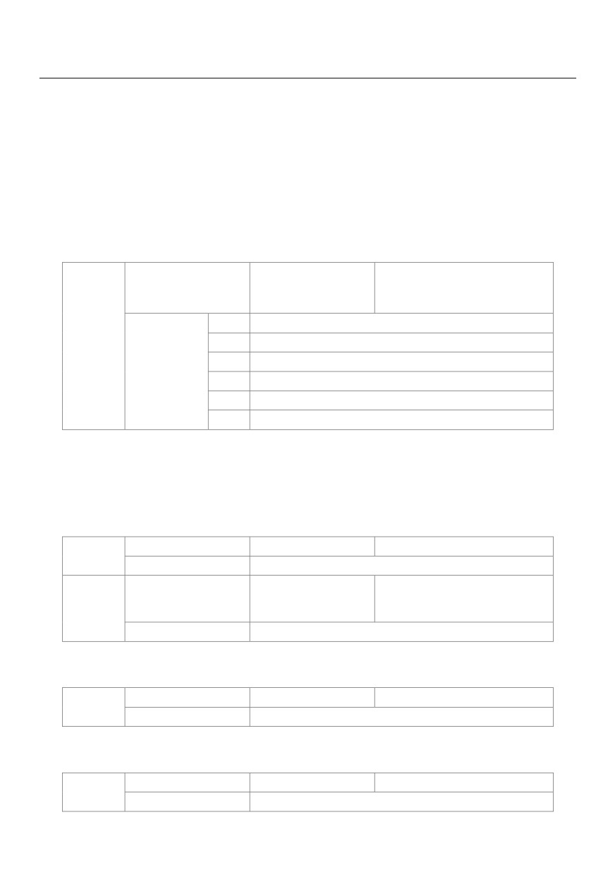
value of this parameter.
The output frequency of the HV580L can reach up to 3200 Hz. To take both frequency reference resolution
and frequency input range into consideration, you can set the number of decimal places for frequency
reference in P0-22.
If P0-22 is set to 1, the frequency reference resolution is 0.1 Hz. In this case, the setting range of P0-10 is 50.0
to 3200.0 Hz.
If P0-22 is set to 2, the frequency reference resolution is 0.01 Hz. In this case, the setting range of P0-10 is
50.00 to 320.00 Hz.
Source of frequency
Default
0
upper limit
0
Set by P0-12
P0-11
1
VS
2
AS
Setting Range
3
VS2
4
PULSE setting (X5)
5
Communication setting
It is used to set the source of the frequency upper limit, including digital setting (P0-12), AI, pulse setting or
communication setting. If the frequency upper limit is set by means of analog input, the analog input setting is
100% corresponding to P0-12.
For example, to avoid runaway in torque control mode in winding application, you can set the frequency upper
limit by means of analog input. When the AC drive reaches the upper limit, it will continue to run at this speed.
Frequency upper limit
Default
50.00Hz
P0-12
Setting Range
Frequency lower limit P0-14 ~maximum frequency P0-10
Frequency upper limit
Default
0.00Hz
P0-13
offset
Setting Range
0.00Hz ~maximum frequency P0-10
If the source of the frequency upper limit is analog input or pulse setting, the final frequency upper limit is
obtained by adding the offset in this parameter to the frequency upper limit set in P0-11
Frequency lower limit
Default
0.00Hz
P0-14
Setting Range
0.00Hz ~frequency upper limit P0-12
If the frequency reference is lower than the value of this parameter, the AC drive can stop, run at the
frequency lower limit, or run at zero speed, determined by P8-14.
Carrier frequency
Default
Model dependent
P0-15
Setting Range
0.5kHz ~ 16.0kHz
81
It is used to adjust the carrier frequency of the AC drive, helping to reduce the motor noise, avoiding the
resonance of the mechanical system, and reducing the leakage current to the earth and interference
generated by the AC drive.
If the carrier frequency is low, output current has high harmonics, and the power loss and temperature rise of
the motor increase.
If the carrier frequency is high, power loss and temperature rise of the motor declines.
However, the AC drive has an increase in power loss, temperature rise and interference.
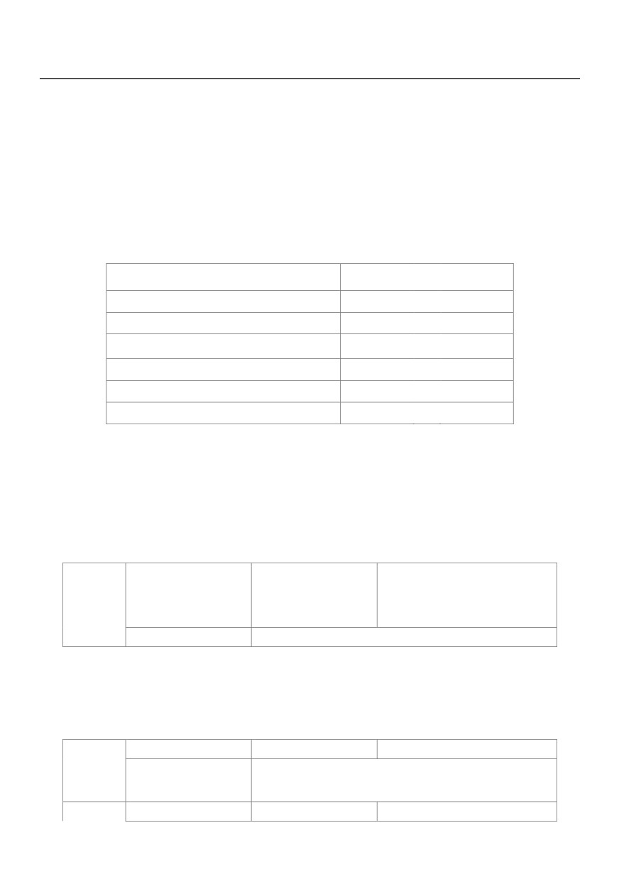
Adjusting the carrier frequency will exert influences on the aspects listed in the following table:
Carrier frequency
Low
→ High
Motor noise
Large
→ Small
Output current waveform
Bad
→ Good
Motor temperature rise
High
→ Low
AC drive temperature rise
Low
→ High
Leakage current
Small
→ Large
External radiation interference
Small
→ Large
The factory setting of carrier frequency varies with the AC drive power. If you need to modify the carrier
frequency, note that if the set carrier frequency is higher than factory setting, it will lead to an increase in
temperature rise of the AC drive's heatsink. In this case, you need to de-rate the AC drive. Otherwise, the AC
drive may overheat and alarm.
Carrier frequency
adjustment with
Default
1
P0-16
temperature
Setting Range
0: No
1: Yes
It is used to set whether the carrier frequency is adjusted based on the temperature. The AC drive
automatically reduces the carrier frequency when detecting that the heatsink temperature is high. The AC
drive resumes the carrier frequency to the set value when the heatsink temperature becomes normal. This
function reduces the overheat alarms.
Acceleration time 1
Default
Model dependent
P0-17
0.00s ~ 650.00s (P0-19=2)
Setting Range
0.0s ~ 6500.0s (P0-19=1)
P0-18
Deceleration time 1
Default
Model dependent
82
0.00s ~ 650.00s (P0-19=2)
Setting Range
0.0s ~ 6500.0s (P0-19=1)
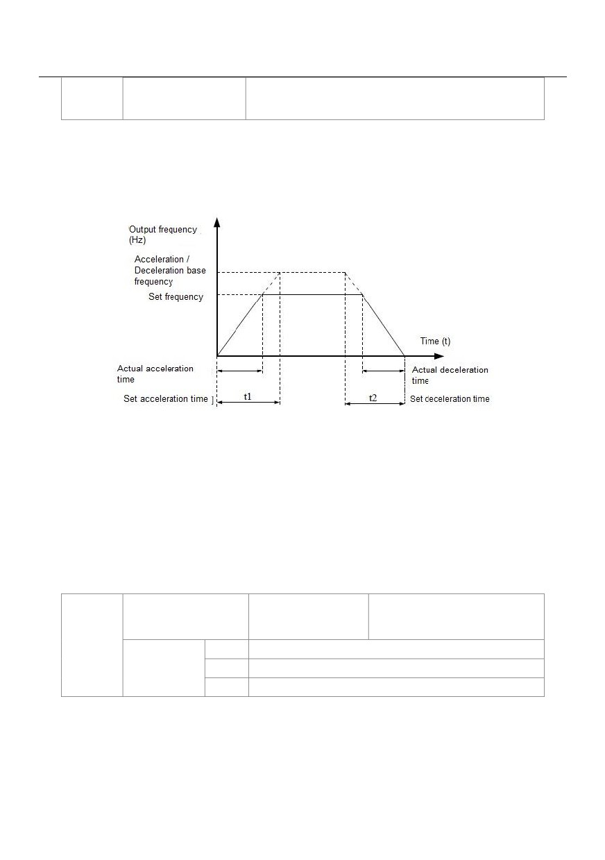
Acceleration time indicates the time required by the AC drive to accelerate from 0 Hz to
"Acceleration/Deceleration base frequency" (P0-25), that is, t1 in Figure 6-1.
Deceleration time indicates the time required by the AC drive to decelerate from
"Acceleration/Deceleration base frequency" (P0-25) to 0 Hz, that is, t2 in Figure 6-1.
Figure 6-1 Acceleration / Deceleration time
The HV580L provides totally four groups of acceleration/deceleration time for selection. You can perform
switchover by using a X terminal.
Group 1: P0-17, P0-18
Group 2: P8-03, P8-04
Group 3: P8-05, P8-06
Group 4: P8-07, P8-08
Acceleration/Deceleration
Default
1
time unit
P0-19
0
1s
Setting Range
1
0.1s
2
0.01s
To satisfy requirements of different applications, the HV580L provides three acceleration/deceleration time
units, 1s, 0.1s and 0.01s.
Note:
Modifying this parameter will make the displayed decimal places change and corresponding
83
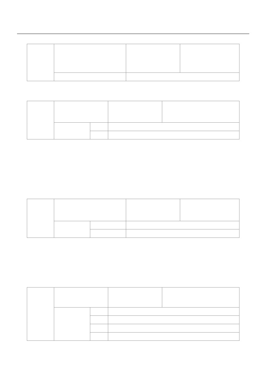
acceleration/deceleration time also change.
Frequency offset of auxiliary
frequency source for X and Y
Default
0.00Hz
P0-21
operation
Setting Range
0.00Hz ~maximum frequency P0-10
This parameter is valid only when the frequency source is set to "X and Y operation".
The final frequency is obtained by adding the frequency offset set in this parameter to the X and Y operation result.
Frequency reference
Default
2
resolution
P0-22
1
0.1Hz
Setting Range
2
0.01Hz
It is used to set the resolution of all frequency-related parameters.
If the resolution is 0.1 Hz, the HV580L can output up to 3200 Hz. If the resolution is 0.01 Hz, the HV580L can
output up to 600.00 Hz.
Note:
Modifying this parameter will make the decimal places of all frequency-related parameters change and
corresponding frequency values change.
Retentive of digital setting
Default
0
frequency upon power failure
P0-23
0
Not retentive
Setting Range
1
Retentive
This parameter is valid only when the frequency source is digital setting.
If P0-23 is set to 0, the digital setting frequency value resumes to the value of P0-08 (Preset frequency) after
the AC drive stops. The modification by using keys ▲ and ▼ or the terminal UP/DOWN function is cleared.
If P0-23 is set to 1, the digital setting frequency value is the set frequency at the moment when the AC drives
stops. The modification by using keys ▲ and ▼ or the terminal UP/DOWN function remains effective.
Motor parameter group
Default
0
selection
0
Motor parameter group 1
P0-24
1
Motor parameter group 2
Setting Range
2
Motor parameter group 3
3
Motor parameter group 4
The HV580L can drive four motors at different time. You can set the motor nameplate parameters respectively,
84
independent motor auto-tuning, different control modes, and parameters related to running performance
respectively for the four motors.
Motor parameter group 1 corresponds to groups P1 and P2. Motor parameter groups 2, 3 and 4 correspond to
groups A2, A3 and A4 respectively.
You can select the current motor parameter group by using P0-24 or perform switchover between the motor
parameter groups by means of a X terminal. If motor parameters selected by means of P0-24 conflict with
those selected by means of X terminal, the selection by X is preferred.
Acceleration/Deceleration
Default
0
time base frequency
P0-25
0
Maximum (P0-10)
Setting Range
1
Set frequency
2
100Hz
The acceleration/deceleration time indicates the time for the AC drive to increase from 0 Hz to the frequency
set in P0-25. Figure 6-1 shows the acceleration/deceleration time.
If this parameter is set to 1, the acceleration/deceleration time is related to the set frequency. If the set
frequency changes frequently, the motor's acceleration/deceleration also changes.
Base frequency for UP/DOWN
Default
0
modification during running
P0-26
0
Running frequency
Setting Range
1
Set frequency
This parameter is valid only when the frequency source is digital setting.
It is used to set the base frequency to be modified by using keys ▲ and ▼ or the terminal UP/DOWN function.
If the running frequency and set frequency are different, there will be a large difference between the AC drive's
performance during the acceleration/deceleration process.
Binding command source to
Default
000
frequency source
Unit’s digit
Binding operation panel command to frequency source
P0-27
0
No binding
Setting Range
1
Frequency source by digital setting
2
VS
3
AS
4
VS2
85
5
PULSE setting (X5)
6
Multi-reference
7
Simple PLC
8
PID
9
Communication setting
Binding terminal command to frequency source
Ten’s digit
(0-9, same as unit's digit)
Hundred’s
Binding communication command to frequency source
digit
(0-9, same as unit's digit)
It is used to bind the three running command sources with the nine frequency sources, facilitating to
implement synchronous switchover.
For details on the frequency sources, see the description of P0-03 (Main frequency source X selection).
Different running command sources can be bound to the same frequency source.
If a command source has a bound frequency source, the frequency source set in P0-03 to P0-07 no longer
takes effect when the command source is effective.
Serial communication protocol
Default
0
0
MODBUS protocol
P0-28
Setting Range
1
Profibus-DP bridge
2
CANopen bridge
The HV580L supports Modbus, PROFIBUS-DP bridge and CANopen bridge. Select a proper protocol based
on the actual requirements.
Group P1: Motor 1 Parameters
Motor type selection
Default
0
0
Common asynchronous motor
P1-00
Setting Range
1
Variable frequency asynchronous motor
2
Permanent magnetic synchronous motor
Rated motor power
Default
Model dependent
P1-01
Setting Range
0.1kW ~ 1000.0kW
Rated motor voltage
Default
Model dependent
P1-02
Setting Range
1V ~ 2000V
P1-03
Rated motor current
Default
Model dependent
86
0.01A ~ 655.35A( AC drive power <=55kW)
Setting Range
0.1A ~ 6553.5A( AC drive power >55kW)
Rated motor frequency
Default
Model dependent
P1-04
Setting Range
0.01Hz ~maximum frequency
Rated motor rotational
Default
Model dependent
P1-05
speed
Setting Range
1rpm ~ 65535rpm
Set the parameters according to the motor nameplate, no matter whether V/F control or vector control is adopted.
To achieve better V/F or vector control performance, motor auto-tuning is required. The motor auto-tuning
accuracy depends on the correct setting of motor nameplate parameters.
Stator resistance
Default
Model dependent
(asynchronous motor)
P1-06
~ 65.535Ω(AC drive power ≤ 55kW)
Setting Range
0.0001Ω
~ 6.5535Ω(AC drive power >55kW)
Rotor resistance
Default
Model dependent
(asynchronous motor)
P1-07
~ 65.535Ω(AC drive power ≤ 55kW)
Setting Range
~ 6.5535Ω(AC drive power >55kW)
Leakage inductive
reactance (asynchronous
Default
Model dependent
P1-08
motor)
0.01mH ~ 655.35mH(AC drive power ≤ 55kW)
Setting Range
0.001mH ~ 65.535mH(AC drive power >55kW)
Mutual inductive
Default
Model dependent
reactance
P1-09
0.1mH ~ 6553.5mH(AC drive power ≤ 55kW)
Setting Range
0.01mH ~ 655.35mH(AC drive power >55kW)
No-load current
P1-10
Default
Model dependent
(asynchronous motor)
87
0.01A ~ P1-03(AC drive power ≤ 55kW)
Setting Range
0.1A ~ P1-03(AC drive power >55kW)
The parameters in P1-06 to P-10 are asynchronous motor parameters. These parameters are unavailable on
the motor nameplate and are obtained by means of motor auto-tuning. Only P1-06 to P1-08 can be obtained
through static motor auto-tuning. Through complete motor auto-tuning, encoder phase sequence and current
loop PI can be obtained besides the parameters in P1-06 to P1-10.
Each time "Rated motor power" (P1-01) or "Rated motor voltage" (P1-02) is changed; the AC drive
automatically restores values of P1-06 to P1-10 to the parameter setting for the common standard Y series
asynchronous motor.
If it is impossible to perform motor auto-tuning onsite, manually input the values of these parameters
according to data provided by the motor manufacturer.
Stator resistance
Default
Model dependent
(synchronous motor)
P1-16
~ 65.535Ω(AC drive power ≤ 55kW)
Setting Range
~ 6.5535Ω(AC drive power >55kW)
Shaft D inductance
Default
Model dependent
(synchronous motor)
P1-17
0.01mH ~ 655.35mH(AC drive power ≤ 55kW)
Setting Range
0.001mH ~ 65.535mH(AC drive power >55kW)
Shaft Q inductance
Default
Model dependent
(synchronous motor)
P1-18
0.01mH ~ 655.35mH(AC drive power ≤ 55kW)
Setting Range
0.001mH ~ 65.535mH(AC drive power >55kW)
Back EMF
Default
Model dependent
P1-20
(synchronous motor)
Setting Range
0.1V ~ 6553.5V
P1-16 to P-20 is synchronous motor parameters. These parameters are unavailable on the nameplate of most
synchronous motors and can be obtained by means of "Synchronous motor no-load auto-tuning". Through
"Synchronous motor with-load auto-tuning", only the encoder phase sequence and installation angle can be
obtained.
Each time "Rated motor power" (P1-01) or "Rated motor voltage" (P1-02) is changed; the AC drive
automatically modifies the values of P1-16 to P1-20.
88
You can also directly set the parameters based on the data provided by the synchronous motor manufacturer.
Encoder pulses per revolution
Default
1024
P1-27
Setting Range
1 ~ 65535
This parameter is used to set the pulses per revolution (PPR) of ABZ or UVW incremental encoder. In CLVC
mode, the motor cannot run properly if this parameter is set incorrectly.
Encoder type
Default
0
0
ABZ incremental encoder
1
UVW incremental encoder
P1-28
Setting Range
2
Resolver
3
SIN/COS encoder
4
Wire-saving UVW encoder
The HV580L supports multiple types of encoder. Different PG cards are required for different types of encoder.
Select the appropriate PG card for the encoder used. Any of the five encoder types is applicable to
synchronous motor. Only ABZ incremental encoder and resolver are applicable to asynchronous motor.
After installation of the PG card is complete, set this parameter properly based on the actual condition.
Otherwise, the AC drive cannot run properly
A/B phase sequence of ABZ
Default
0
incremental encoder
P1-30
0
Forward
Setting Range
1
Reserve
This parameter is valid only for ABZ incremental encoder (P1-28 = 0) and is used to set the A/B phase
sequence of the ABZ incremental encoder
It is valid for both asynchronous motor and synchronous motor. The A/B phase sequence can be obtained
through "Asynchronous motor complete auto-tuning" or "Synchronous motor no-load auto-tuning".
Encoder installation angle
Default
0.0°
P1-31
Setting Range
0.0°~ 359.9°
This parameter is applicable only to synchronous motor. It is valid for ABZ incremental encoder, UVW
incremental encoder, resolver and wire-saving UVW encoder, but invalid for SIN/COS encoder.
It can be obtained through synchronous motor no-load auto-turning or with-load auto-tuning. After installation
of the synchronous motor is complete, the value of this parameter must be obtained by motor auto-tuning.
Otherwise, the motor cannot run properly.
89
U, V, W phase sequence of
Default
0
UVW
P1-32
0
Forward
Setting Range
1
Reverse
UVW encoder angle offset
Default
0.0°
P1-33
Setting Range
0.0°~ 359.9°
These two parameters are valid only when the UVW encoder is applied to a synchronous motor.
They can be obtained by synchronous motor no-load auto-tuning or with-load auto tuning. After installation of
the synchronous motor is complete, the values of these two parameters must be obtained by motor
auto-tuning. Otherwise, the motor cannot run properly.
Number of pole pairs of
Default
1
P1-34
resolver
Setting Range
1 ~ 65535
If a resolver is applied, set the number of pole pairs properly.
Encoder wire-break fault detection time
Default
0.0s
P1-36
Setting Range
0.0s: No action
0.1s ~ 10.0s
This parameter is used to set the time that a wire-break fault lasts. If it is set to 0.0s, the AC drive does not
detect the encoder wire-break fault.
If the duration of the encoder wire-break fault detected by the AC drive exceeds the time set in this parameter,
the AC drive reports Err20.
Auto-tuning selection
Default
0
0
No auto-tuning
1
Asynchronous motor static auto-tuning
P1-37
2
Asynchronous motor complete auto-tuning
Setting
3
Static complete parameter identification
11
Synchronous motor with-load auto-tuning
12
Synchronous motor no-load auto-tuning
0: No auto-tuning, auto-tuning is prohibited.
1: Asynchronous motor static auto-tuning
90
It is applicable to scenarios where complete auto-tuning cannot be performed because the asynchronous
motor cannot be disconnected from the load.
Before performing static auto-tuning, properly set the motor type and motor nameplate parameters of P1-00 to
P1-05 first. The AC drive will obtain parameters of P1-06 to P1-08 by static auto-tuning.
Action specification: Set this parameter to 1, and press the RUN key. Then, the AC drive starts static
auto-tuning.
2: Asynchronous motor complete auto-tuning
To perform this type of auto-tuning, ensure that the motor is disconnected from the load. During the process of
complete auto-tuning, the AC drive performs static auto-tuning first and then accelerates to 80% of the rated
motor frequency within the acceleration time set in P0-17. The AC drive keeps running for a certain period and
then decelerates to stop within deceleration time set in P0-18.
Before performing complete auto-tuning, properly set the motor type, motor nameplate parameters of P1-00 to
P1-05, "Encoder type" (P1-28) and "Encoder pulses per revolution" (P1-27) first.
The AC drive will obtain motor parameters of P1-06 to P1-10, "A/B phase sequence of ABZ incremental
encoder" (P1-30) and vector control current loop PI parameters of P2-13 to P2-16 by complete auto-tuning.
Action specification: Set this parameter to 2, and press the RUN key. Then, the AC drive starts complete auto
tuning.
3: Static complete parameter identification
Suitable for no encoder, motor under stationary state to complete motor parameter self learning (the motor
may be still slight shaking, need to pay attention to safety).
Before complete asynchronous machine static tuning, the motor type and motor nameplate parameter P1-00
~ P1-05 must be set properly. After complete asynchronous machine static tuning, frequency inverter can get
P1-06 ~ P1-10 five parameters
11: Synchronous motor with-load auto-tuning
It is applicable to scenarios where the synchronous motor cannot be disconnected from the load. During
with-load auto-tuning, the motor rotates at the speed of 10 PRM.
Before performing with-load auto-tuning, properly set the motor type and motor nameplate parameters of
P1-00 to P1-05 first.
By with-load auto-tuning, the AC drive obtains the initial position angle of the synchronous motor, which is a
necessary prerequisite of the motor's normal running.
Before the first use of the synchronous motor after installation, motor auto-tuning must be performed.
Action specification: Set this parameter to 11, and press the RUN key. Then, the AC drive starts with-load
91
auto-tuning.
12: Synchronous motor no-load auto-tuning
If the synchronous motor can be disconnected from the load, no-load auto-tuning is recommended, which will
achieve better running performance compared with with-load auto-tuning.
During the process of no-load auto-tuning, the AC drive performs with-load auto-tuning first and then
accelerates to 80% of the rated motor frequency within the acceleration time set in P0-17. The AC drive keeps
running for a certain period and then decelerates to stop within the deceleration time set in P0-18
Before performing no-load auto-tuning, properly set the motor type, motor nameplate parameters of P1-00 to
P1-05, "Encoder type" (P1-28) and "Encoder pulses per revolution" (P1-27) and "Number of pole pairs of
resolver" (P1-34) first.
The AC drive will obtain motor parameters of P1-16 to P1-20, encoder related parameters of P1-30 to P1-33
and vector control current loop PI parameters of P2-13 to P2-16 by no-load auto-tuning.
Action specification: Set this parameter to 12, and press the RUN key. Then, the AC drive starts no-load
auto-tuning.
Note: Motor auto-tuning can be performed only in operation panel mode.
Group P2: Vector Control Parameters
Group P2 is valid for vector control, and invalid for V/F control.
Speed loop proportional gain 1
Default
30
P2-00
Setting Range
1 ~ 100
Speed loop integral time 1
Default
0.50s
P2-01
Setting Range
0.01s ~ 10.00s
Switchover frequency 1
Default
5.00Hz
P2-02
Setting Range
0.00 ~ P2-05
Speed loop proportional gain 2
Default
20
P2-03
Setting Range
0 ~ 100
Speed loop integral time 2
Default
1.00s
P2-04
Setting Range
0.01s ~ 10.00s
Switchover frequency 2
Default
10.00Hz
P2-05
Setting Range
P2-02 ~maximum output frequency
Speed loop PI parameters vary with running frequencies of the AC drive.
• If the running frequency is less than or equal to "Switchover frequency 1" (P2-02), the speed loop PI
parameters are P2-00 and P2-01.
• If the running frequency is equal to or greater than "Switchover frequency 2" (P2-05), the speed loop PI
92