HV580L Series Frequency Inverter. User Manual (Version: 3.1.14) - page 1
User Manual
HNC Electric Limited
Contents
Contents
2
Chapter 1 Safety Information and Precautions
4
1.1 Safety Information
4
1.2 General Precautions
7
Chapter 2 Product Information
10
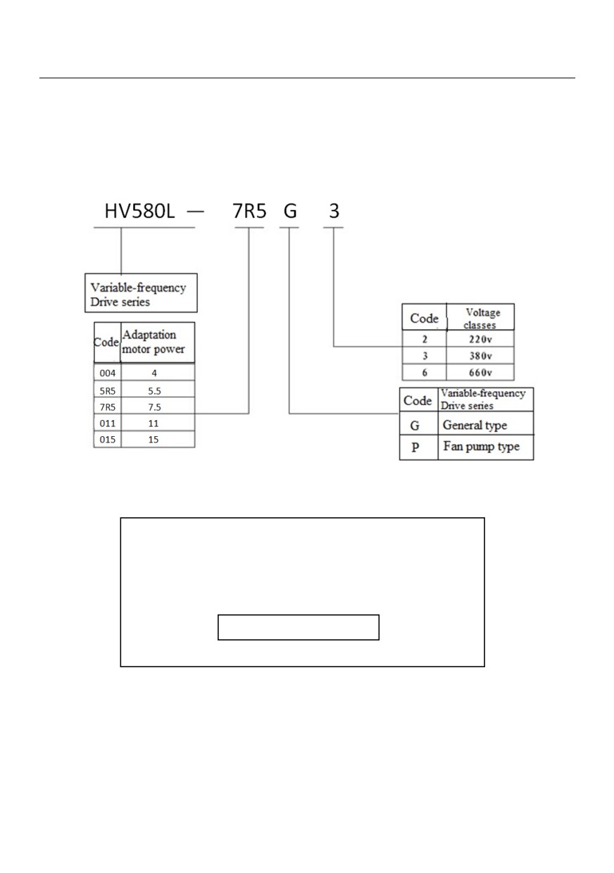
2.1 Designation Rules and Nameplate of the HV580L
10
2.2 Nameplates
10
2.3 HV580L Variable-frequency Drive series
11
2.4 Technical specifications
12
2.5 Variable-frequency Drive rated output current
16
Chapter 3 Mechanical and Electrical Installation
17
3.1 Mechanical Installation
17
3.2 Electrical Installation
21
Chapter 4 Operation, Display and Application Examples
27
4.1 Operation Panel
27
4.2 Description of keys on the operation panel
29
Chapter 5 Function Code Table
31
Chapter 6 Description of Function Codes
75
Group P0: Basic Parameters
75
Group P1: Motor 1 Parameters
86
Group P2: Vector Control Parameters
92
Group P3: V/F Control Parameters
96
Group P4: Input Terminals
102
Group P5: Output Terminals
116
Group P6 Start/Stop Control
122
Group P7 Operation Panel and Display
128
Group P8 Auxiliary Functions
131
2
Group P9 Fault and Protection
144
Group PA: Process Control PID Function
154
Group PB: Swing Frequency, Fixed Length and Count
161
Group PC: Multi-Reference and Simple PLC Function
164
Group PD: Communication parameters
170
Group PP: User’s password
170
Group A0: Torque Control and Restricting Parameters
172
Group C Monitor
174
Chapter 7 Maintenance and Troubleshooting
177
7.1 Routine Repair and Maintenance of the HV580L
177
7.2 Warranty Agreement
178
7.3 Faults and Solutions
179
7.4 Common Faults and Solutions
187
Appendix A:RS-485 communication expansion card instruction
191
AppendixB:HV580L Modbus communication
192
Warranty Agreement
204
3
Chapter 1 Safety Information and Precautions
In this manual, the notices are graded based on the degree of danger:
•
DANGER indicates that failure to comply with the notice will result in severe personal injury or even death.
•
WARNING indicates that failure to comply with the notice will result in personal injury or property damage.
Read this manual carefully so that you have a thorough understanding. Installation, commissioning or
maintenance may be performed in conjunction with this chapter. HNC Electric will assume no liability or
responsibility for any injury or loss caused by improper operation.
1.1 Safety Information
Use
Safety
Precautions
Stage
Grade
• Do not install the equipment if you find water seepage, component missing or
DANGER
damage upon unpacking.
• Do not install the equipment if the packing list does not conform to the product you.
Before
• Handle the equipment with care during transportation to prevent damage to the equipment.
installation
• Do not use the equipment if any component is damaged or missing.
Failure to comply will result in personal injury.
WARNING
• Do not touch the components with your hands. Failure to comply will result in static
electricity damage.
• Install the equipment on incombustible objects such as metal, and keep it away
During
from combustible materials. Failure to comply may result in a fire.
DANGER
installation
• Do not loosen the fixed screws of the components, especially the screws with red
mark.
4
• Do not drop wire end or screw into the AC drive. Failure to comply will result in
damage to the AC drive.
WARNING
• Install the AC drive in places free of vibration and direct sunlight.
• When two AC drives are laid in the same cabinet, arrange the installation positions
properly to ensure the cooling effect.
• Wiring must be performed only by qualified personnel under instructions described
in this manual. Failure to comply may result in unexpected accidents.
• A circuit breaker must be used to isolate the power supply and the AC drive. Failure
to comply may result in a fire.
DANGER
• Ensure that the power supply is cut off be ore wiring. Failure to comply may result in
electric shock.
• Tie the AC drive to ground properly by standard. Failure to comply may result in
electric shock.
At wiring
• Never connect the power cables to the output terminals (U, V, W) of the AC drive.
Pay attention to the marks of the wiring terminals and ensure correct wiring. Failure
to comply will result in damage to the AC drive.
• Never connect the braking resistor between the DC bus terminals (+) and (-).Failure
WARNING
to comply may result in a fire.
• Use wire sizes recommended in the manual. Failure to comply may result in
accidents.
• Use a shielded cable for the encoder, and ensure that the shielding layer is reliably
grounded.
• Check that the following requirements are met:
- The voltage class of the power supply is consistent with the rated voltage class of
the AC drive.
- The input terminals (R, S, T) and output terminals (U, V, W) are properly
Before
connected.
DANGER
power-on
- No short-circuit exists in the peripheral circuit.
-The wiring is secured.
Failure to comply will result in damage to the AC drive
• Do not perform the voltage resistance test on any part of the AC drive because
such test has been done in the factory. Failure to comply will result in accidents.
5
• Cover the AC drive properly before power-on to prevent electric shock.
WARNING
• All peripheral devices must be connected properly under the instructions described
in this manual. Failure to comply will result in accidents.
• Do not open the AC drive's cover after power-on. Failure to comply may result in
electric shock.
DANGER
• Do not touch any I/O terminal of the AC drive. Failure to comply may result in
electric shock.
After
• Do not touch the rotating part of the motor during the motor auto-tuning or running.
power-on
Failure to comply will result in accidents.
WARNING
• Do not change the default settings of the AC drive. Failure to comply will result in
damage to the AC drive.
• Do not touch the fan or the discharging resistor to check the temperature. Failure to
comply will result in personal burnt.
DANGER
• Signal detection must be performed only by qualified personnel during operation.
Failure to comply will result in personal injury or damage to the AC drive.
During
• Avoid objects falling into the AC drive when it is running. Failure to comply will
operation
result in damage to the AC drive.
WARNING
• Do not start/stop the AC drive by turning the contactor ON/OFF. Failure to comply
will result in damage to the AC drive.
6
• Repair or maintenance of the AC drive may be performed only by qualified
personnel. Failure to comply will result in personal injury or damage to the AC drive.
• Do not repair or maintain the AC drive at power-on. Failure to comply will result in
electric shock.
• Repair or maintain the AC drive only ten minutes after the AC drive is powered off.
This allows for the residual voltage in the capacitor to discharge to a safe value.
Failure to comply will result in personal injury.
During
DANGER
• Ensure that the AC drive is disconnected from all power supplies before starting
maintenance
repair or maintenance on the AC drive.
• Set and check the parameters again after the AC drive is replaced.
• All the pluggable components must be plugged or removed only after power-off.
• The rotating motor generally feeds back power to the AC drive.
As a result, the AC drive is still charged even if the motor stops, and the power
supply is cut off. Thus ensure that the AC drive is disconnected from the motor
before starting repair or maintenance on the AC drive.
1.2 General Precautions
1) Motor insulation test
Perform the insulation test when the motor is used for the first time, or when it is reused after being stored for a
long time, or in a regular check-up, in order to prevent the poor insulation of motor windings from damaging
the AC drive. The motor must be disconnected from the AC drive during the insulation test. A 500-V
mega-Ohm meter is recommended for the test. The insulation resistance must not be less than 5 MΩ.
2) Thermal protection of motor
If the rated capacity of the motor selected does not match that of the AC drive, especially when the AC drive's
rated power is greater than the motor's, adjust the motor protection parameters on the operation panel of the
AC drive or install a thermal relay in the motor circuit for protection.
3) Running at over 50 Hz
The AC drive provides frequency output of 0 to 3200 Hz (Up to 300 Hz is supported if the AC drive runs in
CLVC and SFVC mode). If the AC drive is required to run at over 50 Hz, consider the capacity of the machine.
4) Vibration of mechanical device
The AC drive may encounter the mechanical resonance point at some output frequencies, which can be
avoided by setting the skip frequency.
7
5) Motor heat and noise
The output of the AC drive is pulse width modulation (PWM) wave with certain harmonic frequencies, and
therefore, the motor temperature, noise, and vibration are slightly greater than those when the AC drive runs
at power frequency (50 Hz).
6) When external voltage is out of rated voltage range
The AC drive must not be used outside the allowable voltage range specified in this manual. Otherwise, the AC
drive's components may be damaged. If required, use a corresponding voltage step-up or step-down device.
7) Contactor at the I/O terminal of the AC drive
When a contactor is installed between the input side of the AC drive and the power supply, the AC drive must
not be started or stopped by switching the contactor on or off. If the AC drive has to be operated by the
contactor, ensure that the time interval between switching is at least one hour since frequent charge and
discharge will shorten the service life of the capacitor inside the AC drive.
When a contactor is installed between the output side of the AC drive and the motor, do not turn off the
contactor when the AC drive is active. Otherwise, modules inside the AC drive may be damaged.
8) When external voltage is out of rated voltage range
The AC drive must not be used outside the allowable voltage range specified in this manual. Otherwise, the AC
drive's components may be damaged. If required, use a corresponding voltage step-up or step-down device.
9) Prohibition of three-phase input changed into two-phase input
Do not change the three-phase input of the AC drive into two-phase input. Otherwise, a fault will result or the
AC drive will be damaged.
10) Lightning shock protection
This series of frequency converter is equipped with a lightning over current protection device, for induction
lightning has certain ability of self-protection, but for frequent lightning place customers should also be adding
lightning protection devices in inverter front.
11) Altitude and de-rating
In places where the altitude is above 1000 m and the cooling effect reduces due to thin air, it is necessary to
de-rate the AC drive. Contact HNC Electric for technical support.
12) Some special usages
If wiring that is not described in this manual such as common DC bus is applied, contact the agent or HNC
Electric for technical support.
13) Disposal
The electrolytic capacitors on the main circuits and PCB may explode when they are burnt. Poisonous gas is
8
generated when the plastic parts are burnt. Treat them as ordinary industrial waste
14) Adaptable Motor
• The standard adaptable motor is adaptable four-pole squirrel-cage asynchronous induction motor or PMSM.
For other types of motor, select a proper AC drive according to the rated motor current.
• The cooling fan and rotor shaft of non-variable-frequency motor are coaxial, which results in reduced cooling
effect when the rotational speed declines. If variable speed is required, add a more powerful fan or replace it
with variable-frequency motor in applications where the motor overheats easily.
• The standard parameters of the adaptable motor have been configured inside the AC drive. It is still
necessary to perform motor auto-tuning or modify the default values based on actual conditions. Otherwise,
the running result and protection performance will be affected.
• The AC drive may alarm or even be damaged when short-circuit exists on cables or inside the motor.
Therefore, perform insulation short-circuit test when the motor and cables are newly installed or during routine
maintenance. During the test, make sure that the AC drive is disconnected from the tested parts.
9
Chapter 2 Product Information
2.1 Designation Rules and Nameplate of the HV580L
2.2 Nameplates
MODEL: HV580L-7R5G3
POWER:
7.5KW
INPUT:
3PH AC380V 20.5A 50Hz/60Hz
OUTPUT:
3PH AC 0~380V 17A 0~300Hz
S/N:
Bar code
HNC Electric Limited
10
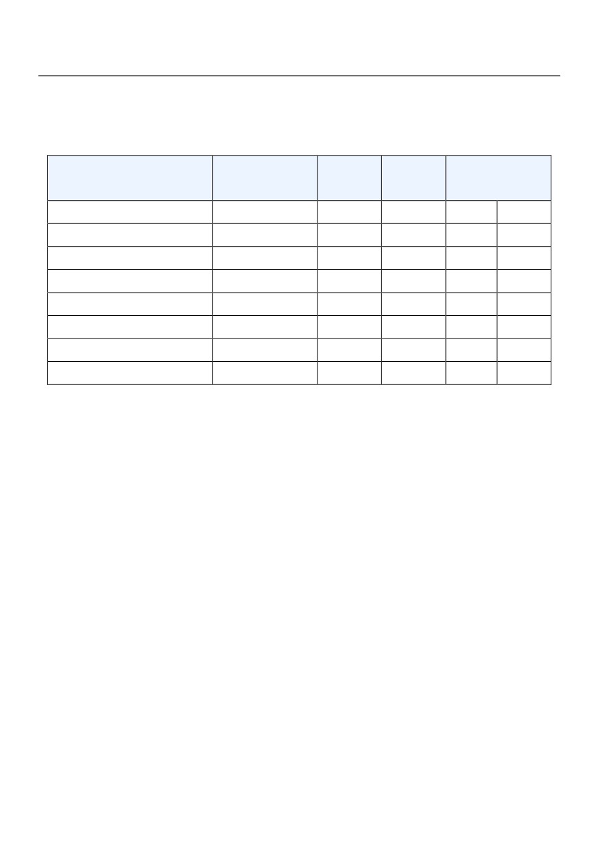
2.3 HV580L Variable-frequency Drive series
Figure 2-1 HV 580L Inverter model and technical data
Input
Output
Adapter motor
Variable frequency Drive type
Voltage V
Current A
current A
Kw
HP
HV580L-004G3
380V,50/60Hz
10.5
8.5
4
5
HV580L-5R5G3
380V,50/60Hz
15.5
13
5.5
7.5
HV580L-7R5G3
380V,50/60Hz
21
16
7.5
10
HV580L-7R5G3-A
380V,50/60Hz
21
16
7.5
10
HV580L-009G3
380V,50/60Hz
21
16
7.5
10
HV580L-011G3
380V,50/60Hz
27.6
25
11
15
HV580L-015G3
380V,50/60Hz
37.1
32
15
20
HV580L-018G3
380V,50/60Hz
41.9
38
18.5
25
11
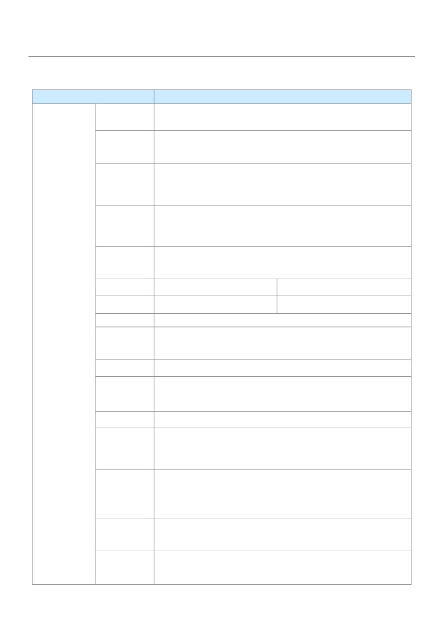
2.4 Technical specifications
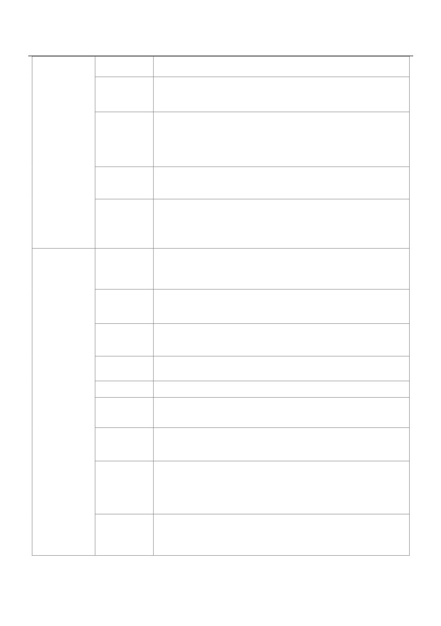
Figure 2-2 Technical specifications of the HV580L
Item
Specifications
Maximum
• Vector control: 0-300 Hz• V/F control: 0-320 Hz
frequency
Carrier
0.5-16 kHz
Frequency
The carrier frequency is automatically adjusted based on the load features.
Input frequency
Digital setting: 0.01 Hz
Resolution
Analog setting: maximum frequency x 0.025%
• Sensorless flux vector control (SFVC)
Control mode
• Closed-loop vector control (CLVC)
• Voltage/Frequency (V/F) control
• G type: 0.5 Hz/150% (SFVC); 0 Hz/180% (CLVC)
Startup torque
• P type: 0.5 Hz/100%
Speed range
1:100 (SVC)
1:1000 (FVC)
Speed stability
±0.5% (SVC)
±0.02% (FVC)
Standard
Torque control
±5% (FVC)
functions
Overload
• G type: 60sor 150% of the rated current, 3s for 180% of the rated current
capacity
• P type: 60s for 120% of the rated current, 3s for 150% of the rated current
Torque boost
• Fixed boost• Customized boost 0.1%-30.0%
• Straight-line V/F curve• Multi-point V/F curve
V/F curve
• N-power V/F curve (1.2-power, 1.4-power, 1.6-power,1.8-power,square)
V/F separation
Two types: complete separation; half separation
• Straight-line ramp• S-curve ramp
Ramp mode
Four groups of acceleration/deceleration time with the range of 0.0-6500.0s
DC braking frequency: 0.00 Hz to maximum frequency
DC braking
Braking time: 0.0-36.0s
Braking action current value: 0.0%-100.0%
JOG frequency range: 0.00-50.00 Hz
JOG control
JOG acceleration/deceleration time: 0.0-6500.0s
Onboard
It implements up to 16 speeds via the simple PLC function or combination
multiple preset
of X terminal states.
12
Onboard PID
It realizes process-controlled closed loop control system easily.
Auto voltage
It can keep constant output voltage automatically when the mains voltage
regulation
changes.
The current and voltage are limited automatically during the running
Over voltage/
Over current
process so as to avoid frequent tripping due to over voltage/over current.
stall Control
Fast current
Minimizing over-current fault protect the normal operation of the inverter
limiting function
It can limit the torque automatically and prevent frequent over current
Torque limit and
tripping during the running process.
control
Torque control can be implemented in the CLVC mode.
High
Control of asynchronous motor and synchronous motor are implemented
performance
through the high-performance current vector control technology.
Power dip ride
The load feedback energy compensates the voltage reduction so that the
Through
AC drive can continue to run for a short time.
Rapid current
It helps to avoid frequent over current faults of the AC drive.
limit
Virtual I/Os
Five groups of virtual DI/Dos can realize simple logic control.
Timing control
Time range: 0.0-6500.0 minutes
Individualized
Multi-motor
functions
Four motors can be switched over via four groups of motor parameters.
switchover
Multiple
It supports communication via Modbus -RTU, PROFIBUSDP, CAN link
communication
and CAN open.
Motor overheat
The optional I/O extension card enables AI3 to receive the motor
Protection
temperature sensor input (PT100, PT1000) so as to realize motor
overheat protection.
Multiple encoderIt supports various encoders such as differential encoder, open-collector
Types
encoder, resolver, UVW encoder, and SIN/COS encoder.
13
Item
Specifications
Running
• Operation panel • Control terminals • Serial communication port
command source
You can perform switchover between these sources in various ways.
There are a total of 10 frequency sources, such as digital setting, analog
voltage setting, analog current setting, pulse setting and serial
Frequency source
communication port setting.
You can perform switchover between these sources in various ways.
Auxiliary
There are ten auxiliary frequency sources. It can implement fine tuning of
frequency source
auxiliary frequency and frequency synthesis.
RUN
Standard:
5 digital input (X) terminals, one of which supports up to
100 kHz high-speed pulse input
2 analog input (AI) terminals, one of which only supports
0-10 V voltage input and the other supports 0-10 V voltage
Input terminal
input or 4-20 m A current input
Expanding capacity:
5 X terminals(one of which supports IGBT enable function)
1 AI terminal that supports -10-10 V voltage input and also
supports PT100\PT1000
14
Standard
1 high-speed pulse output terminal (open-collector) that
supports 0-100 kHz square wave signal output
1 digital output (DO) terminal
1 relay output terminal
1 analog output (AO) terminal that supports 0-20 m A
Output terminal
current output or 0-10 V voltage output
Expanding capacity:
1 DO terminal
1 relay output terminal
1 AO terminal that supports 0-20 m A current output or 0-10
V voltage output
Item
Specifications
Item
LED display
It displays the parameters.
LCD displaying
Optional parts, Chinese/English Prompt action content
Parameters of the
Achieved through the LCD operation panel option parameters of rapid
Display and
copy
replication
operation on
the operation
Key locking and
It can lock the keys partially or completely and define the function range of
panel
function selection
some keys so as to prevent mis-function.
Motor short-circuit detection at power-on, input/output phase loss
Protection mode
protection, over current protection, over voltage protection, under voltage
protection, overheat protection and overload protection
Installation
Indoor, free from direct sunlight, dust, corrosive gas, combustible gas, oil
Location
smoke, vapour, drip or salt.
Altitude
Lower than 1000 m
Environment
Ambient
-10°C to +40°C (de-rated if the ambient temperature is between 40°C and
Temperature
50°C)
Humidity
Less than 95%RH, without condensing
15
Vibration
Less than 5.9 m/s2 (0.6 g)
Storage Temperature- 20℃ ~ + 60℃
IP level
IP20
Pollution degree
PD2
Power distribution
TN , TT
System
2.5 Variable-frequency Drive rated output current
Figure 2-3 Variable-frequency Drive rated output current
Input voltage
220V
380V
660V
1140V
Rated power
Rated output current (A)
4
-
8.5
-
-
5.5
-
13
-
-
7.5
-
16
-
-
11
-
25
-
-
15
-
32
-
-
18.5
-
38
-
-
16
Chapter 3 Mechanical and Electrical Installation
3.1 Mechanical Installation
3.1.1 Installation Environment Requirements
1. Ambient temperature -10℃~40℃,Well ventilated or indoor Spaces with ventilation devices, more than
40 ℃ derating use. Avoid vibration, direct sunlight, away from heat source.
2. AC drives can install where altitude 1000 m below the output rated power, when more than 1000 m altitude
need derating use, specific derating range, please contact the company.
3. Avoid high temperature high humidity, the humidity is less than 90% RH (Non-condensate).
4. Apart from the oil, salt and corrosive gas. To prevent water, steam, dust, lint, metal powder.
5. Prevent electromagnetic interference, away from the interference sources.
6. It is prohibited to use in flammable, explosive gas, liquid or solid dangerous environment.
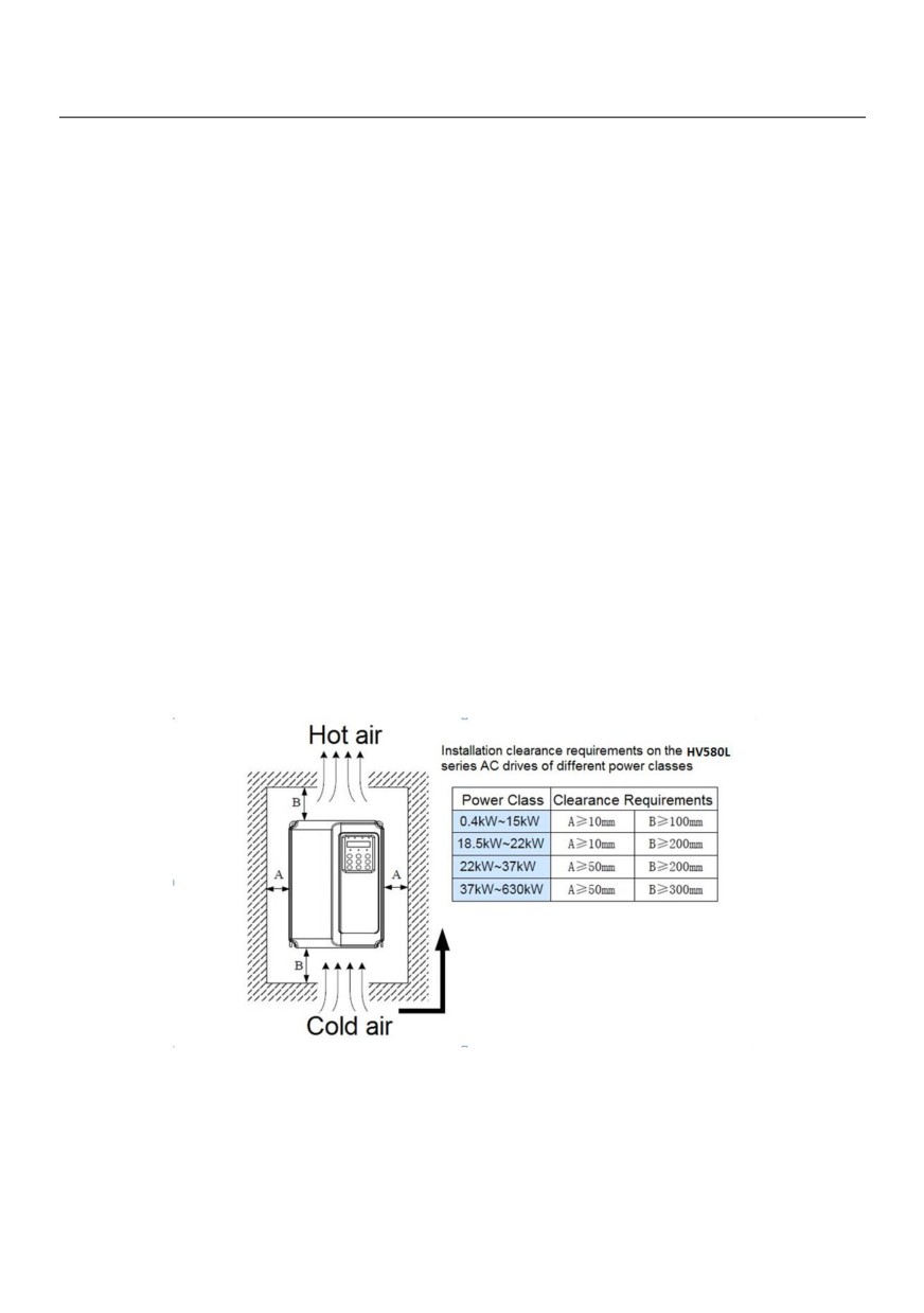
3.1.2 Installation Clearance Requirements
The clearance that needs to be reserved varies with the power class of the HV580L, as shown in the following
figure.
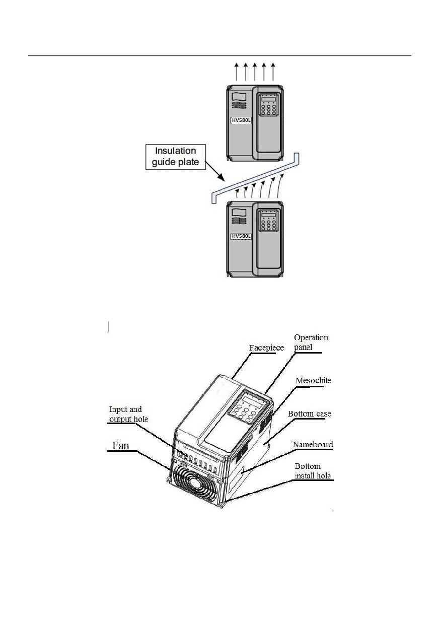
The HV580L series AC drive dissipates heat from the bottom to the top. When multiple AC drives are required
to work together, install them side by side.
For application installing multiple AC drives, if one row of AC drives need to be installed above another row,
install an insulation guide plate to prevent AC drives in the lower row from heating those in the upper row and
causing faults.
17
3.1.3 Mounting dimension
1)Online example
Figure 3-1 HV580L series online example
18
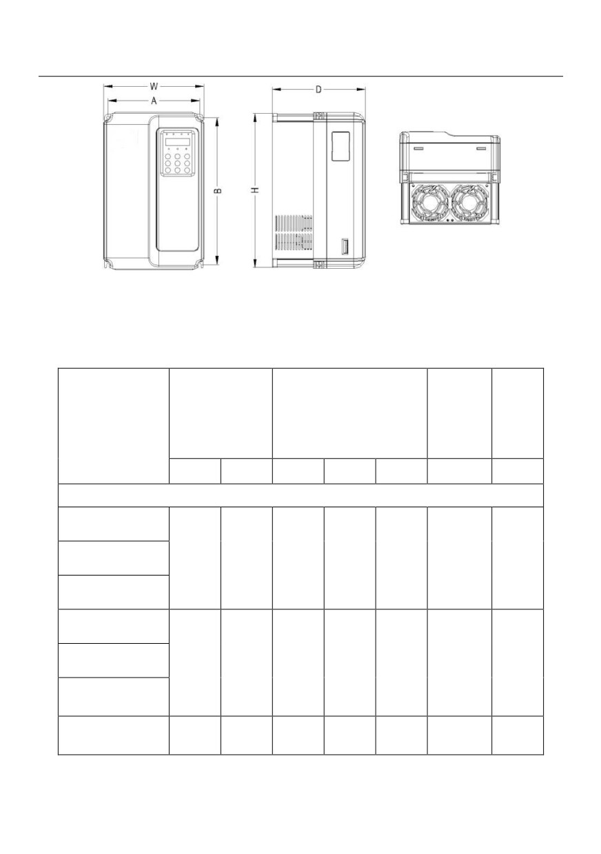
Figure 3-2 HV580L series Plastic structure shape dimension and installation dimension sketch
2)HV580L series VFD Mounting dimension and Mounting position size(mm)
3-1 Exterior and Mounting position size
Mounting
Mounting
External dimension
position
Weight
VFD type
position mm
mm
diameter
Kg
mm
A
B
H
W
D
Three phase 380V
HV580L-004G3
HV580L-5R5G3
148
236
248
150
183
ф5.0
2.5
HV580L-7R5G3
HV580L-7R5G3-A
HV580L-011G3
190
305
322
208
192
ф6.0
6.5
HV580L-015G3
HV580L-018G3
235
447
437
286
220
Ф7.0
17
19
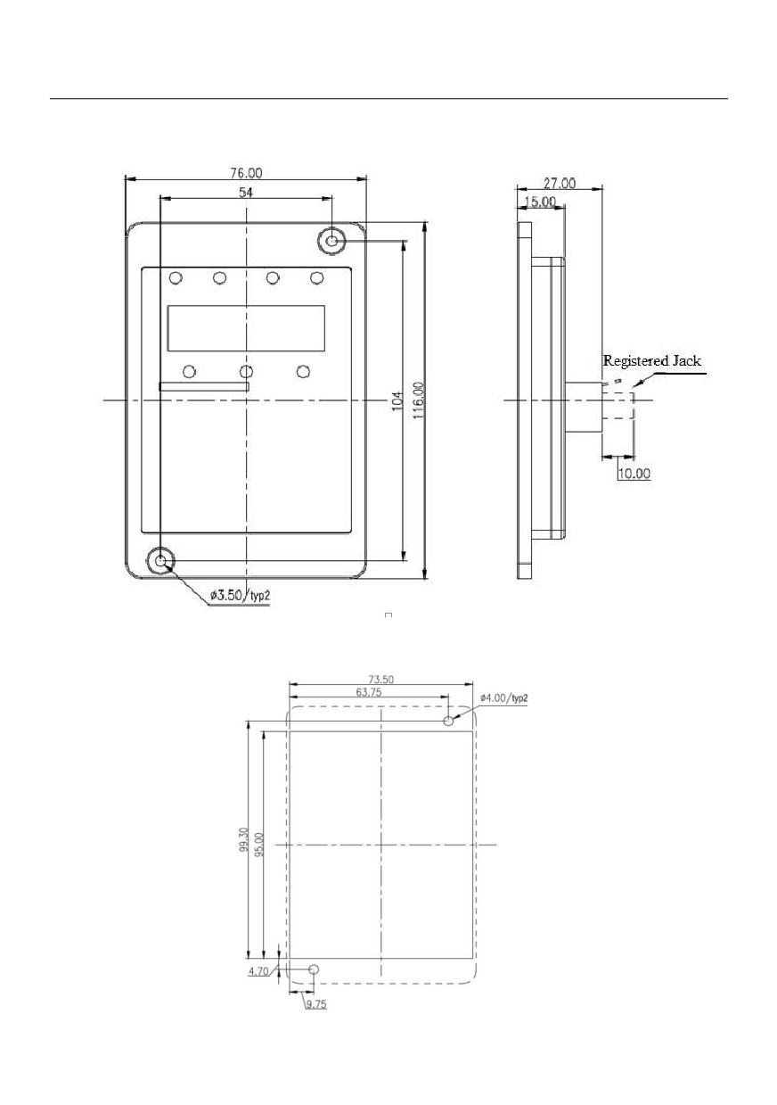
3)Irfpa keyboard installation dimensions
Figure 3-3 Irfpa keyboard installation dimensions
20
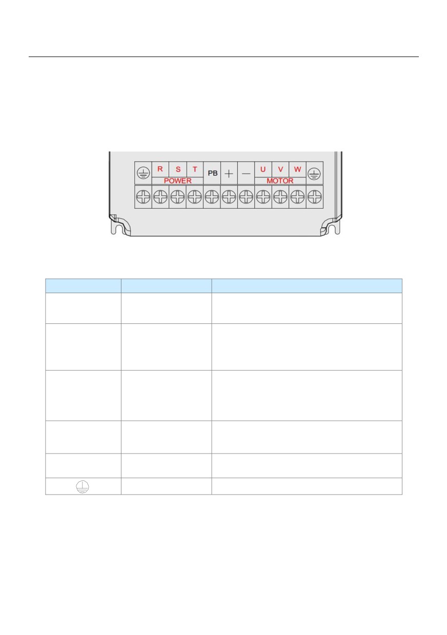
Figure 3-4 Irfpa keyboard installation hole size
3.2 Electrical Installation
3.2.1 Description of Main Circuit Terminals
Description of Main Circuit Terminals of Three-phase AC drive:
Figure 3-5 HV580L Inverter main circuit terminal distribution
3-2 Description of Main Circuit Terminals of Three-phase AC drive
Terminal
Name
Description
R、S、T
Three-phase power
Connect to the three-phase AC power supply
supply
(+)、(-)
Positive and negative
Common DC bus input point
terminals of DC bus
Connect the external braking unit to the AC drive of
37kW and above (220 V) and 18.5 kW and above.
(+)、PB
Connecting terminals of
Connect to the braking resistor for the AC drive of 30
braking resistor
kW and below (220 V) and 15 kW and below
(other voltage classes).
P、(+)
Connecting terminals of
Connect to an external reactor.
external reactor
U、V、W
AC drive output terminals
Connect to a three-phase motor.
Grounding terminal
Must be grounded.
3.2.2 Precautions on the Wiring:
1) Power input terminals L1, L2 or R, S, T:
● The cable connection on the input side of the AC drive has no phase sequence requirement.
● The specification and installation method of external power cables must comply with the local safety
regulations and related IEC standards.
2) DC bus terminals (+), (-):
21
● Terminals (+) and (-) of DC bus have residual voltage after the AC drive is switched off. After indicator
CHARGE goes off, wait at least 10 minutes before touching the equipment Otherwise, you may get electric
shock.
● Connecting external braking components for the AC drive of 18.5 kW and above (220 V) and 37 kW and
above (other voltage classes), do not reverse poles (+) and (-). Otherwise, it may damage the AC drive and
even cause a fire.
● The cable length of the braking unit shall be no longer than 10 m. Use twisted pair wire or pair wires for
parallel connection.
● Do not connect the braking resistor directly to the DC bus. Otherwise, it may damage the AC drive and even
cause fire.
3) Braking resistor connecting terminals (+), PB:
● 30kW and above (220 V) and 15 kW and the connecting terminals of the braking resistor are effective only
for the AC configured with the built-in braking unit.
● The cable length of the braking resistor shall be less than 5 m. Otherwise, it may damage the AC drive.
4)External reactor connecting terminals P, (+):
● For the AC drive of 37 kW and above (220 V) and 75 kW and above (other voltage classes), remove the
jumper bar across terminals P and (+) and install the reactor between the two terminals.
5) AC drive output terminals U, V, W:
● The specification and installation method of external power cables must comply with the local safety
regulations and related IEC standards.
● The capacitor or surge absorber cannot be connected to the output side of the AC drive. Otherwise, it may
cause frequent AC drive fault or even damage the AC drive.
● If the motor cable is too long, electrical resonance will be generated due to the impact of distributed
capacitance. This will damage the motor insulation or generate higher leakage current, causing the AC drive
to trip in over current protection. If the motor cable is greater than 100 m long, an AC output reactor must be
installed close to the AC drive.
6) Terminal PE:
● This terminal must be reliably connected to the main earthing conductor, ground wire resistance must be
less than 0.1Ω. Otherwise, it may mal-function or even damage to the AC drive.
● Do not connect
the earthing terminal to the neutral conductor of the power supply.
● The impedance of the PE conductor must be able to withstand the large short circuit current that may arise
when a fault occurs.
22
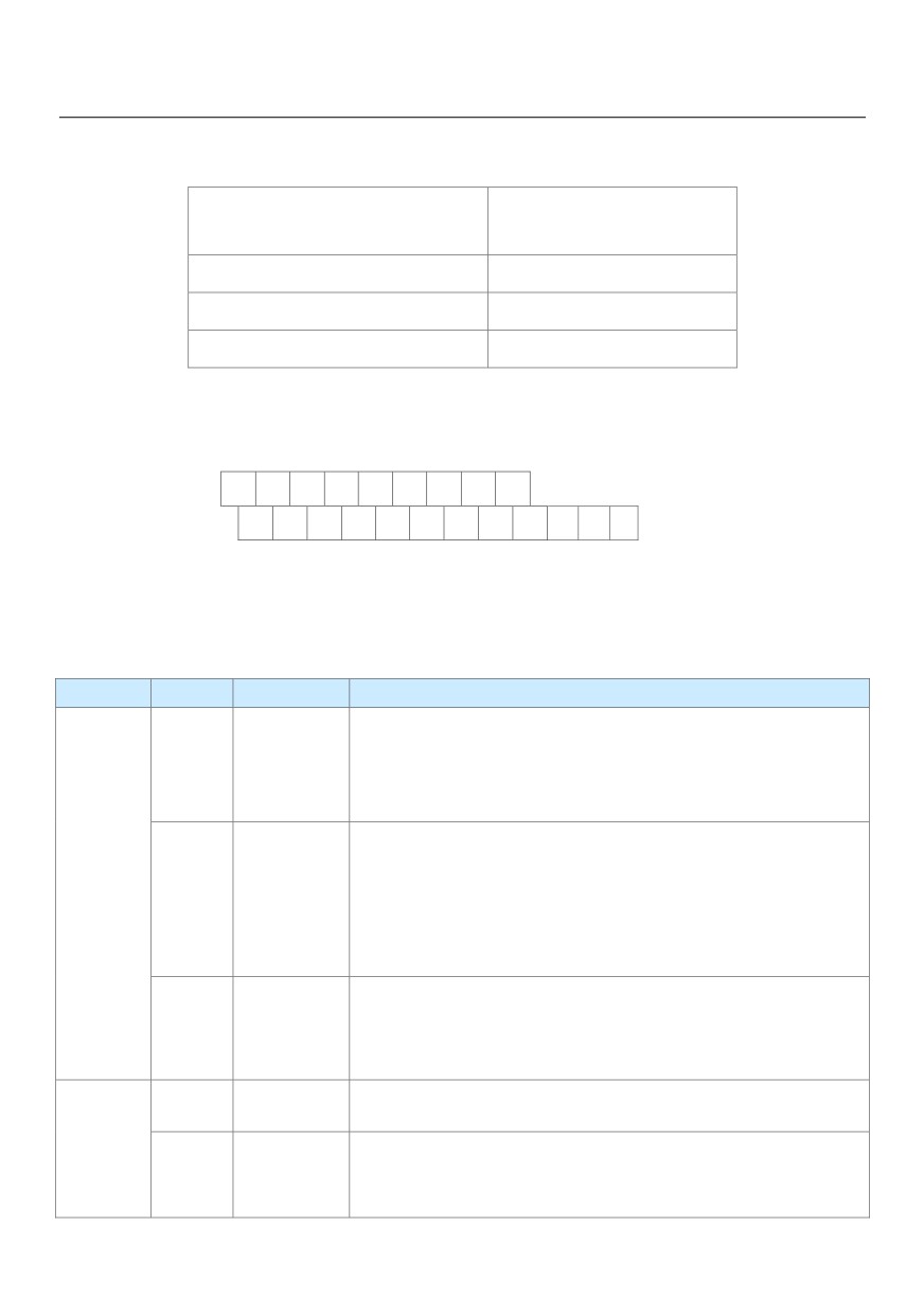
● Select the size of the PE conductor according to the following table:
Table 3-3 Grounding conductor size table
Cross-sectional Area of a
Min. Cross-sectional Area of
Phase Conductor (S)
Protective Conductor (Sp)
S ≤ 16mm2
S
16mm2 < S ≤ 35mm2
16mm2
35mm2 < S
S/2
● You must use a yellow/green cable as the PE conductor.
3.2.3 Description of Control Circuit Terminals
1)Terminal Arrangement of Control Circuit:
+10v
VS
AS
X1
X2
X3
X4
X5
COM
GND
GND
AO1
CME
CO
Y1
Y2
+24
OP
TA
TB
TC
Figure 3-6 Terminal Arrangement of Control Circuit
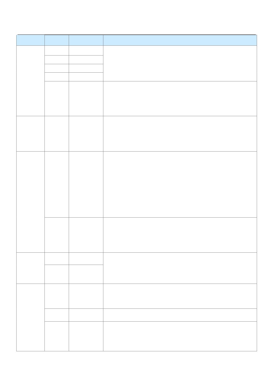
2)Description of Control Circuit Terminals
Figure 3-4 HV580L Description of control circuit terminals
Type
Terminal
Name
Function Description
Provide +10 V power supply to external unit.
Generally, it provides power supply to external potentiometer with
+10V-GNDExternal +10 V
power supply
resistance range of 1-5 k Ω.
Maximum output current: 10 mA
External
+24V
Provide +24 V power supply to external unit.
Power
power Supply
Generally, it provides power supply to DI/DO terminals and external
+24V-COMApplying to Over
supply
sensors.
voltage Category
Maximum output current: 200 mA
II circuit
Input terminal
Connect to +24 V by default.
OP
of external
When X1-X5 need to be driven by external signal, OP needs to be
power supply
connected to external power supply and be disconnected from +24 V.
Input voltage range: 0-10 VDC
VS-GND
Analog input 1
Impedance: 22 kΩ
Analog input
Input range: 0-10 V DC/4-20 mA, decided by jumper J8 on the control board
AS-GND
Analog input2
Impedance: 22 kΩ (voltage input), 500 Ω (current input)
23
Type
Terminal
Name
Function Description
X1- OP
Digital input1
Optical coupling isolation, compatible with dual polarity input
X2- OP
Digital input 2
Impedance: 2.4 kΩ
X3- OP
Digital input 3
Voltage range for level input: 9-30 V
X4- OP
Digital input 4
Digital input
High-speed
Besides features of X1-X 4, it can be used for high-speed pulse input.
X5- OP
pulse
Maximum input frequency: 100 kHz
input
Voltage or current output is decided by jumper J5.
Analog
AO1-GND
Analog output 1Output voltage range: 0-10 V
Output
Output current range: 0-20 mA
Optical coupling isolation, dual polarity open collector output
Output voltage range: 0-24 V
Digital
Output current range: 0-50 mA
Y1-CME
output 1
Note that CME and COM are internally insulated, but they are shorted
Digital
by jumper externally. In this case DO1 is driven by +24 V by default. If
output
you want to drive DO1 by external power supply, remove the jumper.
It is limited by P5-00 (Y2 terminal output mode selection).
High-speed
Y2- COM
As high-speed pulse output, the maximum frequency hits 100 kHz.
pulse output
As open-collector output, its specification is the same as that of Y1
T/A-T/B
NC terminal
Contact driving capacity:
Relay output
250 VAC, 3 A, COS ø = 0.4
T/A-T/C
NO terminal
30 VDC, 1 A
J12
Extension card
I28-pin terminal Connect to an optional card (I/O extension card, PLC
interface
card and various bus cards)
Auxiliary
J3
PG card
Support various types of PG cards: OC, differential, UVW and resolver.
interface
interface
J7
External
operation
Connect to external operation panel.
panel interface
24
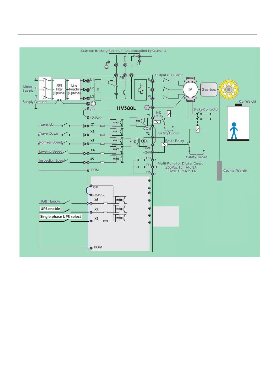
3.2.4 Wiring of AC Drive Control Circuit
Figure 3-7 AC drives control circuit connection mode
Note: All HV580L series AC drives have the same wiring mode. The figure here shows the wiring of
single-phase 220 VAC drive.
◎ indicates main circuit terminal
○ indicates control circuit terminal.
25
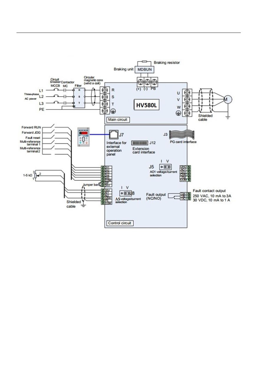
3.2.5 Electric Wiring of the HV580L
Figure 3-8 Electric wiring of the HV580L
26
Chapter 4 Operation, Display and Application
Examples
4.1 Operation Panel
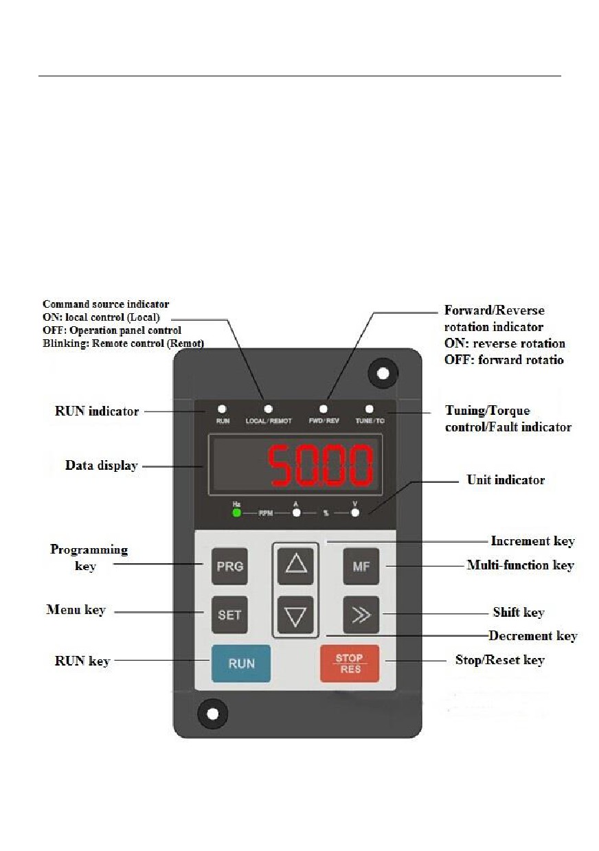
You can modify the parameters, monitor the working status and start or stop the HV580L by operating the
operation panel, as shown in the following figure:
Figure 4-1 Diagram of the operation panel
27
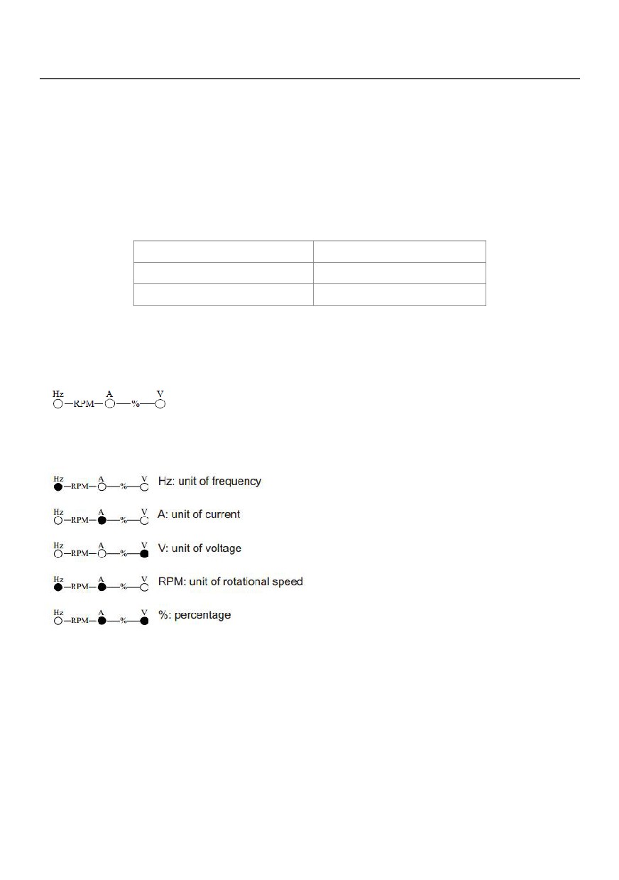
Description of Indicators:
● RUN: ON indicates that the AC drive is in the running state, and OFF indicates that the AC drive is in the
stop state.
● LOCAL/REMOT: It indicates whether the AC drive is operated by means of operation panel, terminals or
Communication.
Figure 4-1 Figure of keyboard indicator
LOCAL/REMOT: OFF
Operation panel control
LOCAL/REMOT: ON
Terminal control
LOCAL/REMOT: blinking
Communication control
FWD/REV: ON indicates reverse rotation, and OFF indicates forward rotation.
TUNE/TC: When the indicator is ON, it indicates torque control mode. When the indicator is blinking slowly, it
indicates the auto-tuning state. When the indicator is blinking quickly, it indicates the fault state.
Unit indicator lamp, used to indicate the current display data unit, there are several units: (●means that the
indicator is ON, and ○ means that the indicator is OFF.)
Digital Display:
The 5-digit LED display is able to display the set frequency, output frequency, monitoring data and fault codes.
28
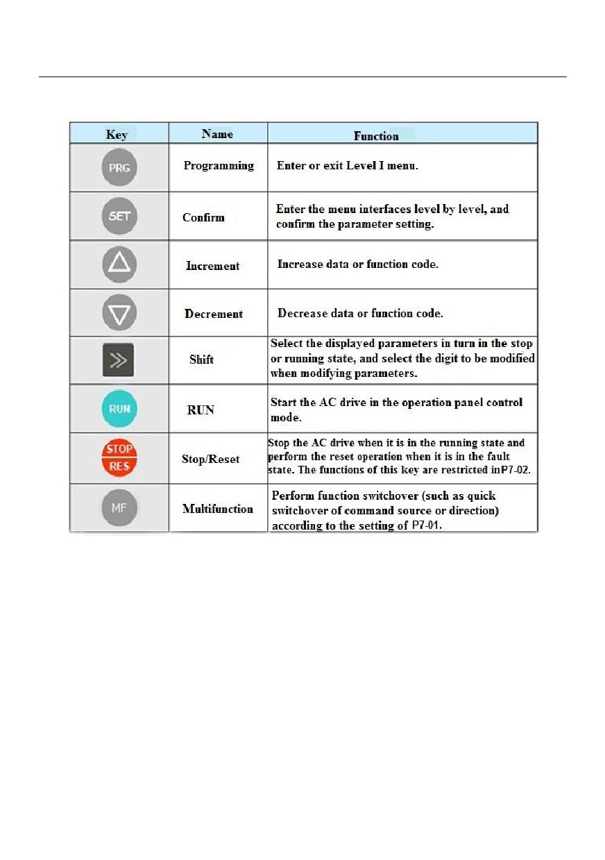
4.2 Description of keys on the operation panel
4.2 Viewing and Modifying Function Codes
The operation panel of the HV580L adopts three-level menu.
The three-level menu consists of function code group (Level I), function code (Level II), and function code
setting value (level III), as shown in the following figure.
29
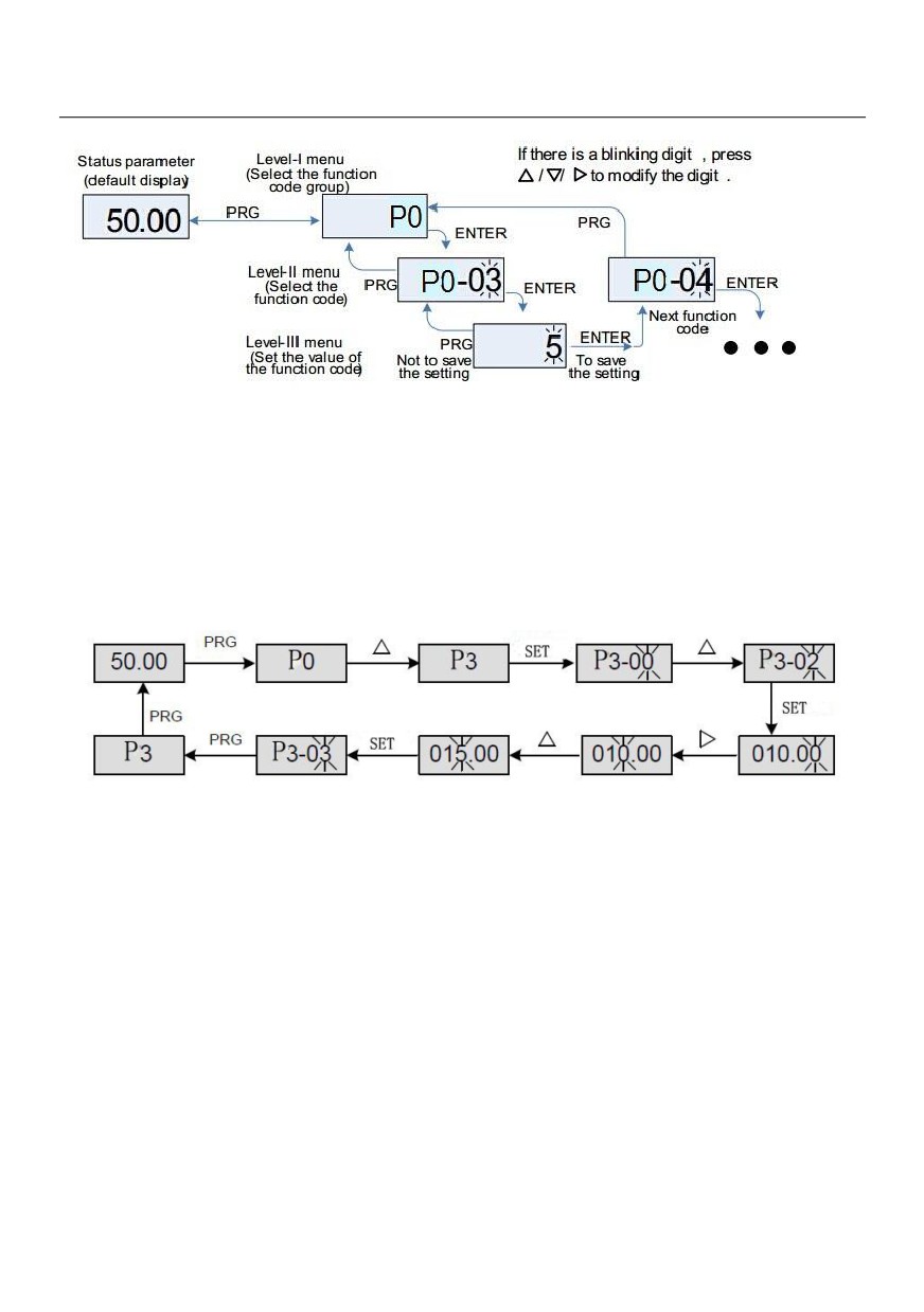
Figure 4-2 Operation procedure on the operation panel
• After you press ENTER, the system saves the parameter setting first, and then goes back to Level II menu
and shifts to the next function code.
• After you press PRG, the system does not save the parameter setting, but directly returns to Level II menu
and remains at the current function code.
Examples: Here is an example of changing the value of P3-02 to 15.00 Hz.
In Level III menu, if the parameter has no blinking digit, it means that the parameter cannot be modified. This
may be because:
• Such a function code is only readable, such as, AC drive model, actually detected parameter and running
record parameter.
• Such a function code cannot be modified in the running state and can only be changed at stop.
30
//////////////////////