HV580L Series Frequency Inverter. User Manual (Version: 3.1.14) - page 5
disabled. The holding time is not included in the acceleration time but in the running time of simple PLC.
Example 1:
P0-03 = 0
The frequency source is digital setting.
P0-08 = 2.00Hz The digital setting frequency is 2.00 Hz.
P6-03 = 5.00Hz The startup frequency is 5.00 Hz.
P6-04 = 2.0s
The startup frequency holding time is 2.0s.
In this example, the AC drive stays in the standby state and the output frequency is 0.00 Hz.
Example 2:
P0-03 = 0 The frequency source is digital setting.
P0-08 = 10.00Hz The digital setting frequency is 10.00 Hz.
P6-03 = 5.00Hz The startup frequency is 5.00 Hz.
P6-04 = 2.0s
The startup frequency holding time is 2.0s.
In this example, the AC drive accelerates to 5.00 Hz, and then accelerates to the set frequency 10.00 Hz after 2s.
Startup DC braking is generally used during restart of the AC drive after the rotating motor stops.
Pre-excitation is used to make the AC drive build magnetic field for the asynchronous motor before startup to
improve the responsiveness.
Startup DC braking is valid only for direct start (P6-00 = 0). In this case, the AC drive performs DC braking at
the set startup DC braking current. After the startup DC braking time, the AC drive starts to run. If the startup
DC braking time is 0, the AC drive starts directly without DC braking. The larger the startup DC braking current
is, the larger the braking force is.
If the startup mode is pre-excited start (P6-00 = 3), the AC drive builds magnetic field based on the set
pre-excited current. After the pre-excited time, the AC drive starts to run. If the pre-excited time is 0, the AC
drive starts directly without pre-excitation.
The startup DC braking current or pre-excited current is a percentage relative to the base value.
Acceleration/Deceleration mode
Default
0
0
Linear acceleration/deceleration
P6-07
Setting Range
1
S-curve acceleration/deceleration A
2
S-curve acceleration/deceleration B
It is used to set the frequency change mode during the AC drive start and stop process.
0: Linear acceleration/deceleration
The output frequency increases or decreases in linear mode. The HV580L provides four group of
acceleration/deceleration time, which can be selected by using P4-00 to P4-08.
• 1: S-curve acceleration/deceleration A
124
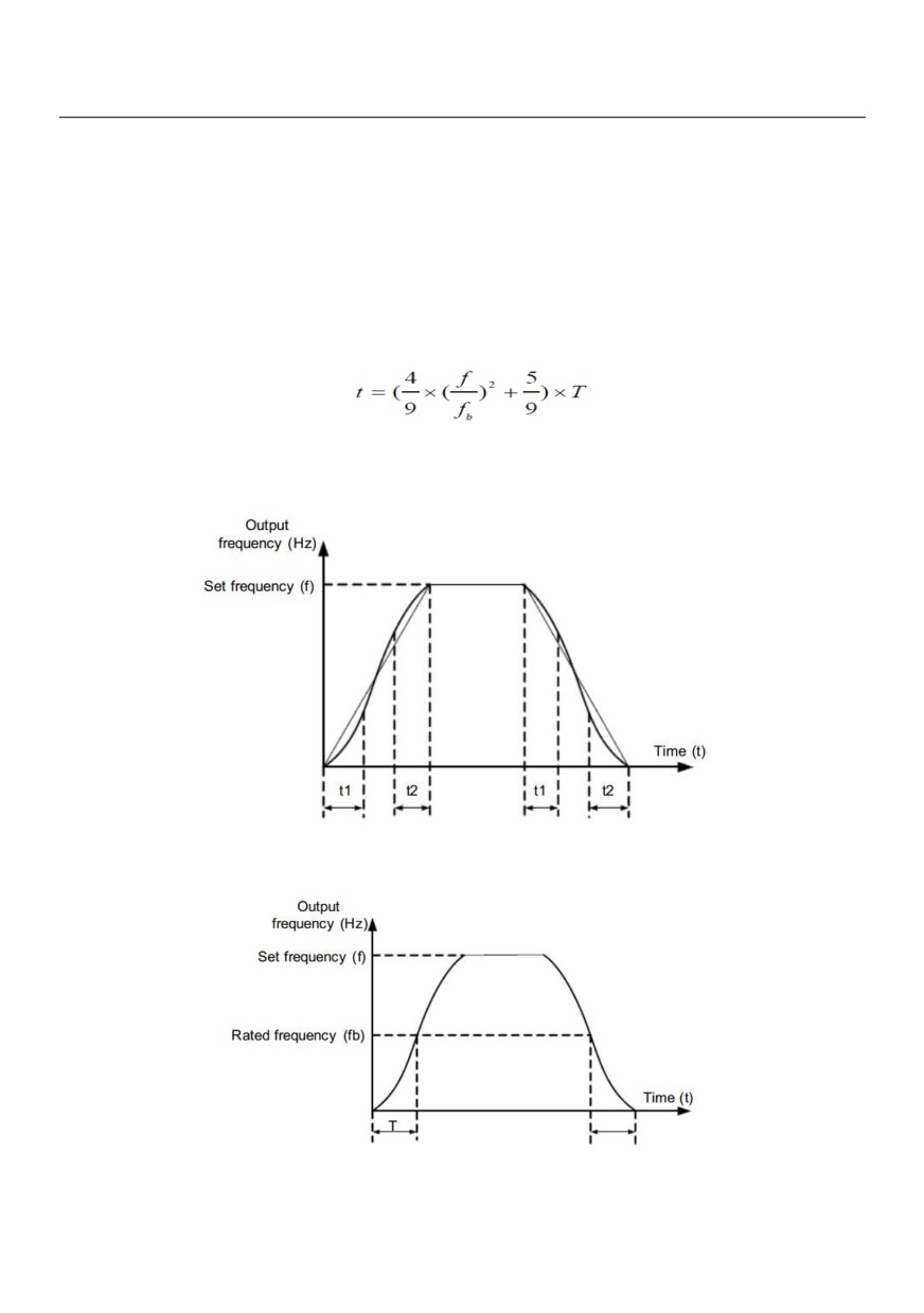
The output frequency increases or decreases along the S curve. This mode is generally used in the
applications where start and stop processes are relatively smooth, such as elevator and conveyor belt. P6-08
and P6-09 respectively define the time proportions of the start segment and the end segment.
• 2: S-curve acceleration/deceleration B
In this curve, the rated motor frequency fb is always the inflexion point. This mode is usually used in
applications where acceleration/deceleration is required at the speed higher than the rated frequency.
When the set frequency is higher than the rated frequency, the acceleration/deceleration time is:
In the formula, f is the set frequency, fb is the rated motor frequency and T is the acceleration time from 0 Hz
to fb.
Figure 6-11 S-curve acceleration/deceleration A
Figure 6-13 S-curve acceleration/deceleration B
125
Time proportion of S-curve start segment
Default
30.0%
P6-08
Setting Range
0.0% ~ (100.0%-P6-09)
Time proportion of S-curve end segment
Default
30.0%
P6-09
Setting Range
0.0% ~ (100.0%-P6-08)
These two parameters respectively define the time proportions of the start segment and the end segment of
S-curve acceleration/deceleration. They must satisfy the requirement: P6-08 + P6-09 ≤ 100.0%.
In Figure 6-11, t1 is the time defined in P6-08, within which the slope of the output frequency change
increases gradually. t2 is the time defined in P6-09, within which the slope of the output frequency change
gradually decreases to 0. Within the time between t1 and t2, the slope of the output frequency change remains
unchanged, that is, linear acceleration/deceleration.
Stop mode
Default
0
P6-10
0
Decelerate to stop
Setting Range
1
Coast to stop
0: Decelerate to stop
After the stop command is enabled, the AC drive decreases the output frequency according to the
deceleration time and stops when the frequency decreases to zero.
1: Coast to stop
After the stop command is enabled, the AC drive immediately stops the output. The motor will coast to stop
based on the mechanical inertia
Initial frequency of stop DC braking
Default
0.00Hz
P6-11
Setting Range
0.00Hz ~maximum frequency
Waiting time of stop DC braking
Default
0.0s
P6-12
Setting Range
0.0s ~ 36.0s
Stop DC braking current
Default
0%
P6-13
Setting Range
0% ~ 100%
Stop DC braking time
Default
0.0s
P6-14
Setting Range
0.0s ~ 36.0s
P6-11 (Initial frequency of stop DC braking)
During the process of decelerating to stop, the AC drive starts DC braking when the running frequency is lower
than the value set in P6-11.
P6-12 (Waiting time of stop DC braking)
When the running frequency decreases to the initial frequency of stop DC braking, the AC drive stops output
for a certain period and then starts DC braking. This prevents faults such as overcurrent caused due to DC
braking at high speed.
P6-13 (Stop DC braking current)
126
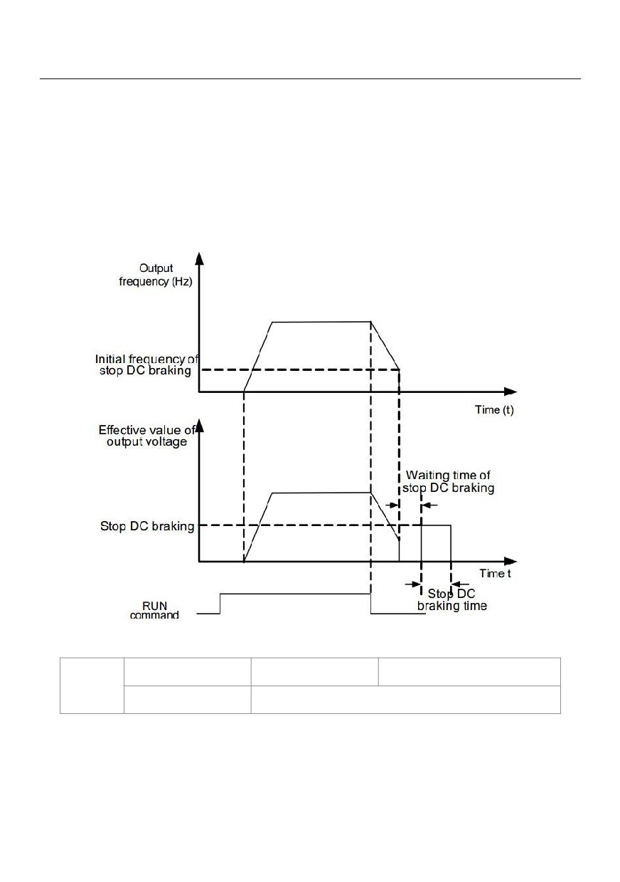
This parameter specifies the output current at DC braking and is a percentage relative to the base value.
- If the rated motor current is less than or equal to 80% of the rated AC drive current, the base value is the
rated motor current.
- If the rated motor current is greater than 80% of the rated AC drive current, the base value is 80% of the
rated AC drive current.
P6-14 (Stop DC braking time)
This parameter specifies the holding time of DC braking. If it is set to 0, DC braking is cancelled.
Figure 6-13 Stop DC braking process
Brake use ratio
Default
100%
P6-15
Setting Range
0% ~ 100%
It is valid only for the AC drive with internal braking unit and used to adjust the duty ratio of the braking unit.
The larger the value of this parameter is, the better the braking result will be. However, too larger value causes
great fluctuation of the AC drive bus voltage during the braking process.
127
Group P7 Operation Panel and Display
MF Key function selection
Default
0
0
MF key disabled
Switchover between operation panel control and
1
P7-01
remote command control (terminal or communication)
Setting Range
2
Switchover between forward rotation
3
Forward JOG
4
Reverse JOG
MF key refers to multifunctional key. You can set the function of the MF key by using this parameter. You can
perform switchover by using this key both in stop or running state.
0: MF key disabled
1: Switchover between operation panel control and remote command control (terminal or communication).
You can perform switchover from the current command source to the operation panel control (local operation).
If the current command source is operation panel control, this key is invalid.
2: Switchover between forward rotation and reverse rotation
You can change the direction of the frequency reference by using the MF key. It is valid only when the current
command source is operation panel control.
3: Forward JOG
You can perform forward JOG (FJOG) by using the MF key.
4: Reverse JOG
You can perform reverse JOG (FJOG) by using the MF key.
STOP/RESET key function
Default
1
P7-02
0
STOP/RESET key enabled only in operation panel
Setting Range
1
STOP/RESET key enabled in any operation mode
P7-03
LED display running parameters 1
Default
1F
128
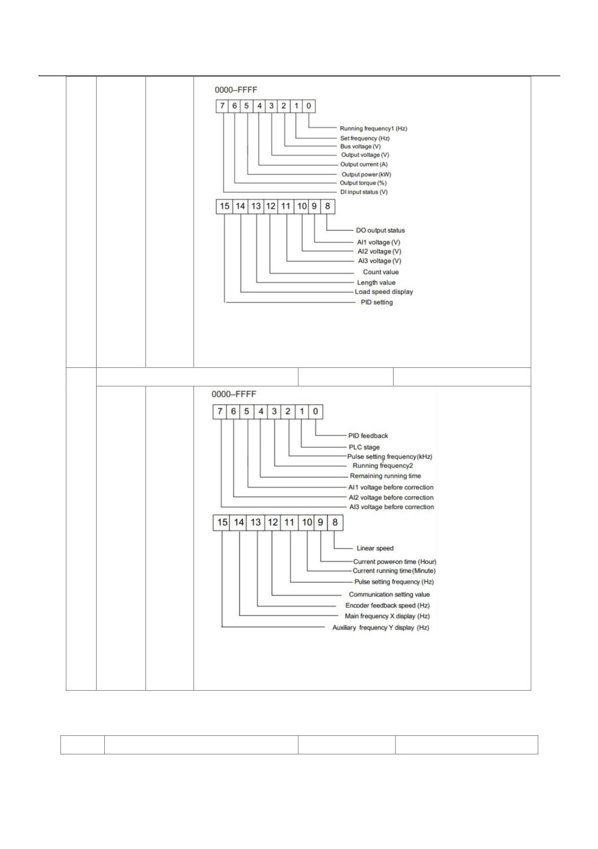
Setting
0000~
Range
FFFF
If a parameter needs to be displayed during the running, set the
corresponding bit to 1, and set P7-03 to the hexadecimal equivalent of
this binary number.
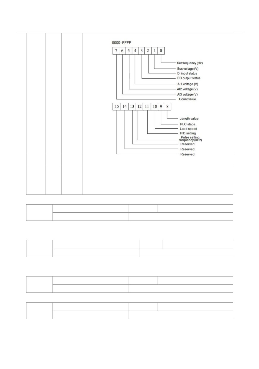
LED display running parameters 2
Default
0
P7-04
Setting
0000~
Range
FFFF
If a parameter needs to be displayed during the running, set the
corresponding bit to 1, and set P7-03 to the hexadecimal equivalent of
this binary number.
These two parameters are used to set the parameters that can be viewed when the AC drive is in the running
state. You can view a maximum of 32 running state parameters that are displayed from the lowest bit of P7-03.
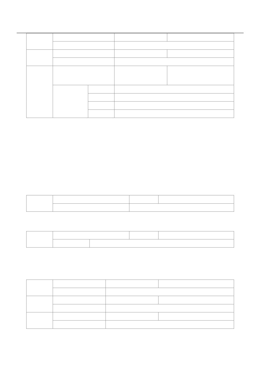
P7-05
LED display stop parameters
Default
0
129
Setting
0000~
Range
FFFF
If a parameter needs to be displayed during the running, set the
corresponding bit to 1, and set P7-05 to the hexadecimal equivalent of
this binary number.
Load speed display coefficient
Default
1.0000
P7-06
Setting Range
0.0001 ~ 6.5000
This parameter is used to adjust the relationship between the output frequency of the AC drive and the load
speed. For details, see the description of P7-12.
Heatsink temperature of inverter Module
Default
-
P7-07
Setting Range
0.0℃~ 100.0℃
It is used to display the insulated gate bipolar transistor (IGBT) temperature of the inverter module, and the
IGBT overheat protection value of the inverter module depends on the model.
Temporary software version
Default
-
P7-08
Setting Range
-
It is used to display the temporary software version of the control board.
Accumulative running time
Default
0 hour
P7-09
Setting Range
0h ~ 65535h
It is used to display the accumulative running time of the AC drive. After the accumulative running time
reaches the value set in P8-17, the terminal with the digital output function 12 becomes ON.
130
Product number
Default
P7-10
Setting Range
AC drive product number
Software version
Default
P7-11
Setting Range
Software version of control board
Number of decimal places for
Default
1
load speed
0
0 decimal place
P7-12
1
1 decimal place
Setting Range
2
2 decimal places
3
3 decimal places
P7-12 is used to set the number of decimal places for load speed display. The following gives an example to
explain how to calculate the load speed:
Assume that P7-06 (Load speed display coefficient) is 2.000 and P7-12 is 2 (2 decimal places). When the
running frequency of the AC drive is 40.00 Hz, the load speed is 40.00 x 2.000 = 80.00 (display of 2 decimal
places).
If the AC drive is in the stop state, the load speed is the speed corresponding to the set frequency, namely,
"set load speed". If the set frequency is 50.00 Hz, the load speed in the stop state is 50.00 x 2.000 = 100.00
(display of 2 decimal places).
Accumulative power-on time
Default
-
P7-13
Setting Range
0 ~ 65535 hour
It is used to display the accumulative power-on time of the AC drive since the delivery. If the time reaches the
set power-on time (P8-17), the terminal with the digital output function 24 becomes ON.
Accumulative power consumption
Default
-
P7-14
Setting Range
0 ~ 65535 kWh
It is used to display the accumulative power consumption of the AC drive until now.
Group P8 Auxiliary Functions
JOG running frequency
Default
2.00Hz
P8-00
Setting Range
0.00Hz ~maximum frequency
JOG acceleration time
Default
20.0s
P8-01
Setting Range
0.0s ~ 6500.0s
JOG deceleration time
Default
20.0s
P8-02
Setting Range
0.0s ~ 6500.0s
These parameters are used to define the set frequency and acceleration/deceleration time of the AC drive when jogging.
131
The startup mode is "Direct start" (P6-00 = 0) and the stop mode is "Decelerate to stop" (P6-10 = 0) during jogging.
Acceleration time 2
Default
Model dependent
P8-03
Setting Range
0. 0s ~ 6500.0s
Deceleration time 2
Default
Model dependent
P8-04
Setting Range
0. 0s ~ 6500.0s
Acceleration time 3
Default
Model dependent
P8-05
Setting Range
0. 0s ~ 6500.0s
Deceleration time 3
Default
Model dependent
P8-06
Setting Range
0. 0s ~ 6500.0s
Acceleration time 4
Default
Model dependent
P8-07
Setting Range
0. 0s ~ 6500.0s
Deceleration time 4
Default
Model dependent
P8-08
Setting Range
0. 0s ~ 500.0s
The HV580L provides a total of four groups of acceleration/deceleration time, that is, the preceding three groups
and the group defined by P0-17 and P0-18. Definitions of four groups are completely the same. You can switch
over between the four groups of acceleration/deceleration time through different state combinations of X
terminals. For more details, see the descriptions of P4-01 to P4-05.
Jump frequency 1
Default
0.00Hz
P8-09
Setting Range
0.00Hz ~maximum frequency
Jump frequency 2
Default
0.00Hz
P8-10
Setting Range
0.00 Hz ~maximum frequency
Frequency jump amplitude
Default
0.00Hz
P8-11
Setting Range
0.00 ~maximum frequency
If the set frequency is within the frequency jump range, the actual running frequency is the jump frequency close
to the set frequency. Setting the jump frequency helps to avoid the mechanical resonance point of the load.
The HV580L supports two jump frequencies. If both are set to 0, the frequency jump function is disabled. The
principle of the jump frequencies and jump amplitude is shown in the following figure.
132
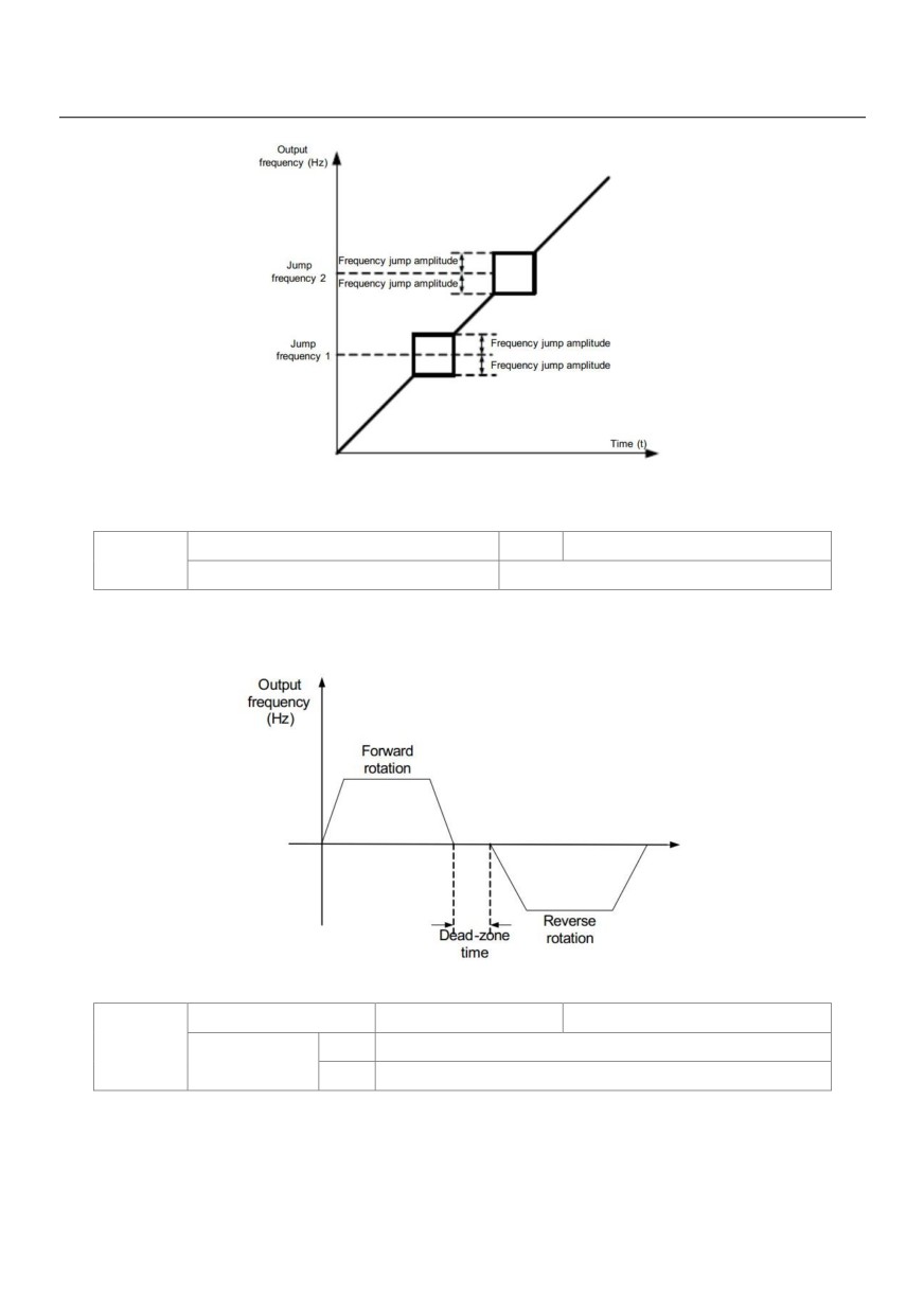
Figure 6-14 Principle of the jump frequencies and jump amplitude
Forward/Reverse rotation dead-zone time
Default
0.0s
P8-12
Setting Range
0.0s ~ 3000.0s
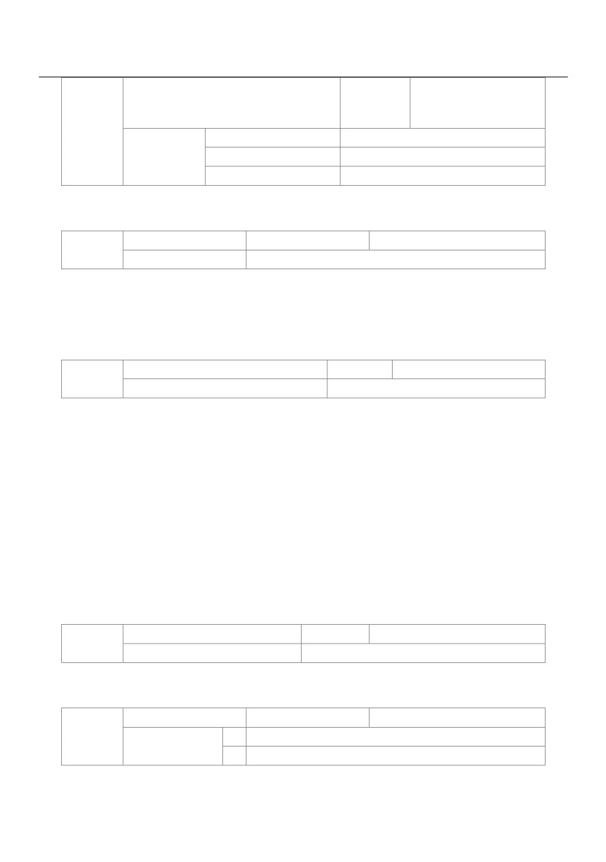
It is used to set the time when the output is 0 Hz at transition of the AC drive forward rotation and reverse
rotation, as shown in the following figure.
Figure 6-15 Forward/Reverse rotation dead-zone time
Reverse control
Default
0
P8-13
0
Enabled
Setting Range
1
Disabled
It is used to set whether the AC drive allows reverse rotation. In the applications where reverse rotation is
prohibited, set this parameter to 1.
133
Running mode when set frequency lower
Default
0
than frequency lower limit
P8-14
0
Run at frequency lower limit
Setting Range
1
Stop
2
Run at zero speed
It is used to set the AC drive running mode when the set frequency is lower than the frequency lower limit. The
HV580L provides three running modes to satisfy requirements of various applications.
Droop control
Default
0.00Hz
P8-15
Setting Range
0.00Hz ~ 10.00Hz
This function is used for balancing the workload allocation when multiple motors are used to drive the same
load. The output frequency of the AC drives decreases as the load increases. You can reduce the workload of
the motor under load by decreasing the output frequency for this motor, implementing workload balancing
between multiple motors.
Accumulative power-on time threshold
Default
0h
P8-16
Setting Range
0h ~ 65000h
If the accumulative power-on time (P7-13) reaches the value set in this parameter, the corresponding DO
terminal becomes ON.
For example, combining virtual DI/DO functions, to implement the function that the AC drive reports an alarm
when the actual accumulative power-on time reaches the threshold of 100 hours, perform the setting as
follows:
1) Set virtual X1 to user-defined fault 1: A1-00 = 44.
2) Set that the valid state of virtual X1 is from virtual DO1: A1-05 = 0000.
3) Set virtual DO1 to power-on time reached: A1-11= 24.
4) Set the accumulative power-on time threshold to 100 h: P8-16 = 100 h.
Then, the AC drive reports Err27 when the accumulative power-on time reaches 100 hours.
Accumulative running time threshold
Default
0h
P8-17
Setting Range
0h ~ 65000h
It is used to set the accumulative running time threshold of the AC drive. If the accumulative running time
(P7-09) reaches the value set in this parameter, the corresponding DO terminal becomes ON.
Startup protection
Default
0
P8-18
0
No
Setting Range
1
Yes
This parameter is used to set whether to enable the safety protection. If it is set to 1, the AC drive does not
respond to the run command valid upon AC drive power-on (for example, an input terminal is ON before
134
power-on). The AC drive responds only after the run command is cancelled and becomes valid again.
In addition, the AC drive does not respond to the run command valid upon fault reset of the AC drive. The run
protection can be disabled only after the run command is cancelled.
In this way, the motor can be protected from responding to run commands upon power-on or fault reset in
unexpected conditions.
Frequency detection value(PDT1)
Default
50.00Hz
P8-19
Setting Range
0.00Hz ~maximum frequency
Frequency detection hysteresis (FDT hysteresis 1)
Default
5.0%
P8-20
Setting Range
0.0% ~ 100.0% (FDT1 level)
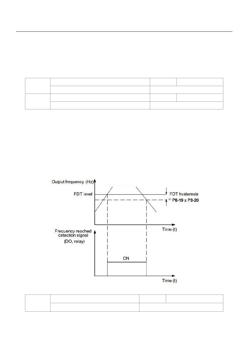
If the running frequency is higher than the value of P8-19, the corresponding DO terminal becomes ON. If the
running frequency is lower than value of P8-19, the DO terminal goes OFF
These two parameters are respectively used to set the detection value of output frequency and hysteresis
value upon cancellation of the output. The value of P8-20 is a percentage of the hysteresis frequency to the
frequency detection value (P8-19).
Figure 6-16 FDT level
Detection range of frequency reached
Default
0.0%
P8-21
Setting Range
0.00 ~ 100%( maximum frequency )
If the AC drive running frequency is within the certain range of the set frequency, the corresponding DO
terminal becomes ON.
135
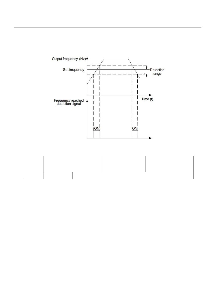
This parameter is used to set the range within which the output frequency is detected to reach the set
frequency. The value of this parameter is a percentage relative to the maximum frequency. The detection
range of frequency reached is shown in the following figure.
Figure 6-17 Detection range of frequency reached
Jump frequency during
Default
0
P8-22
acceleration/deceleration
Setting Range
0: Disabled;
1: Enabled
It is used to set whether the jump frequencies are valid during acceleration/deceleration.
When the jump frequencies are valid during acceleration/deceleration, and the running frequency is within the
frequency jump range, the actual running frequency will jump over the set frequency jump amplitude (rise
directly from the lowest jump frequency to the highest jump frequency). The following figure shows the
diagram when the jump frequencies are valid during acceleration/deceleration.
136
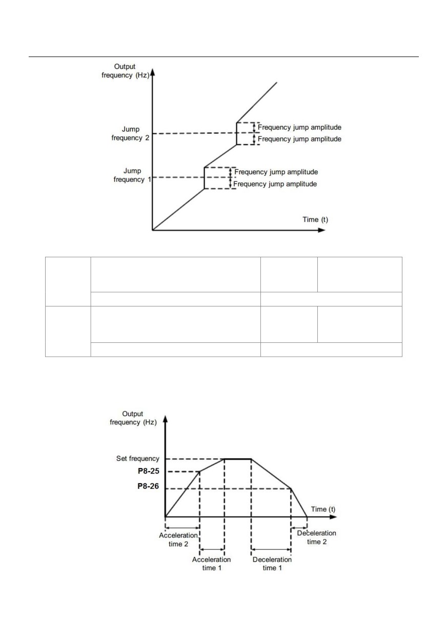
Figure 6-18 Diagram when the jump frequencies are valid during acceleration/deceleration
Frequency switchover point between
Default
0.00Hz
P8-25
acceleration time 1 and acceleration time 2
Setting Range
0.00Hz ~maximum frequency
Frequency switchover point between
Default
0.00Hz
P8-26
deceleration time 1 and deceleration time 2
Setting Range
0.00Hz ~maximum frequency
This function is valid when motor 1 is selected and acceleration/deceleration time switchover is not performed
by means of X terminal. It is used to select different groups of acceleration/deceleration time based on the
running frequency range rather than DI terminal during the running process of the AC drive.
Figure 6-19 Acceleration/deceleration time switchovers
137
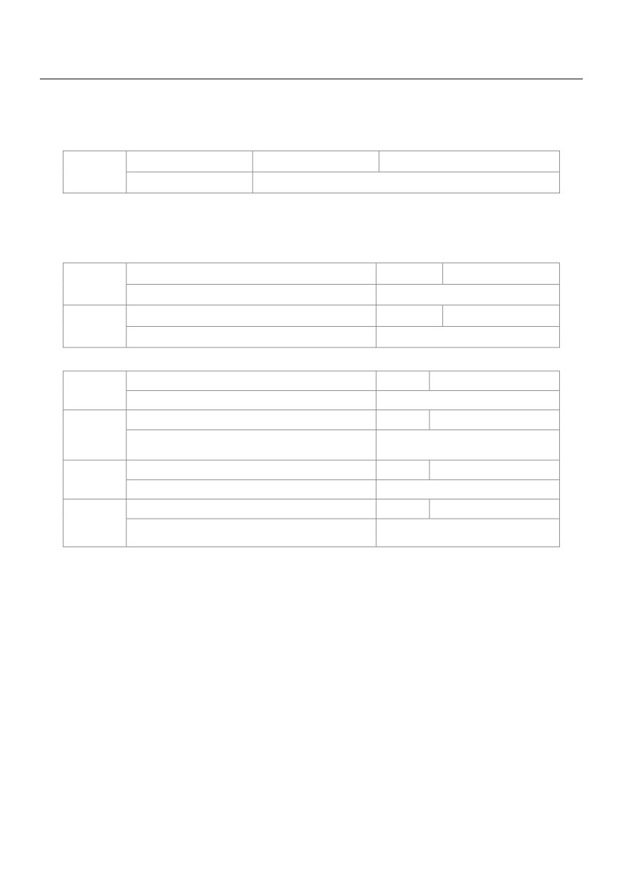
During acceleration, if the running frequency is smaller than the value of P8-25, acceleration time 2 is selected.
If the running frequency is larger than the value of P8-25, acceleration time 1 is selected.
During deceleration, if the running frequency is larger than the value of P8-26, deceleration time 1 is selected.
If the running frequency is smaller than the value of P8-26, deceleration time 2 is selected.
Terminal JOG preferred
Default
0
P8-27
Setting Range
0: Disabled;
1: Enabled
It is used to set whether terminal JOG is preferred.
If terminal JOG is preferred, the AC drive switches to terminal JOG running state when there is a terminal JOG
command during the running process of the AC drive.
Frequency detection value (PDT2)
Default
50.00Hz
P8-28
Setting Range
0.00Hz ~ maximum frequency
Frequency detection hysteresis (FDT hysteresis 2)
Default
5.0%
P8-29
Setting Range
0.0% ~ 100.0 % ( PDT2 level)
The frequency detection function is the same as FDT1 function. For details, refer to the descriptions of P8-19 and P8-20.
Any frequency reaching detection value 1
Default
50.00Hz
P8-30
Setting Range
0.00Hz ~ maximum frequency
Any frequency reaching detection amplitude 1
Default
0.0%
P8-31
0.0% ~ 100.0%(maximum
Setting Range
frequency)
Any frequency reaching detection value 2
Default
50.00Hz
P8-32
Setting Range
0.00Hz ~maximum frequency
Any frequency reaching detection amplitude 2
Default
0.0%
P8-33
0.0% ~ 100.0%(maximum
Setting Range
Frequency)
If the output frequency of the AC drive is within the positive and negative amplitudes of the any frequency
reaching detection value, the corresponding DO becomes ON.
The HV580L provides two groups of any frequency reaching detection parameters, including frequency
detection value and detection amplitude, as shown in the following figure.
138
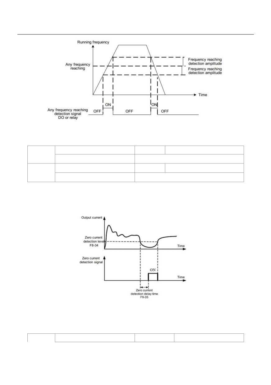
Figure 6-20 Any frequency reaching detection
Zero current detection level
Default
5.0%
P8-34
Setting Range
0.0% ~ 300.0%( rated motor current)
Zero current detection delay time
Default
0.10s
P8-35
Setting Range
0.00s ~ 600.00s
If the output current of the AC drive is equal to or less than the zero current detection level and the duration
exceeds the zero current detection delay time, the corresponding DO becomes ON. The zero current
detection is shown in the following figure.
Figure 6-21 Zero current detection
P8-36
Output overcurrent threshold
Default
200.0%
139
0.0%( no detection );0.1% ~ 300.0%(rated motor
Setting Range
current)
Output overcurrent detection
Default
0.00s
P8-37
delay time
Setting Range
0.00s ~ 600.00s
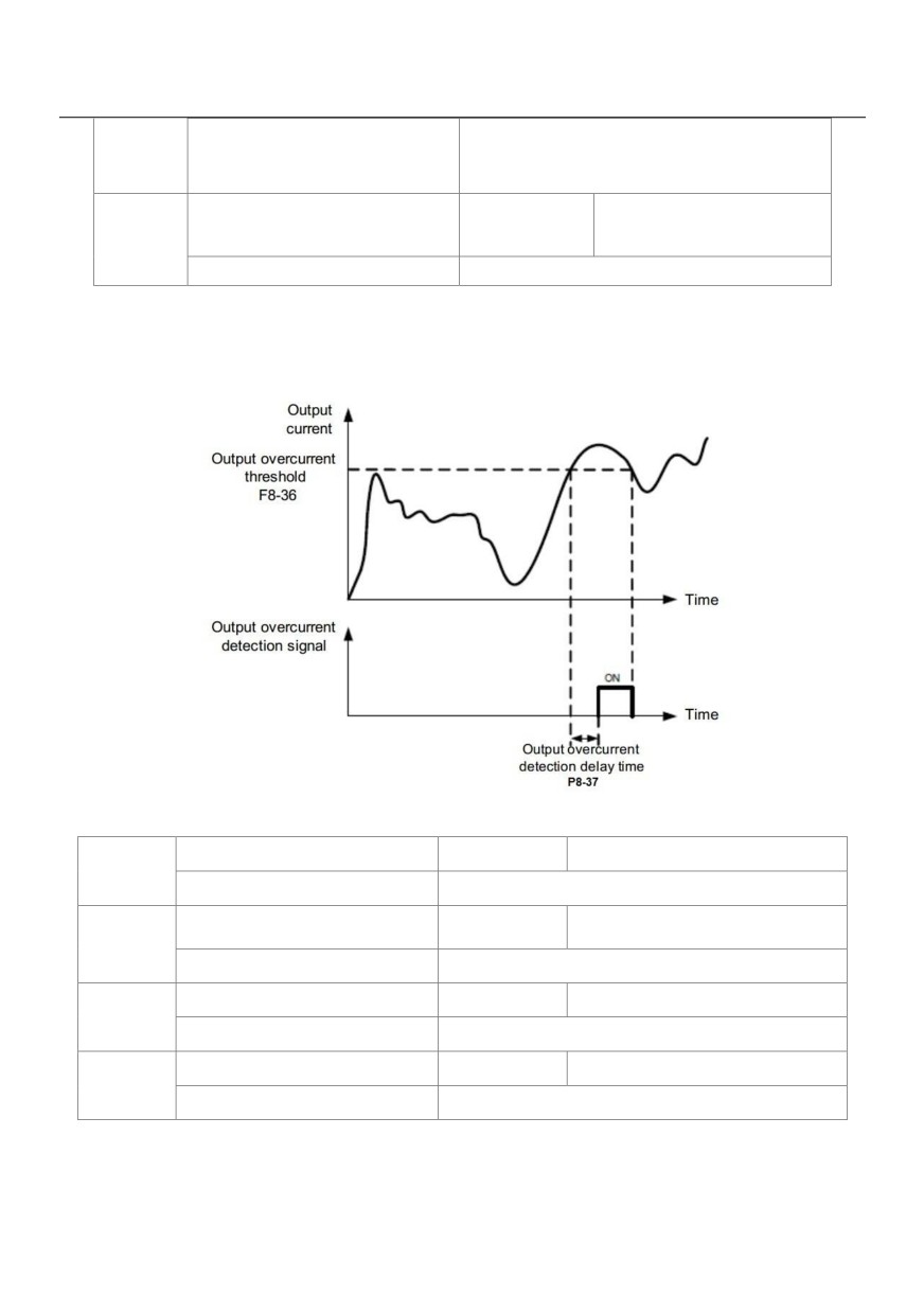
If the output current of the AC drive is equal to or higher than the overcurrent threshold and the duration
exceeds the detection delay time, the corresponding DO becomes ON. The output overcurrent detection
function is shown in the following figure.
Figure 6-22 Output overcurrent detection
Any current reaching 1
Default
100.0%
P8-38
Setting Range
0.0% ~ 300.0%( rated motor current )
Any current reaching 1 amplitude
Default
0.0%
P8-39
Setting Range
0.0% ~ 300.0%( rated motor current )
Any current reaching 2
Default
100.0%
P8-40
Setting Range
0.0% ~ 300.0%( rated motor current )
Any current reaching 2 amplitude
Default
0.0%
P8-41
Setting Range
0.0% ~ 300.0%( rated motor current )
If the output current of the AC drive is within the positive and negative amplitudes of any current reaching
detection value, the corresponding DO becomes ON.
140
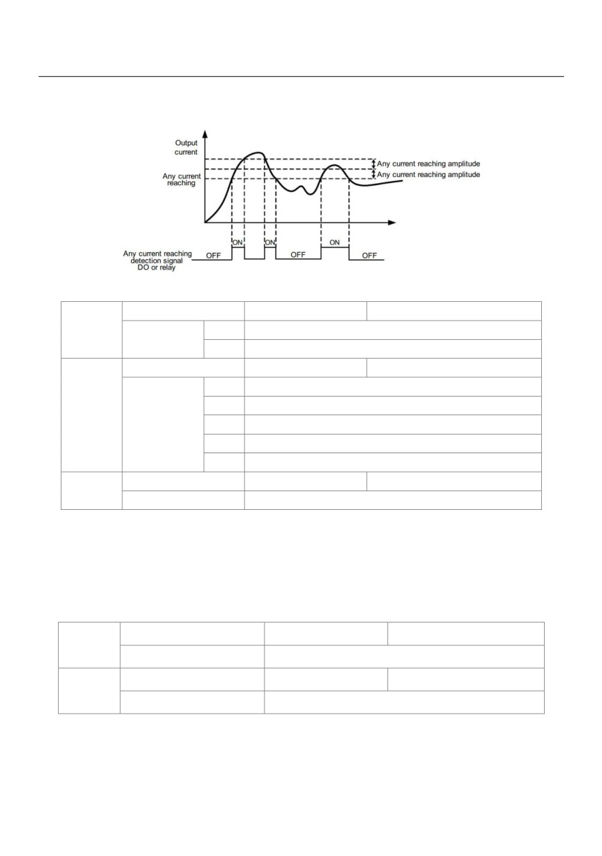
The HV580L provides two groups of any current reaching detection parameters, including current detection
value and detection amplitudes, as shown in the following figure.
Figure 6-23 Any current reaching detection
Timing function
Default
0
P8-42
0
Disabled
Setting Range
1
Enabled
Timing duration source
Default
0
0
P8-44
1
VS
P8-43
Setting Range
2
AS
3
VS2
(100% of analog input corresponds to the value of P8-44)
Timing duration
Default
0.0Min
P8-44
Setting Range
0.0Min ~ 6500.0Min
These parameters are used to implement the AC drive timing function.
If P8-42 is set to 1, the AC drive starts to time at startup. When the set timing duration is reached, the AC drive
stops automatically and meanwhile the corresponding DO becomes ON.
The AC drive starts timing from 0 each time it starts up and the remaining timing duration can be queried by U0-20.
The timing duration is set in P8-43 and P8-44, in unit of minute.
VS input voltage lower limit
Default
3.10V
P8-45
Setting Range
0.00V ~ P8-46
VS input voltage upper limit
Default
6.80V
P8-46
Setting Range
P8-45 ~ 10.00V
These two parameters are used to set the limits of the input voltage to provide protection on the AC drive.
When the VS input is larger than the value of P8-46 or smaller than the value of P8-45, the corresponding DO
becomes ON, indicating that VS input exceeds the limit.
141
Module temperature threshold
Default
75℃
P8-47
Setting Range
0.00V ~ P8-46
When the heatsink temperature of the AC drive reaches the value of this parameter, the corresponding DO
becomes ON, indicating that the module temperature reaches the threshold.
Cooling fan control
Default
0
P8-48
Setting Range
0:Fan working during running; 1: Fan working continuously
It is used to set the working mode of the cooling fan. If this parameter is set to 0, the fan works when the AC
drive is in running state. When the AC drive stops, the cooling fan works if the heatsink temperature is higher
than 40°C, and stops working if the heatsink temperature is lower than 40°C.
If this parameter is set to 1, the cooling fan keeps working after power-on.
Wakeup frequency
Default
0.00Hz
P8-49
Setting Range
Dormant frequency (P8-51) to maximum frequency (P0-10)
Wakeup delay time
Default
0.0s
P8-50
Setting Range
0.0s ~ 6500.0s
Dormant frequency
Default
0.00Hz
P8-51
Setting Range
0.00Hz ~wakeup frequency (P8-49)
Dormant delay time
Default
0.0s
P8-52
Setting Range
0.0s ~ 6500.0s
These parameters are used to implement the dormant and wakeup functions in the water supply application.
When the AC drive is in running state, the AC drive enters the dormant state and stops automatically after the
dormant delay time (P8-52) if the set frequency is lower than or equal to the dormant frequency (P8-51).
When the AC drive is in dormant state and the current running command is effective, the AC drives starts up
after the wakeup delay time (P8-50) if the set frequency is higher than or equal to the wakeup frequency
(P8-49).
Generally, set the wakeup frequency equal to or higher than the dormant frequency. If the wakeup frequency
and dormant frequency are set to 0, the dormant and wakeup functions are disabled.
When the dormant function is enabled, if the frequency source is PID, whether PID operation is performed in
the dormant state is determined by PA-28. In this case, select PID operation enabled in the stop state (PA-28
= 1).
Current running time reached
Default
0.0Min
P8-53
Setting Range
0.0Min ~ 6500.0Min
142
If the current running time reaches the value set in this parameter, the corresponding DO becomes ON,
indicating that the current running time is reached.
Output power correction coefficient
Default
100.0%
P8-54
Setting Range
0.00% ~ 200.0%
Brake release current threshold
Default
100.0%
P8-55
Setting Range
0.00% ~ 200.0%
Brake release frequency threshold
Default
0Hz
P8-56
Setting Range
0.00 to 25.00Hz
Brake release delay ON set time
Default
0.1s
P8-57
Setting Range
0.0 to 5.0s
If the drive output frequency is exceed the frequency threshold defined by P8.56, and output current is
exceed the current threshold defined by P8.55, delay the time defined by P8.57, the brake is released.
Brake apply frequency threshold
Default
0.50Hz
P8-58
Setting Range
0.00 to 25.00Hz
Brake apply delay OFF set time
Default
0.2s
P8-59
Setting Range
0.0 to 5.0s
When the drive is stopping, if the output frequency is below the frequency threshold defined by P8.58, delay
the time defined by P8.59, the brake is applied.
Drive run delay ON set time
Default
0.2s
P8-60
Setting Range
0.00 to 10.00s
This parameter define the delay time between the run command and the drive actually output.
MC contactor delay OFF set time
Default
0.2s
P8-61
Setting Range
0.00 to 10.00s
The MC contactor de-energies after the desired set time have elapse. This parameter defines the
delay time.
Current threshold in UPS mode
Default
100%
P8-62
Setting Range
0 to 200
143
Acceleration time in UPS mode
Default
3.0s
P8-63
Setting Range
0.0 to 20.0
Deceleration time in UPS mode
Default
3.0s
P8-64
Setting Range
0.0 to 20.0
Brake apply keep frequency set time
Default
0.5s
P8-65
Setting Range
0.00 to 10.00
Time proportion of S-curve at stop
Default
20.0%
P8-66
stage start
Setting Range
0.00% to Min[(100%-P8.67),80%]
Time proportion of S-curve at stop
Default
30.0%
P8-67
stage end
Setting Range
0.00% to Min[(100%-P8.66),80%]
UPS input phase mode select
Default
0
P8-68
0: Three phase UPS
Setting Range
1: Single/Two phase UPS
Single/Two phase UPS under voltage
Default
60.0 (210V)
P8-69
point
Setting Range
60.0 to 140.0
Group P9 Fault and Protection
Motor overload protection selection
Default
1
P9-00
0
Disabled
Setting Range
1
Enabled
Motor overload protection gain
Default
1
P9-01
Setting Range
0.10 ~ 10.00
P9-00 = 0
The motor overload protective function is disabled. The motor is exposed to potential damage due to
overheating. A thermal relay is suggested to be installed between the AC drive and the motor.
144
P9-00 = 1
The AC drive judges whether the motor is overloaded according to the inverse time-lag curve of the motor
overload protection.
The inverse time-lag curve of the motor overload protection is:
220% x P9-01 x rated motor current (if the load remains at this value for one minute, the AC drive reports
motor overload fault), or 150% x P9-01 x rated motor current (if the load remains at this value for 60 minutes,
the AC drive reports motor overload fault)
Set P9-01 properly based on the actual overload capacity. If the value of P9-01 is set too large, damage to the
motor may result because the motor overheats but the AC drive does not report the alarm.
Motor overload warning coefficient
Default
80%
P9-02
Setting Range
50% ~ 100%
This function is used to give a warning signal to the control system via DO before motor overload rotection.
This parameter is used to determine the percentage, at which pre-warning is performed before motor overload.
The larger the value is, the less advanced the pre-warning will be.
When the accumulative output current of the AC drive is greater than the value of the overload inverse
time-lag curve multiplied by P9-02, the DO terminal on the AC drive allocated with function 6 (Motor overload
pre-warning) becomes ON.
Overvoltage stall gain
Default
0
P9-03
Setting Range
0 (no stall overvoltage)~ 100
Overvoltage stall protective voltage
Default
130%
P9-04
Setting Range
120% ~ 150%
When the DC bus voltage exceeds the value of P9-04 (Overvoltage stall protective voltage) during
deceleration of the AC drive, the AC drive stops deceleration and keeps the present running frequency. After
the bus voltage declines, the AC drive continues to decelerate.
P9-03 (Overvoltage stall gain) is used to adjust the overvoltage suppression capacity of the AC drive. The
larger the value is, the greater the overvoltage suppression capacity will be.
In the prerequisite of no overvoltage occurrence, set P9-03 to a small value. For small-inertia load, the value
should be small. Otherwise, the system dynamic response will be slow. For large-inertia load, the value should
be large. Otherwise, the suppression result will be poor and an overvoltage fault may occur.
If the overvoltage stall gain is set to 0, the overvoltage stall function is disabled.
145
Overcurrent stall gain
Default
20
P9-05
Setting Range
0 ~ 100
Overcurrent stall protective current
Default
150%
P9-06
Setting Range
100% ~ 200%
When the output current exceeds the overcurrent stall protective current during acceleration/deceleration of
the AC drive, the AC drive stops acceleration/deceleration and keeps the present running frequency. After the
output current declines, the AC drive continues to accelerate/decelerate.
P9-05 (Overcurrent stall gain) is used to adjust the overcurrent suppression capacity of the AC drive. The
larger the value is, the greater the overcurrent suppression capacity will be. In the prerequisite of no
overcurrent occurrence, set P9-05 to a small value.
For small-inertia load, the value should be small. Otherwise, the system dynamic response will be slow. For
large-inertia load, the value should be large. Otherwise, the suppression result will be poor and overcurrent
fault may occur.
If the overcurrent stall gain is set to 0, the overcurrent stall function is disabled.
Short-circuit to ground upon power-on
Default
1
P9-07
Setting Range
0: Disabled; 1: Enabled
It is used to determine whether to check the motor is short-circuited to ground at power-on of the AC drive. If
this function is enabled, the AC drive's UVW will have voltage output a while after power-on.
Fault auto reset times
Default
0
P9-09
Setting Range
0 ~ 20
It is used to set the times of fault auto resets if this function is used. After the value is exceeded, the AC drive
will remain in the fault state.
DO action during fault auto reset
Default
0
P9-10
Setting Range
0: Not act; 1: Act
It is used to decide whether the DO acts during the fault auto reset if the fault auto reset function is selected.
Time interval of fault auto reset
Default
1.0s
P9-11
Setting Range
0.1s ~ 100.0s
It is used to set the waiting time from the alarm of the AC drive to fault auto reset.
Input phase loss
P9-12
protection/contactor energizing
Default
11
protection selection
146
Unit's digit: Input phase loss protection
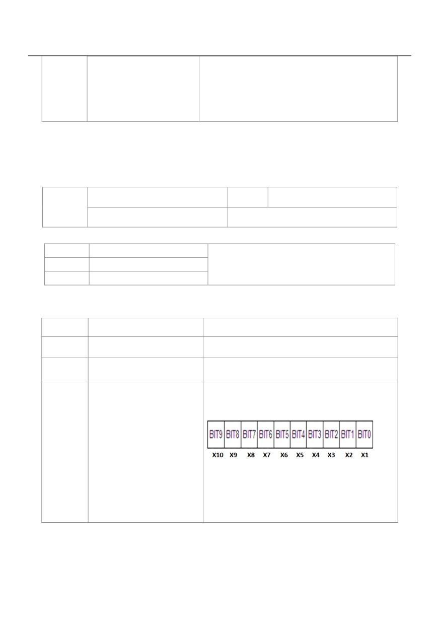
Ten's digit: Contactor energizing
Setting Range
0: Disabled
1: Enabled
It is used to determine whether to perform input phase loss or contactor energizing protection.
For every voltage class, the HV580L AC drives of powers equal to or greater than those listed in the preceding
table provide the function of input phase loss or contactor energizing protection. The HV580L AC drives below
the power listed in the table do not have the function no matter whether P9-12 is set to 0 or 1.
Output phase loss protection selection
Default
1
P9-13
Setting Range
0: Disabled
1: Enabled
It is used to determine whether to perform output phase loss protection.
P9-14
1st fault type
P9-15
2nd fault type
0 ~ 99
P9-16
3rd (latest) fault type
It is used to record the types of the most recent three faults of the AC drive. 0 indicates no fault. For possible
causes and solution of each fault, refer to Chapter 8.
P9-17
Frequency upon 3rd fault
It displays the frequency when the latest fault occurs.
P9-18
Current upon 3rd fault
It displays the current when the latest fault occurs.
It displays the bus voltage when the latest fault Occurs.
P9-19
Bus voltage upon 3rd fault
It displays the status of all DI terminals when the latest
fault occurs. The sequence is as follows:
P9-20
Digital Input status upon 3rd fault
If the X terminal is ON, the setting is 1. If the X terminal
is OFF, the setting is 0. The value is the equivalent
decimal number converted from the X terminal status.
147
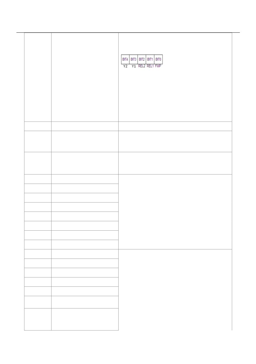
It displays the status of all output terminals when the
latest fault occurs. The sequence is as follows:
Output terminal status
P9-21
If an output terminal is ON, the setting is 1. If the output
upon 3rd fault
terminal is OFF, the setting is 0. The value is the
equivalent decimal number converted from the X
terminal statuses.
P9-22
AC drive status upon 3rd
Reserved
Power-on time upon 3rd
It displays the present power-on time when the latest
P9-23
Fault
fault occurs.
It displays the present running time when the latest fault
Running time upon 3rd
P9-24
Fault
occurs.
P9-27
Frequency upon 2nd fault
P9-28
Current upon 2nd fault
P9-29
Bus voltage upon 2nd fault
P9-30
X terminal status upon 2nd fault
Same as P9-17 ~ P9-24
P9-31
Output terminal status
P9-32
Frequency upon 2nd fault
P9-33
Current upon 2nd fault
P9-34
Bus voltage upon 2nd fault
P9-37
X terminal status upon 1st fault
P9-38
Current upon 1st fault
P9-39
Bus voltage upon 3rd fault
P9-40
X terminal status upon 1st fault
Same as P9-17 ~ P9-24
P9-41
Output terminal status
P9-42
AC Drive status upon 1st fault
Output terminal status upon 1st
P9-43
fault
148
P9-44
Frequency upon 1st fault
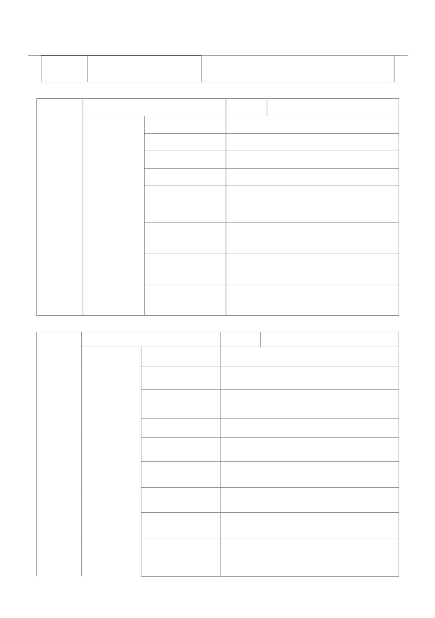
Fault protection action selection 1
Default
00000
Unit's digit
Motor overload (Err11)
0
Coast to stop
1
Stop according to the stop mode
2
Continue to run
Power input phase loss (Err12)
Ten's digit
P9-47
(Same as unit's digit)
Setting Range
Power output phase loss (Err13)
Hundred's digit
(Same as unit's digit)
External equipment fault (Err15)
Thousand's digit
(Same as unit's digit)
Communication fault (Err16)
Ten thousand's digit
(Same as unit's digit)
Fault protection action selection 2
Default
00000
Unit's digit
Encoder fault (Err20)
0
Coast to stop
Switch over to V/F control, stop according to the
1
stop mode
2
Switch over to V/F control, continue to run
Ten's digit
EEPROM read-write fault (Err21)
P9-48
Setting Range
0
Coast to stop
1
Stop according to the stop mode
Hundred's digit
Reserved
Motor overheat (Err25)
Thousand's digit
Same as unit's digit in P9-47
149
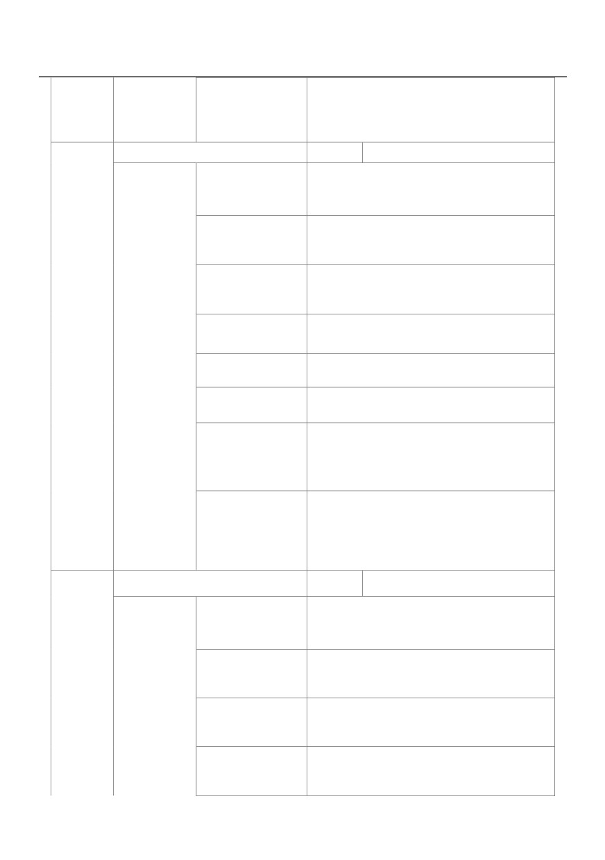
Accumulative running time reached (Err26) Same
Ten thousand's digit
as unit's digit in P9-47
Fault protection action selection 3
Default
00000
User-defined fault 1(Err27)
Unit's digit
Same as unit's digit in P9-47
User-defined fault 2(Err28)
Ten's digit
Same as unit's digit in P9-47
Accumulative power-on time reached (Err29) Same
Hundred's digit
as unit's digit in P9-47
Thousand's digit
Load becoming 0 (Err30)
P9-49
Setting Range
0
Coast to stop
1
Stop according to the stop mode
Continue to run at 7% of rated motor frequency
2
and resume to the set frequency if the load
Recovers
PID feedback lost during running (Err31) Same as
Ten thousand's digit
unit's digit in P9-47
Fault protection action selection 4
Default
00000
Too large speed deviation, (Err42)
Unit's digit
Same as unit's digit in P9-47
Motor over-speed (Err43)
Ten's digit
P9-50
Same as unit's digit in P9-47
Setting Range
Initial position fault (Err51)
Hundred's digit
Same as unit's digit in P9-47
Speed feedback fault (Err52)
Thousand's digit
Same as unit's digit in P9-47
150

Ten thousand's digit
Reserved
If "Coast to stop" is selected, the AC drive displays Err** and directly stops.
• If "Stop according to the stop mode" is selected, the AC drive displays A** and stops according to the stop
mode. After stop, the AC drive displays Err**.
• If "Continue to run" is selected, the AC drive continues to run and displays A**. The running frequency is set
in P9-54.
Frequency selection for
Default
0
continuing to run upon fault
0
Current running frequency
P9-54
1
Set frequency
Setting Range
2
Frequency upper limit
3
Frequency lower limit
4
Backup frequency upon abnormality
Backup frequency upon
Default
100.0%
abnormality
P9-55
0.0% ~ 100.0%(maximum frequency)
Setting Range
If a fault occurs during the running of the AC drive and the handling of fault is set to "Continue to run", the AC
drive displays A** and continues to run at the frequency set in P9-54.
The setting of F9-55 is a percentage relative to the maximum frequency.
Type of motor temperature sensor
Default
0
P9-56
0
No temperature sensor
Setting Range
1
PT100
2
PT1000
Motor overheat protection threshold
Default
110℃
P9-57
Setting Range
0℃~ 200℃
Motor overheat warning threshold
Default
90℃
P9-58
Setting Range
0℃~ 200℃
The signal of the motor temperature sensor needs to be connected to the optional I/O extension card. VS2 on
151
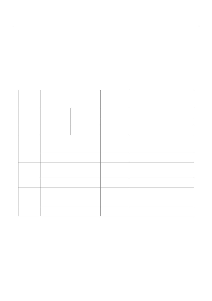
the extension card can be used for the temperature signal input.
The motor temperature sensor is connected to VS2 and PGND of the extension card. The VS2 terminal of the
HV580L supports both PT100 and PT1000. Set the sensor type correctly during the use. You can view the
motor temperature via C-34.
If the motor temperature exceeds the value set in P9-57, the AC drive reports an alarm and acts according to
the selected fault protection action.
If the motor temperature exceeds the value set in P9-58, the DO terminal on the AC drive allocated with
function 39 (Motor overheat warning) becomes ON.
Action selection at instantaneous
Default
0
power failure
P9-59
0
Invalid
Setting Range
1
Decelerate
2
Decelerate to stop
Action pause judging voltage at
Default
90.0%
P9-60
instantaneous power failure
Setting Range
80.0% ~ 100.0%
Voltage rally judging time at
Default
0.50s
P9-61
instantaneous power failure
Setting Range
0.00s ~ 100.00s
Action judging voltage at
Default
80.0%
P9-62
instantaneous power failure
Setting Range
60.0% ~ 100.0%( standard bus voltage )
Upon instantaneous power failure or sudden voltage dip, the DC bus voltage of the AC drive reduces. This
function enables the AC drive to compensate the DC bus voltage reduction with the load feedback energy by
reducing the output frequency so as to keep the AC drive running continuously.
• If P9-59 = 1, upon instantaneous power failure or sudden voltage dip, the AC drive decelerates. Once the
bus voltage resumes to normal, the AC drive accelerates to the set frequency. If the bus voltage remains
normal for the time exceeding the value set in P9-61, it is considered that the bus voltage resumes to normal.
152
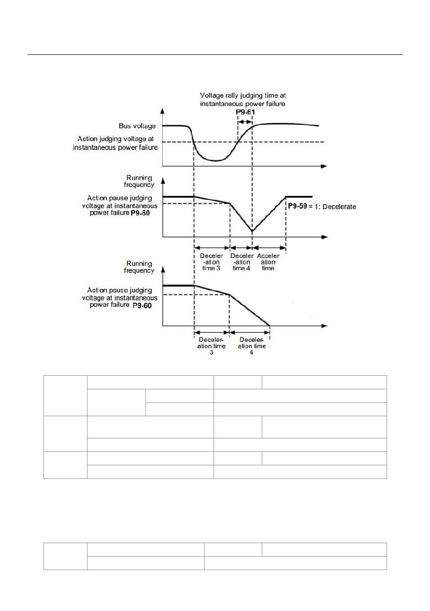
• If P9-59 = 2, upon instantaneous power failure or sudden voltage dip, the AC drive decelerates to stop.
Figure 6-24 AC drive action diagram upon instantaneous power failure
Protection upon load becoming 0
Default
0
P9-63
0
Disabled
Setting Range
1
Enabled
Detection level of load becoming 0
Default
10.0%
P9-64
Setting Range
0.0% ~ 100.0% (rated motor current)
Detection time of load becoming 0
Default
1.0s
P9-65
Setting Range
0.0s ~ 60.0s
If protection upon load becoming 0 is enabled, when the output current of the AC drive is lower than the
detection level (P9-64) and the lasting time exceeds the detection time (P9-65), the output frequency of the
AC drive automatically declines to 7% of the rated frequency. During the protection, the AC drive automatically
accelerates to the set frequency if the load resumes to normal.
Over-speed detection value
Default
20.0%
P9-67
Setting Range
0.0% ~ 50.0%( maximum frequency)
153
Over-speed detection time
Default
1.0s
P9-68
Setting Range
0.0s ~ 60.0s
This function is valid only when the AC drive runs in the CLVC mode. If the actual motor rotational speed
detected by the AC drive exceeds the maximum frequency and the excessive value is greater than the value
of P9-67 and the lasting time exceeds the value of P9-68, the AC drive reports Err43 and acts according to the
selected fault protection action.
If the over-speed detection time is 0.0s, the over-speed detection function is disabled.
Detection value of too large
Default
20.0%
P9-69
speed deviation
Setting Range
0.0% ~ 50.0%(maximum frequency)
Detection time of too large speed
Default
5.0s
P9-70
deviation
Setting Range
0.0s ~ 60.0s
This function is valid only when the AC drive runs in the CLVC mode. If the AC drive detects the deviation
between the actual motor rotational speed detected by the AC drive and the set frequency is greater than the
value of P9-69 and the lasting time exceeds the value of P9-70, the AC drive reports Err42 and according to
the selected fault protection action.
If P9-70 (Detection time of too large speed deviation) is 0.0s, this function is disabled.
Group PA: Process Control PID Function
PID control is a general process control method. By performing proportional, integral and differential
operations on the difference between the feedback signal and the target signal, it adjusts the output frequency
and constitutes a feedback system to stabilize the controlled counter around the target value.
It is applied to process control such as flow control, pressure control and temperature control. The following
figure shows the principle block diagram of PID control.
154