HV580L Series Frequency Inverter. User Manual (Version: 3.1.14) - page 7

Fault Name
Display
Possible Causes
Solutions
1: Check the temperature sensor
cabling and eliminate the cabling
1: The cabling of the temperature sensor
fault.
Motor overheat
Err45
becomes loose.
2: Lower the carrier frequency or
2: The motor temperature is too high.
adopt other heat radiation
measures.
Check that the motor parameters
Initial position
The motor parameters are not set based on
Err51
are set correctly and whether the
fault
the actual situation.
setting of rated current is too small.
Two or three drive
1. The drive output connections get loose;
1. Check drive output connections;
output phases
Err61
2. The output contactor gets wrongly
2. Check drive output contactor
loss
operated or malfunctions.
186

7.4 Common Faults and Solutions
You may come across the following faults during the use of the AC drive. Refer to the following table for simple
fault analysis.
Table 7-2 Troubleshooting to common faults of the AC drive
SN
Fault
Possible Causes
Solutions
1: There is no power supply to the
AC drive or the power input to the
AC drive is too low.
2: The power supply of the switch
1: Check the power supply.
on the drive board of the AC drive
2: Check the bus voltage.
There is no display atis faulty.
3: Re-connect the 8-core and
1
power-on.
3: The rectifier bridge is damaged.
28-core cables.
4: The control board or the
4: Contact the agent or HNC
operation panel is faulty.
Electric for technical support.
5: The cable connecting the control
board and the drive board and the
operation panel breaks.
SN
Fault
Possible Causes
Solutions
1: The cable between the drive
board and the control board is in
poor contact.
2: Related components on the
1: Re-connect the 8-core and
“HC” is displayed at
control board are damaged.
28-core cables.
2
power-on.
3: The motor or the motor cable is
2: Contact the agent or HNC
short circuited to the ground.
Electric for technical support.
4: The HALL device is faulty.
5: The power input to the AC drive
is too low.
187

1: Measure the insulation of the
1: The motor or the motor output
motor and the output cable with a
“Err23” is displayed
cable is short-circuited to the
3
megger.
at power-on.
ground.
2: Contact the agent or HNC
2: The AC drive is damaged.
Electric for technical support.
The AC drive display
is normal upon
1: The cooling fan is damaged or
power-on. But “HC”
locked-rotor occurs.
1: Replace the damaged fan.
4
is displayed after
2: The external control terminal
2: Eliminate external fault.
running and stops
cable is short circuited.
immediately.
1: The setting of carrier frequency
1: Reduce the carrier frequency
is too high.
(P0-15).
Err14 (module
2: The cooling fan is damaged, or
2: Replace the fan and clean the air
5
overheat) fault is
the air filter is blocked.
filter.
reported frequently.
3: Components inside the AC drive
3: Contact the agent or HNC
are damaged (thermal coupler or
Electric for technical support.
others).
SN
Fault
Possible Causes
Solutions
1: Check the motor and the motor
1: Ensure the cable between
cables.
the AC drive and the motor is
2: The AC drive parameters are set
The motor does
normal.
improperly (motor parameters).
6
not rotate after the
2: Replace the motor or clear
3: The cable between the drive
AC drive runs.
mechanical faults.
board and the control board is in
3: Check and re-set motor
poor contact.
parameters.
4: The drive board is faulty.
188

1: Check and reset the parameters
1: The parameters are set
in group P4.
incorrectly.
2: Re-connect the external signal
The DI terminals are
2: The external signal is incorrect.
cables.
7
disabled.
3: The jumper bar across OP and
3: Re-confirm the jumper bar
+24 V becomes loose.
across OP and +24 V.
4: The control board is faulty.
4: Contact the agent or HNC
Electric for technical support.
1: The encoder is faulty.
1: Replace the encoder and ensure
The motor speed
2: The encoder cable is connected
the cabling is proper.
8
is always low in
incorrectly or in poor contact.
2: Replace the PG card.
CLVC mode.
3: The PG card is faulty.
3: Contact the agent or HNC
4: The drive board is faulty.
Electric for technical support.
1: Re-set motor parameters or
1: The motor parameters are set
The AC drive reports
re-perform the motor auto-tuning.
improperly.
overcurrent and
2: Set proper
9
2: The acceleration/deceleration
overvoltage
acceleration/deceleration time.
time is improper.
frequently.
3: Contact the agent or HNC
3: The load fluctuates.
Electric for technical support.
SN
Fault
Possible Causes
Solutions
189

1: Check whether the contactor
cable is loose.
2: Check whether the contactor is
Err17 is reported
The soft startup contactor is not
faulty.
10
upon power-on or
picked up.
3: Check whether 24 V power
running.
supply of the contactor is faulty.
4: Contact the agent or HNC
Electric for technical support.
is displayedRelated component on the control
11
Replace the control board.
upon power-on.
board is damaged.
190
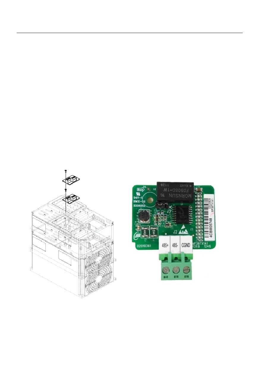
Appendix A: RS-485communication expansion
card instruction
A.1 Overview:
Especially for HV580L series frequency inverter RS485 communication, with separate solution, all
specifications are in accordance with international standard.
A.2 Installation dimension and control terminals details:
1. Dimensions are as below;
191
Appendix A: Figure1 RS485 Installation way
Appendix A: Figure 2 RS485 dimension
Terminal blocks Terminal Function:
Type Sign
Terminal
Terminal
Function
485+/485-
Communication port485 communication input terminal,
485 communication
Terminal
separate input
(CN1)
CGND
485 communication
Power is separate
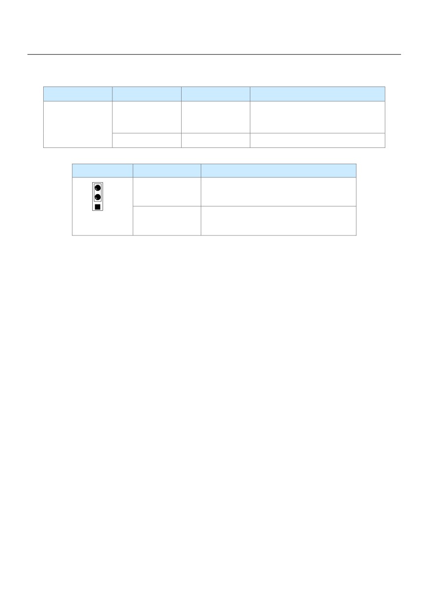
Jumper description:
J3
Jumper position
End terminal resistor
3
Short-circuit 2, 3 pinNot use end terminal resister (default)
2
Short-circuit 1, 2 pinUser end terminal resistor(white point is pin 1)
1
Cautions:
1. While using RS485 communication, if it’s the end inverter, then need to connect end resistor (Jumper J3);
2. To avoid outer interference to the communication signal, suggest use twisted-pare shielded cable on the
communication connection, avoid parallel cable.
AppendixB:HV580L Modbus communication
HV580L series inverter provides the RS485 communication interface, and support the Modbus RTU - from
standing communication protocol. Users can through the computer or PLC central control, through the
communication protocol Setting frequency converter running commands, modify or read function code
parameters, read the inverter working condition and fault information, etc.
1. Protocol content
The entire message frame must be used as a continuous stream. If the pause time frame prior to the
completion of more than 1.5 byte times, the receiving device will refresh the incomplete message and
assumes that the next byte will be the address field of a new message. Similarly, if a new message starts in
less than 3.5 bytes times following the previous message, the receiving device will consider it a continuation of
the previous message. This will set an error, as the value in the final CRC field will not be valid for the
combined messages. A typical message frame is shown below.
192
Application mode:
The inverter accessing with “single main multi-slave” PC/PLC control network, which equipped with
RS232/RS485 bus.
Bus structure:
(1)Interface mode
RS232/RS485 hardware interface
(2)Transmission mode
Asynchronous serial, half-duplex transmission. At the same time host and slave computer can only permit one
to send data while the other can only receive data. Data in the process of serial asynchronous communication
is in the message format and sent one frame by one frame.
(3)Topological mode
In single-master system, the setup range of slave address is 1 to 247. Zero refers to broadcast communication
address. The address of slave must is exclusive in the network. That is one condition of one slave machine.
Communication information structure
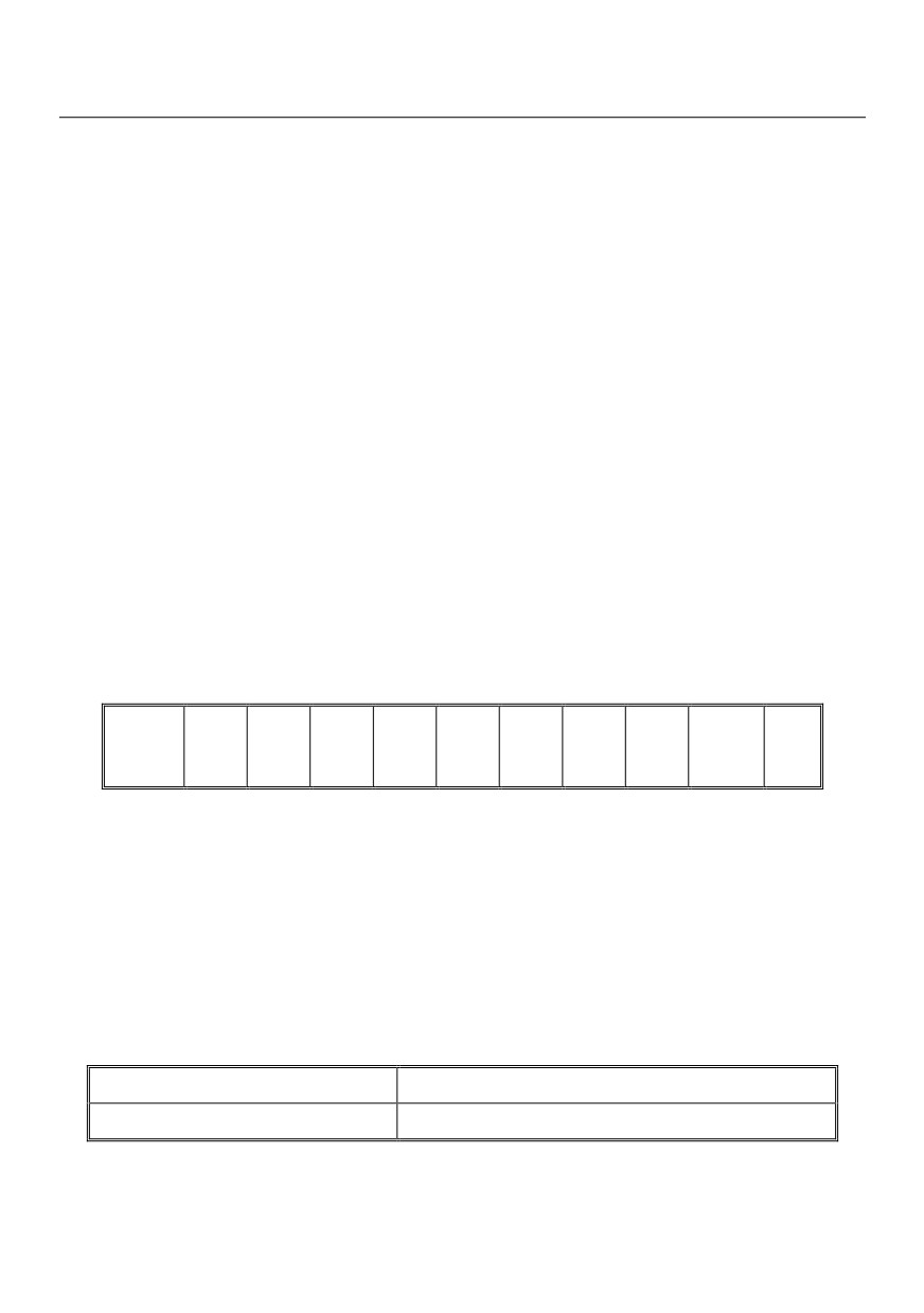
HV580L Modbus protocol communication data format is as below:
Including: starting bit, 8 data bits, parity bit and stop bit.
Starting
Parity
Stop
Bit1
Bit2
Bit3
Bit4
Bit5
Bit6
Bit7
Bit8
bit
bit
bit
The entire message frame must be used as a continuous stream. If the pause time frame prior to the
completion of more than 1.5 byte times, the receiving device will refresh the incomplete message and
assumes that the next byte will be the address field of a new message. Similarly, if a new message starts in
less than 3.5 bytes times following the previous message, the receiving device will consider it a continuation of
the previous message. This will set an error, as the value in the final CRC field will not be valid for the
combined messages. A typical message frame is shown below.
RTU frame format:
START
3.5-character time
Slave address ADDR
Communication address: 1~247
193
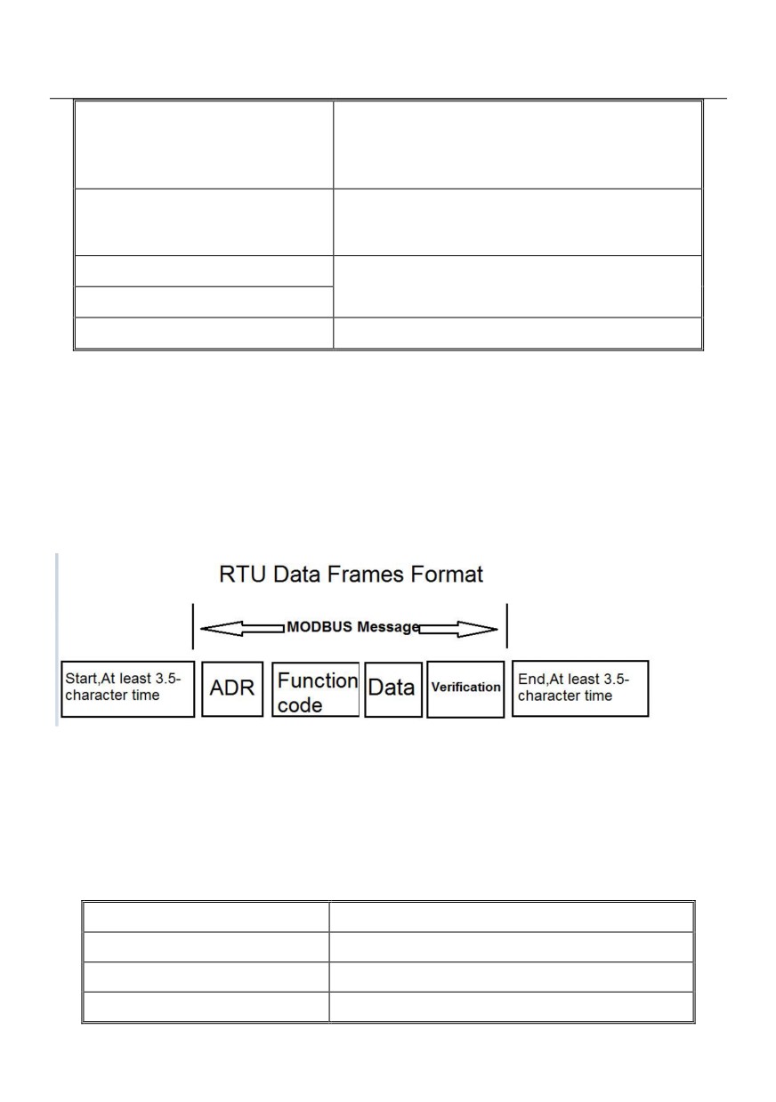
Command code CMD
03H: Read slave parameters;
06H: Write slave parameters
08H: Loop since detection
Function code parameter address, function code
DATA
parameter number, function code parameter value, etc.
CRC CHK low order
Detection value: CRC value
CRC CHK high order
END
At least 3.5-character time
In the RTU mode, a new frame to at least 3.5 bytes transmission time interval as a start. And then transfer the
data fields in the order: from the machine address, operation command code, data and CRC check words,
each domain bytes are hex 0... 9, A. F. Continuously detect network bus network facilities, including pause
interval of time. When receiving the first field (address information), each network device to decrypt the byte to
determine whether to own. A byte at the end of transmission is complete, and with a 3.5 bytes of transmission
time interval at least to indicate the end of the frame, in the later, can start a new message.
Command code and communication data description
Command code: 03H, read N (Word), maximum continuously read 12 words.
For example the inverter start address P0.02 of the slave machine address 01 continuously reads two
consecutive values.
RTU Host Commands:
ADR
01H
CMD
03H
Start address high order
P0H
Start address low order
02H
194
Register number high order
00H
Register number low order
02H
CRC CHK low order
CRC CHK values to be calculated
CRC CHK high order
RTU salve response
PD-05 set “0”:
ADR
01H
CMD
03H
Byte number high order
00H
Byte number low order
04H
Data P002H high order
00H
Data P002H low order
00H
Data P003H high order
00H
CRC CHK low order
01H
CRC CHK high order
CRC CHK values to be calculated
CRC CHK low order
PD-05 set “1”:
ADR
01H
CMD
03H
Byte number
04H
Data F002H high order
00H
Data F002H low order
00H
Data F003H high order
00H
Data F003H low order
01H
CRC CHK low order
CRC CHK values to be calculated
CRC CHK high order
Command code: 06H write a word
For example: Write 5000 (1388H) into P00AH which slave address is 02H.
RTU host commands
195
ADR
02H
CMD
06H
Data address high order
P0H
Data address low order
0AH
Data content high order
13H
Data content low order
88H
CRC CHK low order
CRC CHK values to be calculated
CRC CHK high order
RTU salve response
ADR
01H
CMD
06H
Data address high order
P0H
Data address low order
0AH
Data content high order
13H
Data content low order
88H
CRC CHK low order
CRC CHK values to be calculated
CRC CHK high order
Cyclical Redundancy Check:
Cyclical Redundancy Check—CRC mode: CRC(Cyclical Redundancy Check) is in RTU frame format,
message contains an error-checking field that is based on a CRC method. The CRC field checks the contents
of the entire message. The CRC field is two bytes, containing a 16-bit binary value. The CRC value is
calculated by the transmitting device, which appends the CRC to the message. The receiving device
recalculates a CRC during receipt of the message, and compares the calculated value to the actual value it
received in the CRC field. If the two values are not equal, then results an error. The CRC is started by 0xFFFF.
Then a process begins of applying successive 8-bit bytes of the message to the current contents of the
register. Only the eight bits of data in each character are used for generating the CRC. Start and stop bits, and
the parity bit, do not apply to the CRC.
During generation of the CRC, each eight-bit character is exclusive XOR with the register contents. Then the
result is shifted in the direction of the least significant bit (LSB), with a ZERO filled into the most significant bit
(MSB) position. The LSB extracted and examined. If the LSB is 1, the register then exclusive XOR with a
196
preset, fixed value. If the LSB is 0, no exclusive XOR takes place. This process is repeated until 8 shifts have
been performed. After the last (8) shift, the next eight-bit byte is exclusive XOR with the register’s current
value, and the process repeats for 8 more shifts as described above. The final contents of the register, after all
the bytes of the message have been applied, is the CRC value.
When CRC appended to the message, the low byte is appended first, and then the high byte.
CRC calculation program:
unsigned int crc_chk_value(unsigned char *data_value,unsigned char length)
{
unsigned int crc_value=0xFFFF;
int i;
while(length--)
{
crc_value^=*data_value++;
for(i=0;i<8;i++)
{
if(crc_value&0x0001)
{
crc_value=(crc_value>>1)^0xa001;
}
else
{
crc_value=crc_value>>1;
}
}
}
return(crc_value);
}
Communication data address definition:
The chapter is about communication contents, it’s used to control the inverter operation, the status of the
inverter and related parameter setup. Read and write function code parameters (Some function codes are not
able to be changed, only for the manufacturer use.). The mark rules of function code parameters address:
The group number and mark of function codes are parameter address for indication rules.
197

High byte: P0~PF (P group), A0~AF (A group), 70~7F (U group) Low byte: 00~FF
For example: P3.12, the address indicates 0xP30C
Caution:
Group PF: Parameters could not be read or be modified.
Group U: Parameters could be read but not be modified.
Some parameters can not be changed during operation; some parameters regardless of the kind of state the
inverter in, the parameters can not be changed. Change the function code parameters, pay attention to the
scope of the parameters, units, and relative instructions.
Besides, if EEPROM is frequently stored, it will reduce the service life of EEPROM. In some communication
mode, function code needn’t to be stored as long as changing the RAM value.
Group P: to achieve this function, change high order P of the function code address into 0.
Group A: to achieve this function, change high order A of the function code address to be 4.
Corresponding function code addresses are indicated below:
High byte: 00~0F (P group), 40~4F (A group) Low byte: 00~FF
For example:
Function code P3.12 can not be stored into EEPROM, address indicates to be 030C, function code A0-05 can
not be stored in EEPROM, address indicates to be 4005; This address can only act writing RAM, it can not act
reading, when act reading, it is invalid address. For all parameters, command code 07H can be used to
achieve this function.
Stop/run parameters:
Parameter add.
Parameter description
Parameter
Parameter description
* Communication Setting value
1000H
(decimalism)
1010H
PID setup
–10000 ~ 10000
1001H
Running frequency
1011H
PID feedback
1002H
Bus voltage
1012H
PLC process
PULSE input pulse frequency, unit
1003H
Output voltage
1013H
0.01kHz
1004H
Output current
1014H
Feedback speed, unit 0.1Hz
1005H
Output power
1015H
Rest running time
1006H
Output torque
1016H
AI1 voltage before correction
1007H
Running speed
1017H
AI2 voltage before correction
198
1008H
DI input status
1018H
AI3 voltage before correction
1009H
DO output status
1019H
Line speed
100AH
AI1 voltage
101AH
Current power on time
100BH
AI2 voltage
101BH
Current running time
PULSE input pulse frequency, unit
100CH
Running speed
101CH
1Hz
100DH
DI input status
101DH
Communication setup value
100EH
DO output status
101EH
Actual feedback speed
100FH
AI1 voltage
101FH
Main frequency X display
–
-
1020H
Auxiliary frequency Y display
Caution:
The communication setup value is percentage of the relative value, 10000 corresponds to 100.00%,-10000
corresponds to -100.00%. For data of dimensional frequency, the percentage value is the percentage of the
maximum frequency. For data of dimensional torque, the percentage is P2.10, A2.48, A3.48, A4.48 (Torque
upper digital setup, corresponding to the first, second, third, fourth motor).
Control command input to the inverter (write-only)
Command word address
Command function
0001:Forward operation
0002:Reverse operation
0003:Forward jog
2000H
0004:Reverse jog
0005:Free stop
0006:Speed-down stop
0007:Fault reset
Read inverter status: (read-only)
Status word address
Status word function
0001:Forward operation
3000H
0002:Reverse operation
0003:Stop
199
Parameters lock password check: (if the return is the 8888H, it indicates the password checksum pass)
Password address
Contents of input password
1P00H
*****
Digital output terminal control: (write-only)
Command address
Command content
BIT0:Y1 Output Control
BIT1:Y2 Output control
BIT2:RELAY1 output control
BIT3:RELAY2 output control
BIT4:Y2R output control
2001H
BIT5:VY1
BIT6:VDO2
BIT7:VDO3
BIT8:VDO4
BIT9:VDO5
Analog output AO1 control: (write-only)
Command address
Command content
2002H
0 ~ 7FFF means
0%~ 100%
Analog output AO2 control: (write-only)
Command address
Command content
2003H
0 ~ 7FFF means 0%~ 100%
(PULSE) output control:(write-only)
Command address
Command content
2004H
0 ~ 7FFF means 0%~ 100%
200

Inverter fault description:
Inverter fault address
Inverter fault information
0000:No fault
0015:Parameter read and write fault
0001:Reserved
0016:Inverter hardware fault
0002:Speed-up over current
0017:Motor earthing short-circuit
0003:Speed-down over current
fault
0004:Constant speed over current
0018:Reserved
0005:Speed-up over voltage
0019:Reserved
0006:Speed-down over voltage
001A:Running time arrive fault
0007:Constant speed over voltage
001B: User defined fault 1
0008:Buffer resistance overload
001C: User defined fault 2
fault
001D: Power on time arrive fault
0009:Under-voltage fault
001E:Load off
000A:Inverter overload
001F:PID feedback lost during
000B:Motor overload
operation
8000H
000C:Input phase lost
0028:Fast current limit timeout fault
000D:Output phase lost
0029:Motor shifting fault during
000E:Module overheating
operation
000F:External fault
002A: Excessive speed deviation
0010:Communication fault
002B:Motor over speed
0011:Contactor fault
002D:Motor over-temperature
0012:Current detection fault
005A:Encoder line number setup
0013:Motor tuning fault
fault
0014:Encoder/PG card fault
005B:Encoder not connected
005C:Initial position error
005E:Speed feedback fault
201
Pd group communication parameters description
Baud rate
Default
6005
Digital’s bit: MODBUS Baud rate
0:300BPS
5:9600BPS
1:600BPS
6:19200BPS
Pd-00
Setting range
2:1200BPS
7:38400BPS
3:2400BPS
8:57600BPS
4:4800BPS
9:115200BPS
This parameter is used to set the data transfer rate between the host computer and the inverter.
Caution: The baud rate of the position machine and the inverter must be consistent.
Or, communication is impossible. The higher the baud rate is, the faster the communication is.
Data format
Default
0
0:No check: data format <8,N,2>
Pd-01
1:Even parity check: data format <8,E,1>
Setting range
2:Odd parity check: data format <8,O,1>
3:No check: data format <8-N-1>
The data format of the position machine and the inverter setup must be consistent, otherwise communication
is impossible.
Local address
Default
1
Pd-02
Setting range
1~247,0 is broadcast address.
When the local address is set to 0, that is the broadcast address, achieve position machine’s broadcast
function. The local address is unique (except for the broadcast address), which is the basis for the position
machine and the inverter point to point communication.
Response delay
Default
2ms
Pd-03
Setting range
0~20ms
Response delay: It refers to the interval time from the inverter finishes receiving data to sending data to the
position machine. If the responses delay is less than the system processing time, the response based on the
time delay of the system processing time. If the response delay is more than the system processing time, after
the system process the data, it should be delayed to wait until the response delay time is up, then sending
data to host machine.
202
Communication overtime
Default
0.0 s
Pd-04
Setting range
0.0 s (invalid); 0.1~60.0s
When the function set to 0.0s, the communication overtime parameter is invalid.
When the function code is set to valid value, if the interval time between one communication with the next
communication exceeded the communications overtime, the system will report communication fault error (fault
serial 16= E.CoF1) . Under normal circumstances, it will be set to invalid value. If the system of continuous
communication, setting parameters, you can monitor the communication status.
Communication protocol
Default
0
selection
Pd-05
Setting range
0: non standard Modbus protocal
1: Standard Modbus Protocal
Pd.05=1: Select Standard Modbus protocol.
Pd.05=0: Reading command, the slave returns the number of bytes which has one more byte than the
standard Modbus protocol, for specific please refer to the protocol, the part of the "5 communication data
structure”.
Communication read the
Default
0
Pd-06
current resolution
Setting range
0: 0.01A; 1: 0.1A
To determine when the communication reads the output current, what the output current value unit is.
203
Warranty Agreement
1. The warranty period of the product is 18 months (refer to the barcode on the equipment). During
the warranty period, if the product fails or is damaged under the condition of normal use by
following the instructions, HNC Electric will be responsible for free maintenance.
2. Within the warranty period, maintenance will be charged for the damages caused by the
following reasons:
a. Improper use or repair/modification without prior permission
b. Fire, flood, abnormal voltage, other disasters and secondary disaster
c. Hardware damage caused by dropping or transportation after procurement
d. Improper operation
e. Trouble out of the equipment (for example, external device)
3. If there is any failure or damage to the product, please correctly fill out the Product
Warranty Card in detail.
4. The maintenance fee is charged according to the latest Maintenance Price List of HNC
Electric.
5. The Product Warranty Card is not re-issued. Please keep the card and present it to the
maintenance personnel when asking for maintenance.
6. If there is any problem during the service, contact HNC Electric’s agent or HNC Electric
directly.
7. This agreement shall be interpreted by HNC Electric Limited.
204