HSD2000 Series Servo Drive. Operation Manual V1.2 - page 6
Chapter VI Function Code Details
个位
Ones place
Tens
Ones
place
place
十位
Tens place
Operating option when a phase fails
百位
Hundreds place
0 : Protection operates when an input phase and an output
phase fail (E008/E009)
欠压故障指示动作选择
Undervoltage fault indication operating option
1: Protection does not operate when an input phase
fails
不动作
Non-operating
2: Protection does not operate when an output phase
fails
3: Protection does not operate when an input phase
动作(欠压视为故障)
Operating
(undervoltage is regarded as a
and an output phase fail
fault)
Operating option when an external analog frequency/
自动复位间隔故障指示
Automatic reset interval fault indication
torque instruction is missing
0: Non-operating
动作选择
operating option
1: Protection operates and stop freely(E022)
不动作
Non-operating
2: Give an alarm and continue
running(A022)
动作
Operating
故障锁定功能选择
Fault locking function option
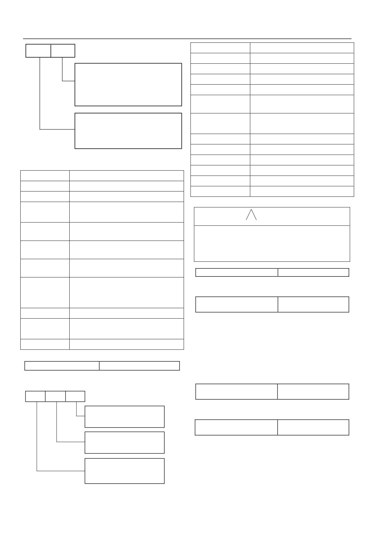
Fig.6-92 Setting of Protection Operating Option 2
禁止
Disabled
个位
Ones place
开放(故障指示不动作)
Enabled (fault indication does not operate)
十位
Tens place
开放(故障指示动作)
Enabled (fault indication operates)
缺相动作选择
Operating option when a phase fails
输入输出缺相将被
Protection operates when an input phase and an
保护
output phase fail
! Attention
输入缺相不动作
Protection does not operate when an input phase
The protection operating option function should be selected with
fails
care and it must be correctly selected after the cause of the fault
输出缺相不动作
Protection does not operate when an output phase
is determined, or else it may cause an extension of accident
fails
scope, personal injury and property damage.
输入输出均不动作
Protection does not operate when an input phase
and an output phase fail
P20.03
Reserved
外部模拟频率/转
Operating option when an external analog
Reserved function
矩指令丧失动作选
frequency/torque instruction is missing
择
P20.04 Continuing running
0~4【0】
frequency option at fault
不动作
Non-operating
0: run at current set frequency
保护动作并自由停
Protection operates and stop freely
1: run at the set frequency in P02.04 function code
车
2: run at the upper frequency limit
告警且继续运行
Give an alarm and continue running
3: run at the lower frequency limit
4: run at a standby frequency in case of an abnormity
P20.02 Fault indication option 1
000~211【000】
When function 4 is selected, it should be in combination with
P20.02 defines the protection operating option in the case
of
setting of function code P20.05
undervoltage, automatic reset interval and fault locking.
P20.05 Setting of standby
Tens
0.0~100.0%【100.0%】
Hundred
Ones place
frequency in case of an abnormity
s place
place
The setting adopts the running frequency before an abnormity as
Undervoltage fault indication operating option
maximum value 100%.
0: Non-operating
Operating (undervoltage is regarded as a
1:
P20.06 Motor overload protection
fault)
0、1、2【1】
mode option
Automatic reset interval fault indication
operating option
0: non-operating
0: Non-operating
1: Operating
There is no motor overload protection characteristic (it should be
selected with care), and here servo driver has no overload
Fault locking function option
0: Disabled
protection of load motor;
1:
Enabled (fault indication does not operate)
1: normal motor (with low-speed compensation)
2E
nabled (fault indication operates)
Because the heat dissipation effect of a normal motor is poor at a
Fig.6-93 Fault Indication Option 1
low speed, the corresponding electronic thermal protection value
is also adjusted properly. The low-speed compensation
100
Chapter VI Function Code Details
characteristic said here is to reduce the overload protection
detection level
threshold value of the motor with running frequency of less than
P20.11 Overload pre-alarm
0.0~60.0s【5.0s】
detection time
30Hz.
2: variable frequency motor (without low-speed compensation)
HSD2000 has servo driver overload protection and motor
The heat dissipation of a variable frequency motor is not affected
overload protection. For servo driver overload protection, see
by speed, so it is needless to adjust the protection value when
table 2-1; for motor overload protection, see P20.06. P20.09~
running at a low speed.
P20.11 can realize monitoring of overload condition before the
P20.07 Overvoltage stall option
0, 1【1】
overload protection operates.
P20.08 Stall overvoltage point
120~150%【140.0%】
Overload pre-alarm detection option (P20.09) defines overload
0: Disable
pre-alarm detection option, alarm operating option and relative
1: enable
value of detection level.
In the process of decelerated running of servo driver, affected by
Hundred
Tens
Ones
load inertia, actual drop rate of motor speed may be lower than
s place
place
place
drop rate of output frequency, here the motor will feed back
Overload pre-alarm detection
electric energy to servo driver, as a result that DC bus voltage of
option
0: Always detecting
servo driver rises; if a measure is not taken, overvoltage trip will
Detecting only at a constant speed
occur.
Overload pre-alarm operating
For the overvoltage stall protection function, bus voltage is
option
Give an alarm and continue
detected in the process of decelerated running of servo driver and
0:
running
it is compared with the stall overvoltage point defined in P20.08
1:Protection operates and stop
freely
(relative to standard bus voltage); if bus voltage exceeds the stall
Overload pre-alarm detection level
overvoltage point, output frequency of servo driver will stop
option
0
:Relative to rated current of motor
dropping; after bus voltage is detected again and it is lower than
1:
Relative to rated current of servo driver
the stall overvoltage point, decelerated running is implemented, as
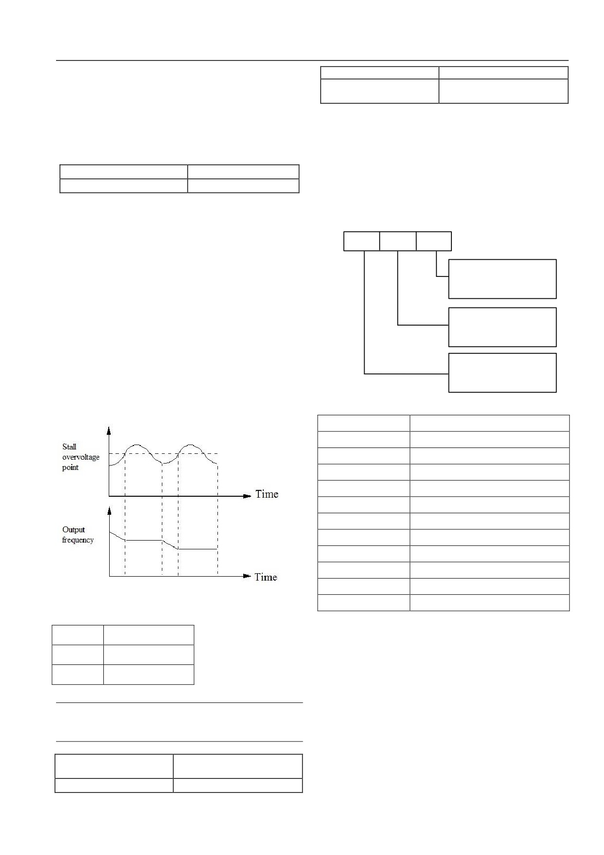
shown in Fig. 6-94.
Fig.6-95 Overload Pre-alarm Detection Option
个位
Ones place
十位
Tens place
百位
Hundreds place
过载预报警检测选择
Overload pre-alarm detection option
一直检测
Always detecting
仅恒速检测
Detecting only at a constant speed
过载预报警动作选择
Overload pre-alarm operating option
告警,继续运行
Give an alarm and continue running
保护动作并自由停机
Protection operates and stop freely
过载预报警检出量选择
Overload pre-alarm detection level option
相对电机额定电流
Relative to rated current of motor
相对驱动器额定电流
Relative to rated current of servo driver
Fig.6-94 Overvoltage Stall Function
失速过压点
Stall overvoltage point
Ones place: overload pre-alarm detection option
0: overload detection always works during running of servo
输出频率
Output frequency
driver.
时间
Time
1: overload detection works only when servo driver runs at a
constant speed.
Tens place: overload pre-alarm operating option
Attention
0: when overload detection is effective, give an alarm and
When the set stall point is lower, users are proposed to extend
the deceleration time properly.
continue running, and operating panel displays A013 or A014
according to setting of hundreds place.
P20.09 Overload pre-alarm
000~111【000】
1: when overload detection is effective, protection operates and
detection option
stop freely, and operating panel displays E013 or E014 according
P20.10 Overload pre-alarm
20~200%【130.0%】
to setting of hundreds place.
101
Chapter VI Function Code Details
Hundreds place: overload pre-alarm detection level option
run current is less than overload pre-alarm detection level,
built-in overload pre-alarm detection time will reduce
0: detection level is relative to rated current of motor (fault code
gradually up to zero.
E014).
1: detection level is relative to rated current of servo driver (fault
P20.12 Off-load protection
0~2【0】
code E013).
option
Output
P20.13 Off-load detection level
0.0~100%【30.0%】
P20.14 Off-load detection time
0.0~60.0s【1.0s】
Overload pre-alarm
Off-load protection option defines the protection operation of
detection level
servo driver in case of off-load in the torque control mode.
0: off-load protection of servo driver is disabled.
Time
1: off-load protection of servo driver is enabled.
Overload detection timing
2: Reserved.
Off-load detection level (P20.13) defines the current threshold of
Overload pre-alarm
off-load operation and its setting value is the percentage relative to
detection level
rated current of servo driver.
Off-load detection time (P20.14) defines that an off-load signal is
Time
outputted after output current of servo driver is continuously less
than off-load detection level (P20.13) for more than a certain time.
Overload detection operates
Valid
When off-load state is valid, it shows run current of servo driver is
less than off-load detection level and holding time exceeds the
Time
off-load detection time.
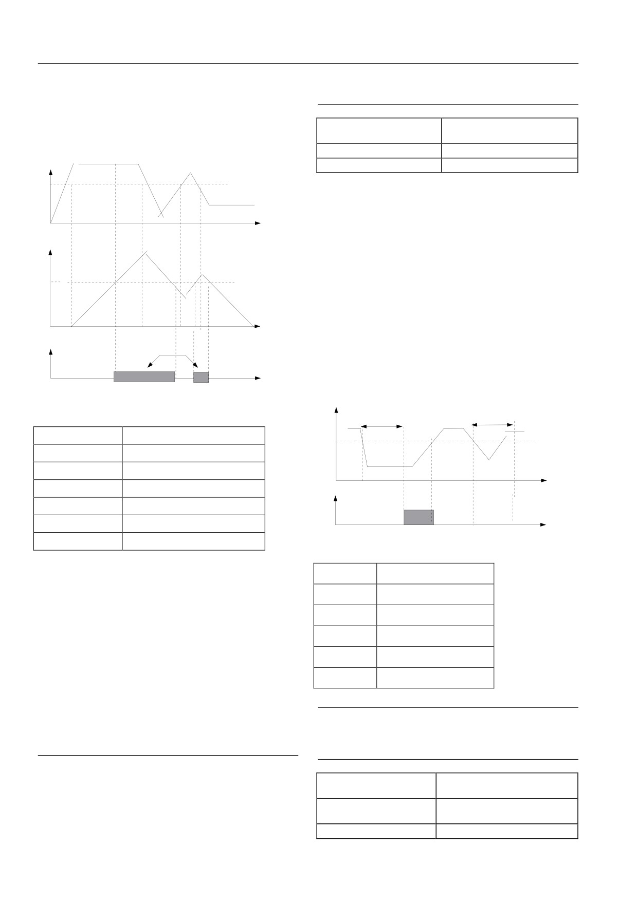
Fig.6-96 Overload Pre-alarm Detection Function Diagram
Output current
Off-load detection time
Off-load detection time
输出电流
Output
过载预报警检出水平
Overload pre-alarm detection level
Off-load detection time
过载检出计时
Overload detection timing
Time
过载检出动作
Overload detection operates
Off-load detection operation
过载预报警检出时间
Overload pre-alarm detection time
Valid
Time
有效
Valid
时间
Time
Fig.6-97 Off-Load Protection Detection Function Diagram
输出电流
Output current
Overload pre-alarm detection level (P20.10) defines the current
threshold of overload pre-alarm operation and its setting value is
掉载检出时间
Off-load detection time
the percentage relative to rated current (see P20.09).
掉载检出水平
Off-load detection level
Overload pre-alarm detection time
(P20.11) defines that an
overload pre-alarm signal is outputted after output current of servo
掉载检出动作
Off-load detection operation
driver is greater than overload detection level (P20.10) for more
有效
Valid
than a certain time.
When output current of servo driver is greater than pre-alarm
时间
Time
detection level, pre-alarm detection timing increases by degrees;
when output current of servo driver is less than detection level,
pre-alarm detection timing decreases by degrees. When overload
Attention
pre-alarm state is valid, it shows the time kept by pre-alarm
After run current is greater than off-load detection level
detection timer exceeds the overload pre-alarm detection time.
within the off-load detection time, built-in off-load detection
time will be reset.
Attention
1. Generally, setting of overload pre-alarm detection level
P20.15 Automatic current
20.0~200.0%【150.0%】
should be less than overload protection level.
limiting level
P20.16 Drop rate of frequency
2. When output current of servo driver is greater than
0.00~99.99Hz/s【10.00Hz/s】
during current limiting
detection level, pre-alarm detection timing will increase
gradually up to built-in amplitude limit. On the contrary, if
P20.17 Automatic current
0~1【1】
102
Chapter VI Function Code Details
limiting operation option
P20.20
Reserved
Reserved function
Automatic current limiting function is to automatically restrict
P20.21 Type of the first abnormity
0~50【0】
current and make it not exceed the set automatic current limiting
P20.22 Bus voltage at the moment of the
0~999V【0】
level (P20.15) through real-time control of load current, so as to
first fault
prevent the fault tripping arising from current overshoot. The
P20.23 Actual current at the moment of
0.0~999.9A【0】
function is especially applicable on the occasions that load inertia
the first fault
P20.24 Running frequency at the
is greater or load change is violent.
0.00~1000.0Hz【0.00】
moment of the first fault
Automatic current limiting level
(P20.15) defines the current
P20.25 Running state of servo driver at
threshold of automatic current limiting operation and its setting
0~FFFFH【0000】
the moment of the first fault
range is the percentage relative to rated current of servo driver.
P20.26 Type of the second abnormity
0~50【0】
Drop rate of frequency during current limiting (P20.16) defines
P20.27 Bus voltage at the moment of the
0~999V【0】
the adjustment rate of output frequency when automatic current
second fault
limiting operates.
P20.28 Actual current at the moment of
0.0~999.9A【0】
When automatic current limiting operates, if the drop rate of
the second fault
frequency (P20.16) is much lower, it does not get rid of automatic
P20.29 Running frequency at the
0.00~1000.0Hz【0.00】
moment of the second fault
current limiting state easily and an overload fault may be caused
P20.30 Running state of servo driver at
finally; if the drop rate (P20.16) is much higher, the degree of
0~FFFFH【0000】
the moment of the second fault
frequency adjustment increases and servo driver may be in the
P20.31 Type of the third abnormity
0~50【0】
power generation state for a long time, causing overvoltage
P20.32 Bus voltage at the moment of the
protection.
0~999V【0】
third fault
Automatic current limiting function is always valid in the
P20.33 Actual current at the moment of
0.0~999.9A【0】
acceleration/deceleration state. Whether automatic current limiting
the third fault
function is valid when running at a constant speed depends on
P20.34 Running frequency at the
0.00~1000.0Hz【0.00】
automatic current limiting operation option (P20.17).
moment of the third fault
P20.35 Running state of servo driver at
P20.17=0, it shows automatic current limiting function is invalid
0~FFFFH【0000】
the moment of the third fault
when running at a constant speed;
HSD2000 series have 50 kinds of abnormity protection alarms;
P20.17=1, it shows automatic current limiting function is valid
the type of the latest three abnormal faults (P20.21, P20.26 and
when running at a constant speed.
P20.31), bus voltage of servo driver at the moment of the latest
When automatic current limiting function operates, output
three faults (P20.22, P20.27 and P20.32), current at the moment of
frequency may change, so the function should not be used on the
the latest three faults (P20.23, P20.28 and P20.33), frequency at
occasions that output frequency must be relatively stable during
the moment of the latest three faults (P20.24, P20.29 and P20.34)
constant-speed running.
and running state of servo driver at the moment of the latest three
When automatic current limiting function is valid, lower setting of
faults (P20.25, P20.30 and P20.35) are memorized for users to
current limiting level may affect the overload capacity of servo
inquire.
driver.
The latest fault record is the record for the third time.
P20.18 Automatic reset
0~100【0】
For running state of servo driver, see the function code P01.17.
number
For detailed description of protection alarms and fault handling
P20.19 Automatic reset
2.0~20.0s【5.0s】
methods, see Chapter VII Measures relative Fault Alarm,
interval time
Handling of Abnormality .
Automatic fault reset function can automatically reset the running
6.1.22 Traverse operation parameter (P30 group)
fault according to the set number and interval time. When
Traverse frequency is applicable to textile and chemical fiber
automatic reset number is set as 0, it shows automatic reset is
industries and on the occasion of needing traversing and winding
disabled and fault protection is executed immediately.
functions. Typical work of traverse frequency is as shown in Fig.
Attention
6-98.
1. Inversion module protection (E010), external device fault
Generally, traverse frequency process is as below: first accelerate
(E015) and analog input overcurrent fault (E041) have no
to the preset traverse frequency (P30.02) according to acceleration
automatic reset function.
time and wait for a period of time (P30.03), next transit to center
2. During reset interval, output is locked out to run at zero
frequency according to acceleration/deceleration time, and then
run cyclically according to the set traverse frequency amplitude
frequency; after completion of automatic reset, it starts
automatically by speed tracking to run.
(P30.04), jump frequency
(P30.05), traverse frequency period
(P30.06) and traverse frequency rise time (P30.07), till a stop
3. The automatic fault reset function should be used with
command is given to slow down and stop according to
care, or else it may cause personal injury and property loss.
deceleration time.
103
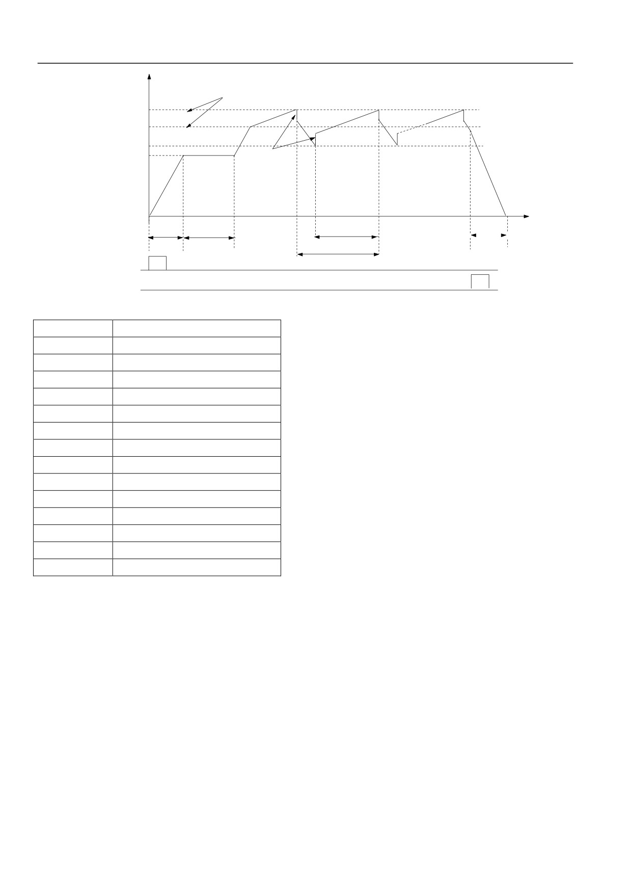
Chapter VI Function Code Details
Running frequency
Wobble frequency
amplitude
Upper wobble
Aw=Fse t *P30 . 04
frequency limit H
+Aw
Center frequency Fast
Lower wobble
-Aw
a1
frequency limit FL
Preset wobble
frequency
Textile jump
frequency
=AW*P30 .05
a1
Textile start
Triangular wave rise
Decelerat
Accelerat
Time t
waiting time
P30.06*30.0
e
e
P30.03
according
accotoing
7
Wobble
to
acceleration
frequency
deceleratio
time
period
n time
Run
command
Stop command
Fig.6-98 Traverse Frequency Diagram
运行频率
Running frequency
摆频上限频率
Upper traverse frequency limit
中心频率
Center frequency
摆频下限频率
Lower traverse frequency limit
摆频预置频率
Preset traverse frequency
运行命令
Run command
停机命令
Stop command
摆频幅度
Traverse frequency amplitude
纺织突跳频率
Textile jump frequency
按加速时间加速
Accelerate according to acceleration time
纺织启动等待时间
Textile start waiting time
三角波上升时间
Triangular wave rise time
摆频周期
Traverse frequency period
按减速时间减速
Decelerate according to deceleration time
时间
Time
104
Chapter VII Measures against Fault Alarm, Handling of Abnormality
Center frequency roots in the set frequency of normal run, multi-speed run or PLC run;
Traverse frequency is automatically cancelled in the jog and closed loop run modes.
PLC and traverse frequency run simultaneously; when switching between PLC phases, traverse frequency becomes invalid; after transition
to PLC set frequency according to acceleration/deceleration setting in PLC phase, traverse frequency starts; decelerate according to the
deceleration time in PLC phase when stopping.
P30.00 Textile function option
0~1【0】
The function decides whether to use the textile function.
0: textile function is not selected;
1: textile function is selected.
P30.01 Traverse frequency
0000~1111【0000】
run mode
The function code is used to the operating mode of traverse frequency function. Users can design programs at will according to own needs.
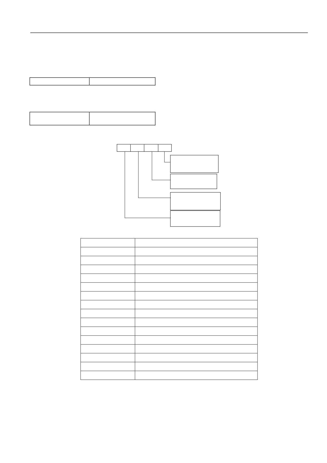
The meaning of each display place of LED is as shown in Fig.6-99.
Thousand Hundred
Tens
Ones
s place
s place
place
place
Operating mode
0 :Automatic operating mode
1: Terminal manual operating
mode
Wobble amplitude control
0:Variable wobble
amplitude
1: Fixed wobble amplitude
Wobble frequency start mode
option
0: Run in the state memorized
before stop
1:Restart
Wobble frequency state storage in case of power
down
0: Store the wobble frequency state
in case of power down
1 : Not the store
Fig.6-99 Meaning of Traverse Frequency Run Mode Parameter
个位
Ones place
十位
Tens place
百位
Hundreds place
千位
Thousands place
投入方式
Operating mode
自动投入方式
Automatic operating mode
端子手动投入方式
Terminal manual operating mode
摆幅控制
Traverse amplitude control
变摆幅
Variable traverse amplitude
固定摆幅
Fixed traverse amplitude
摆频停机起动方式选择
Traverse frequency start mode option
按停机前记忆的状态运动
Run in the state memorized before stop
重新开始起动
Restart
摆频状态掉电存储
Traverse frequency state storage in case of power down
掉电存储摆频状态
Store the traverse frequency state in case of power down
不存储
Not store the traverse frequency state in case of power down
Ones place: operating mode
0: automatic operating mode
After starting, first run for a period of time (P30.03) at the preset traverse frequency (P30.02) and then run automatically at traverse
frequency.
1: terminal manual operating mode
105
Chapter VII Measures against Fault Alarm, Handling of Abnormality
When multi-function terminal (Xi is defined as function 34) is set to be valid, it enters traverse frequency state; when invalid, it goes out of
traverse frequency state and running frequency remains at the preset traverse frequency (P30.02).
Tens place: traverse amplitude control
0: variable traverse amplitude
Traverse amplitude AW varies with center frequency and its variation rate is defined in P30.04.
1: fixed traverse amplitude
Traverse amplitude AW depends on maximum frequency and P30.04.
Hundreds place: traverse frequency start mode option
0: start in the state memorized before stop
1: restart
Thousands place: traverse frequency state storage in case of power down
Traverse frequency state parameter is stored in case of power down. The function is valid only the start mode in the state memorized
before stop is selected.
0: store the traverse frequency state in case of power down;
1: not store the traverse frequency state in case of power down.
Attention
The terminal (Xi defined as function 34) can be used to reset traverse frequency state.
P30.02 Preset traverse frequency
0.00Hz~P02.06【0.00Hz】
P30.03 Waiting time of preset
0.0~3600.0s【0.0s】
traverse frequency
P30.02 is used to define the running frequency of frequency converter before entering traverse frequency running state.
When automatic start mode is selected, P30.03 is used to set the duration of running at the preset traverse frequency before entering
traverse frequency state; when manual start mode is selected, P30.03 setting is invalid.
P30.04 Traverse
0.0%~50.0%【0.0%】
frequency amplitude
Variable traverse amplitude: AW= center frequency ×P30.04
Fixed traverse amplitude: AW= maximum running frequency P02.05×P30.04
Attention
Running frequency at traverse frequency is restricted by the upper and lower frequency limits; if it is set improperly, traverse
frequency will not work properly.
P30.05 Jump
0.0~50.0% (relative traverse amplitude)
frequency
【0.0%】
As described in Fig.6-98, when set as 0, there will be no jump frequency.
P30.06 Traverse
0.1~999.9s【10.0s】
frequency period
It defines the time of a complete period of traverse frequency rise and drop process.
Attention
It is not allowed to select automatic acceleration/deceleration run mode in the traverse frequency run mode, or else the traverse
frequency period is abnormal.
P30.07 Triangular wave rise
0~100.0%【50.0%】
time
It defines the running time (=P30.06×P30.07 (s)) of traverse frequency at the ascent stage and the running time (=P30.06×9(1-P30.07)
(s)) at the descent stage. See the description in Fig.6-98.
Attention
Users select S-curve acceleration/deceleration mode while selecting traverse frequency and traverse frequency running is
smoother.
106

Chapter VII Measures against Fault Alarm, Handling of Abnormality
6.1.23 Driver parameters (P97 group)
P97.00 Serial number
0~FFFF【6000】
P97.01 Software version number
0.00~99.99【1.00】
P97.02 Custom version number
0~9999【0】
P97.03 Rated capacity
0~999.9kVA
P97.04 Rated voltage
0~999V
P97.05 Rated current
0~999.9A
The above are the parameters of servo driver and factory defaults are set by the manufacturer.
6.1.24 Custom parameter group (P98 group)
Users can customize parameters by P98 group.
Customization details: first set the first function code parameter that a user wants to display by P98.00, next set the second function code
parameter that the user wants to display by P98.01, and so on. At most 32 custom parameters can be set.
After completion of setting, set P00.00 as 3 (user menu mode) and then press DATA/ENTER key.
If not changing P00.00 function code parameter value (set as 3), enter the function code display state; press ▲ or ▼ key, and operating
panel will only display P00.00 and custom parameters.
If a user wants to quit from custom parameter display mode, the user can enter P00.00 and change the P00.00 parameter value to a value
(not 3), and then press DATA/ENTER key.
For example, a user wants to set three custom parameters: P02.01, P03.02 and P03.00, the user can set them according to the steps as
below:
1) Use P98.00 to set the first function code parameter 02.01 and then press DATA/ENTER key;
2) Use P98.01 to set the second function code parameter 03.02 and then press DATA/ENTER key;
3) Use P98.02 to set the third function code parameter 03.00 and then press DATA/ENTER key.
4) Set P00.00 as 3 (user menu mode) and then press DATA/ENTER key.
After completion of setting, if not changing the P00.00 function code parameter value, operating panel will only display the four function
code parameters: P00.00, P02.01, P03.02 and P03.00, when entering the function code display state.
Attention
1. When a user sets a custom parameter by P98 group, if the set function code parameter is not available in the user manual of
HSD2000, setting of parameter customization will not achieve the goal.
For example, a user sets P98.01 parameter value as 02.82 and then press DATA/ENTER key, here P98.01 parameter value
displayed is 99.99.
107
Chapter VII Measures against Fault Alarm, Handling of Abnormality
Chapter VII Measures relative Fault Alarm, Handling of Abnormality
All potential faults of HSD2000 are summarized in Table 7-1. The range of fault code is E001~E041. Before seeking for service, a user can
self-examine as the table, and record phenomenon in detail. For service, please contact the seller.
Table 7-1 Details of and Measures relative Fault Alarm
Fault code
Type
Potential cause
Measure
Shorter time of acceleration
Prolong time of acceleration
Inaccurate motor parameter
Enable self-setting of motor parameter
Restart of rotating motor after instantaneous
Overcurrent
Set the start mode P05.00 to “speed tracking for restart”.
stop
during
E001
Fault of code disc during running of PG
Inspect code disc and its wiring.
acceleration of
Replace the original servo driver with one with higher
servo driver
Lower power of servo driver.
power level.
Adjust V/F curve setting and manual torque boosting
Improper V/F curve
capacity.
Overcurrent
Shorter time of deceleration
Prolong time of deceleration.
during
Potential energy or high inert torque of load
Add proper dynamic braking assembly.
E002
deceleration of
Fault of encoder during running of PG
Inspect encoder and its wiring
servo driver
Replace the original servo driver with one with higher
Lower power of servo driver.
power level
Shorter set time of acceleration/deceleration
Properly prolong time of acceleration/deceleration
Overcurrent
Sudden change or abnormality of load
Inspect load
during constant
Low grid voltage
Inspect input power.
E003
speed running of
Fault of encoder during running of PG.
Inspect encoder and its wiring
servo driver
Replace the original servo driver with one with higher
Lower power of servo driver
power level.
Overvoltage
Abnormal input voltage.
Inspect input power
during
Shorter set time of acceleration
Properly prolong time of acceleration
E004
acceleration of
Restart of rotating motor after instantaneous
Set the start mode P05.00 to “speed tracking for restart”
servo driver
stop
Overvoltage
Shorter time of deceleration (relative to
Prolong time of deceleration
during
regenerated energy)
E005
deceleration of
Potential energy or high inert torque of load
Select proper dynamic braking assembly
servo driver
Improper ASR parameter setting during
See ASR parameter setting in P07 group
Overvoltage
vector control running
during constant
Shorter set time of acceleration/deceleration
Properly prolong time of acceleration/deceleration
E006
speed running of
Abnormal input voltage
Inspect input power
servo driver
Abnormal fluctuation in input voltage
Install input reactor
High load inertia
Consider addition of dynamic braking assembly
Overvoltage of
E007
control power of
Abnormal input voltage
Inspect input power or seek for service
servo driver
Phase fault at
E008
Phase fault on input R.S.T
Inspect installation wiring and input voltage
input side
Phase fault at
Inspect output wiring,
E009
Phase fault on output U.V.W
output side
motor and cable
Inter-phase short circuit or grounded short
Power module
Re-wiring; confirm good state of motor insulation
E010
circuit among 3 output phases
protection
Instantaneous overcurrent of servo driver
See the measures relative overcurrent
108
Chapter VII Measures against Fault Alarm, Handling of Abnormality
Fault code
Type
Potential cause
Measure
Blocking of air duct, damage of fan
Unblock air duct or replace fan
Higher ambient temperature
Lower ambient temperature
Looseness of wiring or plug-in of control
Inspect whether re-wiring is needed
panel
Abnormal current waveform due to output
Inspect wiring
phase fault
Damage of auxiliary power and
Seek for service
undervoltage of driver
Shoot-through of bridge arm of inverter
Seek for service
module
Abnormality of control panel
Seek for service
Higher ambient temperature
Lower ambient temperature
Overheat of heat
Blocking of air duct
Clean air duct
E011
radiator of
Damage of fan
Replace fan
inverter module
Abnormality of inverter module
Seek for service
Overheat of heat
Higher ambient temperature
Lower ambient temperature
E012
radiator of
Blocking of air duct
Clean air duct
rectifier module
Damage of fan
Replace fan
Enable self-setting of motor parameter
Inaccurate motor parameter
Replace the original servo driver with one with higher
Higher load
power
Overload of
DC over-braking
Reduce DC brake current and prolong time of braking
E013
servo driver
Restart of rotating motor after instantaneous
Set the start mode P05.00 to “speed tracking for restart”
stop
Shorter time of acceleration
Prolong time of acceleration
Lower grid voltage
Inspect grid voltage
Improper V/F curve
Adjust V/F curve and torque boosting capacity
Incorrect setting of motor overload
Correctly set motor overload protection factor
protection factor
Blocking of motor or excess of sudden
Inspect load.
Overload of
change in load
E014
motor
Long-time low-speed running of universal
Select special motor for long-time low-speed running
motor under heavy load
Lower grid voltage
Inspect grid voltage
Improper V/F curve
Correctly set V/F curve and torque boosting capacity
Emergency stop
See the functional definition of the key “STOP” in
The key “STOP” pressed;
or fault of
P00.06.
E015
external
Effectiveness of external emergency stop
After cancellation of external fault, release external
equipment
terminal
emergency stop terminal
Read-write fault
E016
Error in read-write of control parameter
Press STOP/RESET for reset or seek for service
of EEPROM
Improper setting of Baud rate
Set Baud rate as appropriate
Abnormal
Communication error at serial port
Press STOP/RESET for reset or seek for service
E017
communication
Improper setting of fault alarm parameter
Modify settings in P18.03 and P20.00
at serial port
Inspect whether upper computer is active and its wiring is
Inactiveness of upper computer
correct
Lower grid voltage
Inspect grid voltage
Damage of contactor
Replace contactor of main circuit or seek for service
Abnormality of
E018
Damage of power-on buffer resistor
Replace buffer resistor or seek for service
contactor
Damage of control circuit
Seek for service
Phase fault of input
Inspect input R.S.T wiring
109
Chapter VII Measures against Fault Alarm, Handling of Abnormality
Fault code
Type
Potential cause
Measure
Looseness of wiring or plug-in of control
Inspect whether re-wiring is needed
panel
Abnormality of
Damage of auxiliary power
Seek for service
E019
current detection
Damage of Hall device
Seek for service
circuit
Abnormality of amplifying circuit
Seek for service
Higher AI analog input voltage
Reduce AI analog input voltage to a level below 12V
Press STOP/RESET for reset or add power filter at power
Severe interference
System
input side
E020
interference
Wrong read-write of DSP on main control
Press STOP/RESET for reset or seek for service
panel
Parameter loss during feedback or improper
Loss of
Modify setting in P13.37.
setting of feedback
E021
closed-loop
Disconnection of feedback
Re-wiring
feedback
Lower closed-loop feedback setting
Increase feedback setting in reference to setting in P13.02
Disconnection of analog demand signal
Loss of external
under main frequency setting or analog
E022
Inspect wiring or adjust input type of setting signal.
setting command
current setting selected by torque command,
or lower analog demand signal (<2mA)
Error of
Incomplete parameters of operation panel,
Refresh data and version of operation panel; upload
parameter
dismatch between versions of operation
parameter by setting P00.05 as 1, and then download
E023
copying on
panel and main control panel
parameter by setting P00.05 as 2 or 3
operation panel
Damage of EEPROM on operation panel
Seek for service
Wrong setting of parameters specified on
Set parameters in accordance with nameplate of motor
nameplate of motor
Reverse rotation (for self-setting) during
Cancel prohibition of reverse rotation
E024
Bad self-setting
prohibition of reverse rotation
Inspect motor wiring
Overtime of self-setting
Inspect whether setting of P02.06 (upper limit of
frequency) is lower than the rated value
Control with PG vector or PG V/F,
E025
Fault of PG
Re-wire encoder when necessary
disconnection of encoder signal
Load fault of
Loss or reduction of load
Inspect load
E026
servo driver
Improper setting of load fault protection
Set parameters of load fault protection as appropriate
Fault of brake
E027
Damage of brake pipe
Seek for service
unit
Cancel servo control or modify servo control to
Running of servo control under open-loop
closed-loop vector mode;, confirm correctness of encoder
vector mode
Error of
parameter
E028
parameter
For vector control, prevent torque limit (P08.08, P08.09)
setting
and frequency setting (stage frequency setting of P02.08,
Wrong setting of closed-loop process call
P13.00 or PLC) from being simultaneously established in
closed-loop process
Short circuit of
Short circuit between P24 and terminal
Confirm correct connection between P24 and COM
E029
24V power of
COM
control panel
Damage of interface board circuit
Replace interface board or seek for service
E030~
Reserved
E033
Improper ASR parameter
Modify function code in P07 group
Over-deviation
E034
Lower DEV detection value
Modify setting of DEV detection value
(DEV)
Sharp fluctuation of load
Elimanate load shake
Disconnection of encoder
Inspect encoder wiring
E035
Overspeed (OS)
Incorrect encoder parameter setting
Reset encoder parameters
110
Chapter VII Measures against Fault Alarm, Handling of Abnormality
Fault code
Type
Potential cause
Measure
Lower overspeed detection value
Modify setting of overspeed detection value
E036~
Reserved
E040
Input
Abnormality of control circuit
Seek for servicfe
E041
overcurrent of
Higher input current
Inspect analog current input
CCI
E042~
Reserved
E045
Attention
Short circuit of brake resistor on the servo driver can cause damage to brake unit of the servo driver.
All potential alarms of HSD2000 are shown in Table 7-2 (for detail, see the settings of function codes in P20 group). If fault automatically
disappears during running, the servo driver will automatically recover to the pre-alarm state, except A017 (for detail, see the note on
function codes in P20 group).
Table 7-2 Details of and Measures relative Alarm
Alarm code
Type
Potential cause
Measure
Inaccurate motor parameter
Enable self-setting of motor parameter
Replace the original servo driver with one with higher
Higher load
power
DC over-braking
Reduce DC brake current and prolong time of braking
Overload of
A013
Restart of rotating motor after instantaneous
servo driver
Set the start mode P05.00 to “speed tracking for restart”
stop
Shorter time of acceleration
Prolong time of acceleration
Lower grid voltage
Inspect grid voltage
Improper V/F curve
Adjust V/F curve and torque boosting capacity
Incorrect setting of motor overload
Correctly set motor overload protection factor
protection factor
Blocking of motor or excess of sudden
Inspect load
Overload of
change in load
A014
motor
Long-time low-speed running of universal
Select special motor for long-time low-speed running
motor under heavy load
Lower grid voltage
Inspect grid voltage
Improper V/F curve
Correctly set V/F curve and torque boosting capacity
Read-write fault
A016
Error in read-write of control parameter
Press STOP/RESET for reset or seek for service
of EEPROM
Improper setting of Baud rate
Set Baud rate as appropriate
Abnormal
Communication error at serial port
Press STOP/RESET for reset or seek for service
A017
communication
Improper setting of fault alarm parameter
Modify settings in P18.03 and P20.00
at serial port
Inspect whether upper computer is active and its wiring is
Inactiveness of upper computer
correct
Lower grid voltage
Inspect grid voltage
Damage of contactor
Replace contactor of main circuit or seek for service
Abnormality of
Damage of power-on buffer resistor
Replace buffer resistor or seek for service
A018
contactor
Damage of control circuit
Seek for service
Phase fault of input
Inspect input R.S.T wiring
Parameter loss during feedback or improper
Loss of
Modify setting in P13.37.
setting of feedback
A021
closed-loop
Disconnection of feedback
Re-wiring
feedback
Lower closed-loop feedback setting
Increase feedback setting in reference to setting in P13.02
111
Chapter VII Measures against Fault Alarm, Handling of Abnormality
Alarm code
Type
Potential cause
Measure
Disconnection of analog demand signal
Loss of external
under main frequency setting or analog
A022
Inspect wiring or adjust input type of setting signal
setting command
current setting selected by torque command,
or lower analog demand signal (<2mA)
Short circuit of
Short circuit between P24 and terminal
Confirm correct connection between P24 and COM.
A029
24V power of
COM
control panel
Damage of interface board circuit
Replace interface board or seek for service
! Attention
The function of fault alarm shall be enabled with caution, otherwise accident can spread and cause personal injury and property
damage.
Table 7-3 Abnormality in Operation and Measure
Phenomenon
Detail
Potential cause
Measure
In out-of-service state or state of running
parameter, keep down the key
The function of operation panel locking is
“DATA/ENTER”, and then press the key
enabled.
“▼” for 3 continuous times for unlocking
No response
Individual or all keys fail to
Re-connect power supply of servo driver
on operation
respond.
after full power-down
panel
Poor contact of connecting wire of operation
Inspect connecting wire by re-hot-plug
panel
Replace operation panel or seek for
Damage of key of operation panel
service
Modification fault in
The function code is non-modifiable in
Modify the function code in out-of-service
running state
running state.
state
The function code P00.03 is set as “1” or “2”.
Modify P00.03 to 0
Part of function codes are
User is not allowed to modify measured
non-modifiable.
The function code is measured value.
Function code
value of function code.
modification
No response is given by
The function of operation panel locking is
See the solution for “no response on
fault
pressing MENU/ESC.
enabled; other cause
operation panel”
Modification can’t be
Input correct user password
entered by pressing
User password required
MENU/ESC, and function
Seek for service
code is displayed as “0000”.
Fault alarm
Find cause of and clear fault
Simple PLC single cycle completed
Inspect parameter setting of PLC
Interruption of power supply
Inspect power supply
Without stop command,
Inspect setting of function code related to
servo driver automatically
Switching of running command channel
operation and running command channel
stops and running indicator
Speed over-deviation (DEV)
Modify setting of DEV detection value
Accidental
lamp goes out.
OS
Modify setting of OS detection value
stop of servo
Change in positive and negative logic of
driver during
Inspect conformity of setting in P10.16
control terminal
running
Inspect setting of automatic fault recovery
Without stop command,
Automatic fault recovery
and cause of fault
motor automatically stops
Simple PLC pause
Inspect PLC pause terminal
and servo driver runs at zero
Inspect setting of external interruption and
frequency with brightness
External interruption
fault source
of running indicator.
Frequency setting of 0
Inspect frequency setting
112
Chapter VII Measures against Fault Alarm, Handling of Abnormality
Phenomenon
Detail
Potential cause
Measure
Start frequency is higher than frequency
Inspect start frequency
setting
Improper setting of hopping frequency
Inspect setting of hopping frequency
Negative closed-loop output during
Inspect settings in P13.35 and P05.12
prohibition of reverse rotation
Enablement of the terminal “no forward
Inspect setting of terminal function
rotation” during forward rotation
Enablement of the terminal “no reverse
Inspect setting of terminal function
rotation” during reverse rotation
“Frequency adjustment”= 0
Inspect settings in P02.12 and P02.13
Instantaneous LV compensation at restart
Inspect setting of the function “restart
after power outage, lower power voltage
after power outage” and input voltage
Effectiveness of free stop terminal
Inspect free stop terminal
Effectiveness of running prohibition terminal
Inspect running prohibition terminal
Effectiveness of external stop terminal
Inspect external stop terminal
Opening of three-wire running control
Set and close three-wire running control
terminal under three-wire control mode
terminal
Servo driver doesn’t run,
Remove the fault
Running fault
and running indicator lamp
Fault alarm
of servo driver
is inactive after running key
Cancel the function of upper computer
is pressed.
Improper setting of upper computer analog
analog terminal, or offer proper setting
terminal
with upper computer, or modify setting in
P10.17.
Improper setting of positive and negative
Inspect setting in P10.16
logic of input terminal
The alarm
“P.oFF”
Since contactor is unclosed, DC bus voltage
immediate
of main circuit will fall when servo driver
Contactor is opened, and
Put servo driver into running after full
after
runs under high load. Servo driver first
load on servo driver is high.
closing of contactor
connection of
doesn’t display the fault E018 but displays
power supply
“P.oFF”.
of servo driver
113
Chapter IX Functional Code List
Chapter VIII Servicing and Maintenance
Potential fault of the servo driver can occur due to any of ambient temperature, humidity, dust, vibration and ageing or wear of internal
components of servo driver. Given this, it is necessary to maintain the servo driver daily and regularly.
Attention
1. Before inspection or maintenance, the items below shall be confirmed, otherwise electric shock can occur.
2. Power supply of the servo driver has been disconnected.
3. The charge indicator lamp will go out when cover plate is opened.
4. The voltage measured with DC HV voltmeter between (+) and (-) is lower than 36V.
8.1 Daily servicing and maintenance
The servo driver must run in the service environment specified in 2.1. Accidents can occur during running. Daily maintenance shall be
carried out as the table below. Keeping good running environment, recording data about daily running and finding cause of abnormality as
soon as possible are favorable to prolonging service life of the servo driver.
Table 8-1 Prompt on Daily Inspection
Essentials
Object
Standard
Content
Interval
Method
Temperature and
Thermometer and
Derating under the temperature range -10℃
humidity
hydrometer
~+40℃ or 40℃~50℃,
Service
Dust, water and
Anytime
environment
Visual inspection
No sign of water leak
leak
Gas
Olfactory inspection
No odor
Shake and heat
Touch on shell
Stable vibration and reasonable air temperature
Servo driver
Anytime
Noise
Audible inspection
No abnormal sound
Heat
Touch
No abnormal heat
Motor
Anytime
Noise
Audible inspection
Even noise
Output current
Ammeter
Current within the range of rated value
Running
state
Output voltage
Voltmeter
Voltage within the range of rated value
Anytime
parameter
Internal
Thermometer
Temperature lower than 35℃
temperature
8.2 Regular maintenance
With a view to service environment, the servo driver can be inspected once 3 or 6 months.
Attention
1.Only one that has passed professional training can undertake removal of component, maintenance and replacement of device.
2.Metals such as screw and washer shall not be left in the servo driver, otherwise damage can be caused to the servo driver.
Common contents of inspection
1. Whether screw of the control terminal is loose (if the screw is loose, tighten it with screwdriver)
2. Whether there’s poor contact on terminal of the main circuit or sign of overheat at connection of the copper bar.
3. Whether there’s damage of power cable or control cable especially sign of cut on sheath in contact with metal surface
4. Whether insulating binding tape of power cable nose has fallen off.
5. Fully clear dust on circuit board and air duct with dust collector
6. A servo driver stored for long term must be energized once within 2 years, for 5h at least. In this process, voltage shall be slowly
increased to the rated value with voltage regulator. During the increase, the servo driver can be unloaded.
114

Chapter IX Functional Code List
7. For insulation test of the servo driver, all input and output terminals (R, S, T, U, V, W, PE, P1, +, -) of the main circuit must be
short-circuited and grounded for test. A terminal mustn’t be individually grounded for test, otherwise damage can be caused to the
servo driver. For the test, 500V megameter shall be used.
8. For insulation test of the motor, input terminals (U, V, W) of the motor must be removed from the servo driver, and the motor shall be
independently tested, otherwise damage can be caused to the servo driver.
Attention
1. Before delivery, withstand voltage test has been carried out. It is unnecessary for user to newly carry out withstand voltage test.
Improper test can damage the device.
2. The element for replacing an original element must be the same model with the same electrical parameters, otherwise damage
can be caused to the servo driver.
8.3 Replacement of quick-wear parts of servo driver
Quick-wear parts of the servo driver are cooling fan and filter electrolytic capacitor. Their lives are tightly associated with service
environment and situation of maintenance. Their common lives are shown in the table below.
Table 8-2 Life of Component
Name of device
Life
Fan
30000~40000h
Electrolytic
40000~50000h
capacitor
Relay
100000 times
A user can establish replacement interval according to running time.
1. Cooling fan
Potential cause of damage: wear of bearing, ageing of blade
Standard: whether there’s crack on blade or sound of abnormal vibration at start
2. Filter electrolytic capacitor
Potential cause of damage: high ambient temperature, increase in pulsating current due to frequent load hopping, ageing of electrolyte
Standard: whether there’s leakage of liquid or protrusion of safety valve, measurement of electrostatic capacity, measurement of
insulation resistance
3. Relay
Potential cause of damage: corrosion, frequent action
Standard: opening/closing fault
8.4 Storage of servo driver
For temporary or long-term storage of the servo driver, attention must be paid to those below.
1. The servo driver shall not be stored where there’s high temperature, humidity, dust or metal dust. The place for storing the servo driver
shall be well ventilated.
2. Long-term storage can worsen electrolytic capacitor. Given this, for long-term storage, the servo driver must be energized once within 2
years, for 5h at least. In this process, voltage must be slowly increased to the rated value with voltage regulator.
8.5 Maintenance of servo driver
In any of the circumstances below, we will undertake repair.
1. The scope of warranty only refers to body of the servo driver.
2. For fault or damage occurring during normal service of the servo driver, the manufacturer will undertake repair within 18 months as of
the date of delivery. Anytime out of the 18 months, proper maintenance cost will be collected.
3. In any of the circumstances below, proper maintenance cost will be collected even within the 18 months.
1)Damage due to operation in violation of the user manual
2)Damage due to fire disaster, flood or abnormal voltage
3)Damage due to application of the servo driver for abnormal purpose.
4. Related service fee will be collected as actually incurred. If there’s an agreement concerned, the agreement shall prevail.
115
Chapter IX Functional Code List
Chapter IX Functional Code List
Parameters of HSD2000 series servo driver is grouped by function including 25 units as P00-P19, P20,P30 and P97-P99, each group
contain some functional codes which adopt “functional group number +function code” for grouping, samples as P XX.YZ given in the
manual mean: the YZ functional code in the XX group, for example, P10.26 means that 26th functional code in the 10th group.
Introduction to the structure of functional code list:
Table 9-1 Introduction to the structure of functional code list
Line
Name
Description
1
Functional code
Number of functional parameter group and parameters
2
Name
Full name of functional parameters
3
LCD display
Functional parameter name is simply shown through LCD on the panel
4
Setting scope
Valid setting scope for functional parameters, shown through LCD on the panel
5
Min unit
Min unit for setting functional parameters
6
Factory default
Original value of functional parameters set in factory
Change of functional parameters (allow to change or not and conditions for any change)
“○”: means the parameter can be changed when the servo drive is kept in stop and running;
“×”: means the parameter cannot be changed when the servo drive is kept in running;
“*”: means the parameter cannot be changed when it is the actual test value;
7
Change
“--”: means the parameter is “factory default” to be set by the factory only, and the user is forbidden to
change.
(The servo drive has make automatic check limit to the change of parameters so as to prevent from
improper change by the user)
Note:
1. Parameter systems adopt decimal system (DEC) and hexadecimal system (HEX), if the HEX is used, each data in editing shall be
kept independent and some values can adopt HEX (0-F).
2. LCD display in the table is available for LCD Chinese/English operation panel only.
3. “Factory default” means when the user selects the factory default, the functional code parameters will brush the value, but actually
tested parameters or record values will not be brushed.
Table 9-2 Functional Code List
Group P00: System Management
Functio
Min
Chang
nal
Name
LCD Display
Setting Scope
Default
Unit
e
Code
0: Shortcut menu: display only parameters related
to the shortcut operation of servo driver;
1: Basic menu: display only basic functional
parameters
Menu mode
P00.00
Menu mode option
2: Advanced menu: display all parameters;
1
2
○
option
3: User menu: display only 32 parameters that the
user set in P98;
4: Proof menu: display only parameter groups
differing from the default.
0: Chinese
LCD language
Language
P00.01
1: English
1
0
○
option
option
2~4: Reserved
0: No password
P00.02
Password
Password
1
0
○
Other: Password needed
0: Able to change all data;
Parameter
Parameter
1: Not allow to change except this functional code
P00.03
protection
1
0
○
protection setting
and main frequency setting P02.04.
setting
2: Not allow to change except this functional code
116
Chapter IX Functional Code List
Group P00: System Management
Functio
Min
Chang
nal
Name
LCD Display
Setting Scope
Default
Unit
e
Code
0: Parameter changed
1: Remove fault memory
Parameter
Parameter
P00.04
2: Restore to the default
1
0
×
initialization
initialization
3: Restore only the quick start functional group
4: Restore only the user-set parameter group
0: No action
1: Parameter upload to the keyboard
2: Parameter download to the drive
P00.05
Parameter copy
Parameter copy
3: Parameter download (excluding motor
1
0
×
parameters)
Note: No upload/download to the servo driver
parameters.
LED ones place: STOP key function option
0: Invalid for non-panel control
1: Press the “stop machine” to stop for non-panel
operation
2: Free to stop for non-panel operation
Report E015
LED tens place: LOCAL key function option
0: Invalid
1: Valid for machine stop status
Key function
2: Valid for machine running or stop
P00.06
Key function option
1
0000
×
option
LED Hundreds place: Operation panel lock
0: No lock
1: All locked
2: All locked except STOP key
3: All locked except SHIFT key
4: All locked except RUN, STOP keys
LED thousands place: double-click STOP key for
emergent stop
0: double-click STOP key for free stop
1: No function
Group P01: Status Display Parameters
Functio
Chang
nal
Name
LCD Display
Setting Scope
Min Unit
Default
e
Code
0: Invalid
1: Digit given 1: Operation panel▲,▼Given
2: Digit given2: Terminal UP/DOWN given
Main setting
Main setting
P01.00
3: Digit given 3: Serial port given
1
0
frequency channel
frequency channel
4: AI mode given
5: Terminal PULSE given
6: Reserved
Main given setting
Main given setting
P01.01
-1000.0~1000.0Hz
0.01Hz
0.00
frequency
frequency
Auxiliary given
Auxiliary given
P01.02
-1000.0~1000.0Hz
0.01Hz
0.00
setting frequency
setting frequency
P01.03
Setting frequency
Setting frequency
-1000.0~1000.0Hz
0.01Hz
0.00
P01.04
Frequency
Frequency
-1000.0~1000.0Hz
0.01Hz
0.00
*
117
Chapter IX Functional Code List
Group P01: Status Display Parameters
Functio
Chang
nal
Name
LCD Display
Setting Scope
Min Unit
Default
e
Code
instruction(after
instruction
Acc or Dec)
P01.05
Output frequency
Output frequency
-1000.0~1000.0Hz
0.01Hz
0.00
P01.06
Output voltage
Output voltage
0~480V
1V
0
P01.07
Output current
Output current
0.0~3Ie
0.1A
0.0
P01.08
Torque current
Torque current
-300.0%~+300.0%
0.1%
0.0%
P01.09
Flux current
Flux current
0.0%~+100.0%
0.1%
0.0%
P01.10
Output torque
Output torque
-300.0%~+300.0%
0.1%
0.0%
0.0%~200.0%(relative rated power of the
P01.11
Motor power
Motor power
0.1%
0.0%
motor)
Motor estimate
Estimated motor
P01.12
-600.00~600.00Hz
0.01
0.00
frequency
frequency
Motor measured
Motor measured
P01.13
-600.00~600.00Hz
0.01
0.00
frequency
frequency
Energy
Energy
10000kW
P01.14
consumption high
consumption high
0~65535*10000kWh
0
h
bit(kWh)
bit (kWh)
Energy
Energy
P01.15
consumption low bit
consumption low
0~9999kWh
1kWh
0
(kWh)
bit (kWh)
P01.16
Bus voltage
Bus voltage
0~800V
1V
0
0~7FFFH
BIT0: Run/Stop
BIT1: Reverse/Forward
BIT2: Zero speed run
BIT3: Accelerate
BIT4: Decelerate
BIT5: Constant speed run
BIT6: Pre-excitation
Servo driver
Servo driver
P01.17
BIT7: Setting
1
0
running status
running status
BIT8: Over current limit
BIT9: DC over voltage limit
BIT10: Torque limit
BIT11: Speed limit
BIT12: Servo driver fails
BIT13: Speed control
BIT14: Torque control
BIT15: Place control
Digital input
P01.18
DI terminal status
0~3FFH, 0: off; 1: on
1
000
terminal status
Digital output
P01.19
DO terminal status
0~FH, 0: off; 1: on
1
0
terminal status
P01.20
AI1 input voltage
AI1 input voltage
-10.00~10.00V
0.01V
0.00
P01.21
AI2 input voltage
AI2 input voltage
-10.00~10.00V
0.01V
0.00
P01.22
AI3 input voltage
AI3 input voltage
-10.00~10.00V
0.01V
0.00
Adjusted AI1
P01.23
Adjusted AI1 input
-10.00~10.00V
0.01V
0.00
input
Adjusted AI2
P01.24
Adjusted AI2 input
-10.00~10.0V
0.01V
0.00
*
input
118
Chapter IX Functional Code List
Group P01: Status Display Parameters
Functio
Chang
nal
Name
LCD Display
Setting Scope
Min Unit
Default
e
Code
Adjusted AI3
P01.25
Adjusted AI3 input
-10.00~10.00V
0.01V
0.00
input
P01.26
AO1 output
AO1 output
0.0~100.0%( percent relative full range)
0.1%
0.0%
P01.27
AO2 output
AO2 output
0.0~100.0%( percent relative full range)
0.1%
0.0%
Process close-loop
Process close-loop
-100.0~100.0%( percent relative full
P01.28
0.1%
0.0%
given
given
range)
Process close-loop
Process close-loop
-100.0~100.0%( percent relative full
P01.29
0.1%
0.0%
feedback
feedback
range)
Process close-loop
Process close-loop
-100.0~100.0%( percent relative full
P01.30
0.1%
0.0%
error
error
range)
Process close-loop
Process close-loop
-100.0~100.0%( percent relative full
P01.31
0.1%
0.0%
output
output
range)
Radiator1
Radiator1
P01.32
0.0~150.0℃
0.1℃
0.0
temperature
temperature
Radiator2
Radiator2
P01.33
0.0~150.0℃
0.1℃
0.0
temperature
temperature
P01.34
Reserved
Reserved
P01.35
Reserved
Reserved
Power on hours
Power on hours
P01.36
0~max65535 hours
1 hour
0
accumulated
accumulated
Run hour
Run house
P01.37
0~max65535 hours
1 hour
0
accumulated
accumulated
Fan run hour
Fan run hour
P01.38
0~max65535 hours
1 hour
0
accumulated
accumulated
P01.39
Reserved
Reserved
ASR controller
ASR controller
-300.0~300.0%(Rated torque relative
P01.40
0.1%
0.0%
output
output
motor)
-300.0~300.0%(Rated torque relative
P01.41
Torque given
Torque given
0.1%
0.0%
motor)
P01.42
Reserved
Reserved
Position loop given
P01.43
Given high bit
0~FFFFH
1
0
high bit
Position loop given
P01.44
Given low bit
0~FFFFH
1
0
low bit
Position loop
Feedback high
P01.45
feedback high
0~FFFFH
1
0
position
position
Position loop
Feedback low
P01.46
feedback low
0~FFFFH
1
0
position
position
P01.47
Position error pulse
Position error
-9999~9999
1
0
P01.48
Reserved
Reserved
Reserved
-
-
P01.49
~P01.5
Reserved
Reserved
Reserved
-
-
*
7
119