HSD2000 Series Servo Drive. Operation Manual V1.2 - page 5
Chapter VI Function Code Details
Tens
Ones
Cont
place
place
Corresponding function
Indication range
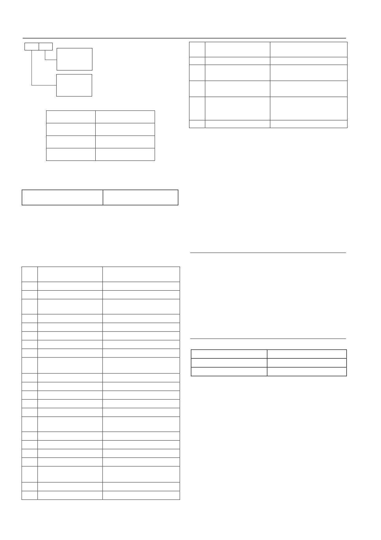
AO1output type option
ent
0: 0:
10V
1: 0:
20mA
motor
2: 2:
10V
3: 4:
20mA
Output torque current
-300~300%rated torque of
22
AO2output type option
(bipolarity)
motor
0: 0:
10V
1: 0:
20mA
-300~300%rated torque of
2: 2:
10V
23
Torque bias (bipolarity)
3: 4:
20mA
motor
Negative maximum output
Fig.6-52 Analog Output Type Option
24
Motor speed (bipolarity)
frequency ~maximum output
十位
Tens place
frequency
25
Reserved
Reserved
个位
Ones place
AO1 输出类型选择
AO1 output type option
For extended function 2 of upper computer, output of AO1 and
AO2 is directly controlled by serial port. 4095 corresponds to
AO2 输出类型选择
AO2 output type option
maximum output 10V (20mA), refer to HSD2000 communication
protocol.
The function code is used to select the analog output range of
For example,
AO1 and AO2.
AO1 output 4~20mA corresponds to indicating bus voltage 0~
P11.17 Output function option of
800V.
0~25【0】
AO1 terminal
Setting is as below:
For output characteristics of AO1 and AO2, see 4.2 control circuit
①P11.17=8, output bus voltage;
wiring and configuration; analog output range is determined by
②P11.16=03, AO1 output type is 4~20mA;
the function code P11.16.
The linear correspondence relation between AO1 output and
③P11.19=100%, output gain is 100%
indication range is as shown in table 6-14.
④P11.20=0, zero-bias correction is 0.
Table 6-14 Indication of Analog Output Terminal
Attention
1. When the corresponding function of AO output is
Cont
Corresponding function
Indication range
ent
unipolarity
(P11.17 = 0 ~ 20), absolute value of the
corresponding indication of minimum output is minimal and
0
Output frequency
0~maximum output frequency
absolute value of the corresponding indication of maximum
1
Set frequency
0~maximum output frequency
output is maximal; when the corresponding function is
Set frequency (after
bipolarity (P11.17=21~24), the corresponding indication of
2
0~maximum output frequency
acceleration/deceleration)
minimum output is minimal and the corresponding indication
3
Motor speed
0~maximum speed
of maximum output is maximal.
4
Output current
0~2×rated current of servo driver
2. When AO output is current, it is suggested that external
5
Output current
0~2×rated current of motor
equivalent resistance should not exceed 400Ω.
6
Output torque
0~3×rated torque of motor
7
Output torque current
0~3×rated torque of motor
P11.18 AO1 output filter
0.0~20.0s【0.1】
0~1.2×rated voltage of servo
P11.19 AO1 output gain
0.0~200.0%【100.0%】
8
Output voltage
driver
P11.20 AO1 zero-bias correction
-100.0~100.0%【0.0%】
9
Bus voltage
0~800V
AO1 output filter is used to set the time constant of AO1 analog
10
AI1
0~maximum analog input
output filter. The longer the filtering time is, the slower the analog
11
AI2
0~maximum analog input
output response is; on the contrary, the response is quicker
12
AI3
0~10V
For AO1 and AO2 analog outputs, if users need to change the
13
Output power
0~2×rated power of motor
indication range or correct the error of gauge outfit, it can be
Extended function 2 of upper
14
0~4095
realized by adjusting output gain.
computer
Maximum output of AO zero bias is 100% (10V or 20mA) and
15
Torque limit 1
0~300%rated torque of motor
both upper and lower translation values are set in percentage. Take
16
Torque limit 2
0~300%rated torque of motor
output voltage for example, the relation before and after adjusted
17
Torque bias
0~300%rated torque of motor
is as below:
18
Torque instruction
0~300%rated torque of motor
0~100%rated magnetic flux of
AO output value = output gain × the value before adjusted +
19
Magnetic flux instruction
motor
zero-bias correction ×10V
20
Position deviation
0~2048
21
Output torque (bipolarity)
-300~300%rated torque of
80
Chapter VI Function Code Details
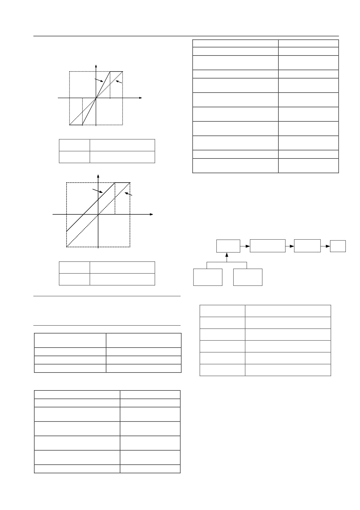
The curve of relation between analog output and gain and the
inflection point 1 given on curve 1
curve of relation between analog output and zero-bias correction
P11.32 Minimum given on curve 1
0.0%~P11.28【0.0%】
are respectively as shown in Fig.6-53 and Fig.6-54.
P11.33 Actual value corresponding to
0.0%~300.0%【0.0%】
The values aft:rV:
minimum given on curve 1
adjusted
10
P11.34 Maximum given on curve 2
P11.34~100.0%【100.0%】
P11.19=200
%
P11.19=100
P11.35 Actual value corresponding to
%
0.0%~300.0%【100.0%】
maximum given on curve 2
:
10
:
5
5
10
P11.36 Inflection point 2 given on curve
0
The values
P11.40~P11.36【100.0%】
before
: V:
2
adjusted
P11.37 Actual value corresponding to
0.0%~300.0%【100.0%】
inflection point 2 given on curve 2
:
10
P11.38 Inflection point 1 given on curve
P11.34~P11.38【0.0%】
Fig.6-53 Curve of Relation between Analog Output and Gain
2
P11.39 Actual value corresponding to
调整后的值
The values after adjusted
0.0%~300.0%【0.0%】
inflection point 1 given on curve 2
P11.40 Minimum given on curve 2
0.0%~P03. 11【0.0%】
调整前的值
The values before adjusted
P11.41 Actual value corresponding to
0.0%~300.0%【0.0%】
minimum given on curve 2
The values after adjusted
Analog input AI1~AI3 and pulse input can be given as different
10
P11.20=50
channels; for function selection of analog input channel, see the
%
P11.20=0
setting of function codes in the P11 group; for function selection
5
of pulse input, see the setting of input function of terminal X8. for
:
10
5
10
example, when AI1, AI2, AI3 or pulse frequency (PULSE) input is
0
The values
selected as frequency given channel, the relation between given
before adjust:d V:
frequency and set frequency is as shown in Fig.6-55 (AI1 is
selected as main frequency given channel).
Channel gain and zero
Selection of
Set
:
10
Channel filter
bias
frequenc
P11.04
P11.03: P1102
P11.25
y
Fig.6-54 Curve of Relation between Analog Output and Zero Bias
调整后的值
The values after adjusted
Selection of frequency
Selection of analog
given channel
input channel
调整前的值
The values before adjusted
P02.03
P11.01
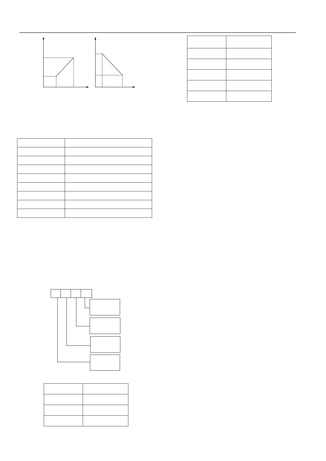
Fig.6-55 Relation between Given Channel Input and Set Frequency
Attention
Output gain and zero-bias correction function codes have a
通道滤波
Channel filter
real-time influence on analog output in the modification
process.
通道增益和零偏
Channel gain and zero bias
曲线 1 或 2 选择
Selection of curve 1 or 2
P11.21 AO2 terminal output
0~25【0】
function option
设定频率
Set frequency
P11.22 AO2 output filter
0.0~20.0s【0.1】
频率给定通道选择
Selection of frequency given channel
P11.23 AO2 output gain
0.0~200.0%【100.0%】
P11.24 AO2 zero-bias correction
-100.0~100.0%【0.0%】
模拟输入通道选择
Selection of analog input channel
Function setting of analog output of AO2 terminal and its meaning
are identical with AO1.
The relation between set frequency and given analog signal after
P11.25 Curve option
0000~1111【0000】
filter, gain and zero bias processing is determined by curve 1 or
P11.26 Maximum given on curve 1
P11.26~100.0%【100.0%】
curve 2. Curve 1 is defined by P11.26~P11.33 and curve 2 is
P11.27 Actual value corresponding to
0.0%~300.0%【100.0%】
defined by P11.34~P11.41. Take set frequency for example, both
maximum given on curve 1
P11.28 Inflection point 2 given on curve
can independently realize positive action characteristic and
P11.32~P11.28【100.0%】
1
reverse action characteristic, as shown in Fig. 6-56.
P11.29 Actual value corresponding to
Fig. 6-56 shows the correspondence relation of inflection point
0.0%~300.0%【100.0%】
inflection point 2 given on curve 1
setting on the curve determined by maximum and minimum given
P11.30 Inflection point 1 given on curve
P11.26~P11.30【0.0%】
points. If an inflection point is set additionally, the flexible
1
correspondence relation can be realized; for details, see the
P11.31 Actual value corresponding to
0.0%~300.0%【0.0%】
example analysis hereinafter.
81
Chapter VI Function Code Details
Set
Set
AI1 曲线选择
AI1 curve option
frequency
frequency
fmax
AI2 曲线选择
AI2 curve option
f
max
AI3 曲线选择
AI3 curve option
PULSE 曲线选择
PULSE curve option
f
f mi n
mi n
曲线 1
Curve 1
Pmi n
Pmax
P
Pmi n
Pmax
P
Ami n
Amax
A
Ami n
Amax
A
曲线 2
Curve 2
Positive action
Reverse action
(1)
characteristic
( 2)
characteristic
P: Terminal pulse given
Pm i n: Ami n: Minimum given
Pmax: Amax: Maximu m given
f mi n:C orresponding minimum
f max: Corresponding maximum
For example, demand analysis:
frequency given
frequency given
1. Use the pulse signal of terminal input to set the set frequency;
Fig.6-56 Characteristic Curve of Analog Output Frequency
2. Input signal 1kHz~20kHz;
设定频率
Set frequency
3.The corresponding set frequency of 1kHz input signal is 50Hz;
the corresponding set frequency of 8kHz input signal is 10Hz; the
正作用特性
Positive action characteristic
corresponding set frequency of 12kHz input signal is 40Hz; the
反作用特性
Reverse action characteristic
corresponding set frequency of 20kHz input signal is 5Hz.
端子 pulse 给定
Terminal pulse given
According to the above requirements, parameter setting is as
模拟量 AI1~AI3 给定
Analog AI1~AI3 given
below:
最小给定
Minimum given
1)P02.03=4, use terminal PULSE given as main frequency given
最大给定
Maximum given
channel;
2)P10.07=45, input pulse signal from terminal X8;
最小给定对应频率
Corresponding minimum frequency given
最大给定对应频率
Corresponding maximum frequency given
3)P11.25=1000, select curve 2;
4)P10.13=20.0kHz, set maximum pulse input frequency to be
20kHz;
When analog input A is 100%, it corresponds to 10V or 20mA;
5)P11.34=20÷20×100%=100.0%, set the maximum given on
when pulse frequency P is 100%, it corresponds to maximum
curve 2 as 20kHz-relative-to-20kHz (P10.13) percentage;
input pulse frequency defined by P10.13.
6 ) P11.35 = 5.00Hz÷P02.05*100 % , set the set frequency
For the channel filtering time constant defined by P11.04 and the
percentage corresponding to maximum given
(20kHz pulse
gain and zero bias defined by P11.03 and P11.02, refer to the
signal);
description of function codes in the P11 group.
7)P11.36=12÷20×100%=60.0%, set the inflection point 2
P11.25 is used for selection of analog input and pulse input curves,
given on curve
2 as
12kHz-relative-to-20kHz
(P10.13)
see Fig.6-57.
One
percentage;
Thousands
Tens
s
place Hundreds
place
place
plac
e
8 )P11.37 =40.00Hz÷P02.05*100 % , set the set frequency
AI1 curve option
percentage corresponding to inflection point 2 given on curve 2
0: Curve 1
1: Curve 2
(12kHz pulse signal);
9)P11.38=8÷20×100%=40.0%, set the inflection point 1 given
AI2 curve option
0: Curve 1
on curve 2 as 8kHz-relative-to-20kHz (P10.13) percentage;
1: Curve 2
10)P11.39=10.00Hz÷P02.05*100%, set the set frequency
AI3 curve option
percentage corresponding to inflection point 1 given on curve 2
0: Curve 1
1: Curve 2
(8kHz pulse signal);
PULSE curve option
11)P11.40=1÷20×100%=5.0%, set the minimum given on
0: Curve 1
1 : Curve 2
curve 2 as 1kHz-relative-to-20kHz (P10.13) percentage;
12)P11.41=50.00Hz÷P02.05*100%, set the set frequency
Fig.6-57 Selection of Frequency Given Curve
percentage corresponding to minimum given (1kHz pulse signal).
个位
Ones place
十位
Tens place
百位
Hundreds place
千位
Thousands place
82
Chapter VI Function Code Details
Output frequency%)
6.1.13 Encoder parameters (P12 group)
P11.41=100%
Local encoder function in the P12 group is used for vector control
P11.37=80
of asynchronous motor with PG.
%
P12.00 Pulses per revolution of
0~10000【1024】
local PG
P11.39=20
Pulse signal
%
It is set according to the pulses per revolution
(PPR) of the
P11.35=10
input
5%
40% 60%
100%
%
selected pulse encoder (PG).
P11.4
P11.3
P11.3
P11.3
0
8
6
4
Attention
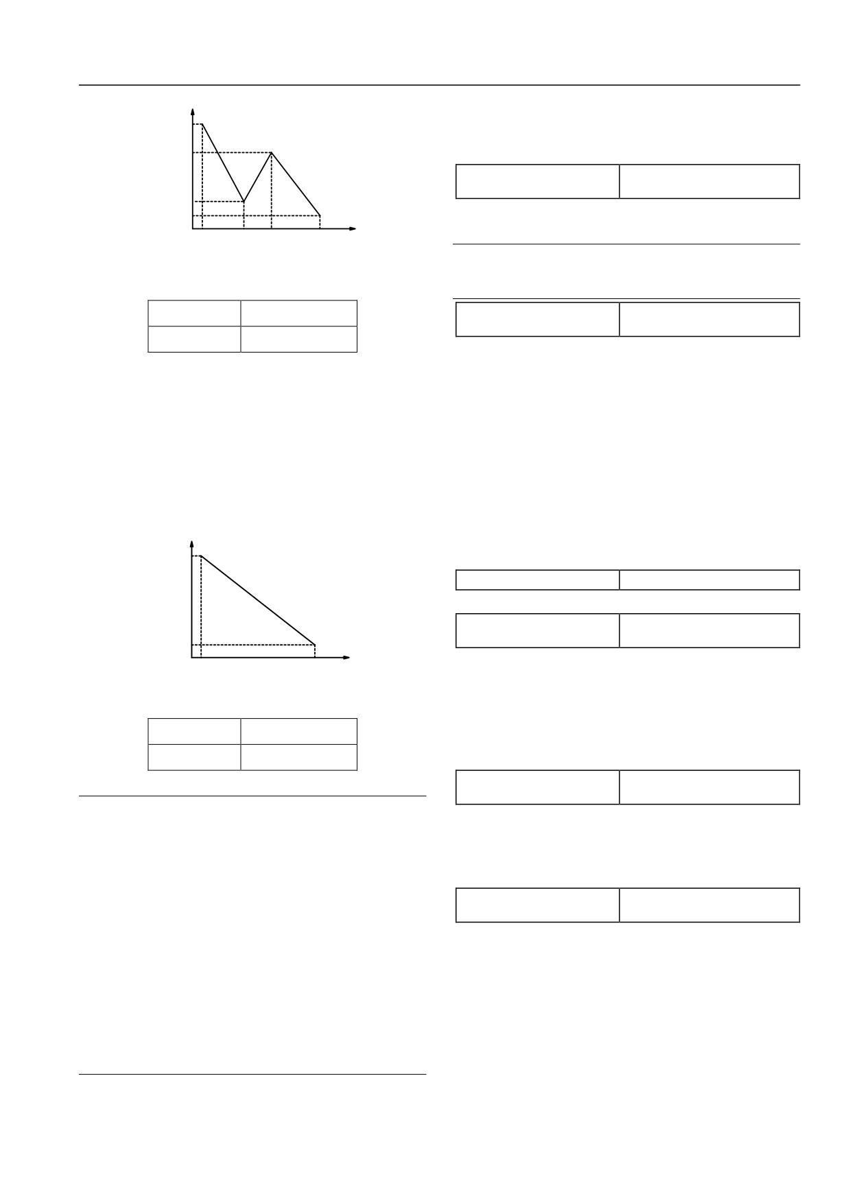
Fig.6-58 Pulse Signal Input Example-Parameter Setting 1
When a speed sensor is running, the parameter must be set
correctly, or else motor can not run normally.
输出频率
Output frequency
P12.01 Rotation direction of
0~1【0】
local PG
脉冲信号输入
Pulse signal input
0: A is in advance of B.
1: B is in advance of A.
If demand 3 has no setting of inflection point, the corresponding
When motor rotates forward, A is in advance of B; when motor
set frequency of
1kHz input signal should be
50Hz and the
rotates reversely, B is in advance of A. If the direction represented
corresponding set frequency of 20kHz input signal should be 5Hz.
by the sequence of connection between interface board of servo
For convenience, here inflection point 1 can be set as the same as
driver and PG matches with the direction represented by the
minimum given (P11.38=P11.40, P11.39=P11.41) and inflection
sequence of connection between servo driver and motor,
“0”
point 2 can be set as the same as maximum given (P11.36=
(forward) is selected as setting value, or else “1” (reverse) is
P11.34, P11.37=P11.35). The parameter curve is as shown in
selected.
Fig.6-59.
The correspondence relation of connection direction can be
adjusted easily by changing the parameter, and reconnection is not
Output frequency (%)
P11.41=100
%
needed.
P11.39
P12.02 Reserved
1~128【1】
The function code is Reserved.
P12.03 Filtering number of
0~99【30】
P11.35=10%
Pulse signal
encoder signal
P11.37
input
P11.34=100
It is used to set the filtering number of feedback speed.
P11.40=5%
%
P11.38
Ones place: high-speed filtering number
P11.36
Tens place: low-speed filtering number
Fig.6-59 Pulse Signal Input Example-Parameter Setting 2
At a low speed, if there is a current vibration sound, low-speed
输出频率
Output frequency
filtering number can be increased, or else it shall be decreased, to
脉冲信号输入
Pulse signal input
improve the response characteristic of the system.
P12.04 Disconnection
0~10s【0】
detectiontime of local PG
Attention
It means the detection duration for confirming the disconnection
1.If a user sets inflection point 2 given on curve 2 as the same
fault of coded disc.
as maximum given (P11.36=P11.34), it internally compels
P12.04=0 represents PG disconnection non-detection and E025
P11.37=P11.35, i.e. setting of inflection point 2 is invalid. If
fault can be masked.
inflection point 2 given is the same as inflection point 1 given
P12.05 Disconnection action of
(P11.38=P11.36), it internally compels P11.39=P11.37, i.e.
0~1【0】
local PG
setting of inflection point 1 is invalid. If inflection point 1
given is the same as minimum given (P11.40 = P11.38), it
0: free stop (E025)
internally compels P11.41=P11.39, i.e. setting of minimum
In the PG vector control mode and PG V/F control mode, if PG is
given is invalid. Setting of curve 1 is by analogy.
disconnected, servo driver will give a fault alarm and display
2. The range of actual value corresponding to curves 1 and 2
E025, and servo driver stops output simultaneously and motor
given is 0.0%~300.0%. For torque given, the corresponding
coasts to stop freely.
range is
0.0 % ~ 300.0 % ; for frequency given, the
1: Reserved
corresponding range is 0.0%~100.0% and setting of more
than 100.0% has the same meaning as 100.0%.
Detailed description of P12.06~P12.23 is Reserved.
83
Chapter VI Function Code Details
6.1.14 Process closed loop parameters (P13 group)
A pressure transmitter is used as feedback sensor of built-in closed
loop, to compose an analog feedback control system.
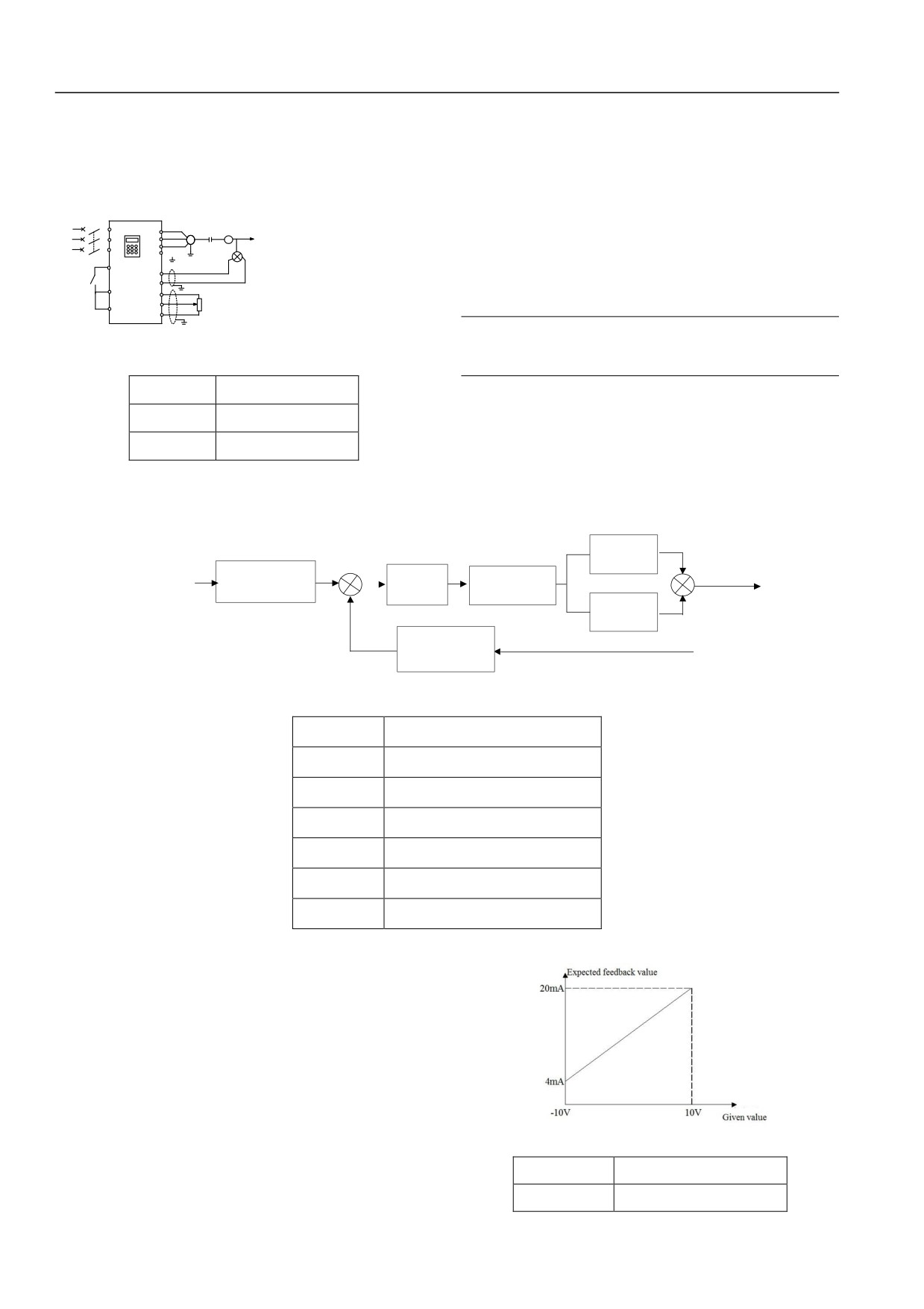
The process closed loop control system of HSD2000 servo driver
As shown in Fig.
6-60, given value of pressure is set by
is analog closed loop type. Fig. 6-60 is the connection diagram of
potentiometer and inputted from AI2 port in the form of voltage;
analog process closed loop control system of HSD2000 servo
feedback value of pressure is inputted from AI1 port in the form
driver.
of 4~20mA current; both given value and feedback value can be
QF
R
U
Delivery
AC
S
V
M
p
acquired by analog channel. Start and stop of closed loop
input
W
PE
T
Pressure
operation are realized by terminal FWD.
transmitter
FWD
P24
AI1 .
The above system can also be used for speed closed loop control
. COM
+10V .
of TG (tachogenerator).
GND
AI2
-10V
Attention
Fig.6-60 Analog Feedback Control System Diagram of Built-in Process
Given can also be digital given by operating panel and serial
Closed Loop
port given.
交流输入
AC input
The block diagram of working principle of HSD2000 built-in
process closed loop is given in Fig. 6-61; KP: proportional gain;
外送
Delivery
Ki: integral gain.
压力变送器
Pressure transmitter
In Fig.
6-61, the definitions of given value, feedback value,
deviation limit and proportional integral parameters of closed loop
Analog feedback control system:
are the same as ordinary closed loop regulation
meaning,
respectively see P13.01~P13.15 definitions.
KP ×
ε
Closed
Adjustment
(P13.10)
Given value
Deviation
+
loop
of given
+
Closed loop regulating
ε
output
of closed
(P13.06:
limit
characteristic
(P13.15)
(P13.16)
loop
P13.08)
-
∑
Ki × ε
+
(P13.11)
Adjustment of
Feedback
feedback value
value of
(P13.07: P13.09)
closed loop
Fig.6-61 Schematic Diagram of Process Closed Loop Control
闭环给定量
Given value of closed loop
给定量调整
Adjustment of given value
偏差极限
Deviation limit
闭环调节特性
Closed loop regulating characteristic
反馈量调整
Adjustment of feedback value
闭环输出
Closed loop output
闭环反馈量
Feedback value of closed loop
Built-in closed loop of HSD2000 has the two characteristics as
follows:
The relation between given value and corresponding expected
feedback value is defined by P13.06~P13.09.
For example, in Fig. 6-62, when given value is analog signal -
10~10V, the corresponding expected controlled value is 0~1MP
and the corresponding pressure sensor signal is 4~20mA; the
relation between given value and expected feedback value is as
shown in Fig. 6-62.
Fig.6-62 Given Value and Expected Feedback Value
期望的反馈量
Expected feedback value
给定量
Given value
84
Chapter VI Function Code Details
1: closed loop run control is valid.
Determination of given value is based on 10V; determination of
P13.01Given channel option
0, 1, 2, 3【1】
feedback value is based on 20mA
That is to say,
0: digital given
The meaning of adjustment of given value and feedback value in
Based on the value in P13.05
Fig. 6-61 is that given value and feedback value adopt internal
1: AI1 analog given
unified value.
2: AI2 analog given
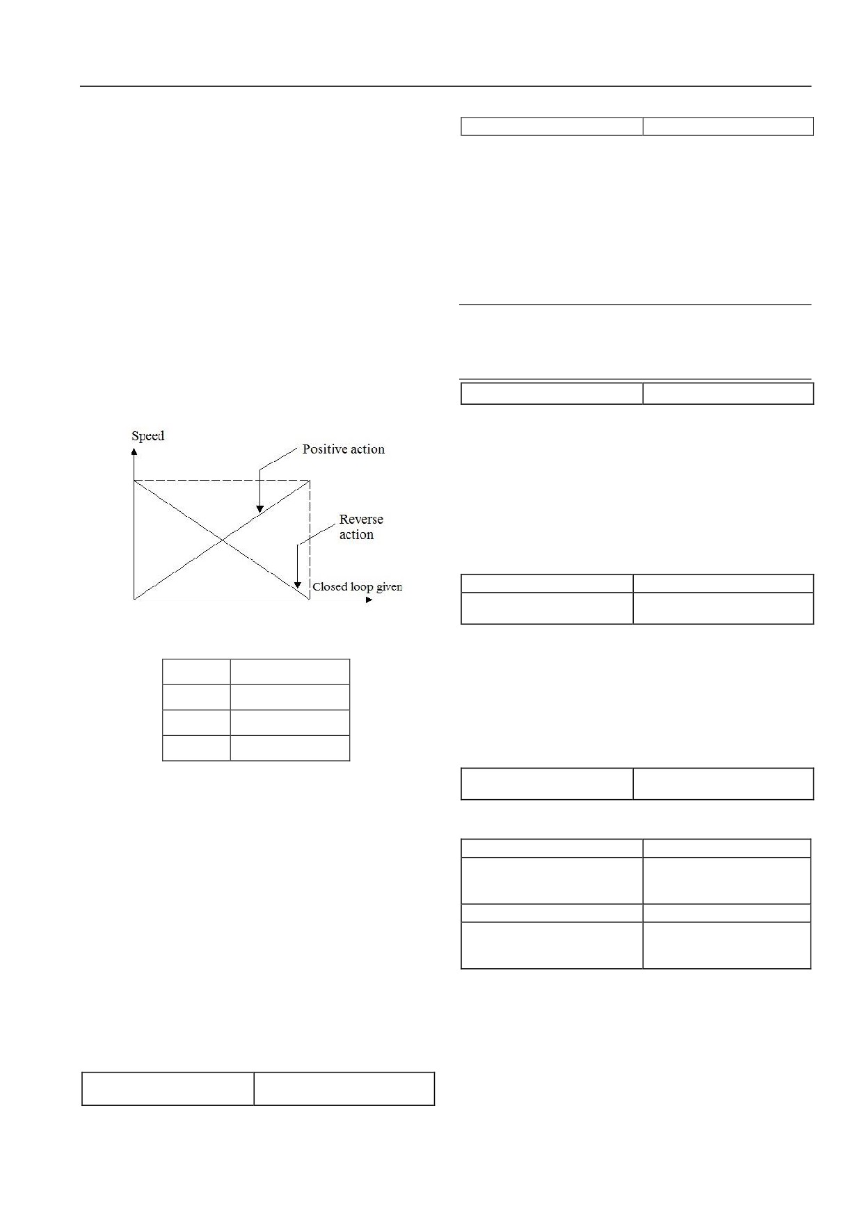
The closed loop characteristics are selected by P13.16, to satisfy
3: AI3 analog voltage given
different applications.
Analog given input -10~10V (P11.00 digit option 0), 4~20mA
In order to meet the control requirement in the actual control
(P11.00 digit option 1).
system, when given value increases, motor speed needs to be
increased, and such closed loop characteristic is positive action
Attention
characteristic; on the contrary, when given value increases, motor
Input of analog given AI1 and AI2 can be current or voltage
speed needs to be decreased, and such closed loop characteristic is
input by the function code P11.00
(digit option); AI3 as
reverse position characteristic.
differential input can only be voltage input.
As shown in Fig. 6-63, definition of P13.16 is for meeting the
P13.02 Feedback channel option
0~5【1】
requirements of two closed loop characteristics.
0: AI1 analog given
1: AI2 analog given
2:AI1+ AI2
3:AI1-AI2
4:Min{ AI1,AI2}
5:Max{ AI1,AI2}
AI input type option is the same as above.
P13.03 Given channel filtering
0.01~50.00s【0.50s】
P13.04 Feedback channel
0.01~50.00s【0.50s】
filtering
Fig. 6-63 Closed Loop Regulating Characteristic Diagram
External given signals and feedback signals often have a certain
转速
Speed
interference superposition and channels are filtered by setting the
filtering time constant in P13.03 and P13.04; the longer the
正作用
Positive action
filtering time is, the higher the interference resistance, but the
反作用
Reverse action
response becomes slow; the shorter the filtering time is, the
quicker the response is, but the interference resistance becomes
闭环给定
Closed loop given
weak.
P13.05 Digital setting of given
-10.00~10.00V【0.00】
After determination of the system, basic steps of closed loop
value
parameter setting are as below:
The function is used for digital setting of given value by operating
1)Determine the closed loop given and feedback channel
panel or serial port.
(P13.01、P13.02);
P13.06 Minimum given value
0.0%~P13.08【0.0%】
P13.07 Feedback value
2)For analog closed loop, set the relation between closed loop
corresponding to minimum given
0.0~100.0%【0.0%】
given and feedback (P13.06~P13.09);
value
P13.08 Maximum given value
P13.06~100.0%【100.0%】
3)Determine the closed loop regulating characteristic; if the
P13.09 Feedback value
relation between given and required motor speed is reverse, set the
corresponding to maximum given
0.0~100.0%【100.0%】
closed loop characteristic regulation as reverse action (P13.16=
value
1);
4)Set the integral regulation option and closed loop preset
The relation of given value adjustment in P13.06 and P13.08 in
frequency function (P13.17~P13.19);
Fig. 6-61 is as shown in Fig. 6-64. When analog input is 6V, if
P13.06=0% and P13.08=100%, the converted value after
5)Adjust the closed loop filtering time, sampling period, deviation
adjustment is
60%; if P13.06=25% and P13.08=100%, the
limit and gain coefficient (P13.10~P13.15).
converted value after adjustment is 46.6%.
P13.00 Closed loop run control
0, 1【0】
option
0: closed loop run control is invalid.
85
Chapter VI Function Code Details
The values after
Output filtering time is the filtering time of closed loop output
adjusted
(frequency or torque). The greater the output filtering time is, the
100%
slower the output response is.
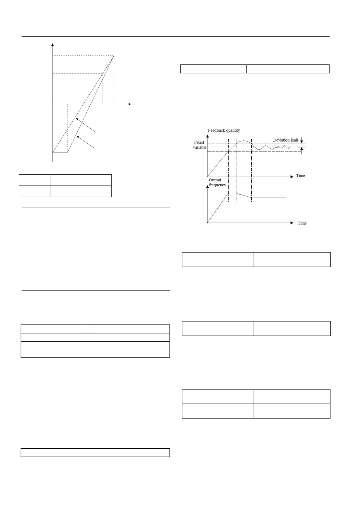
P13.15 Deviation limit
0.0~20%【2.0%】
60%
46.6%
System output value is relative to maximum deviation permitted
by given value of closed loop; as shown in Fig. 6-65, when
25%
50%
feedback value is within the range, closed loop regulator will stop
80%
Analog
0%
100%
regulation. Appropriate setting of the function is helpful to give
(6V)
input value
consideration to both accuracy and stability of system output.
P13.06=0%
P13.08=100%
P13.06=25%
-100%
P13.08=100%
Fig.6-64 Given Value Adjustment Curve Diagram
调整后的量
The values after adjusted
模拟输入量
Analog input value
Attention
1. As shown in Fig. 6-64, scaling analog input of horizontal
axis
0 % ~ 100 % is - 10V ~ 10V; analog input
10V
corresponds to 100% and -10V corresponds to 0%, and 6V
Fig.6-65 Deviation Limit Diagram
corresponds to 80%.
2. If it is analog current input, the range of current input is
P13.16 Closed loop regulating
0, 1【0】
4~20mA, so the range of scaling on the horizontal axis is
characteristic
50%~100%.
0: positive action
3. The values after adjusted can be observed by the function
When given value increases, it is used if requiring increasing
code P01.28.
motor speed.
As shown in Fig. 6-61, the relation curve of feedback value
1: reverse action
adjustment in P13.07 and P13.09 is relative to the adjustment of
When given value increases, it is used if requiring decreasing
given value. The values after adjusted can be observed by the
motor speed.
function code P01.29.
P13.17 Integral regulation
P13.10 Proportional gain KP
0.000~10.000【2.000】
0, 1【0】
option
P13.11 Integral gain Ki
0.000~10.000【0.100】
0: when the frequency reaches the upper and lower limits, stop
P13.12
Reserved
integral regulation;
P13.13 Sampling period T
0.01~50.00s【0.50s】
1: when the frequency reaches the upper and lower limits,
The greater the proportional gain KP is, the quicker the response
continue integral regulation.
is, but if KP is excessively great, it may cause oscillation easily.
For the system that requires quick response, it is suggested that
The deviation can not be eliminated completely only by
continuing integral regulation should be cancelled.
proportional gain KP adjustment. In order to eliminate residual
P13.18 Closed loop preset
deviation, integral gain Ki can be adopted to compose the closed
0.00~1000.0Hz【0.00Hz】
frequency
loop control. The greater the Ki is, the quicker the response to
P13.19 Holding time of closed
varying deviation is, but if Ki is excessively great, it may cause
0.0~3600.0s【0.0s】
loop preset frequency
oscillation easily.
Sampling period T is the sampling period of feedback value and
The function code can make closed loop regulation quickly enter
the closed loop regulator operates once within a sampling period.
into steady stage.
The greater the sampling period is, the slower the response is.
After closed loop run starts, the frequency first increases to the
P13.14 Output filtering time
0.01~10.00【0.05】
closed loop preset frequency P13.18 according to the acceleration
time, then it runs for a period of time P13.19 on the frequency
point, and finally runs according to the closed loop characteristic.
86
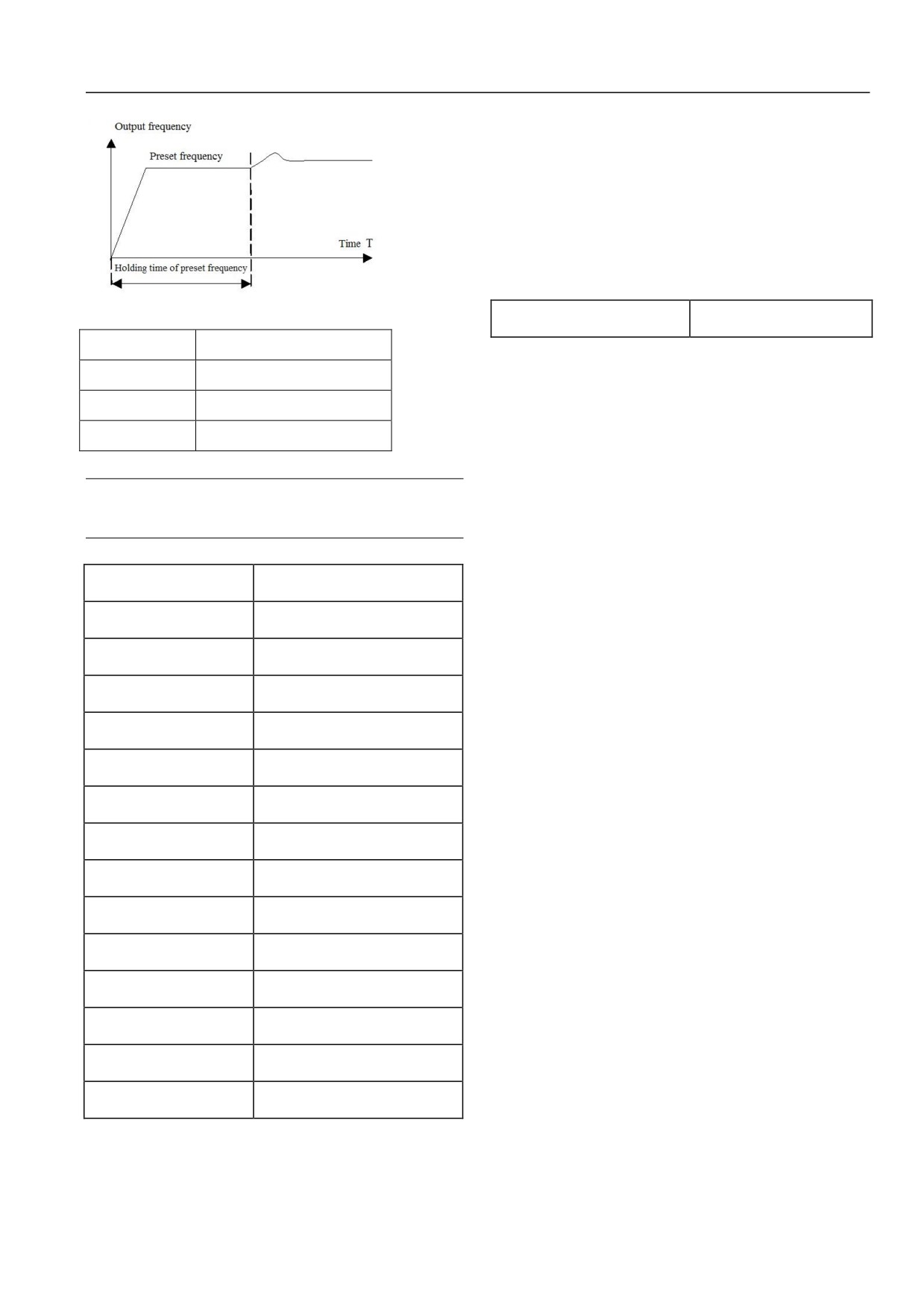
Chapter VI Function Code Details
closed loop given defined by P13.20~P13.34 can also be used as
closed loop given.
Voltage options of multi-phase closed loop given 1~15 can be
switched flexibly by external terminals, see P10.00 ~ P10.07
terminal functions 30~33. it can also be used in conjunction with
simple PLC closed loop section, see the description of function
codes in the P11 group.
The priority level of multi-phase closed loop given control is
higher than the given channel defined in P13.01.
P13.35 Closed loop output
Fig.6-66 Run Diagram of Closed Loop Preset Frequency
0, 1【0】
reversion option
输出频率
Output frequency
0: closed loop output is negative and servo driver runs at zero
预置频率
Preset frequency
frequency.
1: closed loop output is negative and servo driver runs reversely,
预置频率保持时间
Holding time of preset frequency
but if anti-reversion option disables reverse running, servo driver
时间
Time
runs at zero frequency, see the description of P05.12 function code.
Attention
If the closed loop preset frequency function is not needed,
preset frequency and holding time should be set as 0.
P13.20 Multi-phase closed
-10.00~10.00V【0.00V】
loop given 1
P13.21 Multi-phase closed
-10.00~10.00V【0.00V】
loop given 2
P13.22 Multi-phase closed
-10.00~10.00V【0.00V】
loop given 3
P13.23 Multi-phase closed
-10.00~10.00V【0.00V】
loop given 4
P13.24 Multi-phase closed
-10.00~10.00V【0.00V】
loop given 5
P13.25 Multi-phase closed
-10.00~10.00V【0.00V】
loop given 6
P13.26 Multi-phase closed
-10.00~10.00V【0.00V】
loop given 7
P13.27 Multi-phase closed
-10.00~10.00V【0.00V】
loop given 8
P13.28 Multi-phase closed
-10.00~10.00V【0.00V】
loop given 9
P13.29 Multi-phase closed
-10.00~10.00V【0.00V】
loop given 10
P13.30 Multi-phase closed
-10.00~10.00V【0.00V】
loop given 11
P13.31 Multi-phase closed
-10.00~10.00V【0.00V】
loop given 12
P13.32 Multi-phase closed
-10.00~10.00V【0.00V】
loop given 13
P13.33 Multi-phase closed
-10.00~10.00V【0.00V】
loop given 14
P13.34 Multi-phase closed
-10.00~10.00V【0.00V】
loop given 15
Among the closed loop given channels except the three kinds of
channels defined by P13.01, the voltage value of multi-phase
87
Chapter VI Function Code Details
P13.36 Closed loop feedback loss
0, 1, 2【0】
1.5kW~15kW
15.0
2.0
8.0
action option
18.5kW~45kW
10.0
2.0
4.0
0: closed loop feedback loss detection is not available;
55kW~75kW
6.0
2.0
3.0
1: closed loop feedback loss detection is available; when
detected, continue running and display the alarm A021;
Above 90kW
3.0
2.0
2.0
2: closed loop feedback loss detection is available; when
detected, stop freely and display the fault E021;
When displaying an alarm to continue running, running frequency
Attention
is described as P20.04 function code.
1. Carrier frequency will affect the running noise of motor
P13.37 Detection value of closed
and it is usually set at 3~5kHz. In the place requiring silent
0.0~100.0%【50.0%】
loop feedback loss
running, carrier frequency is usually set at 6~8kHz.
P13.38 Detection time of closed
0.0~20.0s【1.0s】
2. When running at above factory set carrier frequencies,
loop feedback loss
servo driver should be derated by 5% for use with an increase
Detection value of closed loop feedback loss is
100 % as
of 1kHz.
reference value; within the detection time, if closed loop feedback
3. In the vector control mode, P14.00 minimum
carrier
value is lower than detection value, servo driver will operate
frequency is 3kHz.
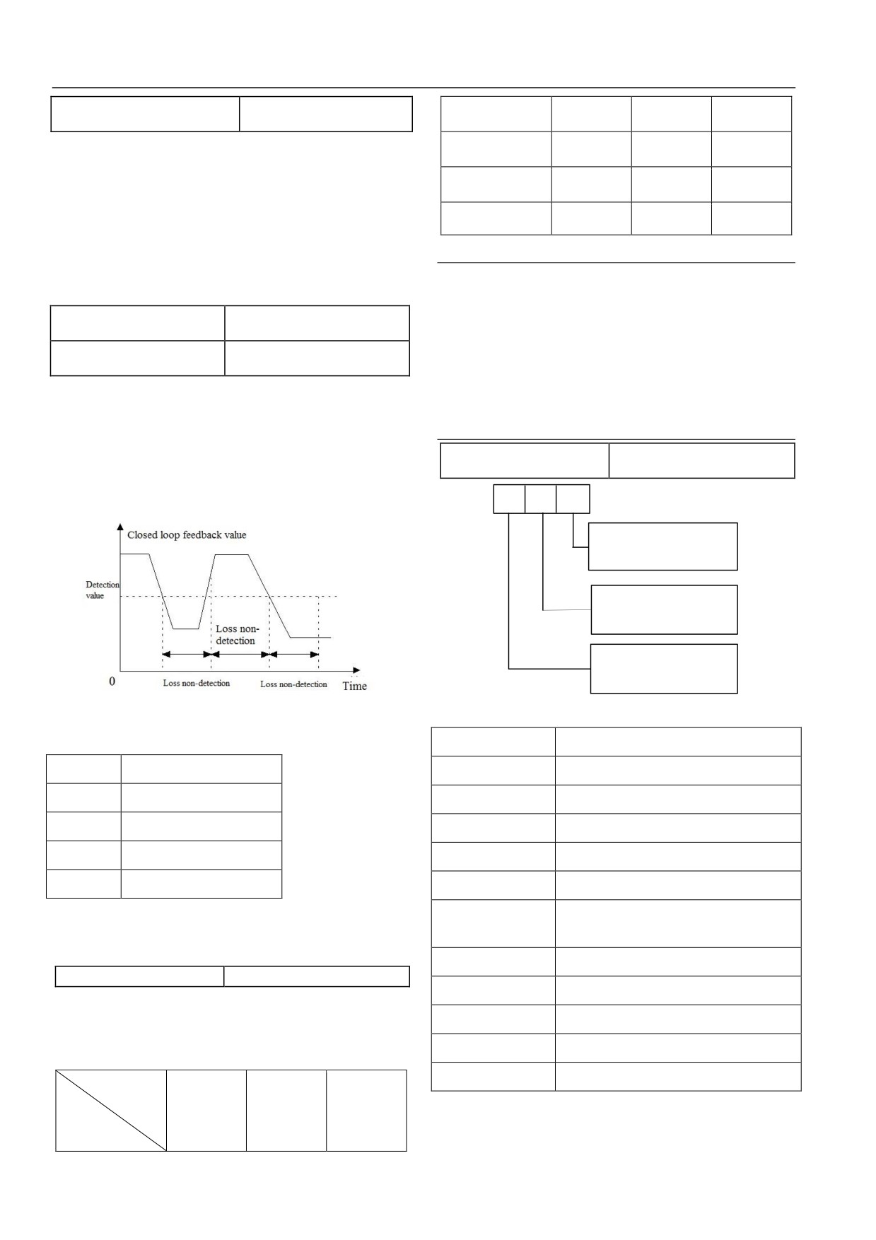
according to setting of P13.36 function code. The time sequence
P14.01 PWM mode
000~111【001】
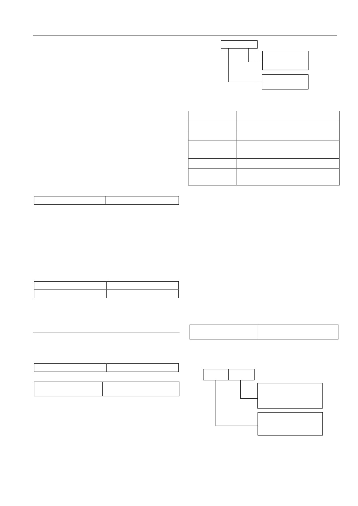
diagram of closed loop feedback loss detection is as shown in Fig.
optimization
One
6-67.
HundredsTens
s
place
place
plac
e
PWM overmodulation
enable
0: Invalid
1: Valid
Automatic adjustment option of
PWMNon-ier frequency
automatic
0:
Aadjustment
1:
adjustment
PWM adjustment mode
0T
wo-phase/three-phase switching
Three-phase
1:
modulation
Fig.6-68 PWM Mode Optimization Option
Fig.6-67 Time Sequence Diagram of Closed Loop Feedback Loss
Detection
百位
Hundreds place
闭环反馈值
Closed loop feedback value
十位
Tens place
检出值
Detection value
个位
Ones place
丢失不检出
Loss non-detection
PWM 过调制使能
PWM overmodulation enable
丢失检出
Loss detection
无效
Invalid
时间
Time
有效
Valid
PWM 载波频率自动
Automatic adjustment option of PWM carrier
调整选择
frequency
6.1.15 Extended function code parameters (P14 group)
不自动调整
Non- automatic adjustment
P14.00 Carrier frequency
2.0~15.0kHz【8kHz】
自动调整
Automatic adjustment
PWM 调整方式
PWM adjustment mode
Table 6-15 Carrier Frequency of PWM Wave Outputted by Servo
Driver
两相/三相切换
Two-phase/three-phase switching
三相调制
Three-phase modulation
Maximum
Minimum
Carrier frequency
Factory
carrier
carrier
setting
frequency
frequency
Model
(kHz)
Ones place: overmodulation enable
(kHz)
(kHz)
88
Chapter VI Function Code Details
The function decides whether to enable V/F control
Tens place Ones place
overmodulation function. Vector control overmodulation is
0:Set frequency storage in
enabled all the time.
case of power down
1:Set frequency non-storage
0: invalid
in case of power down
V/F control overmodulation function is disabled.
0 :Frequency holding in case of
stop
:
Frequency recovery P02.04 in
1: valid
case of stop
V/F control overmodulation function is enabled.
Fig.6-69 LED Setting of Digital Frequency Control
Tens pace: automatic adjustment option of carrier frequency
0: non-operating
个位
Ones place
1: operating
十位
Tens place
When automatic adjustment option of carrier frequency is
设定频率掉电存储
Set frequency storage in case of power down
“operating”, servo driver can automatically adjust the carrier
设定频率掉电不存
Set frequency non-storage in case of power down
frequency according to internal temperature. Here actual
储
maximum run frequency of servo driver is restricted by the carrier
frequency set by function code (P14.00).
停机频率保持
Frequency holding in case of stop
Hundreds place: modulation mode
停 机 频 率 恢 复
Frequency recovery P02.04 in case of stop
0: two-phase/three-phase switching
P02.04
1: three-phase modulation
P14.02 cooling fan control
0~1【1】
Ones place:
0: set frequency storage in case of power down
0: automatic run
When servo driver is power-down or under-voltage, P02.04 is
Servo driver automatically starts internal temperature detection
refreshed automatically according to the set value of current actual
program when it is running, to determine running and stop of fan
frequency.
according to the module temperature. Before servo driver stops, if
the fan is running, the fan will continue running 3min when servo
1: set frequency non-storage in case of power down
driver stops, and then internal temperature detection program is
When servo driver is power-down or under-voltage, P02.04
started.
remains unchanged.
1: power-on fan is always running
Tens place:
After servo driver is electrified, the fan is always running.
0: set frequency holding in case of stop
P14.03 ACR-P
1~5000【1000】
When servo driver stops, set value of frequency is final modified
P14.04 ACR-I
0.5~100.0ms【8.0ms】
value.
P14.03 and P14.04 are PI regulator parameters of electric current
1: set frequency recovery P02.04 in case of stop
loop. Increasing electric current loop KP or reducing I can
When servo driver stops, set value of frequency is automatically
accelerate dynamic response of system torque; reducing KP or
restored to P02.04.
increasing I can strengthen the stability of the system.
P14.07 Auxiliary set frequency
00~11【00】
control
Attention
For most purposes, it is needless to adjust PI parameters of
electric current loop, so it is suggested that users should not
P14.07: digital auxiliary frequency control is valid only when
change this group of parameters at will.
P02.08=1~3, as shown in Fig. 6-70.
P14.05 Reserved
0~65535【0】
Tens placeOnes place
P14.06 Main set frequency
00~11【00】
0:Auxiliary frequency storage in
control
case of power down
1:Auxiliary frequency non-
storage in case of power down
It is valid only in case of P02.00=0, 1, 2.
0:Auxiliary frequency holding
after stop
1:Auxiliary frequency clearing
after stop
Fig.6-70 Setting of Digital Auxiliary Frequency Control
89
Chapter VI Function Code Details
Ones place
Tens place
Auxiliary frequency storage in case of power down
Auxiliary frequency non-storage in case of power
down
Auxiliary frequency holding after stop
Auxiliary frequency clearing after stop
Ones place: power-down storage option
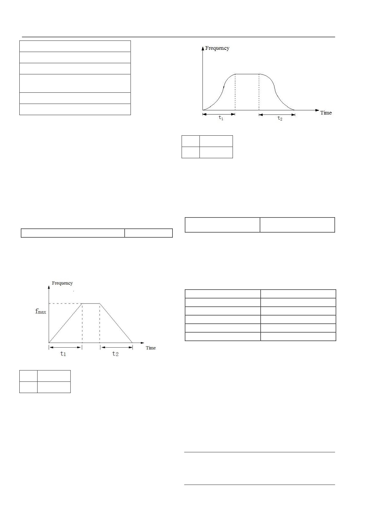
Fig.6-72 S-Curve Acceleration/Deceleration
0: auxiliary frequency storage in case of power down
频率
Frequency
Auxiliary frequency will be stored in the P02.10 in case of power
时间
Time
down
1: auxiliary frequency non-storage in case of power down
When acceleration starts and speed arrives and when deceleration
Auxiliary frequency will not be stored in case of power down.
starts and speed arrives, make the set value of speed in S-curve
Tens pace: frequency processing after stop
state. This way can make acceleration/ deceleration act smoothly
0: auxiliary frequency holding after stop
and have little impact. S-curve acceleration/ deceleration mode is
Auxiliary frequency remains unchanged after stop.
suitable for start and stop of load handling and transfer, e.g.
1: auxiliary frequency clearing after stop
elevators and conveyor belts, etc.
P14.09 Acceleration/ deceleration
Auxiliary frequency is cleared after stop
0~2【1】
time unit option
P14.08 Acceleration/deceleration mode option
0~1【0】
0:0.1s
0: linear acceleration/deceleration
1:s
Output frequency increases or decreases by degrees according to a
2:min
constant gradient, as shown in Fig.6-71.
The function is used to determine all acceleration/ deceleration
time units except jog run.
P14.10 Acceleration time 2
0.0~3600.0s (min)【6.0s】
P14.11 Deceleration time 2
0.0~3600.0s (min)【6.0s】
P14.12 Acceleration time 3
0.0~3600.0s (min)【6.0s】
P14.13 Deceleration time 3
0.0~3600.0s (min)【6.0s】
P14.14 Acceleration time 4
0.0~3600.0s (min)【6.0s】
P14.15 Deceleration time 4
0.0~3600.0s (min)【6.0s】
Acceleration time refers to the required time (t1 in Fig.6-71) of
servo driver accelerating to maximum output frequency (P02.05)
from zero frequency. Deceleration time refers to the required time
Fig.6-71 Linear Acceleration/ Deceleration
(t2 in Fig.6-71) of servo driver decelerating to zero frequency from
频率
Frequency
maximum output frequency (P02.05.)
时间
Time
Total four kinds of acceleration/ deceleration time are defined for
HSD2000 servo drivers and acceleration/ deceleration time 1~4
in the running process of servo driver can be selected by different
1: S-curve acceleration/deceleration
combination of control terminals, see the definition of
Output frequency increases or decreases by degrees according to
acceleration/deceleration time terminal function in the P10.00~
an S-curve, as shown in Fig.6-72.
P10.07. They can also be defined as the acceleration/deceleration
time when running frequency in each phase switches in the simple
PLC run mode, see the description of P15 parameter group.
Attention
1. Second and minute can be selected as the unit of
acceleration/ deceleration time 1~4 by P14.09 and factory
default unit is second.
90
Chapter VI Function Code Details
2. Factory set value of acceleration/deceleration time of 1.5~
P14.21
22kW servo drivers is
6.0s; factory set value of
acceleration/deceleration time of 30~45kW servo drivers is
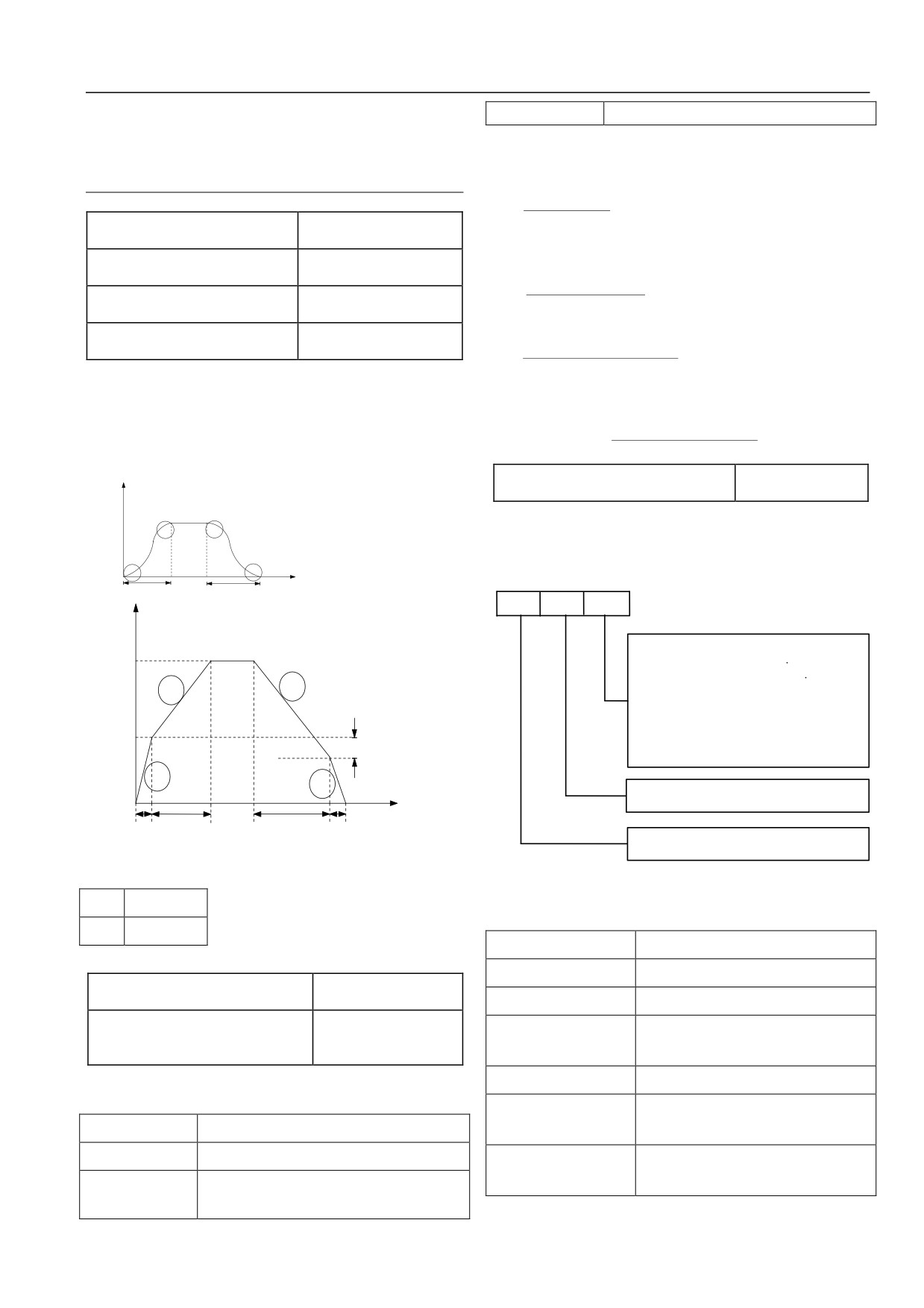
As shown in Fig. 6-74, at the time of acceleration, it first runs by
20.0s; factory set value of acceleration/deceleration time of
other servo drivers is 30.0s.
acceleration time 1, as shown in curve ①, and acceleration time
P1420
P
2
. When output frequency increases to the
t
1
P14.16 Time in the S-curve
P
2
10.0%~50.0%【20.0%】
acceleration start section
switching point P14.20, acceleration time will switch to P14.10
P14.17 Time in the S-curve
10.0%~80.0%【20.0%】
from P02.14, as shown in curve
②, and acceleration time
acceleration end section
(fP
142)
0
P
4
P14.18 Time in the S-curve
t
. At the time of deceleration, it first
2
10.0%~50.0%【20.0%】
P
2
deceleration start section
runs by deceleration time
2, as shown in curve
③ , and
P14.19 Time in the S-curve
10.0%~80.0%【20.0%】
deceleration end section
(fP
1.4P1.4)P
.4
t
When output frequency
3
P
.2
decreases to a frequency (P14.20-P14.21) lower than P14.20,
P14.16
~ P14.19 are valid only when S-curve
deceleration time 2 will switch to deceleration time 1, as shown in
acceleration/deceleration mode
(P04.00 = 1) is selected, and
P1.4 P1.4)P
.2
P14.16+P14.1790 % , P14.18+P14.1990 % , as shown in
curve ④, and
t
4
P
.2
Fig.6-73 below.
P14.22 Binding of run command channels
Frequency
000~666【000】
and frequency given channels
P14.17
P14.18
The function defines the binding combination of three kinds of
run command channels and six kinds of frequency given channels,
P14.19
P14.16
Time
to realize synchronous switching easily.
t1
t2
Hundreds
Tens placenes place
Frequency
place
Frequency channel option in the operating panel
control mode
f
0 : No binding
1 : Digital setting 1 (adjusted by : and : on the operating panel
3
2
2 : Digital setting 2 (adjusted by terminal UP/DN)
3 :
Digital setting 2 (given by serial port)
4 : AI a nalog given
P14.2
Switching hysteresis loop
5 : Terminal pulse
given
0
frequency P14.21 of
acceleration/deceleration time
6 : Extend
ed card given
1 and 2
1
4
Frequency channel option in the terminal control mode
0: 6 : S ame as above
Time
t1
t2
t3
t4
Frequency channel option in the serial port control mode
0:
6 :
Same as above
Fig.6-73 Acceleration/Deceleration Start and End Time
Fig.6-75 Binding of Run Command Channels and
频率
Frequency
Frequency Given Channels
时间
Time
个位
Ones place
十位
Tens place
P14.20 Switching frequency of
0.00~1000.0Hz【0.00】
acceleration/deceleration time 1 and 2
百位
Hundreds place
P14.21 Switching hysteresis loop
操作面板控制方式下
Frequency channel option in the
frequency of acceleration/deceleration
0.00~655.35Hz【1.00】
operating panel control mode
time 1 and 2
频率通道选择
无捆绑
No binding
Fig.6-74 Switching Diagram of Acceleration/Deceleration Time 1 and 2
数字设定 1(操作面板
Digital setting 1 (adjusted by ▲ and ▼
频率
Frequency
on the operating panel)
▲、▼调节)
时间
Time
数字设定 2(端子
Digital setting 2 (adjusted by terminal
UP/DN 调节)
UP/DN)
加减速时间 1 和
Switching hysteresis loop frequency P14.21
of acceleration/deceleration time 1 and 2
2 切换滞环频率
91
Chapter VI Function Code Details
数字设定 3(串行口给
Digital setting 2 (given by serial port)
端子控制方式
Terminal control mode
定)
AI 模拟设定方式
AI analog setting mode
AI 模拟给定
AI analog given
本地
Local
端子脉冲给定
Terminal pulse given
操作面板控制方式
Operating panel control mode
扩展卡给定
Expansion card given
数字设定方式 1
Digital setting mode 1
端子控制方式下频率
Frequency channel option in the
多功能输入端子 Xi
Multi-function input terminal Xi
通道选择
terminal control mode
上电
Power on
串行口控制方式下频
Frequency channel option in the serial
port control mode
率通道选择
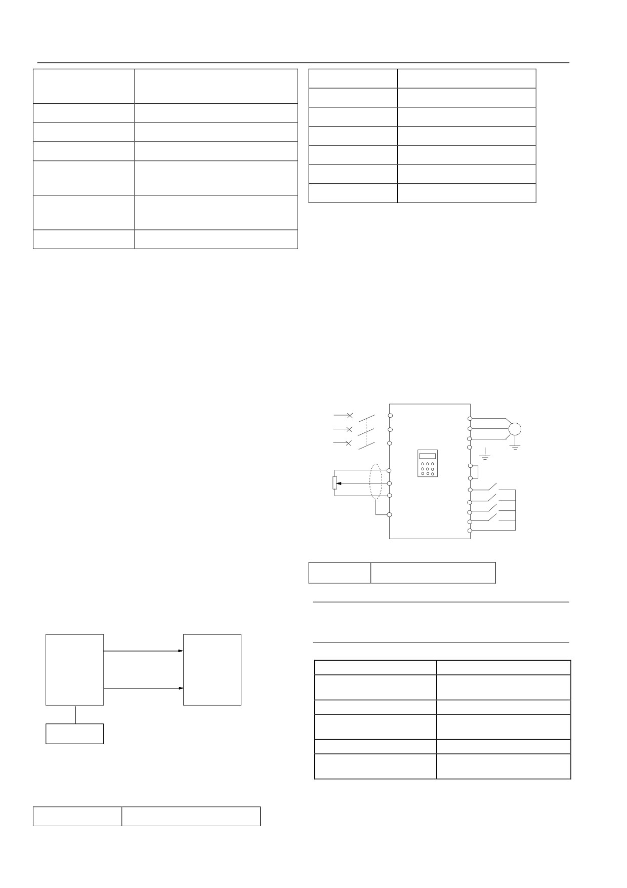
In order to realize the above control, the following setting is
同上
Same as above
required.
The meaning of the above frequency given channels is the same as
P02.02=1, set as terminal control mode; it is remote control after
frequency setting mode P02.03, see the description of function
power on;
codes in the P02 group.
P10.00=28, P10.01=29, set multi-function input terminals X1
Different run command channels can be bound to the same
and X2 as run command channel option;
frequency given channel.
P10.08=1, set as two-wire control mode 2; when FWD is valid, it
Online synchronous switching after binding can be realized by the
runs forward; when REV is valid, it runs reversely;
following modes:
P00.06=0020, set LOCAL key to be valid;
Mode 1: modify the function code “run command channel option
P14.22=041, set terminal control mode is bound to AI analog
P02.02”;
given and operating panel control mode is bound to digital setting
Mode 2: use LOCAL and DATA/ENTER keys;
1.
Mode 3: use the combination of run command channel option
Three-
QF
R
terminals (terminal function should be defined and X1~X8 are
U
phase
AC
S
V
set as 28 and 29).
HSD2000
M
power
W
T
For example,
supply
PE
In order to facilitate remote and local control, requirements are as
P24
+10 V
follows:
PLC
4.7k
AI
K1
①Switching of run command channel: switch by terminal in
FWD
-10V
K2
remote control mode and switch by LOCAL key in local control
REV .
K3
PE
X1
mode.
K4
C X2 .
②Local control adopts operating panel; press RUN key to run and
press STOP key to stop; set frequency is adjusted by ▼ and ▲.
Fig.6-77 Connection Diagram of Remote and Local Control Hardware
③Remote control adopts external terminal; close FWD key to run
三相交流电源
Three-phase AC power supply
forward and close REV key to run reversely; set frequency is
adjusted by AI analog given.
④After power on, terminal control mode is available.
Attention
Factory setting is 000: no synchronous switching of frequency
Remote
Local
given channel
Terminal
Multi-function input
Operating panel
control mode
terminal Xi
control mode
P14.23 Jump frequency 1
0.00~1000.0Hz【0.00Hz】
P14.24 Range of jump
AI analog
P ANEL/REM OT E
Digital setting
0.00~30.00Hz【0.00Hz】
ENTER/DA TA
frequency 1
setting mode
mode 1
P14.25 Jump frequency 2
0.00~1000.0Hz【0.00Hz】
P14.26 Range of jump
0.00~30.00Hz【0.00Hz】
Power on
frequency 2
P14.27 Jump frequency 3
0.00~1000.0Hz【0.00Hz】
P14.28 Range of jump
0.00~30.00Hz【0.00Hz】
frequency 3
P14.23 ~ P14.28 are set for the purpose of making output
Fig.6-76 Remote and Local Control Requirement
frequency of servo driver avoid the resonance frequency points of
远程
Remote
mechanical load.
92
Chapter VI Function Code Details
Set frequency of servo driver can jump nearby some frequency
points according to the mode in Fig.6-78 and at most three jump
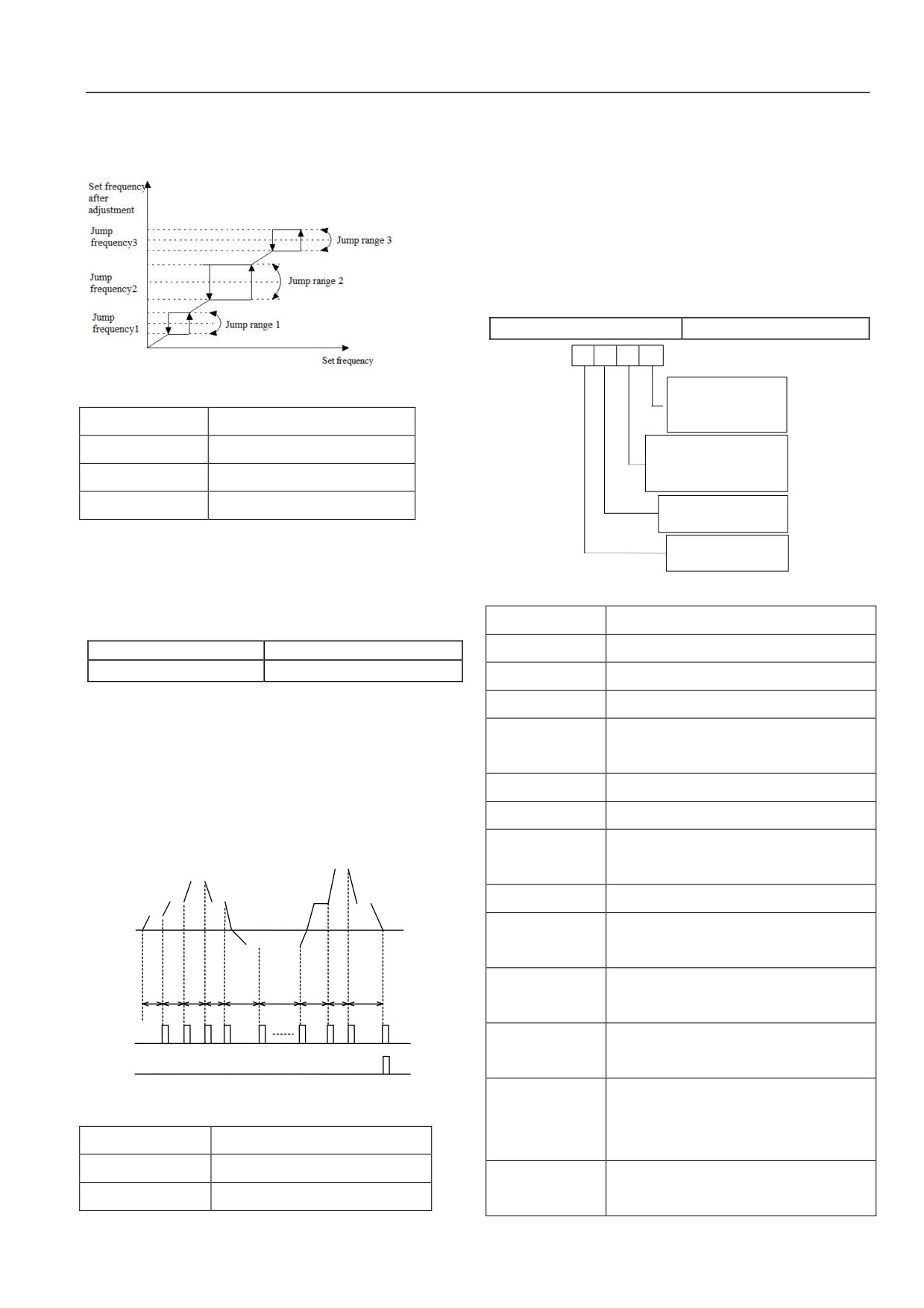
In the Fig.6-79, a1 ~ a15 and d1 ~ d15 are acceleration and
ranges can be defined.
deceleration time in each phase; P1~P15 and T1~T15 are set
frequency and running time in each phase. The above parameters
will be defined respectively in the following function codes.
PLC phase and cycle completion can be indicated by two-way
open collector output terminals Y1 and Y2 or relay outputting
500ms pulse indication signals, see the function 11 “PLC phase
run completion indication” and function
12
“PLC
cycle
completion indication” in the P10.18~P10.21.
P15.00 PLC run mode option
0000~1123H【0000】
ThousanHundred
Tens
Ones
s place
s place
place
place
Fig.6-78 Jump Frequency and Range Diagram
PLC run mode option
0: Non-operating
1:Stop after single cycle
Set frequency after adjustment
2: Keep final value after single
调节后的设定频率
cycle
3:Continuous cycle
Restart mode after PLC run
跳跃频率
Jump frequency
interruption
0 :Rerun from the first phase
1Continue running from the phase at the
跳跃范围
Jump range
interruption moment
Continue running from the phase
2:
and frequency at the interruption
moment
设定频率
Set frequency
PLC state parameter storage option
in case of power down
0 : Not stored
1: Store the phase and frequency at the
After the jump frequency parameter is set, even if set frequency of
power-down moment of
Phase time unit option
servo driver is in the mechanical resonance frequency zone of
0: Second
1: Minute
drive system, output frequency of servo driver will also be
Fig.6-80 Selection of Simple PLC Run Mode
adjusted out of mechanical resonance zone, to avoid running on
个位
Ones place
the resonance frequency.
十位
Tens place
P14.29 Reserved
P14.30 Reserved
50~150【100】
百位
Hundreds place
千位
Thousands place
6.1.16 Simple PLC parameters (P15 group)
PLC 运行方式选
PLC run mode option
Simple PLC function is a multi-speed generator. Servo driver can
择
automatically change running frequency and direction according
to running time, to meet the process requirement. The function is
不动作
Non-operating
completed by PLC (programmable controller) before now and it
单循环后停机
Stop after single cycle
can be realized by the servo driver itself now, as shown in
Fig.6-79.
单循环后保持最
Keep final value after single cycle
f
终值
4
f
a
3
d4
a14
15
连续循环
Continuous cycle
f2 a 3
f4
f
3
f
2
5
d
15
f1 a
d5
a 13
PLC 中断运行再
Restart mode after PLC run interruption
a1
PLCrun
d13
a 5 f5
起动方式
从第一段开始重
Rerun from the first phase
T
T
12
15
T1 T2 T3 T4 T5 T 6 ~
13
14
新运行
从中断时刻的阶
Continue running from the phase at
the
PLC phase
completion
indication
段继续运行
interruption moment
PLC cycle completion indication
从中断时刻阶
Continue running from the phase and
Fig.6-79 Simple PLC Run Diagram
frequency at the interruption moment
段、频率继续运
PLC 运行
PLC run
行
PLC 阶段完成指示
PLC phase completion indication
掉电时 PLC 状态
PLC state parameter storage option in case
PLC 循环完成指示
PLC cycle completion indication
of power down
参数储存选择
93
Chapter VI Function Code Details
不储存
Not stored
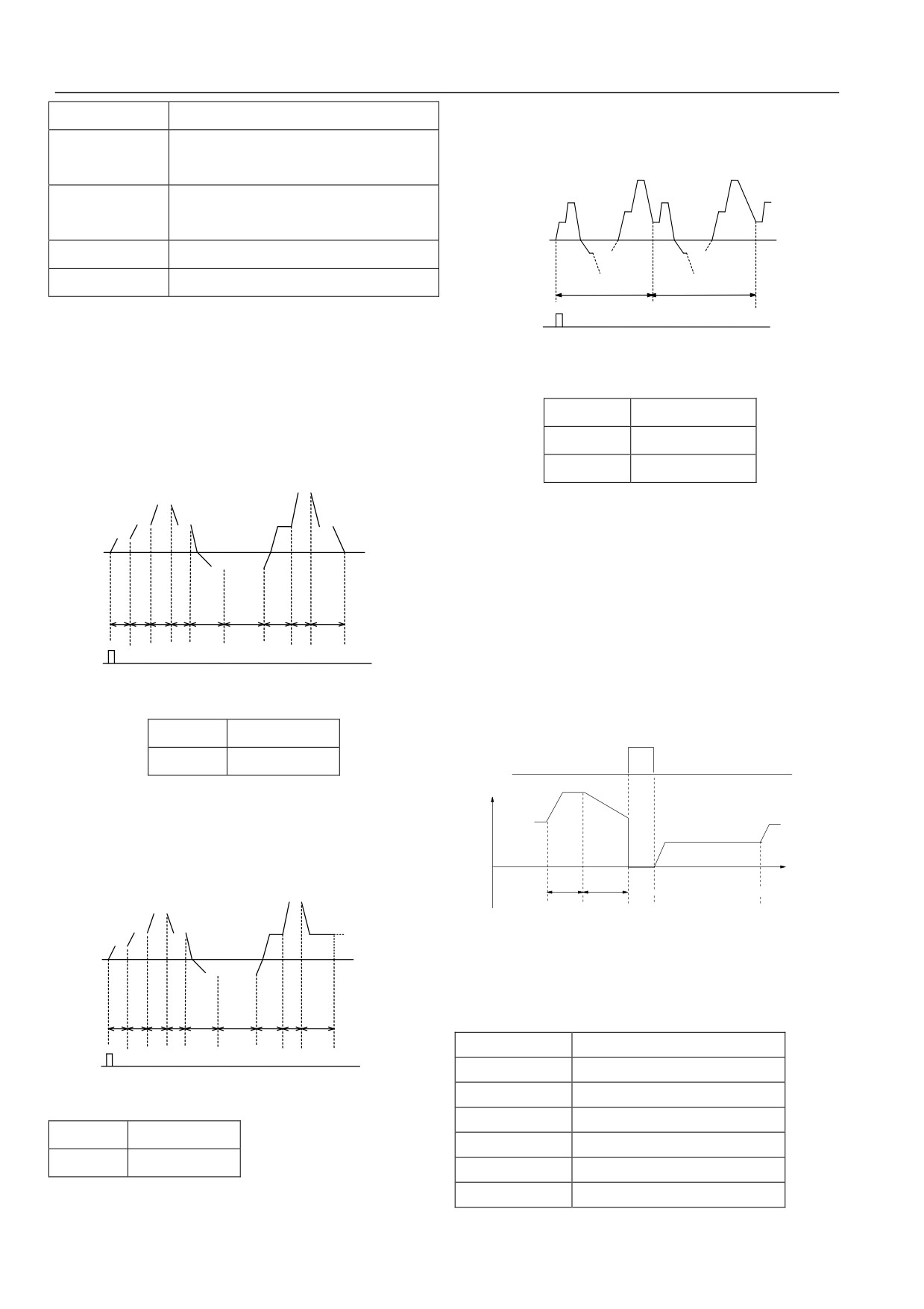
3 (continuous cycle):as shown in Fig.6-83, servo driver will
automatically proceed to the next cycle after completing a cycle,
储存掉电时刻的
Store the phase and frequency at the
till a stop command is given.
power-down moment of
阶段、频率
f15
f5
阶段时间单位选
Phase time unit option
f2
f2
f
4
f1
f14
择
f1
f1
a1
秒
Second
f3
f3
分
Minute
The first
The second cycle
cycle
Ones place: PLC run mode option
R
UN
command
0: non-operating
Fig.6-83 PLC Continuous Cycle Mode
PLC run mode is invalid.
1: stop after single cycle
第一次循环
The first cycle
As shown in Fig.6-81, servo driver will automatically stop after
第二次循环
The second cycle
completing a cycle and it can start only after a run command is
given again.
RUN 命令
RUN command
f
4
f
a
15
3
d4
a14
Tens place: restart mode option after PLC run interruption
f2 a 3
f4
f
f
2
3
5
d15
f1 a
d5
0: rerun from the first phase
PLC run
a1
a 13
d13
If servo driver stops (arising from stop command, fault or power
a 5 f5
down) when running, it will rerun from the first phase after restart.
1: continue running at the phase frequency at the stop (or fault)
T12
T15
T1 T2 T3 T4 T5 T 6 ~
13
14
moment
RUN
If servo driver stops (arising from stop command or fault) when
comman
d
running, it will automatically record the already-running time in
current phase and automatically enter the phase after restart, and
Fig.6-81 Stop Mode after PLC Single Cycle
moreover, continue running of remaining time at the frequency
PLC 运行
PLC run
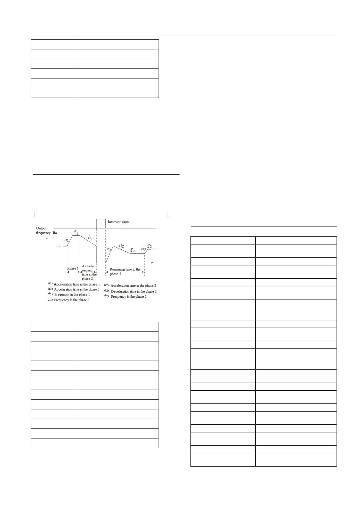
defined in the phase, as shown in the figure below:
RUN 命令
RUN command
Interrupt signal Interrupt
Output
signal Interrupt signal
f1
frequency Hz
d2
2: Keep final value after single cycle
a1
f3
As shown in Fig.6-82, servo driver will automatically keep the
a3
f2
running frequency and direction in the final phase after
a2
completing a cycle.
Phase 1
1Already-running
Remaining time in
Time t
f
4
time in the phase 2 the phase 2
f3
d4
a14
a
15
a 2:: Acceleration time in the phase 2
f2 a 3
f4
f
a1
:Acceleration time in the phase 1
d2
2
3
f
5
:Frequency in the phase 2
a3
:Acceleration time in the phase 3
f2:Frequency in the phase 2
f1 a
d5
a 13
PLC run
a1
f1
: Frequency in the phase 1
d13
a 5 f5
f3:Frequency in the phase 3
T12
T15
Fig.6-84 PLC Start Mode 1
T1 T2 T3 T4 T5 T 6 ~
13
14
输出频率
Output frequency
RUN
comman
中断信号
Interrupt signal
d
阶段 1
Phase 1
Fig.6-82 Keeping Mode of PLC Single Cycle
阶段 2 已运行时间
Already-running time in the phase 2
PLC 运行
PLC run
阶段 2 剩余时间
Remaining time in the phase 2
RUN 命令
RUN command
时间
Time
阶段 1 加速时间
Acceleration time in the phase 1
94
Chapter VI Function Code Details
阶段 2 加速时间
Acceleration time in the phase 2
0: not stored
阶段 3 加速时间
Acceleration time in the phase 3
Not memorize PLC running state in case of power down; rerun
阶段 2 减速时间
Deceleration time in the phase 2
from the first phase after restart upon power on.
1: store the phase and frequency at the power-down moment
阶段 1 频率
Frequency in the phase 1
Memorize PLC running state in case of power down, including the
阶段 2 频率
Frequency in the phase 2
phase, running frequency and already-running time at the
阶段 3 频率
Frequency in the phase 3
power-down moment. After power on, it runs according to the
restart mode after PLC run interruption defined in the tens place.
2: continue running at the running frequency at the stop (or fault)
Thousands place: phase time unit option
moment
0:s
If servo driver stops (arising from stop command or fault) when
Running time in each phase is in seconds.
running, it not only will automatically record the already-running
1:min
time in current phase but also will record the running frequency at
Running time in each phase is in minutes.
the stop moment; after restart, servo driver will first return to the
The unit is valid only to the definition of PLC run phase time T1~
running frequency at the stop moment and then continue running
T15. Selection of acceleration and deceleration time unit during
in remaining phases, as shown in Fig. 6-85.
PLC run is determined by P14.09.
Attention
Attention
The difference between mode 1 and mode 2 is that mode 2
memorizes a running frequency at the stop moment more than
1. When PLC running time in a phase is set as zero, the
mode 1 and servo driver continues running at the frequency
phase is invalid.
after restart.
2. The pause, fault and memory state clearing of PLC
process can be realized by terminals, see the definition of
terminal function in the P10 group.
P15.01 Setting in the phase 1
000~323H【000】
P15.02 Running time in the
0~6500s (min)【20.0s】
phase 1
P15.03 Setting in the phase 2
000~323H【000】
P15.04 Running time in the
0~6500s (min)【20.0s】
phase 2
P15.05 Setting in the phase 3
000~323H【000】
P15.06 Running time in the
0~6500s (min)【20.0s】
phase 3
P15.07 Setting in the phase 4
000~323H【000】
P15.08 Running time in the
0~6500s (min)【20.0s】
Fig.6-85 PLC Start Mode 2
phase 4
P15.09 Setting in the phase 5
000~323H【000】
输出频率
Output frequency
P15.10 Running time in the
中断信号
Interrupt signal
0~6500s (min)【20.0s】
phase 5
阶段 1
Phase 1
P15.11 Setting in the phase 6
000~323H【000】
P15.12 Running time in the
阶段 2 已运行时间
Already-running time in the phase 2
0~6500s (min)【20.0s】
phase 6
阶段 2 剩余时间
Remaining time in the phase 2
P15.13 Setting in the phase 7
000~323H【000】
时间
Time
P15.14 Running time in the
0~6500s (min)【20.0s】
phase 7
阶段 1 加速时间
Acceleration time in the phase 1
P15.15 Setting in the phase 8
000~323H【000】
阶段 2 加速时间
Acceleration time in the phase 2
P15.16 Running time in the
0~6500s (min)【20.0s】
phase 8
阶段 3 加速时间
Acceleration time in the phase 3
P15.17 Setting in the phase 9
000~323H【000】
阶段 2 减速时间
Deceleration time in the phase 2
P15.18 Running time in the
0~6500s (min)【20.0s】
阶段 1 频率
Frequency in the phase 1
phase 9
P15.19 Setting in the phase 10
000~323H【000】
阶段 2 频率
Frequency in the phase 2
P15.20 Running time in the
0~6500s (min)【20.0s】
阶段 3 频率
Frequency in the phase 3
phase 10
P15.21 Setting in the phase 11
000~323H【000】
P15.22 Running time in the
0~6500s (min)【20.0s】
Hundreds place: PLC state parameter storage option in case of
phase 11
power down
95
Chapter VI Function Code Details
P15.23 Setting in the phase 12
000~323H【000】
Setting of LED ones place in the PLC phase i:
P15.24 Running time in the
0: select multi-phase frequency i
0~6500s (min)【20.0s】
phase 12
For example, when i is equal to 3, the frequency of phase 3 is
P15.25 Setting in the phase 13
000~323H【000】
multi-phase frequency 3; for definition of multi-phase frequency,
P15.26 Running time in the
0~6500s (min)【20.0s】
phase 13
see the P16.00~P16.14.
P15.27 Setting in the phase 14
000~323H【000】
1: the frequency is determined by main set frequency source
P15.28 Running time in the
0~6500s (min)【20.0s】
function code P02.03.
phase 14
P15.29 Setting in the phase 15
000~323H【000】
2: I multi-phase closed loop given
P15.30 Running time in the
For example, when i is equal to 2, the frequency of phase 2 is
0~6500s (min)【20.0s】
phase 15
multi-phase closed loop given 2; for definition of multi-phase
P15.01, P15.03, P15.05, P15.07, P15.09, P15.11, P15.13, P15.15,
closed loop given, see the P13.20~P13.34.
P15.17, P15.19, P15.21, P15.23, P15.25, P15.27 and P15.29 are
3:determined by closed loop given channel function code P13.01
used
to
set
running
frequency,
direction
and
PLC can realize closed loop running in a phase; closed loop given
acceleration/deceleration time in each PLC phase, selected by
channel can be multi-phase closed loop given i or determined by
places. As shown in Fig. 6-86.
P13.01 function code; feedback channel is determined by P13.0.
Hundre
Tens
Ones
When given channel is determined by P13.01 function code, the
s place
place
place
closed loop given channel can be switched to multi-phase closed
Frequency setting
loop given value by the option terminal of multi-phase closed loop
0:Multi-phase frequency i
given. See the terminal functions 30, 31 and 32 of function codes
Determined by P02.03 function code
P10.00~P10.07 and detailed description of P13.20~P13.34.
2:
Multi-phase closed loop given
i
D:etermined by P13.01 function code
Attention
When PLC phase running direction is determined by run
Running direction option
command, running direction of motor can be changed in a
0 :Fo rward
real-time way by external direction command. For example,
1:Reverse
2 Determined by run command
realize forward running by FWD-COM and realize reverse
running by REV-COM. Running direction is determined by
Acceleration/deceleration time
run command; if the direction can not be determined, it
option
0:
Acceleration/deceleration time 1
follows the running direction in the previous phase.
1:
Acceleration/deceleration time 2
2:
Acceleration/deceleration time
3
6.1.17 Multi-speed parameters (P16 group)
3:
Acceleration/deceleration time 4
Fig.6-86 Setting in the PLC Phase i (i=1~15)
P16.00 Multi-phase
Lower frequency limit ~Upper frequency
个位
Ones place
frequency 1
limit
【5.00Hz】
十位
Tens place
P16.01 Multi-phase
Lower frequency limit ~Upper frequency
百位
Hundreds place
frequency 2
limit
【10.00Hz】
频率设置
Frequency setting
P16.02 Multi-phase
Lower frequency limit ~Upper frequency
frequency 3
limit
【20.00Hz】
多段频率 i
Multi-phase frequency i
P16.03 Multi-phase
Lower frequency limit ~Upper frequency
由 P02.03 功能码决定
Determined by P02.03 function code
frequency 4
limit
【30.00Hz】
多段闭环给定 i
Multi-phase closed loop given i
P16.04 Multi-phase
Lower frequency limit ~Upper frequency
由 P13.01 功能码决定
Determined by P13.01 function code
frequency 5
limit
【40.00Hz】
运转方向选择
Running direction option
P16.05 Multi-phase
Lower frequency limit ~Upper frequency
frequency 6
limit
【45.00Hz】
正转
Forward
P16.06 Multi-phase
Lower frequency limit ~Upper frequency
反转
Reverse
frequency 7
limit
【50.00Hz】
由运行命令确定
Determined by run command
P16.07 Multi-phase
Lower frequency limit ~Upper frequency
加减速时间选择
Acceleration/deceleration time option
frequency 8
limit
【5.00Hz】
加减速时间 1
Acceleration/deceleration time 1
P16.08 Multi-phase
Lower frequency limit ~Upper frequency
frequency 9
limit
【10.00Hz】
加减速时间 2
Acceleration/deceleration time 2
P16.09 Multi-phase
Lower frequency limit ~Upper frequency
加减速时间 3
Acceleration/deceleration time 3
frequency 10
limit
【20.00Hz】
加减速时间 4
Acceleration/deceleration time 4
P16.10 Multi-phase
Lower frequency limit ~Upper frequency
frequency 11
96
Chapter VI Function Code Details
limit
【30.00Hz】
frequency 15
limit
【50.00Hz】
P16.11 Multi-phase
Lower frequency limit ~Upper frequency
frequency 12
limit
【40.00Hz】
These frequencies will be used in the multi-speed run mode and
P16.12 Multi-phase
Lower frequency limit ~Upper frequency
simple PLC run mode, see the detailed description of multi-speed
frequency 13
limit
【45.00Hz】
run terminal functions “1”, “2”, “3” and “4” in 6.1.11 switching
P16.13 Multi-phase
Lower frequency limit ~Upper frequency
input terminal P10.00~P10.07 and P15-group function codes in
frequency 14
limit
【50.00Hz】
P16.14 Multi-phase
Lower frequency limit ~Upper frequency
6.1.16 simple PLC.
个位
Ones place
6.1.18 LED display parameters (P17 group)
十位
Tens place
P17.00 LED run display parameter
输出电压
Output voltage
000~3F7H【007H】
option 1
模拟闭环反馈
Analog closed loop feedback
Hundred
Tens
Ones
s place
place
place
模拟闭环设定
Analog closed loop setting
BIT0 :
Output
: Hz:
frequency
端子状态
Terminal state
BIT1
: Set frequency (Hz flicker)
BIT2
:Output currentA:
Displayed terminal state includes multi-function terminals X1~
B:T0 : Running spee
:
RPM :
BIT1 : Set
speed (RPM flicker)
X8 and FWD and REV terminals; LED digital tube specified
BIT2 :Running linear speed(M/S)
BIT3
:
Set linear speed (m/s
value is used to indicate the state of each function terminal. For
flicker)
example, when X1, X2 and FWD terminals are closed and other
BIT0 :Output power
terminals are disconnected, displayed terminal state value is 103H.
Fig.6-87 Setting of LED Run Display Parameter Option 1
For terminal sequence, see the description of P10.16.
个位
Ones place
Attention
十位
Tens place
When running speed and line speed are displayed, they can be
modified in a real-time way by
▼ and ▲ keys (it is
百位
Hundreds place
unnecessary to switch to frequency state).
输出频率
Output frequency
When both P17.00 and P17.01 are 0, default display is output
frequency.
设定频率(Hz 闪烁)
Set frequency (Hz flicker)
In the display state of run parameter, display parameters can
输出电流
Output current
be switched successively by shift key
运行转速
Running speed
Hundred
Tens
Ones
设定转速(RPM 闪烁)
Set speed (RPM flicker)
s place
place
place
运行线速度
Running line speed
BIT0 Set frequenc: Hz :
BIT1:Running spe
: RPM:
设定线速度(m/s 闪烁)
Set line speed (m/s flicker)
BIT2 :Set spee: RPM:
BIT3 :Bus voltage: V :
输出功率
Output power
BIT0
Running linear speed(R/S)
BIT1 Set linear speed(m/s)
BIT2A nalog closed loop feedback
BIT3 Analog closed loop setting
P17.00 and P17.01 define the state parameter displayed by LED
when servo driver is in running state.
BIT0 : AI1 : V :
When BIT place is 0, the parameter is not displayed.
BIT1 : AI2 : V :
BIT2 : AI3 : V :
When BIT place is 1, the parameter is displayed.
Fig.6-89 Setting of LED Stop Display Parameter Option
For example, LED ones place-BIT0 is the display switch code of
“output frequency”; when BIT0 is equal to 0, the parameter is not
P17.02 LED stop display
000~FFFH【009H】
displayed; when BIT0 is equal to 1, the parameter is displayed.
parameter option
Ones place
P17.01 LED run display parameter
00~FFH【00H】
option 2
个位
Tens place Ones place
十位
Tens place
百位
Hundreds place
BIT0:Output volta
: V:
BIT1 : AI1 : V :
BIT2 : AI2 : V :
设定频率
Set frequency
BIT3 : AI3 : V :
运行转速
Running speed
BI
:Analog closed loop feedback
BIT
:Analog closed loop setting
设定转速
Set speed
BIT2:Terminal state
母线电压
Bus voltage
Fig.6-88 Setting of LED Run Display Parameter Option 2
运行线速度
Running line speed
97
Chapter VI Function Code Details
Set line speed
Hundred
设定线速度
Tens place
Ones place
s place
模拟闭环反馈
Analog closed loop feedback
Baud rate option:
0: 4800bps
模拟闭环设定
Analog closed loop setting
1: 9600bps
2: 19200bps
3: 38400bps
4: 112500bps
5: 125000bps
The parameter defines the state parameter displayed by LED when
Data forma:
servo driver is in stop state.
0: 1-8-2-N Forma: RTU
t
1: 1-8-1-E
FormatRTU
2: 1-8-1-O
Format
: RTU
When BIT place is 0, the parameter is not displayed.
3: 1-7-2-N
Format:ASCII
4: 1-7-1-E
Format:ASCII
When BIT place is 1, the parameter is displayed.
5: 1-7-1-O
Format:ASCII
For example, BIT0 is the display switch code of “set frequency”;
Connection mode:
when BIT0 is equal to 0, the parameter is not displayed; when
0 :Direct cable connection(RS485)
1: MODEM Connection
BIT0 is equal to 1, the parameter is displayed.
RS232/RS485 conversion is required
Attention
Fig.6-90 Setting of Communication Configuration
When running speed and line speed are displayed, they can be
个位
Ones place
modified directly by ▼ and ▲ keys (it is unnecessary to
十位
Tens place
switch to frequency state).
When P17.02 setting values are all 0, default display is set
百位
Hundreds place
frequency.
波特率选择
Baud rate option
In the display state of stop parameter, display parameters can
be switched successively by shift key
数据格式
Data format
格式
Format
P17.03 Speed display
0.1%~999.9%【100.0%】
接线方式
Connection mode
coefficient
直接电缆连接
Direct cable connection
The function code is used to correct the display error of speed
scale and it has no influence on actual speed.
MODEM 连接
MODEM Connection
P17.04 Line speed coefficient
0.1~999.9%【1.0%】
需要 RS232/RS485 转换
RS232/RS485 conversion is required
The function code is used to correct the display error of line speed
scale and it has no influence on actual speed.
The function code is set by LED place mode and it is used for
P17.05 Closed loop analog
0.1~999.9%【100.0%】
parameter selection of serial communication port.
display coefficient
Setting of hundreds place has no influence on processing of
communication process, but when the function code is set as
The function code is used to correct the display error between
MODEM mode, MODEM will be initialized by means of RS485
actual physical quantity (pressure , flow rate, etc.) and given or
port on the control panel whenever servo driver is power-on, so
feedback quantity (voltage and current) under closed loop control
that MODEM can automatically answer after receiving the ringing
signal of telephone line thrice, to realize the remote control line
and it has no influence on closed loop regulation.
composed of dialup lines; for connection mode, see 4.2 control
circuit wiring and configuration.
6.1.19 Communication parameters (P18 group)
Attention
P18.00 Protocol option
0~1【0】
HSD2000 control panel only provides RS485 interface. If
Communication protocol option
communication interface of external device is RS232
(e.g.
0: Modbus protocol;
external communication interface is RS232 modem), an
RS232/RS485 conversion device is needed.
1: Reserved
P18.02 Local address
0~247【5】
P18.01 Communication
In the serial port communication, the function code is used to
000~155H【001】
configuration
identify the address of local servo driver.
Attention: 0 is broadcast address. When set as broadcast address,
it can only receive and execute the broadcast command of upper
computer and can not respond to the upper computer.
P18.03 Communication time-out
0~1000.0s【0.0s】
detection time
98
Chapter VI Function Code Details
When the serial port communication signal disappears, if the
P20.00 defines the protection operating option when
duration thereof exceeds the setting value of the function code, it
communication, contactor and EEPROM are abnormal and in the
can be concluded that servo driver has a communication fault.
case of 24V short circuit.
When setting value is 0, servo driver does not detect the serial port
Thousand
Hundreds
Tens
Ones
s place
place
place
place
communication signal, i.e. the function is invalid.
Operating option when communication is
P18.04 Local response delay
0~1000ms【5ms】
abnormal
0:Protection operates and stop freely
(E017)
1:
Give an alarm and continue running (A017)
Local response delay refers to the delay time needed from the
ive an alarm and report A017 to stop by stop
2G
mode; report E017 after stop (only in the
serial port of servo driver receiving and interpretively executing a
Give an alarm and report A017 to stop by
serial port control mode)
3: stop mode; report E017 after stop (in all
control modes)
command from the upper computer to returning a response frame
Operating option when the contactor is
to the upper computer; the function code is used to set the delay
OperaProtection operates and stopr is
0:
freely(E018)
Give an alarm and continue
time. For RTU mode, actual response delay is not less than the
1:
running(A018)
transmission time of 3.5 characters.
Operating option when EEPROM is abnormal
0Protection operates and stop freely(E016)
1G
ive an alarm and continue running(A016)
P18.05~P18.09
Reserved
Operating option in the case of 24V short
circuit
Reserved function
Protection operates and stop freely(E016)
1:
Give an alarm and continue running(A029)
P18.10~P18.19
00.00~99.99【99.99】
Fig.6-91 Setting of Protection Operating Option 1
Address mapping of input parameter
个位
Ones place
It is used to map the parameter to be inputted. Integral part
corresponds to the group number of the parameter and decimal
十位
Tens place
part corresponds to the index in the group (serial number of the
百位
Hundreds place
parameter in the group).
千位
Thousands place
For example, set P18.10=02.01, and it shows the function code
通讯异常动作选择
Operating option when communication is
P02.01 is mapped to input parameter 1.
abnormal
P18.20~P18.29
00.00~99.99【99.99】
保护动作并自由停车
Protection operates and stop freely
Address mapping of output parameter
告警且继续运行
Give an alarm and continue running
It is used to map the parameter to be outputted. Integral part
告警报 A017 按停机方式
Give an alarm and report A017 to stop by
corresponds to the group number of the parameter and decimal
停机,停机后报 E017(仅
stop mode; report E017 after stop (only in
part corresponds to the index in the group (serial number of the
the serial port control mode)
parameter in the group).
串行口控制方式下)
For example, set P18.20=01.01, and it shows the function code
告警报 A017 按停机方式
Give an alarm and report A017 to stop by
P01.01 is mapped to output parameter 1.
stop mode; report E017 after stop (in all
停机,停机后报 E017(所
control modes)
Attention
有控制方式下)
When rewriting P18.20 ~ P18.29 via communication, a
接触器异常动作选择
Operating option when the contactor is
hexadecimal number can be written in directly to facilitate
abnormal
operation; for example, write 0x2034 in the P18.21, and the
EEPROM 异常动作选择
Operating option when EEPROM is
function code P20.34 is mapped to output parameter 2.
abnormal
24V 短路动作选择
Operating option in the case of 24V short
6.1.20 Bus communication parameters (P19 group)
circuit
Temporarily Reserved.
保护动作并自由停车
Protection operates and stop freely
6.1.21 Protection parameter and fault record (P20
告警且继续运行
Give an alarm and continue running
group)
P20.00 Protection operating
0000~1113【0000】
Attention
option 1
P20.01 Protection operating
If the operating option in the case of 24V short circuit is “1”,
00~23【00】
option 2
once a 24V short circuit fault arises and the fault does not
disappear, servo driver will give an alarm and run for 15min,
and then automatically report E029.
When servo driver is in some abnormal states, its fault and stop
P20.01 defines the protection operating option when an input
can be masked by setting protection operating option (P20.00 and
/output phase fails and when an external analog frequency/torque
P20.01), to keep running. Here operating panel will display a fault
instruction is missing
alarm A0×× (×× represents alarm code; for details, see Chapter
VII Measures relative Fault Alarm, Handling of Abnormality);
the frequency of continuing running in alarm state is described in
the setting of function code P20.04.
99