HSD2000 Series Servo Drive. Operation Manual V1.2 - page 3
Chapter VI Function Code Details
For position instruction given channel of HSD2000 position control mode, refer to refer to P09 group function code detailed description of
function code detailed introduction in chapter VI.
5.3The First Power up
5.3.1Checking before Power up
The connection connection shall be implemented as technical requirements in Chapter IV Servo Drive Connection and EMC
Installation Instructions of chapter IV.
5.3.2The First Power Up Operation
When wiring and power supply is correct, close air switch of AC power supply in servo drive input side; charge to servo drive; “8.8.8.8.8.”
will be displayed on servo drive operation panel; the contactor will be picked closely. When digital tube display symbol is setting
frequency, the initialization of servo drive will be finished.
When LED indicator on digital tube of operation panel is ON state, the operation panel is in control state.
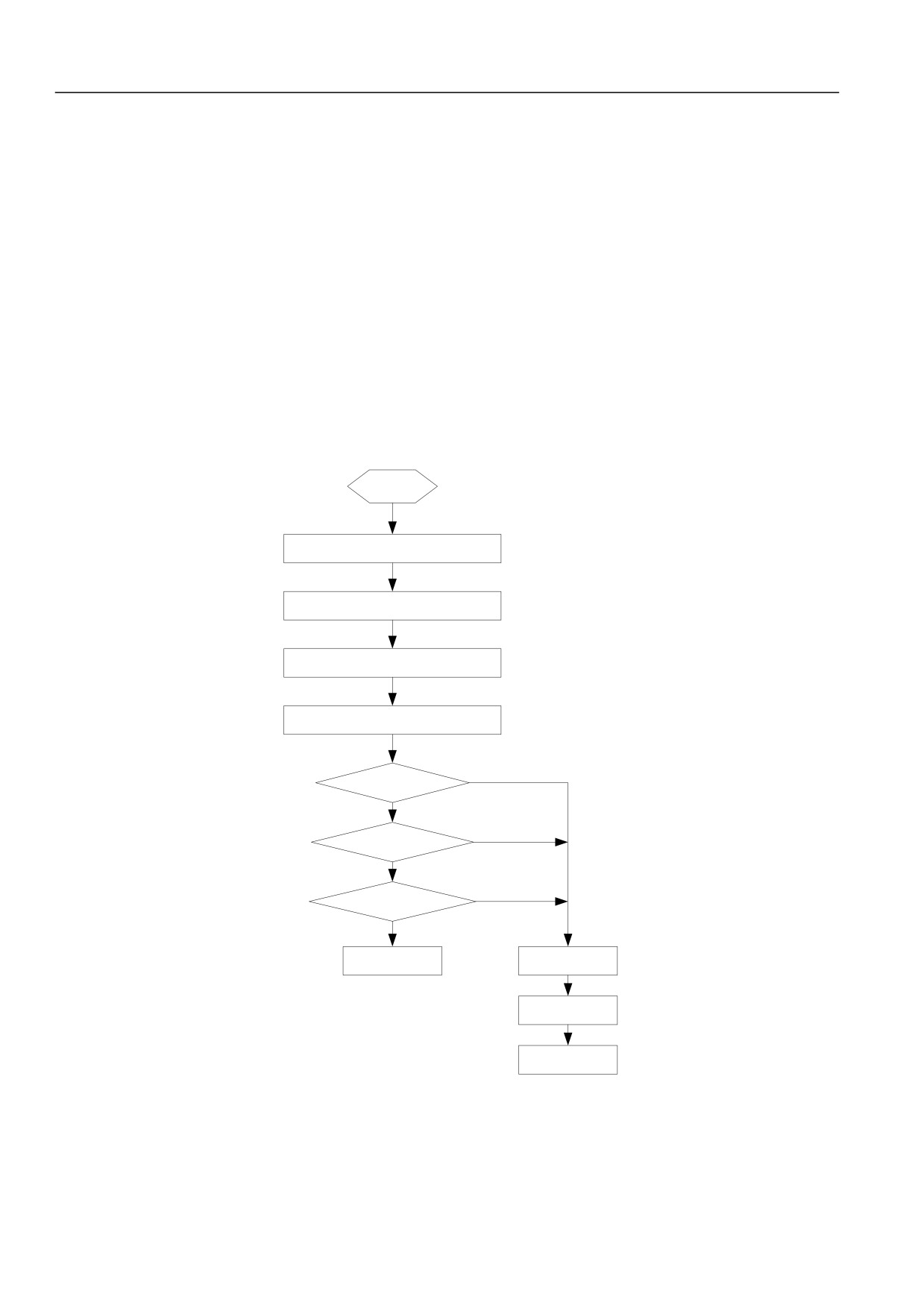
The first power up process is shown as figure below:
Start
Connection according to the
requirements
Check the connections
Check the input voltage
Power up
N
Display 8.8.8.8.8?
Y
Hear the contactor
N
closed?
Y
N
Display set frequency?
Y
Power up ok
Power up failed
Disconnect the
input air switch
Check the circuit
Figure 5-9: servo drive power up
40
Chapter VI Function Code Details
5.4Pilot running
5.4.1 Sensorless Vector Pilot Running
1.Inspect drive input and output connections. Power up shall be implemented after without error.
2.Enter P03 group to input motor parameter correctly. Set P03.11=2 (remove load) to tune the motor parameters.
3.Set P02.00 as no PG vector control.
4.Running
5.4.2Closed-loop Vector Pilot Running
1. Inspect drive input and output connections. Power up after without error.
2. Enter P03 group to input motor parameter correctly. Set P03.11=2 (remove load) to tune the motor parameters.
3.Set encoder signal feedback source correctly, when expansion PG card is selected as signal feedback, then set P07.00=1. When
select local terminal as signal feedback, then set P07.00=0. The P12 group parameter shall be set as selected signal feedback.
4.The control mode set as V/F control mode of P02.00=2. The operation frequency set as P02.04=10.00Hz.
5.Run the motor and observe P01.13 values. When the value closes to 10Hz, it shows that encoder parameter is correct. When the
value is negative, it shows direction error of encoder. Exchange any two of the three phase motor wires. When the frequency is 0, it
represents that encoder is not connected correctly. Encoder shall use shielding layer and connect to control terminal PE of servo drive.
When the frequency is not correct, it represents that the encoder wires or motor rated speed setting error. The related function code shall be
changed.
6.The control mode set as closed-loop vector of P02.00=1(induction motor close loop vector control).
7.Set the frequency from 0 to rated frequency. The motor stable and vibration shall be noted, especially around 0. When vibration
occurs around 0 frequencies, the encoder low speed wave filter parameter P12.03/P12.14 and speed loop PI parameter P07 group shall
be adjusted. It shall be finished until stable operation without vibration in the entire frequency range.
5.4.3Torque Control Pilot Running
1.Do the step 5.4.1(open-loop mode) or 5.4.2(closed-loop mode) to ensure drive normal.
2.The control mode set as torque control P08.00=1.
3.Set torque instruction given of P11.01=8. AI1 is channel of torque instruction.
4.Set speed limit mode, P07.08=1.
5.Set speed limit channel, P07.09=1。
6.Set speed limit instruction, P11.06=4, AI2 is speed limit channel.
7.Applicable set speed/torque switching point P08.04.
5.4.4Servo Control Pilot Running(X7 and X8 terminal pulse serial control as example)
1.The 5.4.2 methods may be used to ensure drive PG closed-loop vector control for normal operation.
2.Set servo function P09.00=3.
3.Set position given source P09.03=0; set X7 and X8 terminal function as P10.06=71, P10.07=72; The position given is entered
by terminalX7 and X8input. The X7 represents direction, X8 represents pulse serial. X7 shall be forward when no conducting. X7 shall be
reverse when conducting. The reverse may be taken reverse of X7 by P10.16.
4.Set P10.11 (each pulse number of X8). The follow rotational speed shall be obtained by X8 pulse frequency. The rotational speed
value is not related with electronic gear function (P09.10, P09.11).
5.Set P09.10 and P09.11 (electronic gear numerator, denominator). When motor follows pulse serial, relationship between encoder
feedback number and pulse serial number shall be electronic gear ratio relationship.
41

Chapter VI Function Code Details
6.Example: the motor shall be 4 degree motor. The encoder shall be 1024-coil. When pulse serial is 100k, the rotational speed of
Corresponding motor is required to be 1500rpm. P10.11=100k*60/1500=4000 shall be set; electronic gear ratio= (1024*1500/60)
/100K=256/1000, P09.10=256 may be set; P09.11=1000.
7.Adjust speed loop PI parameter and position loop P parameter P09.26 (position loop Kp1), P09.27 (position loop Kp2), P09.28
(position loop increment switch mode). The pulse serial track process shall be fast without overload. The P09.08 may be set as
requirements (pulse instruction wave filter time). The pulse tracking error shall be monitored by function code P01.47 at real time.
8.Before debugging, the P09.34=0 ( position loop output range) may be set. It is speed tracing mode at this time. The speed shall be
observed for normal. Then the position loop shall be added to monitor position. The P09.33 (Velocity feed forward gain) shall be set as
100.00%. The parameter value shall be not changed.
5.4.5Spindle Positioning Pilot Running
1.According to 5.4.2 method, the drive PG closed-loop vector control shall be ensured for normal.
2.The servo operation mode shall be spindle operation, P09.01=2.
3. Set the X1~X5 terminal function as 84, 77, 78, 79, 37. X1 shall be zero origin. X2 shall be spindle position start. X3 and X4
shall be position selection terminal. X5 shall be prohibited running terminal of servo drive.
4.Set unit digital value of positioning mode P09.02. The electric spindle shall equip encoder Z pulse as reference point. The
non-electric spindle shall equip close switch. The closing switch shall be used to refer zero point. During operation, the spindle will
search reference point automatically. The function code setting is not necessary.
5.When using the X1or X3, X4, the motor will stop after an angle of rotation. The zero position shall be observed for consist. The
degree shall be correct.
6.Adjust speed loop PI parameter and position loop P parameter P09.26 (zero servo locking position loop KP), P09.27 (position
process position loop KP). The position process shall be fast without overshoot.
5.4.6Synchronous Motor Pilot Running(Increment ABZUVW Encoder as Example)
1.Inspect drive input and output wiring; inspect PG card wiring. Power shall be implemented after no error.
2. The control mode shall be set as PG closed-loop vector; P02.00=11.
3.Set PG parameter correctly; PG feedback resource P07.00;
4.The motor parameter P03 group shall be set correctly. The tuning P03.23 of motor shall be implemented.
5.When tuning the motor, send the DC first, turn the motor to certain position and low speed rotation. When current is smaller with
stable operation, it represents that encoder setting correct with success tuning. When report E025 in tuning process, it represents
encoder wiring problem. The encoder shall be connected again. After tuning, the function code P03.25, P03.26 will save initial angular
of synchronous machine obtained by tuning. When the initial angle difference is smaller than 5
(65536 represents 360°), it represents
the tuning in normal.
6. When the tuning is abnormal without E025 fault, P12.16,P12.19,P12.21 shall be observed to determine for encoder signal
problems. Encoder shall be checked to solve problem. When rotate the motor shaft, when P12.19 count value increases, the P12.16
displays the magnetic signal status order of 5, 1, 3, 2, 6, 4. When the count value reduces, the order of magnetic signal shall be reverse.
When 0 or 7 be happened in P12.16, magnetic signal UVW wiring of encoder shall be not correct. After one round rotation, Z pulse
count value of P12.21 shall be not 0. Otherwise the Z signal has problems.
7. Set the frequency from 0 to rated frequency. The motor stable and vibration shall be noted, especially around 0. When vibration
occurs around 0, the encoder low speed wave filter parameter P12.03/P12.14 and speed loop PI parameter P07 group shall be set.
8. During operation, the encoder Z pulse count value P12.21 shall be observed. When the value jumps higher, it shows disturb of
encoder. The encoder wiring shall be checked.
Note
When P12.08 value is 1, when rotate the motor shaft, if the P12.19 count value reduces, the P12.16 display magnetic signal status
order shall be 5, 1, 3, 2, 6, 4. When the count increases, the magnetic signal order shall be reverse.
42
Chapter VI Function Code Details
When the user password function is needed: first input four digits
as user password; press DATA/ENTER key to ensure; password
Chapter VI Function Code Details
will take effects automatically when without key operation in 5
minutes.
Password modifying:
6.1 Function Code Description
Press MENU/ESC key to enter password verification status. After
input original four digits password to enter parameter editing
In the section:
status, the P00.02 (at this time P00.02=00000) shall be selected.
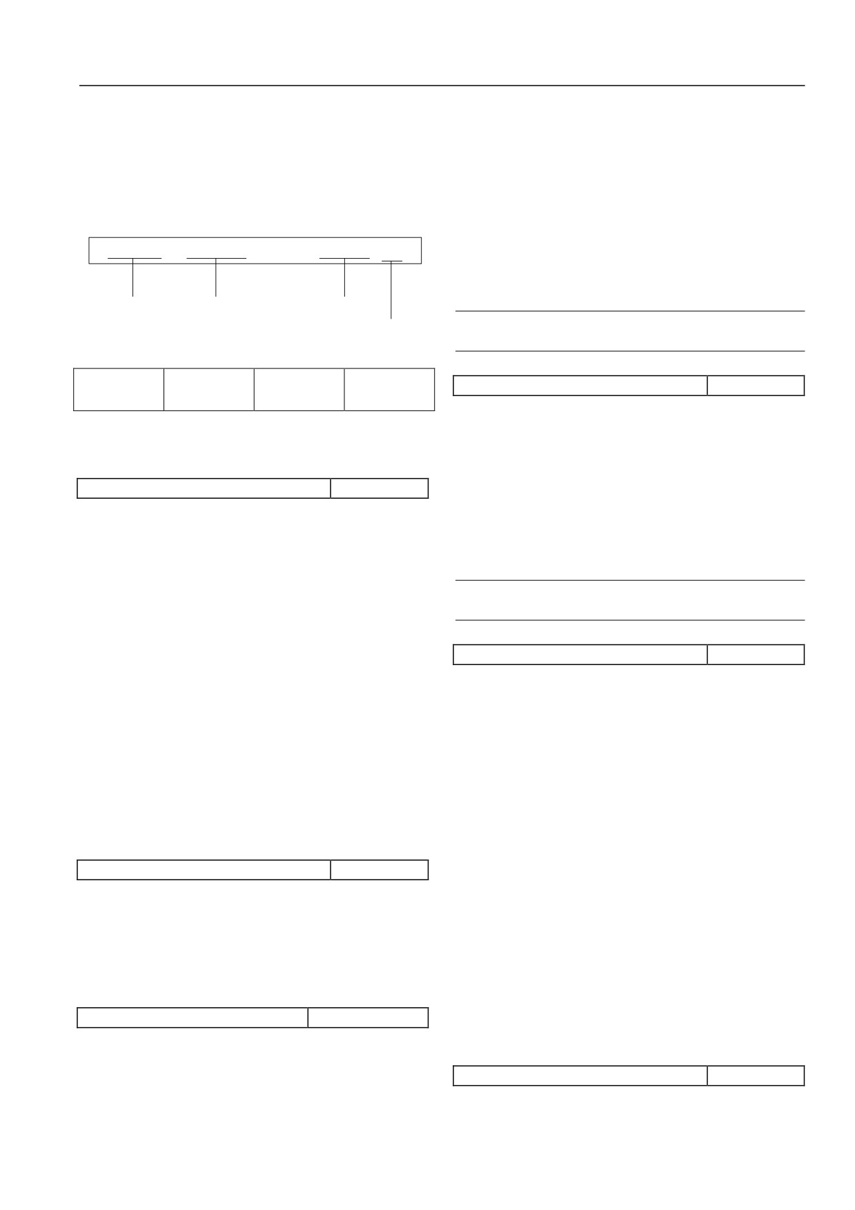
PXX.XX YYYYYYY
N1~N2 [D]
Input new password; enter DATA/ENTER key to ensure. New
password will take effects automatically when without key
operation in 5 minutes.
Function
Function code
Function code
code
name
range
Note
Function code
default
Please save setting user password carefully.
Function code
Function code
Function code
Function code
P00.03 Parameter protection setting
0~2【0】
number
name
range
default value
The setting of function code determines protective degree of servo
drive parameter which includes:
0: All the data may be allowed to modify.
6.1.1System management (P00 group)
1: Modify is not allowed except main setting frequency digital
P00.00 Menu mode option
0~4【2】
setting P02.04 and the function code.
0: Shortcut menu mode
2: All the data shall be not allowed to modify except the function
code.
The parameter related with quick operation servo drive shall be
displayed. The servo drive shall be started quickly by modify
When finish modifying parameter, when protect the parameters,
parameter under menu mode.
the function code shall be set as desired protection degree.
1: Basic menu mode
Note
Only the parameters related with basic operation shall be
P00.03 function code may be displayed at all menu modes.
displayed. It doesn’t include basic applicable functions of
enhanced control parameter, expansion card parameter and
P00.04 parameter initialization
0~4【0】
customization features parameter.
0: Parameter modifying status
2: Advanced menu mode
When the function code saves into parameter 0, all the parameters
Display all the parameters
shall be modified.
3: User menu mode
1: Clear fault memory information
Only 32 parameters prepared in P98 group of users shall be
When the function code saves into parameter 1, zero clearing
displayed.
operation shall be implemented to fault record (P20.21~P20.35).
4: Proof menu mode
2: Reset factory setting value
Only parameters different with factory setting value shall be
When save the function code into parameter 2, all the function
displayed.
code parameters shall reset factory parameters except: user
password (P00.02); servo drive status display parameters (P01
P00.01 LCD display language option
0~4【0】
group); motor 1 parameter (P03 group); motor 2 parameter (P04
0: Chinese
group); P20.21~P20.35, P97 group and P98 group.
1: English
3: Only reset quick start function group
2~4: Reserved
When the function code saves into parameter
3, only the
The function is only effective to operation panel configured with
parameters related with quick operation servo drive shall be
LCD.
rested.
4: Only reset customized parameter group
P00.02 user password
00000~65535【00000】
When the function code saves into parameter
4, only the
parameter prepared by user of P98 group shall be set.
The user password setting function is used for stop non-authorized
personnel from referring and modifying function parameter.
When there is no user password, the function code shall be set as
P00.05 parameter copy
0~3【0】
00000.
0: No action
1: Parameter upload
43
Chapter VI Function Code Details
After setting as
1 and ensure, the servo drive will upload all
non-panel
function codes between control panel P00.00 ~ P98.31 to
control
EPPROM of operation panel for storage.
It is effective in operation panel, terminal,
Stop of
serial port operation command channel.
2: Parameter downloading
1
non-panel as
Press the key, the servo drive will stop as
After setting as 2 and ensure, the servo drive will download all
stop mode
P05.05 setting.
function codes between operation panel P00.00 ~ P98.31 to
When running command channel on
internal control panel for storage.
operation panel, press the key, servo drive
Non-panel
3: Parameter downloading (except parameter)
will stop as mode of P05.05. When the
2
control
command channel is operated by terminal
After setting as 3 and ensure, the servo drive will download all
freewheel
or serial port, press the key, the servo drive
function codes between operation panel P00.00 ~ P98.31 to
will be freewheel and report E015 fault.
internal control panel for storage (P03 and P04 group motors
Note
parameters shall be not downloaded).
STOP/RESET key will be effective in any command channel
Note
operation of fault reset key RESET.
1.For operation panel, the parameter uploading shall be
Tens digits: LOCAL key function option
implemented first. Otherwise the operation panel memory will
The item is used for setting working and range of LOCAL key on
be empty. When finish one time parameter loading operation,
operational panel.
operation panel parameter shall be kept in operation panel
memory.
Tens
Function
Description
2.Before the parameters download to servo drive, servo
digits
drive will inspect integrity and version information of function
LOCAL key is invalid. The key shall be not
0
Invalid
code parameter in operation panel. In the following conditions,
used for switch operation command channel.
the parameter shall be not modified and the error information
Stop
LOCAL key is only effective in stop status.
will be mentioned to copy: when the memory is empty;
1
status
The key shall be not used for switch operation
parameter is not full; parameter version is not the same as
effective
command channel.
current servo drive software version (different quantities of
Stop
LOCAL key may switch running command
function codes).
2
operation
channel under stop status and operation
3.After download the parameter, parameter in operation
effective
status.
panel memory is still existed. Multi servo drives shall be
copied repeatedly.
Operation Command Channel Switch Order:
P00.06 key function option
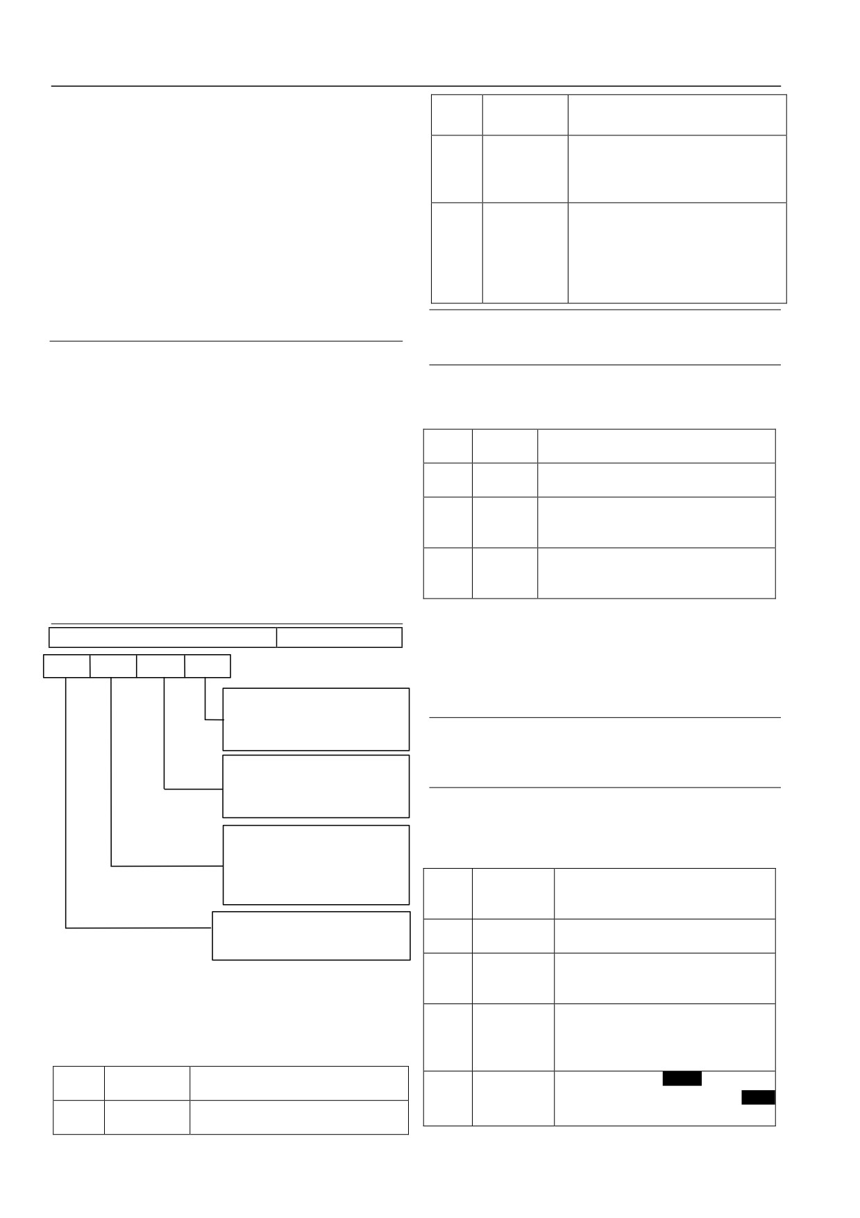
0000~1422H【0000】
Operation panel running command channel
(LOCAL lights)
Tens
Ones
Thousands Hundred
→terminal running command channel
(LOCAL off) →serial
placs
placs
placs
placs
port running command channel (LOCAL flash) →operation panel
Key feature
STOP
running command channel (LOCAL lights)
selection
0 :Panel control method is invalid
1 :Panel control mode in down way down
Note
2 :Panel control mode free parking
After switch to necessary running command channel by
LOCAL Key feature selection
LOCAL key, the DATA/ENTER shall be pressed in 3 seconds
0
:Nullify
for effective.
1 :Effective stop condition
2 :Stop and run effectively
Hundred digits: operation panel locking function
Operation panel locking
options
The item is used for setting locking range option of operation
0: no lock
1: all lock
panel keys.
2: in addition to the STOP key lock
3: in addition to the SHIFT key lock
Hundr
4: all locked except the RUN, the STOP
ed
Function
Description
button
digits
STOPKey double-click the abrupt stop function
No locking function, any key shall be not
:Double click the STOP key free
0
0
No locking
parking
locked.
1: No function
Operation panel key shall be locked fully.
1
Full locking
After the locking function takes effect, any
Figure 6-1: operation panel
key on operation panel will be invalid.
Unit digit: STOP/RESET key function option
All locking
In addition to STOP/RESET key, other keys
except
are all locked. After the locking function
The item is used for setting operation panel STOP/RESET key as
2
STOP/RESE
takes effects, only the STOP/RESET key
working range and run mode in STOP of stop key.
T key
may be used.
Unit
Function
Description
All locking
All locking except
key. After the
digit
3
except SHIFT
locking function takes effect, only
It is effective for operation panel to run
0
Invalid
key
key may be used.
command channel
44
Chapter VI Function Code Details
All locking
In addition to STOP, RUN keys, other keys
Monitor servo drive output current.
except RUN,
are all locked. After the locking function
4
P01.08 torque current
-300.0%~300.0%【0.0%】
STOP/RESE
takes effects, only the STOP, RUN keys
Monitor servo drive percentage of torque current to motor rated
T keys.
may be used.
current.
After setting the items as demands, the specified operation
P01.09 Flux current
0.0%~100.0%【0.0】
methods shall be implemented to make locking effective. Refer to
Monitor percentage of flux current to motor rated current.
05.1.3Operation Mode of Operation Panel operation method.
P01.10 output torque
-300.0%~300.0%【0.0】
The locking method may refer to
05.1.3Operation Mode of
Monitor percentage of servo drive output torque to motor rated
Operation Panel.
torque.
Thousand digits: double click STOP key for emergency stop
P01.11 motor power
0.0%~200.0%【0.0】
function
Monitor percentage of servo drive output power to power rated
Thousand
Function
Description
power.
digits
Double click
Double click STOP key for freewheel.
P01.12 Motor estimate frequency
-600.00~600.00Hz【0.00】
0
STOP key for
During operation, double click STOP key
Motor rotor frequency estimated under open-loop vector condition
freewheel
for freewheel and report E015 fault.
P01.13 motor measured frequency
-600.00~600.00Hz【0.00】
Double click STOP key for freewheel.
1
No function
During operation, double click STOP key
Actual motor rotor frequency of closed-loop vector condition by
may stop as normal stop.
encoder
6.1.2Status Display Parameter (P01 group)
P01.14 Energy consumption in high
0~65535*10000kwh【0】
position
P01 group function code parameters are used for monitoring servo
P01.15 Energy consumption in low
drive and motor status parameters. At the same time, the
0~9999kwh【0】
position
frequency given channel, the setting frequency, PID given, PID
Monitor energy consumption output of servo drive.
feedback and PID error shall be checked.
P01.00 Main setting
0~6【0】
frequency channel
P01.16 bus voltage
0~800V【0】
Monitor the main frequency channel under ordinary operation
Monitor servo drive bus voltage.
mode. Non-ordinary operation mode will be displayed as 0.
P01.01 Main given setting
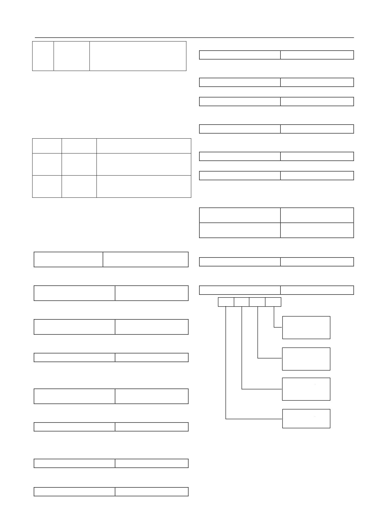
P01.17 servo drive operation status
0000~FFFFH【0000】
-1000.0~1000.0Hz【0.00】
frequency
ThousandsHundreds
Tens
Oncs
Monitor the main setting frequency under ordinary operation
place
place
placs
placs
mode. Non-ordinary operation mode will be displayed as 0.
BIT0: Run/stop
P01.02 Auxiliary given set
-1000.0~1000.0Hz【0.00】
BIT1: Inverse/forward
frequency
BIT2:Zero speed operation
BIT3 : Speed
Monitor auxiliary setting frequency under ordinary operation
mode. Non-ordinary operation mode will be displayed as 0.
BIT0: Reduce speed
P01.03 Setting frequency
-1000.0~1000.0Hz【0.00】
BIT1: Constant speed operation
BIT2: Pre-excitation
Monitor the final frequency through primary and secondary
BIT3 : Tuning
synthesis. The positive value indicates forward; the negative
BIT0: Flow limit
indicates reverse.
BIT1: Dc overvoltage limit
P01.04 Acceleration and
BIT2: Torque limitation
-1000.0~1000.0Hz【0.00】
BIT3: Speed limiter
deceleration frequency instruction
Monitor servo drive output frequency through acceleration and
BIT0: Drive malfunction
deceleration process including frequency direction.
BIT1: Speed control
BIT2: Torque Control
P01.05 Output frequency
-1000.0~1000.0Hz【0.00】
Monitor servo drive output frequency including frequency
Figure 6-2: servo drive run
direction.
LED unit digit BIT0: operation/stop;
When servo drive is in stop status, the BIT0 position shall be 0.
P01.06 output voltage
0~480V【0】
Otherwise it will be 1.
Monitor servo drive output voltage.
LED unit digits BIT1: reverse/forward;
When servo drive forwards, BIT1 position is 0. Otherwise it will
P01.07 output current
0.0~3Ie【0】
be 1.
45
Chapter VI Function Code Details
When meeting condition, other positions may be set as 1.
Note
P01.18 switch input status
000~3FFH【000】
When analog input is current input, the adjusted AI input
range shall be 4~20mA. The corresponding display range
Hundred
Tens
Ones
s place
place
place
shall be 2~10.
BIT0: X1 Terminal state of on and off
P01.26 AO1 output
0.0%~100.0%【0.0】
BIT1: X2 Terminal state of on and off
P01.27 AO2 output
0.0%~100.0%【0.0】
BIT2: X3 Terminal state of on and off
BIT3: X4 Terminal state of on and off
P01.26 and P01.27 show percentage of analog output value to full
scale capacity.
BIT0: X5
Terminal state of on and off
For example: when AO1function setting is: output frequency; the
BIT1: X6
Terminal state of on and off
BIT2: X7
Terminal state of on and off
maximum frequency is 100Hz; actual operation frequency is
BIT3: X8
Terminal state of on and off
50Hz; then P01.26 shall display 50%.
BIT0: FWD
Terminal state of on and off
BIT1: REV
Terminal state of on and off
P01.28 process closed-loop given
-100.0%~100.0%【0.0】
:Reserv
BIT2
:Reserve
P01.29 process closed-loop feedback
-100.0%~100.0%【0.0】
BIT3
e
P01.30 process closed-loop error
-100.0%~100.0%【0.0】
Figure 6-3: Switch input status
P01.31 process closed-loop output
-100.0%~100.0%【0.0】
The figure shows on-off status of 10 terminals, including X1~X8,
P01.28 ~ P01.31 show percentage of P13 group process
FWD, REV. “0” represent the terminal in off status; 1 represents
closed-loop given value, feedback value, error value, output value
the terminal in close status.
to full scale capacity.
P01.19 Switch output status
0~FH【0】
P01.32 rediator 1 temperature
0.0~150.0℃【0.0】
P01.33 rediator 2 temperature
0.0~150.0℃【0.0】
Ones placs
Radiator 1 temperature shows temperature of inverter module.
Different types of inverter modules have different
BIT0:Y1 State of terminal signal
over-temperature protection values.
BIT1: Y2 State of terminal signal
Radiator 2 temperature shows temperature of rectifier module.
BIT2: BR Relay ttracts gathers state
Rectifier bridge temperature below
37kW type shall be not
Relay ttracts gathers state
BIT3: T
inspected.
Temperature display range: 0~150℃; accuracy: 5%
Figure 6-4: Switch output status
Function code P01.19 may display output status of switch
terminal Y1, Y2 and relay BR, T. When output signal is
P01.34~P01.35
Reserved
implemented, the related position of P01.19 will be set as 1.
Reserved function
For example, when signal output only exists in Y1 terminal, the
BIT0 position will be set as 1, the P01.19 display value will be 1.
P01.36 charge cumulative time
0~65535 hours【0】
When signal output only exists in relay T, the P01.19 display
P01.37 operation cumulative time
0~65535 hours【0】
value will be 8.
P01.38 fan operation cumulative time
0~65535hours【0】
P01.36 ~P01.38 shows respectively charge cumulative time,
P01.20 AI1 input
-10.00~10.00V【0.00】
operation cumulative time and fan operation cumulative time of
P01.21 AI2 input
-10.00~10.00V【0.00】
servo drive from factory.
P01.22 AI3 input
-10.00~10.00V【0.00】
P01.20~P01.22 shows analog input signal before adjustment.
P01.39
Reserved
Reserved function.
P01.23 adjusted AI1 input
-10.00~10.00V【0.00】
P01.24 adjusted AI2 input
-10.00~10.00V【0.00】
P01.40 ASR controller output
-300.0%~300.0%【0.0】
P01.25 adjusted AI3 input
-10.00~10.00V【0.00】
Percentage to motor rated torque, it shows ASR controller output.
P01.23~P01.25 shows the adjusted analog input signal through
P01.41 torque given
-300.0%~300.0%【0.0】
increment, deviation.
Percentage to motor rated torque, it shows torque given.
P01.42
Reserved
Reserved function.
46
Chapter VI Function Code Details
P01.43 given high position
0000~FFFFH【0000】
2.The rotational speed adjuster parameter shall be adjusted
P01.44 given low position
0000~FFFFH【0000】
to ensure good static, dynamic control performance. For
setting and adjusting of rotational speed adjuster, see related
P01.45 feedback high position
0000~FFFFH【0000】
description of P07 parameter.
P01.46 feedback low position
0000~FFFFH【0000】
3.When select the vector control mode, one servo drive shall
Monitor given position and feedback position under servo control
drive only one motor. The difference of capacity between
mode.
servo drive and motor shall be not larger. Power degree of
motor is smaller two-degree (one degree larger) than servo
drive. Otherwise the control performance will be lowered; or
P01.47 position deviation pulse
-9999~9999【0】
the control system could not operate in normal.
Monitor position deviation pulse under servo control mode.
4.When select PG vector control or PG V/F control, the P12
group PG encoder parameters shall be set correctly.
5.When select V/F control, the V/F control specific function
P01.48~P01.57
Reserved
code (P06 parameter group) shall be set correctly.
Reserved function.
P02.01motor option
0~1【0】
6.1.3Basic Operation Parameter
(P02 group)
0: motor 1
P02.00 Motor and mode option
0000~1313H【0002】
1: motor 2
Once
ThousandsHundreds Tens
s
place
place
place
Parameters of motor 1 and motor 2 shall response to function code
place
Motor 1
P03 group and P04 group.
Control mode selection
0: NoPG vector control
1:With PG vector control
P02.02 operation command channel option
0~3【0】
2 :No PG V/F control
3 :With PG V/F
contorl
HSD2000 equips with three types of command channels
Motor1
Type selection
0: operation panel operation command channel
0 :Asynchronous motor
1 : synchronous motor
Start and stop by RUN, STOP and JOG keys in operation panel.
Motor2
Control mode selection
1: Terminal operation command channel
0 :No PG vector control
1:WithPG vector control
2:NO PG V/F control
Start and stop by external controlling terminal FWD, REV, JOG
3:With PG V/F control
forward and JOG reverse.
Motor2
Type selection
0 :Asynchronous motor
2: Serial port operation command channel
1 : synchronous motor
Start and stop by serial port.
Figure 6-5: motor and control mode option
3: Reserved
Motor control mode
Note
0: No PG vector (open-loop vector) control
1.Even in operation process, the following methods may
The no speed sensor vector control operation mode may be used
change operation command channel: modify the function code
in field of high-performance general-purpose variable speed drive.
parameter; using external terminal or LOCAL key. It shall be
used carefully.
1: PG vector control
2.When switch the operation command channel to terminal
The speed sensor vector control operation mode may be used for
control, ensure REV/FWD terminal invalid before command
high control performance requirements fields such as precision
channel switching.
speed control, torque control, simple servo control.
HSD2000 servo drive setting frequency may be integrated by
2: No PG V/F control mode
main setting frequency and auxiliary setting frequency. The
It may control voltage/frequency percentage constantly. The speed
P02.08~P02.10, P14.07 are used for define auxiliary frequency.
may be changed. It may be used for field of one servo drive with
Figure 6-6 shows setting frequency forming process by adjusting
multi motors. It may improve current governing system.
main setting frequency and auxiliary setting frequency in
3: PG V/F control mode
percentage.
It may be used for simple speed feedback control, especially for
Main given
Main, auxiliary
f1
f3
Set the frequency ratio
f4
Set
frenquency
given operations
the fields of PG not on motor shaft.
adjustment P02.12: P02.13
frequency
P02.11
P02.03
Note
f2
Auxiliary a given
PG means optical tachometer pulse encoder.
frequency
P02.08
1.When select vector control mode, the motor automatic
tuning mode shall be implemented to obtain correct motor
parameters before the first operation. When the motor
Figure 6-6: setting frequency schematic diagram
automatic tuning process finishes, the tuning motor parameter
will be storage inside of control panel for control operation
P02.03 main setting frequency source
0~5【0】
later.
option
0: digit given 1, operation panel▼,▲adjustment
47
Chapter VI Function Code Details
When servo drive powers up, the function code P02.04 value shall
0V~+10V segments, forward, response to frequency defined in
be as current setting frequency.
P11 group function code.
When servo drive is in operation or stop status, the▼and▲ key of
0V~-10V segments, forward, response to frequency defined in
operation panel shall be used to change current setting frequency
P11 group function code.
of servo drive.
4: Terminal pulse (PULSE) given
1: Digit given 2, terminal UP/DOWN adjustment
Frequency setting shall be defined by terminal pulse frequency.
Under the mode, function code P02.04 value in servo drive
The input shall be X8. Specified refer to P10 group definition.
powers up shall be set as current setting frequency of servo drive.
5: Reserved
By setting external control terminal function, the current setting
Note
frequency shall be implemented in operation or stop status of
servo drive.
Frequency main given mode of 3 and 4 frequency calculation
shall be determined by function code P11.25 ~ P11.41 of
When select the sting mode, the following parameters setting shall
relationship curve. When the main frequency given is analog
be implemented:
or pulse given, positive and negative polarity of output main
1) In parameter P10.00 ~ P10.07, functions of both external
setting frequency shall be determined by analog and pulse
control terminals shall be 13, 14.
value. The value is not related with P02.20 function code. In
reverse, setting frequency positive and negative polarity of
2) According to function code P10.09, P10.10, the value change
other frequency given modes shall be determined by P02.20.
rate of UP/DN terminal in frequency setting.
Select to
Frequency increment
Short as UP terminal
P02.04 main setting frequency
Lower limit frequency~upper
13
define both
instruction UP
below
digital setting
limit frequency【50.00Hz】
terminals in
Frequency decrement
Short as DOWN
14
When main setting frequency cannel is defined as digit given
X1~X8
instruction DOWN
terminal below
(P02.03=0, 1, 2), the function parameter shall be initial setting
frequency of servo drive main setting frequency.
When select digit given-2 mode, the wiring schematic diagram is
shown below:
P02.05 maximum
UPswitch
HSD200
Max (50.00,P02.06) ~1000.0H【50.00Hz】
output frequency
UP
0
P02.06 upper limit
Lower limit frequency~ maximum
terminal
DOW
frequency
outputfrequency【50.00Hz】
N switch
DOWtermina
P02.07 lower limit
N l
0~ upper limit frequency【0.00Hz】
frequency
CO termina
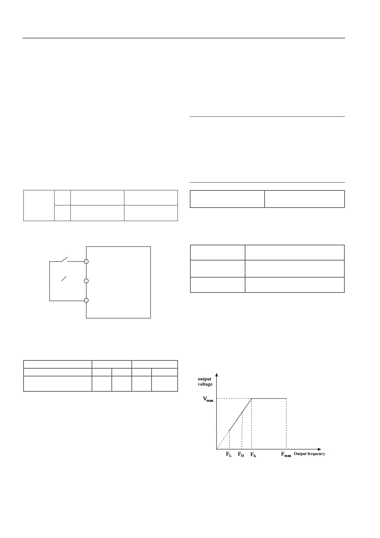
Maximum output frequency is the highest frequency allowed by
M l
servo drive. As Fax of 0:
Upper limit frequency is the highest frequency allowed by user
setting. As FH of 0:
Figure 6-7: Digital setting 2 connection schematic diagram
Lower limit frequency is the lowest frequency allowed by user
Under terminal closes, relationship of two external switch statue
setting. As FL in figure 6-8:
setting and servo drive current setting frequency is as follows:
Fbin 0 represents the basic operation frequency. It is the response
External switch status and servo drive current setting frequency
output frequency minimum value of servo drive in V/F output
UP terminal switch status
Break
Close
mode.
DOWN terminal switch status
Break
Close
Break
Close
servo drive current setting
Decreas
Increas
Keep
Keep
frequency
e
e
2: Digit given 3, serial port communication given
The setting frequency shall be changed by serial port frequency
setting order.
3: AI analog given
Analog given has three separate physical channels: AI1, AI2 and
AI3.
AI is analog signal input channel. When AI inputs as voltage
signal, the voltage input range shall be:
-10V~0V~+10V. For
Figure 6-8: Limit frequency parameter schematic diagram
adjusted analog input signal (-10V~0V~+10V), the following
regulations:
48

Chapter VI Function Code Details
Note
shall be determined by analog or pulse value. It doesn’t matter
with P02.20 function code.
1. Maximum output frequency, upper limit frequency and
2.Main and auxiliary frequency given channel shall be mute
lower limit frequency shall be set carefully as actual controlled
(except the AI channel 0).
motor nameplate parameter and work station demands.
2. Upper limit frequency, lower limit frequency limit range is
P02.09 auxiliary given
invalid to jog JOG operation and motor automatic tuning
0.00~9.99【1.00】
coefficient
operation.
It is only effective to P02.08=4, 5, 7. The analog and pulse given
3.In addition upper limit frequency, lower limit frequency
limit, output frequency of servo drive operation is limited by
value shall be calculated as auxiliary frequency of defined curve.
start frequency, stop DC braking start frequency, jump
Then the P02.09 shall be used for gain calculation.
frequency.
4. Relationships of maximum output frequency, upper limit
P02.10 auxiliary given digital
frequency, and lower limit frequency are shown in figure 6-8.
0.00~1000.0【0.00Hz】
setting
The order shall be noted in setting.
5.Upper and lower limit frequency is used to limit frequency
P02.10 is only effective to P02.08=1~3. It is also initial value of
output to motor frequency value. When the setting frequency
auxiliary setting frequency in the three types.
is higher than upper limit frequency, upper limit frequency
P02.11 main and auxiliary
shall be operated. When setting frequency is lower than
0~6【0】
given calculation
lower limit frequency, lower limit frequency shall be
operated. When setting frequency is lower than start
0: “+”
frequency, the zero frequency shall be operated.
Setting frequency shall be sum of main setting frequency and
6.Under vector control mode, the maximum output frequency
auxiliary setting frequency.
shall be 400Hz.
When the positive and negative polarity integrated frequency is
reverse to main setting frequency polarity, the setting frequency
P02.08 auxiliary setting
shall be zero.
0~7【0】
frequency source option
1: “-”
0: No auxiliary given
Setting frequency shall be difference of main setting frequency
Setting frequency is only made up of main setting frequency.
and auxiliary setting frequency.
Default value of auxiliary setting frequency shall be zero.
When the positive and negative polarity integrated frequency is
1: Digit given 1,operation panel▼and▲ keys adjustment
reverse to main setting frequency polarity, the setting frequency
Auxiliary frequency initial setting value shall be P02.10. It shall
shall be zero.
be adjusted by operation panel▼and ▲keys.
2: “*”
2: Digit given 2,terminal UP/DOWN adjustment
Setting frequency shall be product of main frequency and
Auxiliary frequency initial value shall be set as P02.10. It shall
auxiliary frequency.
be adjusted by terminal UP/DOWN.
When the positive and negative polarity integrated frequency is
Terminal UP/DOWN setting may refer to P10 group function
reverse to main setting frequency polarity, the setting frequency
code.
shall be zero.
3: Digit given 3, serial port communication given
3: MAX (main setting frequency, auxiliary setting frequency)
Auxiliary frequency is given by serial port. The frequency
Setting frequency shall be maximum absolute value between
setting initial value shall be P02.10. The auxiliary setting
main setting frequency and auxiliary setting frequency.
frequency shall be changed by setting command.
When positive and negative polarity of auxiliary setting frequency
4: AI analog given
is reverse to main setting frequency, the setting frequency shall be
Auxiliary frequency setting is given by AI terminal (AI1, AI2
main setting frequency.
and AI3).
4: MIN (main setting frequency, auxiliary setting frequency)
5: Terminal pulse (PULSE) given
Setting frequency shall be minimum absolute value between main
Auxiliary frequency setting is determined by terminal pulse
setting frequency and auxiliary setting frequency.
frequency with only X8 input. Specific refer to P10 group of
When the positive and negative polarity integrated frequency is
function code definitions.
reverse to main setting frequency polarity, the setting frequency
6: Reserved
shall be zero.
7、 Process closed-loop output
5: Sqrt
(main setting frequency)
+ Sqrt
(auxiliary setting
The process closed-loop output shall be given as auxiliary.
frequency)
The setting frequency shall be sum of square root after absolute
Note
value between main setting frequency and auxiliary setting.
1.When auxiliary frequency is given by modes of 4 and 5,
positive and negative polarity of output auxiliary frequency
49
Chapter VI Function Code Details
When auxiliary setting frequency and main setting frequency
P02.19*P02.16
polarity is reverse, the auxiliary frequency shall be cleared zero.
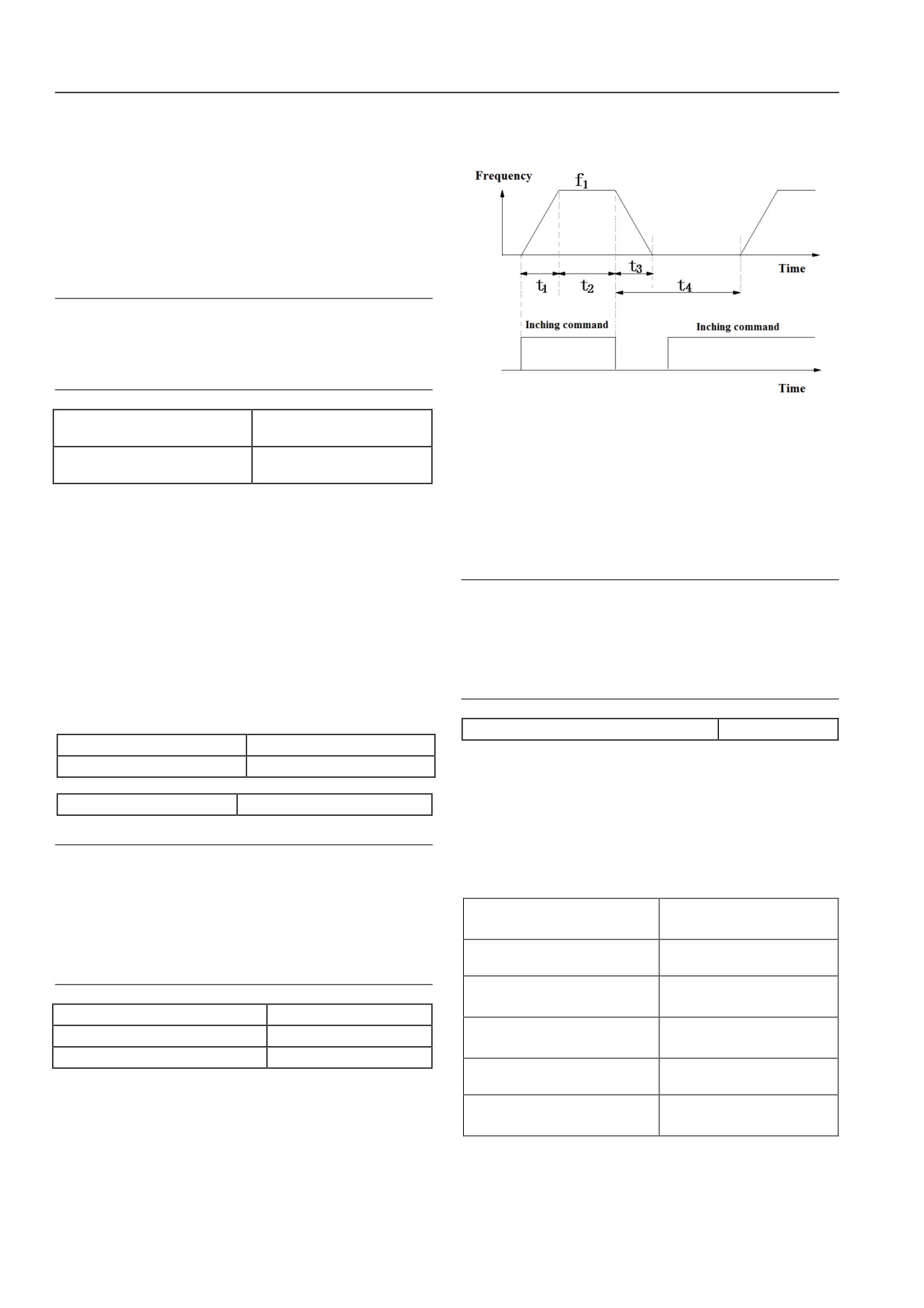
t1=
P02.05
Setting frequency shall be square root of main setting frequency.
6: Sqrt (main setting frequency + auxiliary setting frequency)
The setting frequency shall be sum of square root after absolute
value between main setting frequency and auxiliary setting.
When main setting frequency and auxiliary setting frequency sum
polarity are reverse to main setting frequency polarity, the setting
frequency shall be zero.
Note
When the P02.08 option 0 auxiliary given is invalid, the main
and auxiliary calculation principle P02.11 shall be invalid.
The setting frequency is determined by main setting
frequency.
Figure 6-9: jog parameter
P02.12 setting frequency
0~2【0】
percentage adjustment option
Jog interval time (P02.19) shall be: from previous jog command
P02.13 setting frequency
canceling to the next jog command taking effect.
0.0%~200.0%【100.0%】
percentage adjustment coefficient
During interval time, the jog command will not make servo drive
The function determines the adjustment mode of setting frequency
operate. The servo drive shall be operated as zero frequency of no
(integrated frequency of main setting frequency and auxiliary
output. When the jog command exists, the jog command will be
setting frequency).
started to implement after interval. Jog command after jog interval
0: No action
shall be implemented immediately.
The main and auxiliary given integrated setting frequency shall be
Note
not adjusted. It is P4=P3.
1.Jog operation starting and stop shall follow start mode 0
1: Relative maximum output frequency P02.05 adjustment
and stop mode
0. Time unit of jog acceleration and
setting frequency P4=P3+P02.05× (P02.13-100%)
deceleration shall be second.
2: Relative current frequency adjustment
2.Operation panel, control terminal and serial port shall
implement jog control.
setting frequency P4=P3+P3× (P02.13-100%) =P3×P02.13
P02.20 operation direction setting
0、1【0】
P02.14 acceleration time 1
0.0~3600.0s (min) 【6.0s】
The function is applicable to operation panel running command
P02.15 deceleration time 1
0.0~3600.0s (min) 【6.0s】
channel and serial port running command channel. It is not
effective to terminal operation command channel.
P02.16 Jog frequency
0.01~50.00Hz【5.00Hz】
0: Forward
Set frequency of jog operation.
1: Reverse
Note
Under control panel condition, the jog operation may be
6.1.4 Motor 1 parameter (P03 group)
achieved by JOG on panel. Press the JOG key to operate.
Loss the JOG key, it will implement stop operation of stop
P03.00 asynchronous motor rated
0.4~999.9kW【model
mode. Under terminal control condition, the terminal
power
determination】
function shall be set for jog operation by jog forward
P03.01 asynchronous motor rated
terminal or jog reverse terminal. In addition, the jog
0~P97.04
frequency
operation may be controlled by communication mode.
P03.02 asynchronous motor rated
0.1~999.9A【model
current
determination】
P02.17 Jog acceleration time
0.1~60.0s【6.0】
P03.03 asynchronous motor rated
1.00~100.00Hz【model
P02.18 Jog deceleration time
0.1~60.0s【6.0】
frequency
determination】
P02.19 Jog interval
0.0~100.0s【0.0】
P03.04 asynchronous motor
0~60000RPM【1440RPM】
As shown in Figure 6-9: t1, t3 are actual operation jog acceleration
rated rotational speed
and deceleration time; t2 shall be jog time; t4 shall be jog interval
P03.05 asynchronous motor
0.001~1.000【model
time (P02.19); P1 shall be jog operation frequency (P02.16).
power factor
determination】
Actual operation jog acceleration time t1 shall be determined by
Set controlled asynchronous motor parameter.
the following formula. Similarly, actual operation jog
For control performance, the P03.00~P03.04 value shall be set as
deceleration time t3 shall be also determined by the formula.
asynchronous motor nameplate parameters.
50
Chapter VI Function Code Details
P03.05 is asynchronous motor power factor. The value will be
V: rated frequency;
updated automatically after normal operation tuning. User may
I: asynchronous motor rated current
select to modify P03.05 automatically. The following two
When the asynchronous motor parameters have been known, the
conditions may be modified manually: after all tuning finishes; no
calculation value shall be written as formula above P03.06~
tuning.
P03.09. P03.10 is asynchronous motor empty load current. User
Note
may input empty load value directly.
Asynchronous motor and servo drive power class shall meet 等
When implement self tuning of motor parameter, the P03.06~
the configuration. In general, two-class smaller or one class
P03.10 setting values will be changed after the tuning finishes.
larger of servo drive is allowed. Control performance shall
After modify the asynchronous motor power P03.00, servo drive
not be ensured when exceeding the range.
will set P03.02 ~ P03.10 parameter as related power
asynchronous motor default parameter (P03.01 is asynchronous
P03.06 asynchronous motor
0.00~50.00%【model
stator resistance %R1
determination】
motor rated frequency value. It is not in asynchronous motor
default parameter. It shall be set by users as nameplate).
P03.07 asynchronous motor
0.00~50.00%【model
leakage inductance %X
determination】
P03.08 asynchronous motor
0.00~50.00%【model
P03.11 asynchronous motor
0~3【0】
rotor resistance %R2
determination】
parameter self tuning
P03.09 asynchronous motor
0.0~2000.0%【model
0: No action
mutual inductance %Xm
determination】
1: Action (asynchronous motor static)
P03.10 asynchronous motor
0.1~999.9A【model
Before self tuning, the nameplate parameters (P03.00~P03.04) of
load current
determination】
controlled asynchronous motor shall be entered.
Specific meanings of motor parameter above may refer to figure
When in static tuning, the motor is in state of static. The
6-10.
asynchronous motor tutor resistance
( % R1), related rated
frequency leakage inductance (%X), rotor resistance (%R2) shall
R1
1
R2
jX
21
X 1
be measured automatically. The measured parameters shall be
written into P03.06, P03.07 and P03.08 automatically.
I
1
I 2
2: Action (asynchronous motor rotates)
1-S
U 1
S R2
Before self tuning, the nameplate parameters (P03.00~P03.04) of
I 0
controlled asynchronous motor shall be entered.
Xm
When in static tuning, the motor is in state of static. The
asynchronous motor tutor resistance
( % R1), related rated
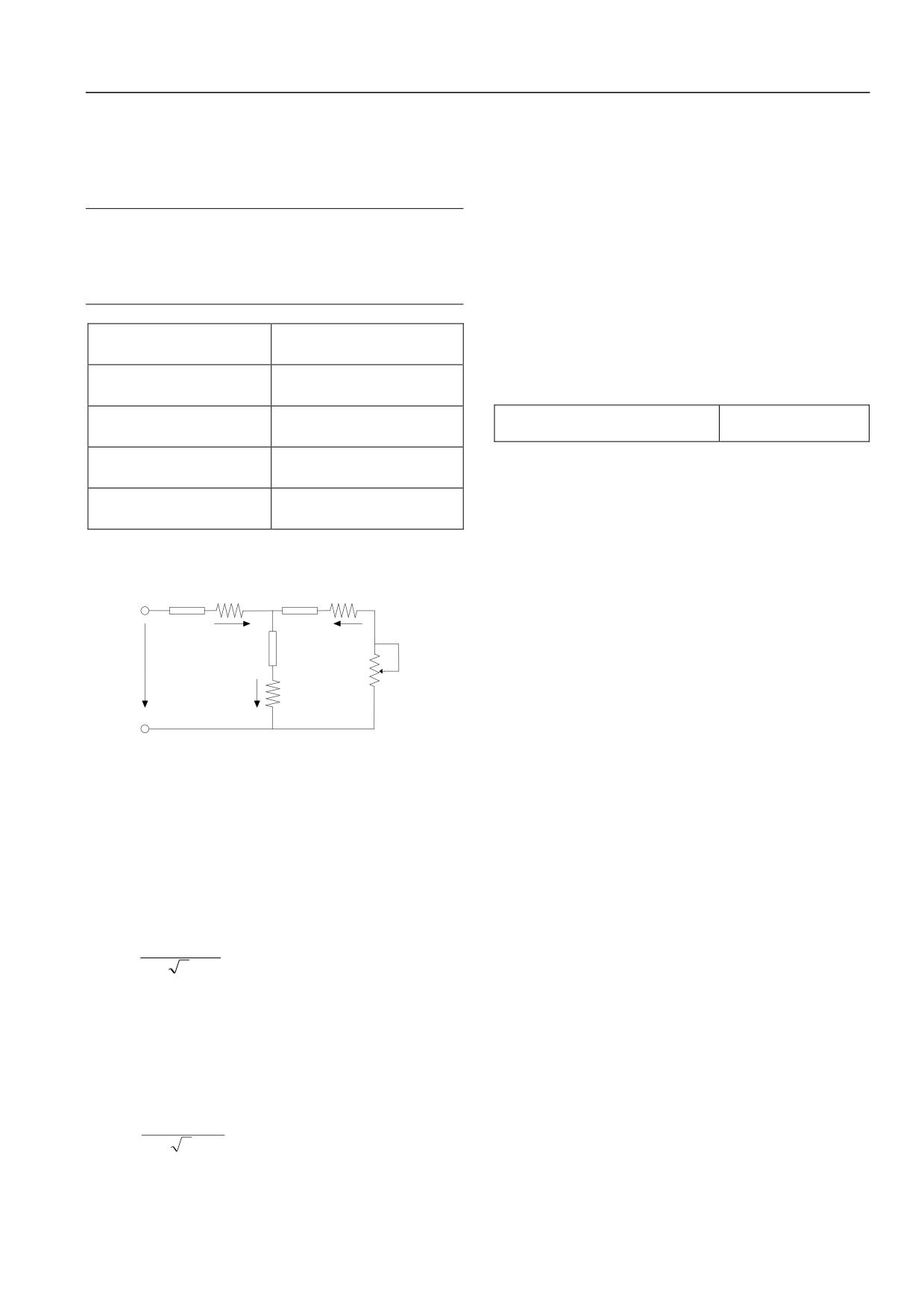
Figure 6-10: Asynchronous Motor Static Equivalent Circuit Figure
frequency leakage inductance (%X), rotor resistance (%R2) shall
In the 0, the R1, X11, R2, X21, Xm, Io represents respectively: stator
be measured automatically. Then the asynchronous motor is in
resistance, the stator leakage inductance, rotor resistance, rotor
rotation status, the motor mutual inductance (%Xm) and empty
leakage inductance, mutual inductance, no-load current. The
load current (Io) shall be measured automatically. The measured
function code P03.07 shall be sum of stator and rotor leakage
parameters will be written into P03.06, P03.07, P03.08, P03.09
inductance.
and P03.10 automatically. The P03.05 will be updated after rotate
Above P03.06~P03.09 are percentages of asynchronous motor
tuning.
parameters. The formula shall be:
After self tuning, the P03.11 setting value shall be set as
0
1) Resistor (stator resistance or rotor resistance) formula:
automatically.
R
Self tuning procedures:
%
R
100
%
V
/(
3
I
)
1) It is suggested for users to set P06.07 (motor 1torque lifting) as
R: rotor resistance actual value of stator resistance converted to
0.
the stator side;
2) Set function code parameter “P03.00 rated power”, “P03.01
V: rated frequency;
rated frequency”,
“P03.02 rated current”,
“P03.03 rated
I: asynchronous motor rated current
frequency” and “P03.04 rated rotational speed”.
2) Inductive reactance (leakage inductance or mutual inductance)
3) Set P02.06 (upper limit frequency). P02.06 setting value shall
formula:
be not lower than rated frequency。
X
4) When select P03.11 as 2, remove the motor shaft from loading
%
X
10
%
0
V/(
3I)
and ensure its safety. The motor shall not rotate tuning with
(2)
loading.
X: sum (inverted to the stator side) or mutual inductance of basic
5) Set P03.11 as 1 or 2. First press DATA/ENTER key, then press
frequency stator and rotor
the RUN key for self tuning.
51
Chapter VI Function Code Details
6) When the operation indicator of operation panel is off, the self
P03.13 synchronous motors
0.4~999.9kW【model
tuning has been finished.
rated power
determination】
3: Reserved
P03.14 synchronous motors
0~P97.04
rated frequency
Note
P03.15 synchronous motors
0.1~999.9A【model
1.When set P03.11 as 2, the overvoltage or over current fault
rated current
determination】
may be processed by increasing acceleration and deceleration
P03.16 synchronous motors
1.00~100.00Hz【model
time (P02.14 and P02.15).
rated frequency
determination】
2.When select P03.11 as 2, remove the motor shaft from
P03.17 synchronous motors
1~40【2】
loading and ensure its safety. The motor shall not rotate
pole pairs
tuning with loading.
P03.18 synchronous motors
0~60000RPM【1500RPM】
rated rotational speed
3.Before start self tuning, the motor shall be ensured
P03.19 synchronous motors
0.00~50.00%【model
shutdown. Otherwise the self tuning shall not operate
stator resistance
determination】
normally.
P03.20 synchronous motors
0.0~999.9mH【model
4.In conditions of not convenient to rotate or lower motor
control performance requirements (such as motor could be
direct axis inductance
determination】
not removed from loading), the static tuning or no tuning may
P03.21 synchronous
0.0~999.9mH【model
be implemented. When the tuning doesn’t implement, the
motors cross-axis inductance
determination】
motor nameplate parameter shall be entered.
P03.22 synchronous
5.When the self tuning couldn’t be implemented, the motor
0~1000【150】
motors back-EMF constant
parameter has been known by user. The user shall enter
Setting controlled synchronous motors parameter.
correct motor nameplate parameter (P03.00~P03.04). Then
the motor parameter calculation value shall be entered as
For controlling performance, the P03.13~P03.22 value shall be
resistor and inductive reactance formula above (P03.06~
set as nameplate parameter of synchronous motors.
P03.10). The parameters shall be set correctly.
Note
6.When the self tuning is not success, report E024 fault;
Synchronous motors and servo drive power degree shall be
7.When the temperature is higher in motor operation, the
matched. In general, it shall be two-class lower or one class
tuning shall be implemented as hot status. The stator
higher than servo drive. Exceeding the range shall not ensure
resistance and rotor resistance parameter shall be increased to
the control performance.
optimize the control performance.
P03.23 synchronous motors
P03.12 asynchronous motor
0~1【0】
position identification
overload protection coefficient
20.0%~110.0%【100.0%】
The function default value is 0. Press RUN key when 0 changes 1.
setting
Synchronous motors will mark the position. After identification,
For overload protection of different models loading motor, the
the P03.23 may recover to 0 automatically.
maximum value of allowed output current in servo drive shall be
P03.24 synchronous motors identify
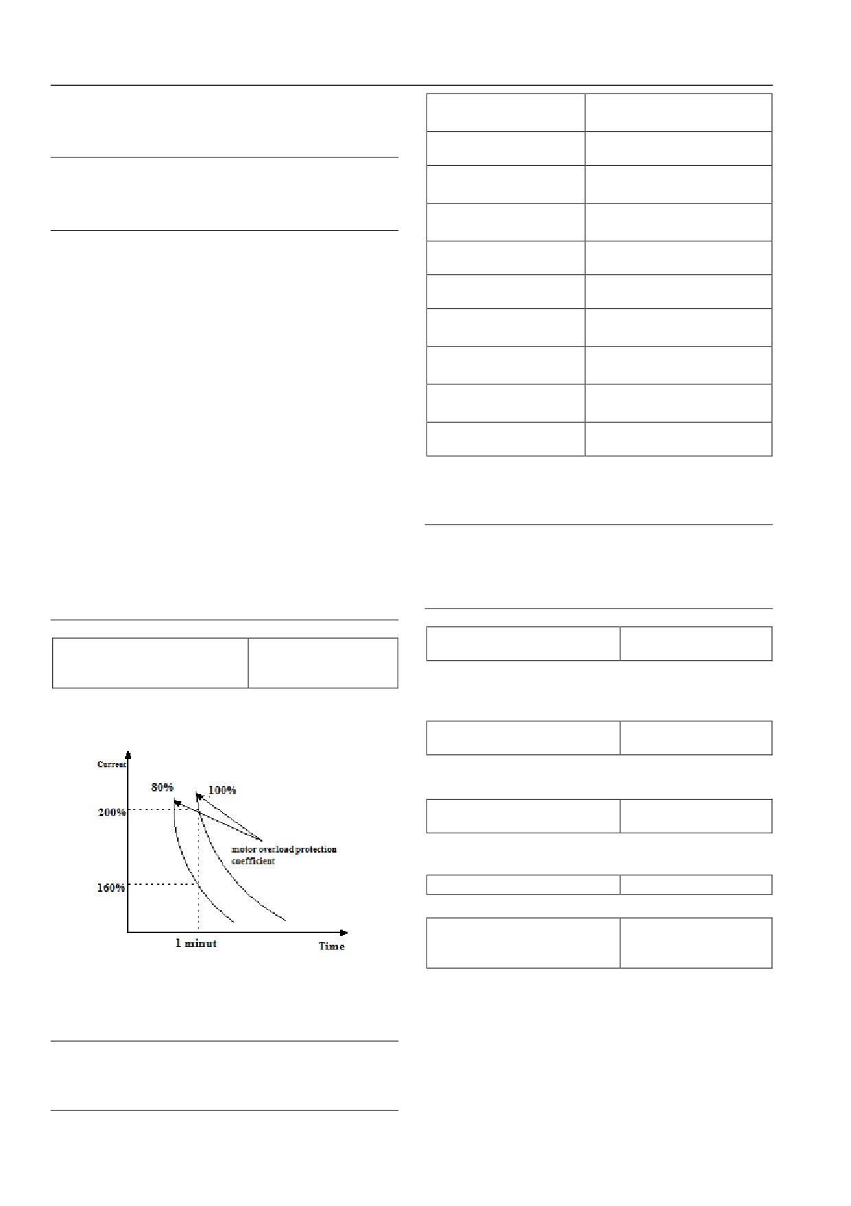
adjusted. As shown in figure 6-11:
0~30【10】
current
The function code shows synchronous motors identification
current result. The rated current range shall be 0~30%.
P03.25 synchronous motors initial
0~FFFFH【0】
angle
The function code shows synchronous motors initial angle for
control calculation.
P03.26 Z pulse initial angle
0~FFFFH【0】
The function code shows Z pulse initial angle.
P03.27 synchronous motors
overload protection coefficient
20.0%~110.0%【100.0%】
setting
Figure 6-11: motor overload protection coefficient setting
For overload protection of different models loading motor, the
The value may be set as requirements of users. In the similar
maximum value of allowed output current in servo drive shall be
condition, the P03.12 value shall be set smaller in motor overload
adjusted. As shown in figure 6-11:
faster protection. In reverse, it shall be set larger.
The value may be set as requirements of users. In the similar
Note
condition, the P03.27 value shall be set smaller in motor overload
When rated current of loading motor and servo drive is not
faster protection. In reverse, it shall be set larger.
the same, the motor overload protection may be achieved by
setting P03.12 function code parameter value.
52

Chapter VI Function Code Details
6.1.5 Motor 2 parameter
(P04 group)
frequency value. It is not in synchronous motor default
parameter range. It shall be set as nameplate by user. ).
P04.00 asynchronous
0.4~999.9kW【model
motor rated power
determination】
P04.11 asynchronous motor
P04.01 asynchronous
0~servo drive rated frequency
0~3【0】
parameter self tuning
motor rated frequency
(P97.04)
0: No action
P04.02 asynchronous
0.1~999.9A【model determination】
1: action (asynchronous motor static)
motor rated current
P04.03 asynchronous
1.00~100.00Hz【model
Before implement the self tuning, the nameplate parameter of
motor rated frequency
determination】
controllers asynchronous motor shall be entered
(P04.00 ~
P04.04 asynchronous motor
P04.04).
0~60000RPM【1440RPM】
rated rotational speed
When in static tuning, the motor is in state of static. The
P04.05 asynchronous motor
0.001~1.00【model determination】
asynchronous motor tutor resistance
( % R1), related rated
power factor
frequency leakage inductance (%X), rotor resistance (%R2) shall
Set the controlled asynchronous motor parameter.
be measured automatically. The measured parameters shall be
For controlling performance, the P04.00~P04.04 value shall be
written into P04.06, P04.07 and P04.08 automatically.
set as nameplate parameter of synchronous motors.
2: Action (asynchronous motor rotates)
P04.05 is asynchronous motor power factor. The value will be
Before self tuning, the nameplate parameters (P04.00~P04.04) of
updated automatically after normal operation tuning. User may
controlled asynchronous motor shall be entered.
select to modify P04.05 automatically. The following two
When in static tuning, the motor is in state of static. The
conditions may be modified manually: after all tuning finishes; no
tuning.
asynchronous motor tutor resistance
( % R1), related rated
frequency leakage inductance (%X), rotor resistance (%R2) shall
Note
be measured automatically. Then the asynchronous motor is in
Synchronous motors and servo drive power degree shall be
rotation status, the motor mutual inductance (%Xm) and empty
matched. In general, it shall be two-class lower or one class
higher than servo drive. Exceeding the range shall not ensure
load current (Io) shall be measured automatically. The measured
the control performance.
parameters will be written into P04.06, P04.07, P04.08, P04.09
and P04.10 automatically. The P04.05 will be updated after rotate
tuning.
P04.06 asynchronous motor
0.00~50.00%【model
After self tuning, the P04.11 setting value shall be set as
0
stator resistance %R1
determination】
automatically.
P04.07 asynchronous motor
0.00~50.00%【model
3: Reserved
leakage inductance %X
determination】
Self tuning procedure:
P04.08 asynchronous motor
0.00~50.00%【model
1) Set the P06.19 torque as 00.0 (if user could not enter P06 group,
rotor resistance %R2
determination】
the function code parameter value of P00.06 shall be modified
P04.09 asynchronous motor
0.0~2000.0%【model
to0200. Press the DATA/ENTER key, then implement function
mutual inductance %Xm
determination】
code operation. The P06 function code group may be entered.)
P04.10 asynchronous motor
0.1~999.9A【model
2) Set function code parameter
“P04.00 rated power”,
empty load current
determination】
“P04.01rated frequency”,
“P04.02rated current” and
“P04.03
Specific meaning of above motor parameter may refer to figure
rated frequency”.
6-11.
3) Set P02.06 (upper limit frequency),P02.06 setting value shall
Function code P04.07 is sum of stator, stator leakage inductance.
be not lower than rated frequency.
Above P04.06~P04.09 are percentage of asynchronous motor
4) When select P04.11 as 2, set acceleration time (P02.14) and
parameter. The calculation formula is shown in formula (1) and
deceleration time
(P02.15). Remove the motor shaft from
(2).
loading and ensure its safety.
When the asynchronous motor parameter has been given, the
5) When set P04.11 as 1 or 2, press the DATA/ENTER. The self
P04.06~P04.09 shall be written into by formula above. The
tuning will be started when press RUN key.
。
P04.10 is asynchronous motor empty load current. The user may
6) When indicator on operation panel is off, the self tuning is
enter empty load current value directly.
finished.
When implement the motor parameter self tuning, the P04.06~
P04.10 setting values will be updated after tuning.
Note
After changing asynchronous motor power P04.00, servo drive
1.When select P04.11 as 2, when overvoltage or over current
will set P04.02~P04.10 parameter as related power asynchronous
fault happens in self tuning, the acceleration and deceleration
shall be increased.
motor default parameter (P04.01 is asynchronous motor rated
53

Chapter VI Function Code Details
2.When set the P04.11 as 2 in rotate tuning. The motor shall
P04.22 synchronous motors
0~1000【150】
remove the loading. The motor shall not rotate tuning with
back-EMF constant
loading.
Set controlled synchronous motors parameter.
3.Before start self tuning, the motor shall be ensured
For control performance, the P04.13~P04.22 values shall be set
shutdown. Otherwise the self tuning shall not operate
as nameplate parameter of synchronous motors.
normally.
4.N conditions of not convenient to rotate or lower motor
Note
control performance requirements (such as motor could be
Synchronous motors and servo drive power degree shall be
not removed from loading), the static tuning or no tuning may
matched. In general, it shall be two-class lower or one class
be implemented. When the tuning does not implement, the
higher than servo drive. Exceeding the range shall not ensure
motor nameplate parameter shall be entered
(P04.00 ~
the control performance.
P04.04).
5.When the self tuning couldn’t be implemented, the motor
P04.23 synchronous motors
0~1【0】
parameter has been known by user. The user shall enter
position identification
correct motor nameplate parameter (P04.00~P04.04). Then
The function default value is 0. Press RUN key when 0 changes 1.
the motor parameter calculation value shall be entered as
Synchronous motors will mark the position. After identification,
resistor and inductive reactance formula above (P04.06~
the P04.23 may recover to 0 automatically.
P04.10). The parameters shall be set correctly.
P04.24 synchronous motors
6.When the self tuning is not success, report E024 fault;
0~30【10】
identification current
7. When the temperature is higher in motor operation, the
The function code shows synchronous motors identification
tuning shall be implemented as hot status. The stator
current result. The rated current range shall be 0~30%.
resistance and rotor resistance parameter shall be increased to
optimize the control performance.
P04.25 synchronous motors
0~FFFFH【0】
initial angle
P04.12 asynchronous motor
The function code shows synchronous motors initial angle for
overload protection coefficient
20.0%~110.0%【100.0%】
control calculation.
setting
P04.26 Z pulse initial angle
0~FFFFH【0】
For effective overload protection to loading motors in different
The function code shows Z pulse initial angle.
types, the servo allowed output current maximum value shall be
P04.27 synchronous motors
adjusted. As shown in figure 6-11.
overload protection coefficient
20.0%~110.0%【100.0%】
The value may be set as requirements of users. In the similar
setting
condition, the P04.12 value shall be set smaller in motor overload
For overload protection of different models loading motor, the
faster protection. In reverse, it shall be set larger.
maximum value of allowed output current in servo drive shall be
Note
adjusted. As shown in figure 6-11:
When rated current of loading motor and servo drive is not
The value may be set as requirements of users. In the similar
the same, the motor overload protection may be achieved by
condition, the P04.27 value shall be set smaller in motor overload
setting P04.12 function code parameter value.
faster protection. In reverse, it shall be set larger.
P04.28 motor 2 PI parameter
0~1【0】
option
P04.13 synchronous motors
0.4~999.9kW【model
The function code shows parameter option function code of PI
rated power
determination】
adjuster in motor 2.
P04.14 synchronous motors
0~P97.04
rated frequency
0: it is the same option with PI adjuster of motor 1.
P04.15 synchronous motors
0.1~999.9A【model
1: it takes P04.29~P04.32 function code value.
rated current
determination】
P04.16 synchronous motors
1.00~100.00Hz【model
P04.29 motor 2 ASR-P
0.1~200.0【20.0】
rated frequency
determination】
P04.30 motor 2 ASR-I
0.010~1.000s【0.200s】
P04.17 synchronous motors
1~40【2】
P04.29 and P04.30 function codes shall be P and I coefficient of
pole pairs
motor 2 ASR.
P04.18 synchronous motors
0~60000RPM【1500RPM】
rated rotational speed
P04.19 synchronous motors
0.00~50.00%【model
P04.31 motor 2 ACR-P
1~5000【1000】
stator resistance
determination】
P04.32 motor 2 ACR-I
0.5~100.0ms【8.0ms】
P04.20 synchronous motors
0.0~999.9mH【model
P04.30 and P04.31 function codes shall be P and I coefficient of
direct axis inductance
determination】
motor 2 ACR.
P04.21 synchronous motors
0.0~999.9mH【model
cross-axis inductance
determination】
P04.33 motor 2 encoder option
0~1【1】
54
Chapter VI Function Code Details
The function code shall be encoder of select motor 2.
0: select local encoder
1: select expansion encoder
When P04.33 selects 1, the HSD2000 specified PG expansion
card shall be configured.
6.1.6Start and Stop Parameter
(P05 group)
P05.00 Starting mode
0, 1, 2【0】
0: start from start frequency
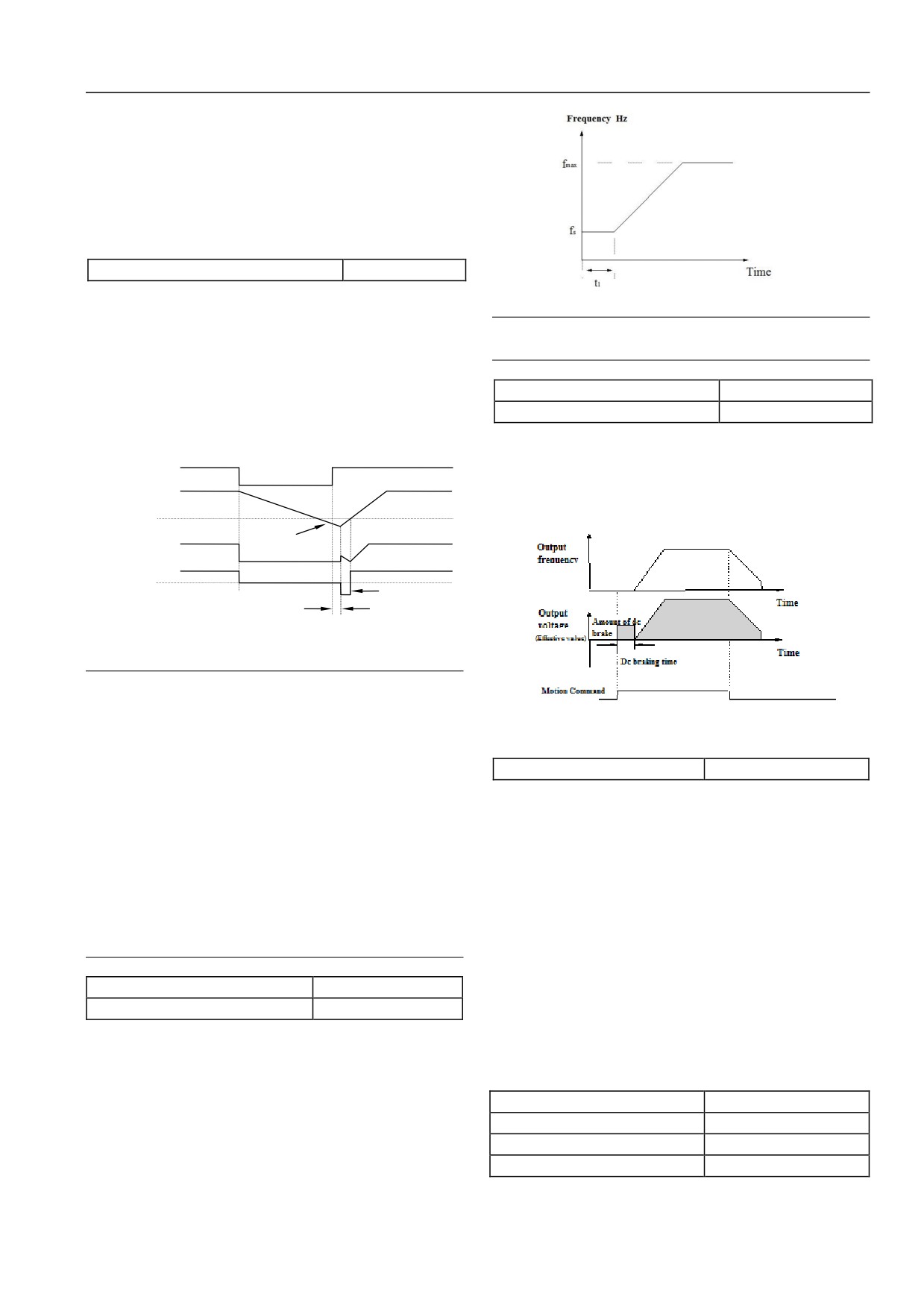
Figure 6-13: start frequency and start schematic diagram
The starting shall be implemented as setting start frequency
Note
(P05.01) and keeping time (P05.02).
Start frequency is not limited by lower limit frequency.
1: Brake and star
Fisted DC brake (refer to P05.03, P05.04), then start as 0 mode.
P05.03 start DC brake current
0.0~100.0%【0.0%】
2. Rotational speed tracing and start
P05.04 start DC brake time
0.00~30.00s【0.00s】
Trace the rotational speed and direction of motor. The rotate motor
P05.03, P05.04 may be effective in “first braking then starting”
starting shall be smooth. As shown in figure 6-12:
mode (P05.00=1). As shown in figure 6-14:
Power
Break
Start DC brake current is percentage relative to servo drive rated
Motor
Close
Close
speed
current. When start DC brake time is 0.0s, there is no DC braking
0
process.
Servo driver
Opposite direction
output
idling
frequency
Forward
Servo drive
Reverse
running
direction
Detection motor
Speed and direction
Figure 6-12: rotational speed track startup schematic diagram
Note
1. Start mode is applicable for small inertia load of forward
and reverse in motor of servo drive stop status. The larger
large inertia load of high speed delivery shall be not
Figure 6-14: start 1 indication
applicable for start mode 1.
P05.05 stop mode
0, 1, 2【0】
2. Start-2 mode is applicable for momentary power outage
0: Deceleration stop
startup for large inertia load of forward and reverse in motor
of servo drive stop status.
When the servo drive receives the stop command, the output
3. Start performance of start mode-2 is related with motor
frequency shall be reduced as deceleration time. Stop shall be
parameter. The parameters related with P03 or P04 group
implemented after the frequency is 0.
shall be set correctly.
1: Freewheel
4.When select start mode 2, the V/F curve shall be straight
After receiving the stop command, servo drive shall stop output
line.
immediately. The loading shall stop as mechanical inertia.
。
5.When driving synchronous motors, the start mode shall be
0.
2: Deceleration stop+DC brake
When the servo drive receives the stop command, the output
P05.01 start frequency
0.00~60.00Hz【0.00Hz】
frequency shall be reduced as deceleration time. When reach
P05.02 start frequency keep time
0.00~10.00s【0.00s】
initial frequency of stop brake, the DC brake shall be started.
Start frequency represents the initial frequency of servo drive
Stop DC brake related function may refer to P05.06~P05.09
starts, such as fS in figure 6-13. The start frequency keep time
definitions:
represents keep operation time for servo drive in start process.
Such as t1 in figure 6-13:
P05.06 Stop DC brake start frequency
0.00~60.00Hz【0.00Hz】
P05.07 Stop DC brake interval time
0.00~10.00s【0.00s】
P05.08 Stop DC brake current
0.0~100.0%【0.0%】
P05.09 Stop DC brake time
0.00~30.00s【0.00s】
55
Chapter VI Function Code Details
Stop brake interval time: during deceleration stop, from operation
Table 6-1 for the various combinations of conditions, after
frequency reaches the brake initial frequency (P05.06) time, to
power up operation when servo drive is in 0: enter standby mode;
time of start adding DC brake values.
1: start automatically. No: power up time without run command;
No output is allowed in stop brake interval time. The time setting
has: power up time has run command.
may prevent over current in brake starting for larger power motor.
Note
Stop DC brake current setting is percentage to servo driver acted
1.When stopped from operation panel, serial port, terminal
current. When the stop brake time is 0.0s, there is no DC brake
controlled by a three-wire, 2 for pulse-type command mode,
process.
power up time without running the command.
2.The stop command shall be priority.
3.Re-start when power outage valid, if not completely
run-down and re-power up (i.e., servo drive LED display
Proof process), then re-start operation in accordance with
rotational speed tracking mode automatically start; If full
power-down (i.e. after the operation panel LED is completely
off) re-power up, then re-start the way P05.00 accordance
start is set up start.
P05.12 anti-reverse option
0、1【0】
0: allow reverse
1: Not allow reverse
Note
The function is effective to command channels.
(Operation
panel operation command channel, terminal operation
command channel and serial port operation command
channel).
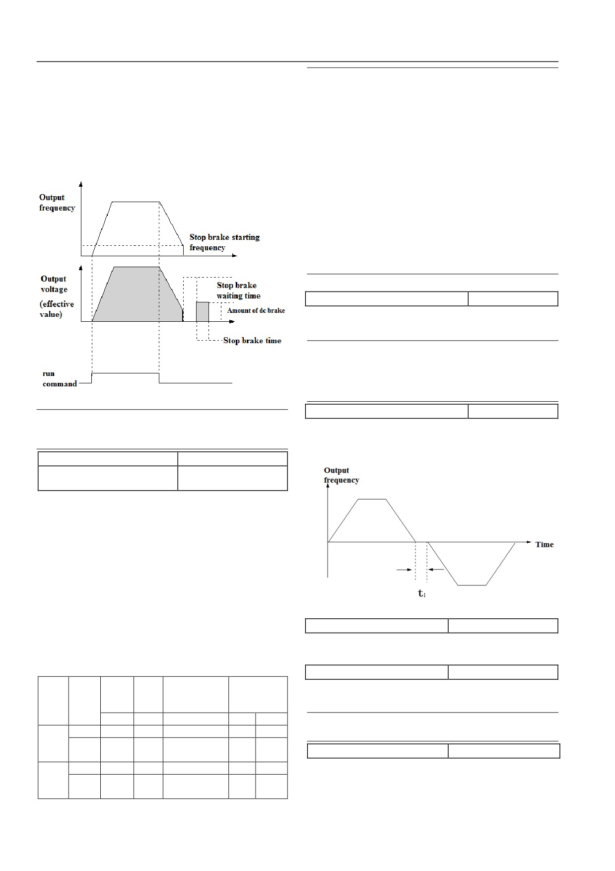
Figure 6-15: deceleration stop +DC brake schematic diagram
P05.13 forward-reverse dead time
0~3600s【0.0s】
Note
servo drive forward run by the transition to the reverse
Percentage of stop brake current (P05.08) to relative servo
operation, or the transition from forward to reverse operation
drive rated current.
during the operation, the output transition time waiting at zero
P05.10 Restart after power fault
0、1【0】
frequency,as
t1
shown
in
figure
6-16.
P05.11 Wating time for restart after
0.0~10.0s【0.0s】
power fault
After this function to achieve servo drive is powered down, when
then power up, under different operating command channel, servo
drive shall automatically start running and interval time before the
automatic operation.
The P05.10 shall be set as 0. The servo drive will not operate
automatically after the power outage powers up.
P05.10 to
1 when the power outage after power up, if the
conditions of the servo drive to meet the start waiting
P05.11-defined time, automatically.
Figure 6-16: Normal/adverse area time
The function code is set, the power-down time running, power up
P05.14 reversible switching mode
0、1【0】
state control commands moment servo drive joint decision
0: Zero-frequency switching
whether to run automatically after power up, see table 6-1.
1: over start frequency switching
Table 6-1: power outage and then start condition feature
P05.15 stop speed
0.00~150.00Hz【0.10Hz】
Status
Operati
Serial
Terminal
Terminal
When setting the speed detection value stop detection methods
P05.10
before
on
port
three-wire 1, 2
two-wire 1, 2
see function code P05.16.
setting
power
panel
down
No
No
No
No
No
Note
Stop
0
0
0
0
0
The speed stopping is only valid in P05.05=0 mode.
0
Operati
0
0
0
0
0
P05.16 stop speed detection method
0, 1【0】
on
Stop
0
0
0
0
1
0: speed setting value
1
Operati
Only the mode may be used in V/F control mode.
1
1
1
0
1
on
1: Speed inspection value
56
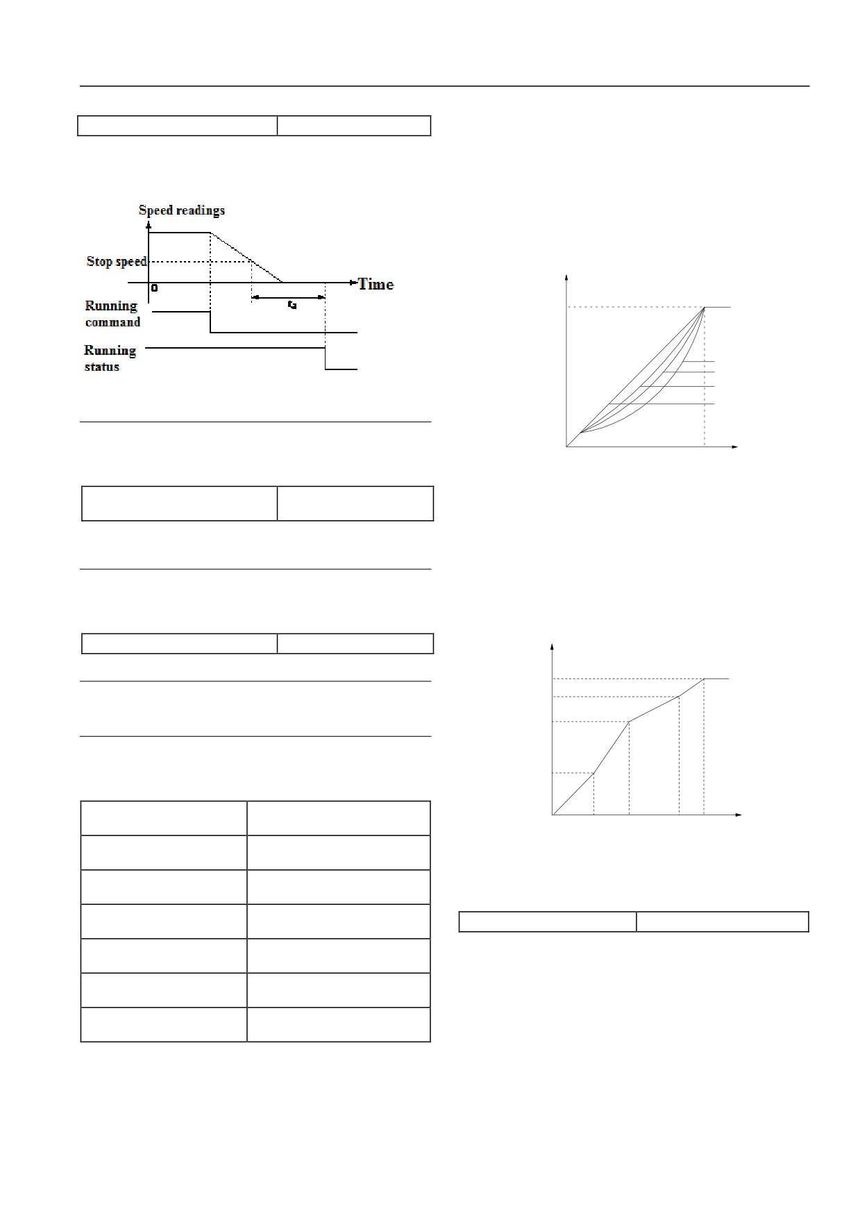
Chapter VI Function Code Details
z
When P06.00 Option 1, is 2.0 times the power down torque
P05.17 stop latency
0~10.00s【0.05s】
characteristics; such as in Figure6-18 curve.
z
When P06.00 select 2, 1.7 power down torque characteristics;
During motor deceleration, when the motor speed reaches the
such as in Figure6-18 curve 2.
stop speed, motor stop running after the delay time. As shown in
Figure6-17, td represents stop speed delay time.
z
When P06.00 Option 3, is 1.2 times the power down torque
characteristics; such as in Figure6-18 curve 3.
These curves apply to variable torque fan and pump loads, the
user can adjust the load characteristics to achieve optimal energy
savings.
Output
Voltage V
Vmax
1
2
3
Figure 6-17: Stop speed test
0
Note
Stop speed delay time for V / F control mode is invalid and must
0
Output
Fb
be stopped when the speed of detection speed detection value
frequency Hz
Vmax: Maximum output voltage
(P05.16 = 1) is valid.
Fb: The basic operating frequency P06.09
P05.18 energy consumption brake
0, 1【0】
option
Figure 6-18: De-torque curve
0: no use energy consumption brake
When P06.00 select 0, users can customize by P06.01 ~ P06.06 V / F
1: use energy consumption brake
curve, as shown in Figure6-19. By increasing (V1, F1), (V2, F2), (V3, F3)
three points define a line V
/ F curve to apply to specific load
Note
characteristics.
Be sure to use according to the actual situation, this feature is set
The factory default user-defined V / F is a straight line, curve, see
correctly parameter. Otherwise it will affect the control
characteristics.
Figure6-18 curve 0.
P05.19 brake utilization
0.0~100.0%【80.0%】
Voltage%
It is effective to braking unit built-in model.
100%
Note
V3
The function setting shall consider resistance value and power
V2
of braking resistor.
V1
6.1.7V/F Control Parameter
(P06 group)
P06.00 motor 1V/F curve
0~3【0】
setting
F1
F2
F3
Fb
Frequency H
V3:
Multistage VF 1-3 paragraphs voltage
P06.01 motor 1V/Ffrequency
V1 :
P06.03~P02.05【0.00Hz】
F
Multistage VF 1-3 paragraphs Central
value P3
: F3:
1
Frequency
F b:
Motor 1 basic operation frequencyP06.09
P06.02 motor 1V/F voltage
P06.04~100.0%【0.0%】
value V3
Figure 6-19: Users set curve of V/F general form
P06.03 motor 1V/Ffrequency
P06.05~P06.01【0.00Hz】
P06.07 motor 1torque lifting
0.0~30.0%【0.0%】
value P2
To compensate for low frequency torque characteristics, can
P06.04 motor 1V/F voltage
P06.06~P06.02【0.0%】
value V2
enhance the output voltage to make some compensation. The
P06.05 motor 1V/Ffrequency
function code is the maximum output voltage relative terms, is set
0.00~P06.03【0.00Hz】
value P1
to
0 when there is no torque upgrade; set to non-zero when
P06.06 motor 1V/F voltage
manual torque boost mode, such as Figure6-20.
0.0~P06.04【0.0%】
value V1
The group function code defines the V / F setting mode HSD2000
motor 1, in order to meet the needs of different load characteristics.
According to the definition P06.00 can choose three kinds of fixed
curves and a custom curve.
57
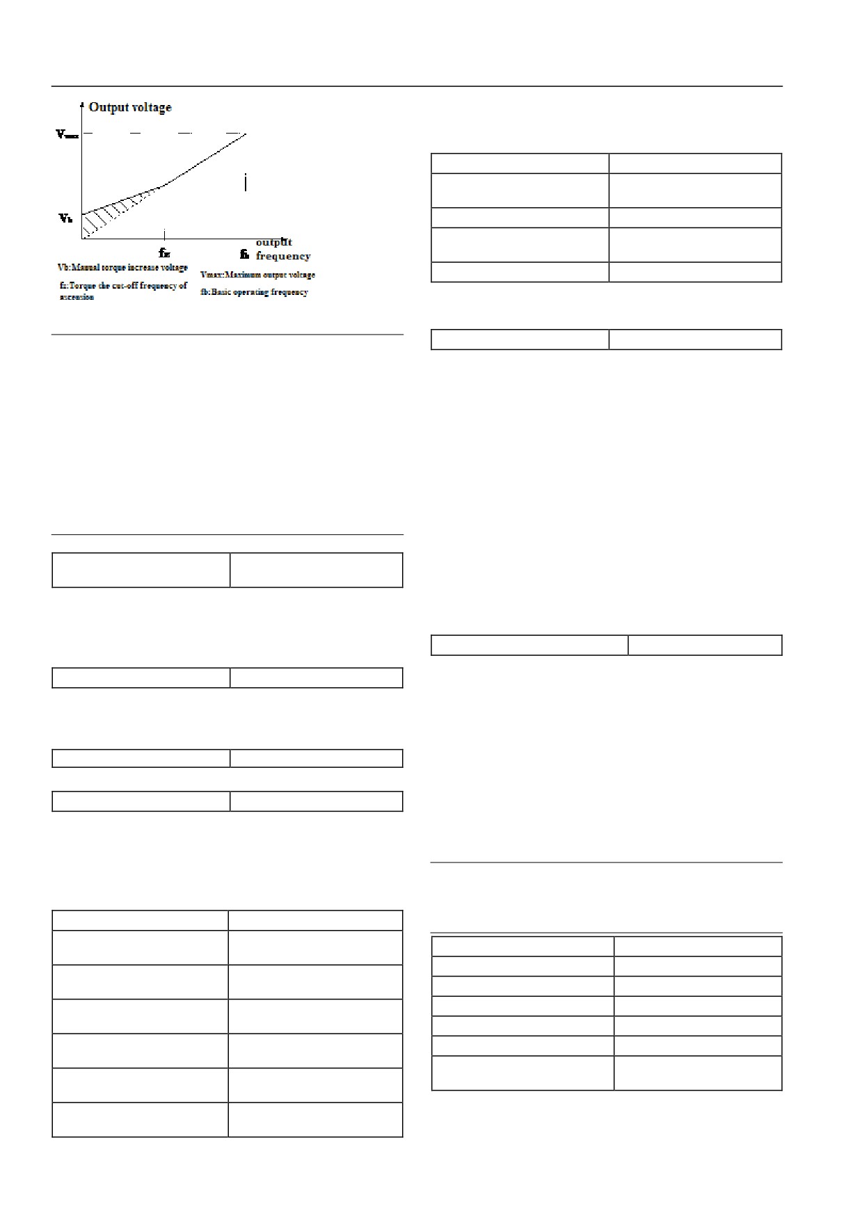
Chapter VI Function Code Details
The group function code defines the HSD2000 motor 2 for V / F
set way to meet the needs of different load characteristics. See
detailed description of function code, in P06.00 ~ P06.06:
P06.19 motor 2 torque lifting
0.0~30.0%【0.0%】
P06.20 motor 2torque lifting
0.0%~50.0%【10.0%】
cut-off point
P06.21 motor 2 base frequency
1.00~1000.0Hz【50.00Hz】
P06.22 motor 2 maximum
0~480V
output voltage
P06.23 motor 2 stability factor
0~255【10】
Refer to P06.07~P06.11 description.
Figure 6-20: torque rise (rise: shadow)
P06.24 AVR function
0~2【1】
Note
0: no action
1.This parameter setting can lead to improper motor heat or
1: action
over current protection.
2.See the definition of fz function code P06.08.
2: only no action in deceleration
3.When driving synchronous motors, torque recommended to
AVR is automatic voltage adjusting.
be used to enhance and adjust V / F curve according to motor
When the input voltage deviates from rated value, the function can
parameter and use the occasion.
be maintained by constant output voltage, so under normal
4.The maximum output voltage Vmax corresponds to the
circumstances should AVR action, especially in the input voltage
motor rated frequency, and thus need to set P03 or P04 group
is higher than the rated value when.
set motor rated frequency correctly according to the selected
When the deceleration stop, select AVR does not operate,
motor.
deceleration time is short, but running current is slightly larger;
P06.08 motor 1 torque lifting
choose AVR always action, smooth motor deceleration, running
0.0%~50.0%【10.0%】
cut-off point
current is small, but the deceleration time longer.
This function defines the percentage of manual torque cutoff
6.1.8Speed Control Parameter (P07 group)
frequency relative to enhance the basic operation frequencyP06.09,
see Figure6-20 in fz. The cutoff frequency determined by any
P07.00 Speed Feedback Option
0, 1【0】
applicable P06.00 V / F curve.
HSD2000 has two speed feedback channel options.
P06.09 motor 1 base frequency
1.00~1000.0Hz【50.00Hz】
0: local PG feedback channel
The basic operation is the minimum frequency when the servo
It is applicable for PG feedback of asynchronous motor.
drive output highest frequency voltage corresponding to the motor
1: Expansion PG feedback channel
is generally rated frequency. As in Figure6-18 fb:
It is suitable for both synchronous and asynchronous motor PG
P06.10 Reserved
Reserved
feedback in setting P07.00 = 1, the need to use PG expansion
Reserved function.
card.
P06.11 motor 1 stability factor
0~255【10】
In with PG vector control, with PG V / F control mode, you need
This function is used to suppress the natural oscillation with servo
to set the correct speed feedback channels, otherwise motor
drive and motor generated. If the output current constant load
cannot operate normally.
changes repeatedly, on the basis of the factory parameter adjusting
Note
the function code size can eliminate oscillation motor running
smoothly.
P07.00 function code parameter only for the default choice of
motor 1, if you select the motor 2 (P02.01 to 1), it should be
P06.12 motor 2V/F curve setting
0~3【0】
selected by function code P04.33 encoder.
P06.13 motor 2V/Ffrequency
P06.15~P02.05【0.00Hz】
P07.01 ASR1-P
0.1~200.0【20.0】
value P3
P07.02 ASR1-I
0.000~10.000s【0.200s】
P06.14 motor 2V/F voltage value
P06.16~100.0%【0.0%】
P07.03 ASR1output wave filter
0~8【0】
V3
P0615 motor 2V/Ffrequency
P07.04 ASR2-P
0.1~200.0【20】
P06.17~P06.13【0.00Hz】
value P2
P07.05 ASR2-I
0.000~10.000s【0.200s】
P0616 motor 2V/F voltage value
P07.06 ASR2output wave filter
0~8【0】
P06.18~P06.14【0.0%】
V2
P07.07 ASR1/2 switching
0~100.0%【10.0%】
P06.17 motor 2V/Ffrequency
frequency
0.00~P06.15【0.00Hz】
value P1
Function code P07.00 ~P07.07 may be effective in control
P06.18 motor 2V/F voltage value
0.0~P06.16【0.0%】
modes of vector control and PG V/F control modes.
V1
58
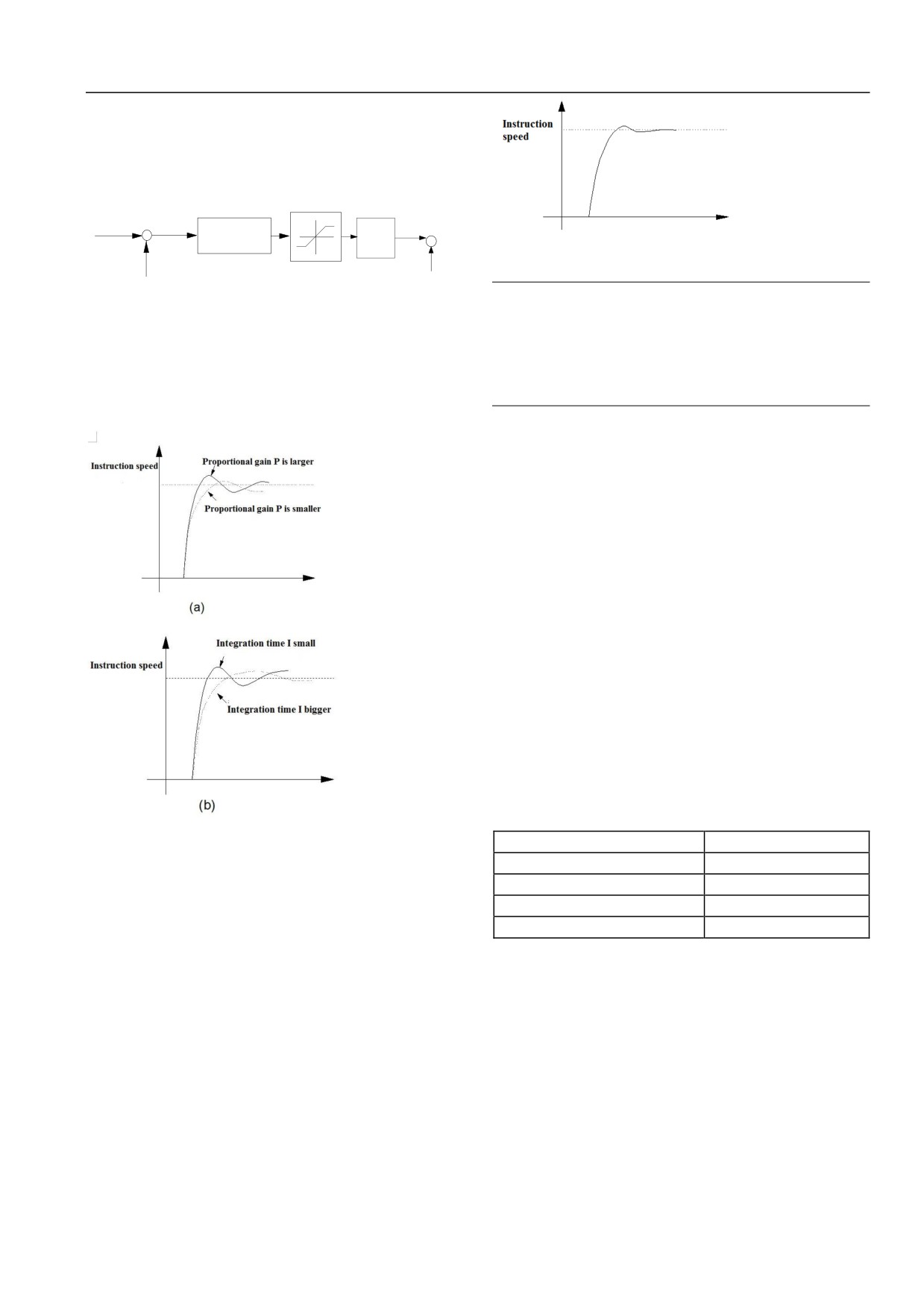
Chapter VI Function Code Details
In vector control mode by setting the speed regulator, proportional
gain P and integral time I may change the vector control speed
response characteristics.
1.Speed regulator (ASR) constituted as Figure6-21 shows. Figure
in KP is the proportional gain P; TI is the integral time I.
转矩电流
频率指令
+ 速度误差
1
给定+
K
)
输出
p(1+T
滤波
-
i S
-
转矩偏
Figure 6-23: Step response with fine dynamic performance
实际速度
转矩限定
置给定
P08.10 P08.11
Note
PI parameter was not selected, the system quickly start to the
Figure 6-21: Speed adjustor Figure
high-speed, over-voltage fault may occur
(if no external
The integration time is set 0 (P07.02 = 0, P07.05 = 0) when no
braking resistor or brake unit), which is due to overshoot in
integral action, speed loop is a simple proportional regulator.
the rate of decline over the medium-range regenerative brake
system of the state energy feedback cause. It can be avoided
3. Speed regulator (ASR) P proportional gain and integral time
by adjusting PI parameter.
I is tuning.
3.Speed regulator (ASR) adjustment PI parameter in high / low
speed situations.
If the system is on high and low load operation has a rapid
response requirements, you can set ASR switching frequency
(P07.07). Usually the system is running at low frequencies, to
improve the dynamic response characteristics, can increase
proportional gain P and reduce integration time I. Generally in the
following order to adjust the speed regulator parameter:
1) Select the appropriate switch frequency P07.07.
2) Scaling at high speed and integration time gain P07.01
P07.02, ensure that the system does not occur and the
oscillation characteristics of a good dynamic response.
3) P07.04 proportional gain and integration time adjustment at
low speeds P07.05, to ensure that no low-frequency
oscillation and good dynamic response characteristics.
4.Speed regulator (ASR) of output after a delay wave filter to
obtain a given torque current. P07.03, P07.06, respectively, is the
time constant of ASR1 and ASR2outputwave filter.
Figure 6-22 speed
(ASR) step response and PI parameter
P07.08 speed limit mode
0~2【0】
Increase the proportional gain P, can speed up the dynamic
P07.09 speed limit channel 1
0~1【0】
response of the system; But P is too large, the system tends to
P07.10 speed limit channel 2
0~1【0】
oscillate.
P07.11 speed limit value 1
0.0%~100.0%【100.0%】
Reducing the integral time I, can accelerate the dynamic response
P07.12 speed limit value 2
0.0%~100.0%【100.0%】
of the system; But I too small, the overshoot is large and easy to
Function code P07.08 ~ P07.12 only valid in torque control
produce oscillations.
mode, the rest of the control is invalid.
Usually first adjust the proportional gain P, to ensure the system
By setting function code P07.08 ~ P07.12 under torque control
does not oscillate maximize the premise P; then adjust the
motor's speed limit value. In torque control mode if the motor
integration time I make the system both fast response without
rotational speed limit value. Internal torque instruction to switch
overshoot. Figure6-23 is P, I select a good speed step response
to the speed regulator (ASR) output, control motor speed is not
time curve
(velocity response curve can be analog output
out of control.
terminalAO1, AO2 observation, see P11 parameter group).
Speed limit mode:
0: Forward limit value by the speed limit channel 1 (P07.09)
setting, reverse limit value by the speed limit channel 2 (P07.10)
setting.
1: Reversible limit value is limited by the speed channel 1 (P07.09)
setting.
59