HSD2000 Series Servo Drive. Operation Manual V1.2 - page 2
Chapter IV Servo Drive Wire Distribution and EMC Installation Instructions
Chapter IV Servo Drive Connection and EMC Installation Instructions
The chapter shows connection and wiring of servo drive, the question of meeting EMC requirements.
Danger
·Servo drive cover plate shall be not opened until cutting servo drive power supply and waiting for at least 10 minutes.
·Servo drive internal wiring work shall be implemented by trained and authorized qualified professionals.
·When connect emergency stop or safety circuit, wiring shall be inspected carefully before and after operation.
·Before energize, the servo drive voltage degree shall be inspected carefully. Otherwise the casualties and equipments damage will be occurred.
! Attention
·Before using, the servo drive rated input voltage shall be checked to consist with AC power supply voltage.
·Before factory, servo drive has passed the puncture test. Puncture test shall be not implemented on servo drive.
·External braking resistor or braking unit shall refer to chapter II.
·Don’t connect the power supply lines with U, V, W.
·The ground wires are usually copper wire above 3.5mm diameters. The ground resistance shall be less than 10Ω.
·Current leakage is happened in servo drive. The specified value shall be determined by using condition. Servo drive and motor shall be grounded
for safety. RCD is required to install with B type. The current leakage current setting value shall be 300mA.
·For input over current protection and power out maintenance, the servo drive shall connect to power by air switch or fuse switch.
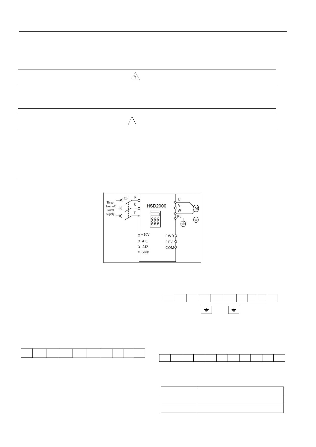
During pilot running, connection as Figure4-1 may be used:
Figure 4-1 Main Circuit Simple Connection Figure
4.1Main Circuit Terminal Connection and Configuration
R
S
T
P1
(+)
PB
(-)
U
V
W
4.1.1 Main Circuit Input and Output Terminal Type
Main circuit terminal includes four types with different servo
drive models. Refer to below:
Terminal Type 1
Terminal Type 3
Applicable
machine:
HSD2000-4T-1R5~HSD2000-4T-004.
Applicable
machine:
HSD2000-4T-018~HSD2000-4T-055.
Terminal logo may be seen below:
Terminal logo may be seen below:
PE
R
S
T
(+)
(-)
PB
U
V
W
R
S
T
P1
(+)
PB
(-)
U
V
W
PE
Terminal type 1~terminal type 3 logos shall refer to table 4-2.
Terminal Type 2
Applicable
machine:
HSD2000-4T-5R5~HSD2000-4T-015.
Table 4-2 Main Circuit Terminal Description
Terminal logo may be seen below:
Terminal name
Function description
R, S, T
Three-phase AC input terminal
P1, (+)
DC reactor connection terminal, copper
20
Chapter IV Servo Drive Wire Distribution and EMC Installation Instructions
Terminal name
Function description
1.Obvious breaking device (such as disconnect switch) shall be
installed between grid and servo drive to ensure personal safety in
short circuit when factory
equipment maintenance.
(+), PB
Braking resistor connection terminal
2.When contactor is used for power supply control, it shall be not
used for control power up and down of servo drive.
(+) (-)
DC power supply input terminal
3.DC Reactor
U, V, W
Three-phase AC output terminal
For prevent servo drive influence from power supply, protect
servo drive and higher harmonic wave; the DC reactor may be
, PE
Grounded terminal
configured in the following conditions.
z
When the same power node supplied to servo drive is
Terminal type 4
equipped with switching electric capacity reactive power
Applicable machine: Terminal logo above HSD2000-4T-075 may
compensation device screen or controlled silicon phased load,
be seen below:
the electric capacity device screen wsitch shifting may cause
Input terminal
reactive transients causing mutations net pressure. The
(Machine top)
phased load will cause harmonic wave and grid waveform
PE
R
S
T
gap. Above will damage input rectifier circuit of servo drive.
output terminal
z
When imbalance in the servo drive power of three-phase
(Machine bottom )
power supply is not greater than 3%;
PE
U
V
W
P1
(+)
z
When power factor of servo drive input end is required to be
(-)
improved to greater than 0.93;
Input terminal (top of the machine)
Output terminal (bottom of machine)
z
When servo drive accesses large-capacity transformer, input
power circuit current may damage rectifier circuit. In general,
when servo drive power supply capacity is greater than
550kVA; or the power supply capacity is 10 times greater
Table 4-3 Main Circuit Terminal Description
than servo drive capacity; DC reactor will be configured in
Terminal name
Function description
servo drive.
R, S, T
three-phase ACinput terminal
4.AC Input Reactor
The AC input reactor may be equipped in the following conditions:
DC reactor connects to terminal,
P1, (+)
when grid waveform distorts seriously; when higher harmonic
copper short circuit when factory
wave influences between servo drive and power supply can’t meet
DC power supplu input terminal;
requirements (DC reactor is equipped on servo drive). AC input
(+), (-)
reactor may improve power factor of servo drive input.
external brake unit DC output terminal
5.AC Output Tractor
U, V, W
Three-phase AC output terminal
When wiring between servo and motor exceeds 80 meters, it is
PE
Grounded terminal
suggested to use bunch wire and install AC output reactor
restricted high frequency oscillation. Motor insulation, too large
leakage current and servo drive frequently protection are avoided.
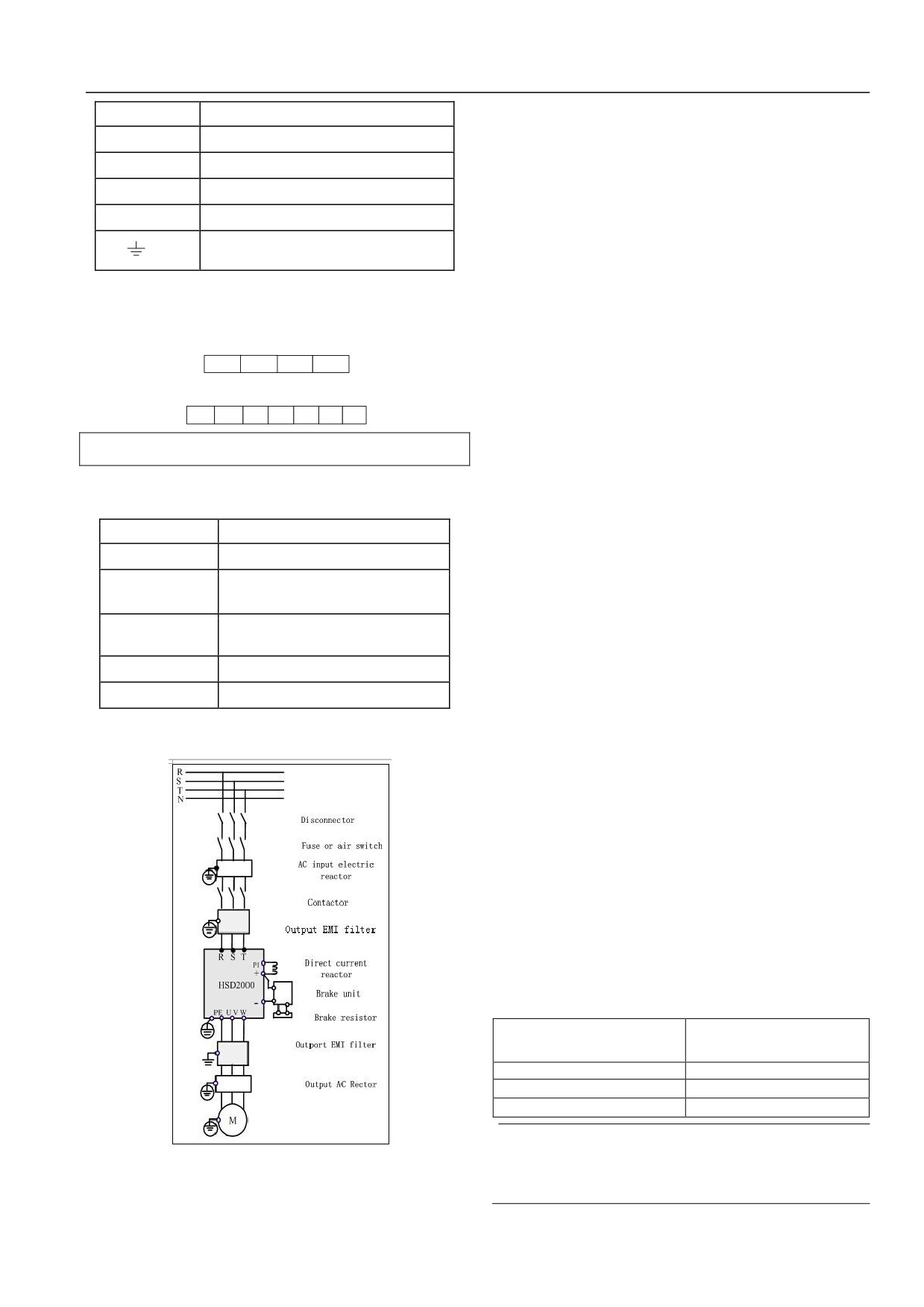
4.1.2Connect servo drive and optional accessories
6.Input EMI
EMI wave filter may be used to restrict high-frequency noise from
servo drive power line.
7.Output EMI wave filter
EMI wave filter may be used to restrict interference noise and
leakage current conductors from servo drive output.
8.Safety ground wire
Leakage current exists in servo drive. Servo drive and motor shall
be grounded for safety. The ground resistance shall be less than
10Ω. The ground wire shall be as short as possible. The wire
diameter shall meet standard of table 4-4.
Note: Value in the table will be correct when the same metal uses
in both conductors. If not, section area of conductor protection
shall be ensured by equivalent conductivity coefficient in table
4-4.
Table 4-4 Section area of conductor protection
The minimum section area of
Phase conductor section area in
related protection conductor Sp
installation S (mm2)
(mm2)
S16
S
16<S35
16
35<S
S/2
Note
Figure 4-2 Servo Drive and Optional Accessories
1.Input (output) EMI wave filter shall be installed to close to
Connection
servo drive as much as possible. The installation method
shall refer to Optional Accessories Installation of 4.3.
21
Chapter IV Servo Drive Wire Distribution and EMC Installation Instructions
2.Technical parameters of optional accessories may refer to
3.Servo drive output: it is suggested to use #6 cable, wiring
Optional Accessories of 2.4.
terminal
(RNBS14-6), heat shrink tubing
(φ18.0, black,
125 ℃, 600V). The specific process may refer to table 4-4.
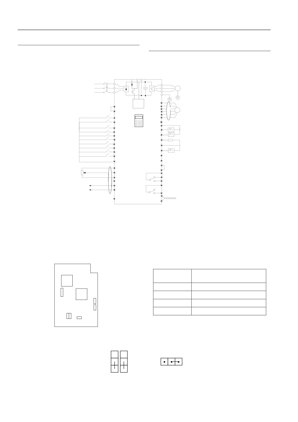
4.1.3Basic Operation Connection Connection
Basic operation connection connection is shown as figure below:
(+)
PB
(-)
Breaker
Three
R
R
U
phase
380V S
S
V
M
50/60Hz
T
W
T
PE
auxiliary power
PGP
supply
P24
COM
A+
PLC
A-
PG
HSD2000
B+
Forward/stop command
B-
FWD
Reverse/stop command
REV
PE
Multi-function input 1
GND
Dc voltage/current meter
X1
Multi-function input 2
AO1
X2
Multi-function input 3
AO2
Voltage/current signal
X3
Multi-function input 4
X4
P24
Multi-function input 5
X5
Frequency table (open collector
Multi-function input 6
DO
output)
X6
Multi-function input 7
COM
output 0-24v
pulse signal
X7
Multi-function input 8
X8
Y1
output 1
Open collector output
COM
Y2
output 2
CME
+10V
common port
COM
analog input
AI1/AI2
TA
-10V
TB
Programmable relay output
Simulation of differential input
GND
TC
AI+
BRA
-10V~10V
Programmable relay output
AI-
BRC
RS485+
PE
standard RS485
COM port
RS485-
Figure 4-3 basic connection Figure
4.2Control Circuit Connection and Configuration
4.2.1Relative position and function introduction of jumper
Before servo drive puts into use, terminal connection shall be implemented correctly. Function description of jumper switch and slot may
refer to table 4-6.
Table 4-6: Jumper Switch and Slot Function of User
Number
Function
DSP
CN2
Encoder of 5V and 12V jump
FPGA
J3, J4
Encoder of 5V and 12V jump
CN4
CN9.
CN8, CN9
Expansion Card 24V Power Supply
CN4
Expansion PG Card Slot
CN8
J4
J3
CN2
Figure 4-4: Jumper Switch Position Figure of Control Plate
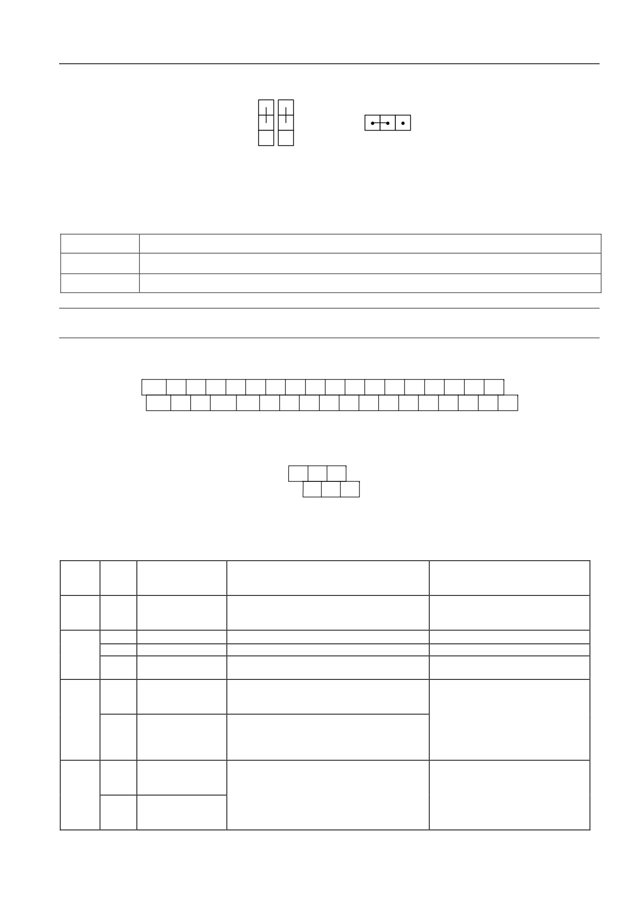
J3, J4 and CN2 jump shall be used coordinately. Jump using method of 5V encoder is shown in the figure below:
3
3
CN2
J4
J3
12V
5V
1
1
3
1
22
Chapter IV Servo Drive Wire Distribution and EMC Installation Instructions
Jump using method of 12V encoder is shown in the figure below:
3
3
CN2
J4
J3
12V
5V
1
1
3
1
4.2.2Control circuit terminal wiring
Before servo drive puts into use, terminal connection shall be implemented correctly. Function description of jumper switch and slot may
refer to table 4-6.
Table 4-6: Control Circuit Terminal Function
Number
Function
CN5~7,CN13~15
Analog input and output port, RS485 communication port, switch input and output port, encoder input signal terminal
CN16
Two relay output ports
Note
It is suggested to use wiring of greater than 1mm2 as connect wire of control circuit terminal.
Terminal arrangements of control circuit terminal CN5~7, CN13~15 are shown as figure below:
+10V
GND
AI+
AI-
AI1
AI2
GND
A+
A-
PGP
COM
PLC
P24
COM
CME
Y1
Y2
DO
-10V
AO1
AO2
485+
485-
PE
B+
B-
FWD
REV
X1
X2
X3
X4
X5
X6
X7
X8
Figure 4-5: CN5~7, CN13~15 Terminal Arrangement Figure
Terminal arrangements of control circuit terminal CN16 is shown as figure below:
TA
TB
TC
BRA
BRC
Figure 4-6: CN16 Terminal Arrangement Figure
Terminal function description may be shown in table 4-7 and table 4-8.
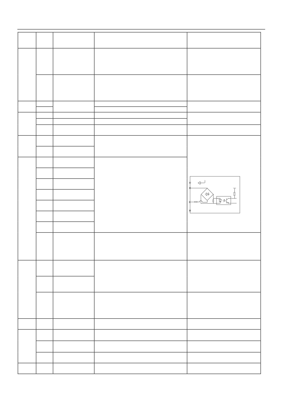
Table 4-7: Interface Board Terminal CN5~7, CN13~15 Function Table
Termina
Type
l screen
Name
Terminal function description
Specification
printing
Ground of terminal wiring shielding layer; analog signal
Internal connect with main circuit wiring
Shield
PE
Shield ground
wire, 485 communication wire; shielding layer of motor
terminal PE
cable may be connected to the terminal.
+10
+10V power supply
External supply +10V reference power supply
Maximum allowable output current 5mA
Power
-10
-10V power supply
External supply-10V reference power supply
Maximum allowable output current 5mA
supply
+10V-10V power
GND
Analog signal+10V, -10V power supply reference
Internal separated with COM and CME
ground
Acceptable analog voltage or current single-ended input,
Analog single-ended
AI1
voltage/current input shall be selected by function code
input AI1
Input voltage range: -10V~10V (input
P11.00
( reference ground: GND)
Analog
impedance: 45kΩ) ,resolution: 1/4000
Acceptable analog voltage or current value
input
input current range: 0mA~20 mA,
Analog single-ended
single-endedinput, voltage/ current input shall be
AI2
resolution: 1/2000
input AI2
selected by function code P11.00
( reference ground:
GND)
Analog voltage
When accept analog voltage values differential input,
AI+
differential inputAI+ or
AI+ will be the forward phase input end. AI- will be
Analog
single-ended input
Input voltage range: -10V~10V (input
reverse input end; when accept analog voltage values
input
Analog voltage
impedance: 15kΩ), resolution: 1/4000
single-ended input, AI+ will be signal input end,AI-will
AI-
differential inputAI- or
be connected to GND ( reference ground: GND).
single-ended input
23
Chapter IV Servo Drive Wire Distribution and EMC Installation Instructions
Termina
Type
l screen
Name
Terminal function description
Specification
printing
When provide analog voltage/ current values output, 25
types of values may be represented; output voltage,
Voltage output range: 0/2~10V
AO1
Analog output1
current may be selected by function code P11.16. The
current output range: 0/4~20mA
factory default shall be output voltage. See the function
Analog
code P11.17 description ( reference ground: GND)
output
When provide analog voltage/ current values output, 25
types of values may be represented; output voltage,
Voltage output range: 0/2~10V
AO2
Analog output2
current may be selected by function code P11.1. 6. The
current output range: 0/4~20mA
factory default shall be output voltage. See the function
code P11.21 description. ( reference ground: GND)
Commun
RS485+
RS485 communication
485 difference signal positive end
Standard RS485 communication port may
ication
RS485-
port
485 difference signal negative end
use twisted-pair wire or shield wire
A+,A-
Encoder A phase signal
encoder A Phase difference inputsignal
Input maximum frequency100kHz
B+,B-
Encoder B phase signal
Encoder B phase difference inputsignal
Encoder
Provide power supply to external encoder ( reference
Output voltage : 12V
PGP
Encoder power supply
ground : COM)
Maximum output current: 250mA
Operatio
Forward operation
FWD
n
command terminal
The forward and reverse switch command may refer to
control
Reverse operation
P10.08 two-wire three-wire control function description
REV
terminal
command terminal
Optocoupler isolation input
Multi-function input
X1
input impedance: R=3.3kΩ; maximum
terminal 1
input frequency: 200Hz
Multi-function input
X2
input voltage range: 20V~30V
terminal 2
+24V
Multi-function input
P24
X3
terminal 3
The programmable may be defined as multifunction
PLC
+3.3V
Multi-function input
switch values input terminal. See the 6.1.11 switch value
X4
terminal 4
input and output terminal parameters (P10 group) of
Multi-fun
R
Multi-function input
P10.00~P10.07 input terminal function introduction
ction
X5
Xi、FWD、REV
terminal 5
input
COM
Multi-function input
terminal
X6
terminal 6
Multi-function input
X7
terminal7
In addition to be X8 ordinary multi-function terminal (as
Optocoupler isolation input equivalent
X1~X7), the program may be implemented as high
figure is shown above
Multi-function input
X8
speed pulse input end. See the 6.1.11 switch value input
input impedance: R=2kΩ
terminal 8
and output terminal parameters (P10 group) of
Maximum input frequency: 100kHz
P10.00~P10.07 input terminal function introduction.
input voltage range: 20~30V
Bidirectional
The programmable may be defined as multifunction
Optocoupler isolation output
Y1
open-collector output
switch values output terminal. See the 6.1.11 switch
maximum working voltage: 30V
terminal 1
value input and output terminal parameters (P10 group)
maximum output current: 50mA
Bidirectional
Multi-fun
of P10.18 and P10.19 output terminal function
the method may refer to P10.18~P10.19
Y2
open-collector output
ction
introduction (common terminal: CME)
description
terminal 2
output
The programmable may be defined as multifunction
terminal
pulse signal output terminal. See the 6.1.11 switch value
Open-collector pulse
Output frequency range: determined by
DO
input and output terminal parameters (P10 group) of
output terminal
P10.33. the maximum of 100kHz
P10.32 output terminal function introduction (common
terminal: CME)
Power
P24
+24V power supply
External supply+24V power supply
Maximum output current: 200mA
supply
Multi-function input
Multi-function input terminal common terminal
X1~X8, FWD, REV common terminal,
PLC
common terminal
(short circuit with P24 when factory)
PLC will be isolated with P24 internal
+24V power supply
Three public terminals. Using together with other
Common
COM
COM and CME、GND internal isolation
common terminal
terminals.
terminal
Y1, Y2output common
Multi-functionoutput terminal Y1, Y2 common terminal
CME
COM is isolated with CME and GND
terminal
(short circuit with COM by manufacturer)
Internal connects with main circuit terminal
Shield
PE
Shield ground
Shielding layer ground terminal
PE
24
Chapter IV Servo Drive Wire Distribution and EMC Installation Instructions
Table 4-8: Interface Board Terminal CN16 Function Table
Terminal
Type
screen
Name
Terminal function description
Specification
printing
TA-TB: normally close,TA-TC: normally
TA
open
Contact capacity :
The programmable may be defined as multifunction
Relay
250Vac/2A (COSФ=1)
pulse signal output terminal. See the 6.1.11 switch value
output
TB
Relay output
250Vac/1A (COSФ=0.4)
input and output terminal parameters (P10 group) of
terminal1
30Vdc/1A
P10.21 output terminal function introduction.
The method may refer to P10 description.
TC
Relay output terminal input over voltage is
class II.
BRA-BRC: normally open
BRA
Contact capacity:
The programmable may be defined as multifunction
250Vac/2A (COSФ=1)
Relay
pulse signal output terminal. See the 6.1.11 switch value
250Vac/1A (COSФ=0.4)
output
Relay output
input and output terminal parameters (P10 group) of
30Vdc/1A
terminal2
P10.20 output terminal function introduction.
The operation method may refer to P10
instruction. Relay output terminal input over
BRC
voltage is class II.
Note
“AI+, AI-”is function code AI3 in P11.
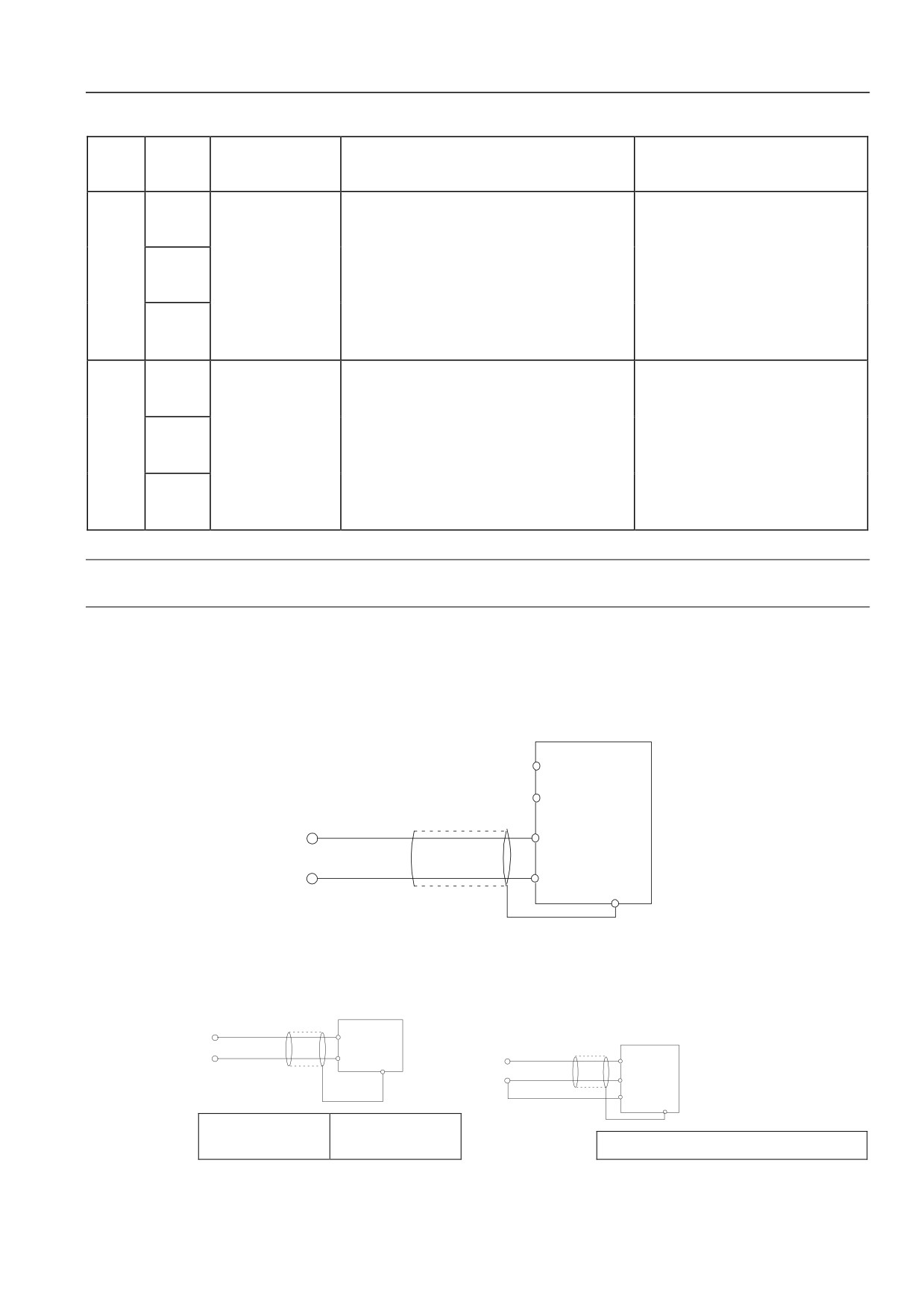
Analog input terminalconnection
1) AI1,AI2 terminal acceptable analog voltage or current value single-ended input,voltage/current input will be selected by function code
P11.00. The connection method is shown below:
P11.00 unit digital:
HSD200
AI1 0 :
Voltage input
0
1:
Current input
tens
P11.00
:
+10
digital
AI2 0 :
Voltage input
-10
1:
Current input
AI1,AI2
GND
PE
-10~ +10V
Shielded wire
Or 0~20mA
Figure 4-7: AI1,AI2 Terminal connection Figure
2) AI+, AI-terminal accepts analog voltage differential input or analog voltage single-ended input. The connection method is shown below:
HSD2000
AI+
HSD2000
AI-
AI+/AI -
-10V :
+10V
PE
-10V :
+10V
Analog voltage
Shielding wire
AI - /AI+
difference input
Shielding wire
GND
PE
Analog
voltage
Shielding wire
differential input
Shielding wire
Figure 4-8: AI+, AI-terminal Differential Voltage Input connection Figure
Figure 4-9: AI+,AI-terminal Single-ended Voltage Input connection Figure
25
Chapter IV Servo Drive Wire Distribution and EMC Installation Instructions
Analog Output Terminal Connection Method
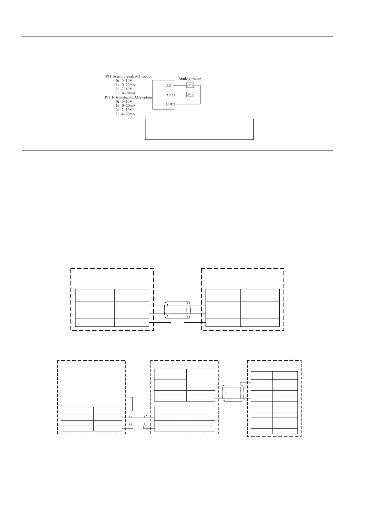
Analog output terminal AO1 and AO2 external analog gauge may show variety of physical values. The function code P11.16 will select
output current (0/4~20mA) and voltage (0/2~10V). Terminal connection method is shown below:
P11.16 unit digital: AO1 option
P11.16 tens digital: AO2 option
Figure 4-10: Analog Output Terminal Connection
Note:
1.When using analog input, wave filter electric capacity or common mode choke may be installed between input signal and GND.
2.Voltage of analog input signal is not suggested to exceed 15V.
3. Analog input and output signal is easy to be disturbed by external. Shield cable with good ground shall be used in connection.
Length of connection shall be as short as possible.
4. The maximum voltage of analog output terminal is 15V.
Communication Port Connection
HSD2000 servo drive provides RS485 serial communication port to users. The following connection method may composite single
master/multi-slave system or single slave/multi master system. The host(PC computer or PLC controller) software may be used to achieve
real time monitor of network. Remote control, automatic control may be finished and achieve complicated motion control (such as
unlimited multi segment PLC operation).
1. Servo drive connects with host with RS485 interface:
HSD2000
Host
Terminal
Terminal
Terminal
Terminal name
Shield cable
instructions
name
instructions
Signal -Terminal
RS485-
RS485-
Signal - Terminal
Signal +Terminal
RS485+
RS485+
Signal+Terminal
Signal ground
GND
GND
Signal ground
Figure 4-11: RS485-RS485 Communication connection
2. Servo drive connects with upper computer with RS232 interface:
Host
RS485/232 Transverter
RS232(DB9)
Terminal
instructions
Terminal name
Shield
Signal
Pin No.
cable
HSD2000
5V
upply
+5V
PE
Case
Transmit data
TXD
RXD
2
line
Receive data
line
RXD
TXD
3
5V Power
GND
GND
5
DTR
4
Terminal
Shield
Terminal
Terminal
DSR
6
instructions
Terminal name
cable
name
instructions
RI
9
Signal - Terminal
RS485-
RS485-
Signal - Terminal
CD
1
Signal + Terminal
RS485+
RS485+
Signal + Terminal
RTS
7
Signal ground
GND
GND
Signal ground
CTS
8
Figure 4-12: RS485- (RS485/232) -RS232 Communication connection
26
Chapter IV Servo Drive Wire Distribution and EMC Installation Instructions
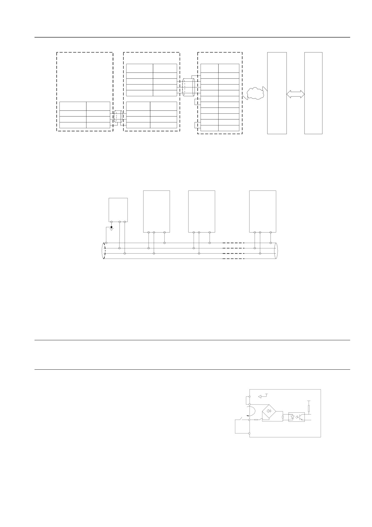
3.Servo drive connects remotely with host by MODEM:
RS485/232 Transverter
Modem
Terminal
Signal
Terminal name
Shield
Pin NO.
HSD200
instructions
cable
0
5V Power supply
terminal
+5V
PE
Case
Transmit data
line
TXD
RXD
2
Receive data
RXD
TXD
3
line
Mode
RS23
5V Power
GND
GND
5
PSTN
Host
m
2
DTR
4
Terminal
Terminal
DSR
6
Terminal name
Terminal name
instructions
instructions
RI
9
Signal - Terminal
RS485-
RS485-
Signal -Terminal
CD
1
Signal + Terminal
RS485+
RS485+
Signal +Terminal
RTS
7
Signal ground
GND
GND
Signal ground
CTS
8
Shield cable
Figure 4-13: RS485- (RS485/232) - (Modem-Public Network-Modem) -RS232 Communication connection
In the figure above, if the interface connected with modern is RS485, the RS232/RS485 converter shall be used to connect.
4.Connect wire hang in the same RS485 system of certain servo drives:
When certain servo drives hang in the same system RS485, the communication disturb will be added. The connection becomes very
important. We suggest users to wire as the following methods:
HD200
HSD200
PLC
HSD2000
0
0
SG
+RS485-
+RS485-
+RS485-
+RS485- GND
GND
GND
RS485 cable
RS485 Cable
Figure 4-14: PLC and Servo Drive Recommended Connection (servo drive and motor well grounded)
If the above connection could not communicate in normal, the following measures may be implemented:
1) Single supply to PLC (or upper computer) or separate power supply. In heavy external disturb field, the communication wire shall
be isolated.
2) The RS485/RS232 convert module shall be separate power supply.
3) Use magnetic ring on communication wire;
4) If applicable, the servo drive carrier frequency may be lowered.
Note
1. RS485 converter with isolation shall be used in larger disturb field.
2. RS485 cannot afford voltage above30V.
Multi-function Input Terminal and Operation Control
Terminal Connection
+24V
HSD2000 multi-function input terminal is equipped with full
P24
+3.3
bridge rectifier circuit as shown in figure 4-15. PLC is public
PLC
V
terminal of X1~X8, FWD, REV. Current through PLC terminal
+
Current
will be either source current or sink current. Interface of external
R
-
K
with X1~X8, FWD, REV shall be flexible. The typical wiring
X1: X2...X8
FWD: REV
HSD200
COM
0
method shall be as follows:
1.Dry Contact Method
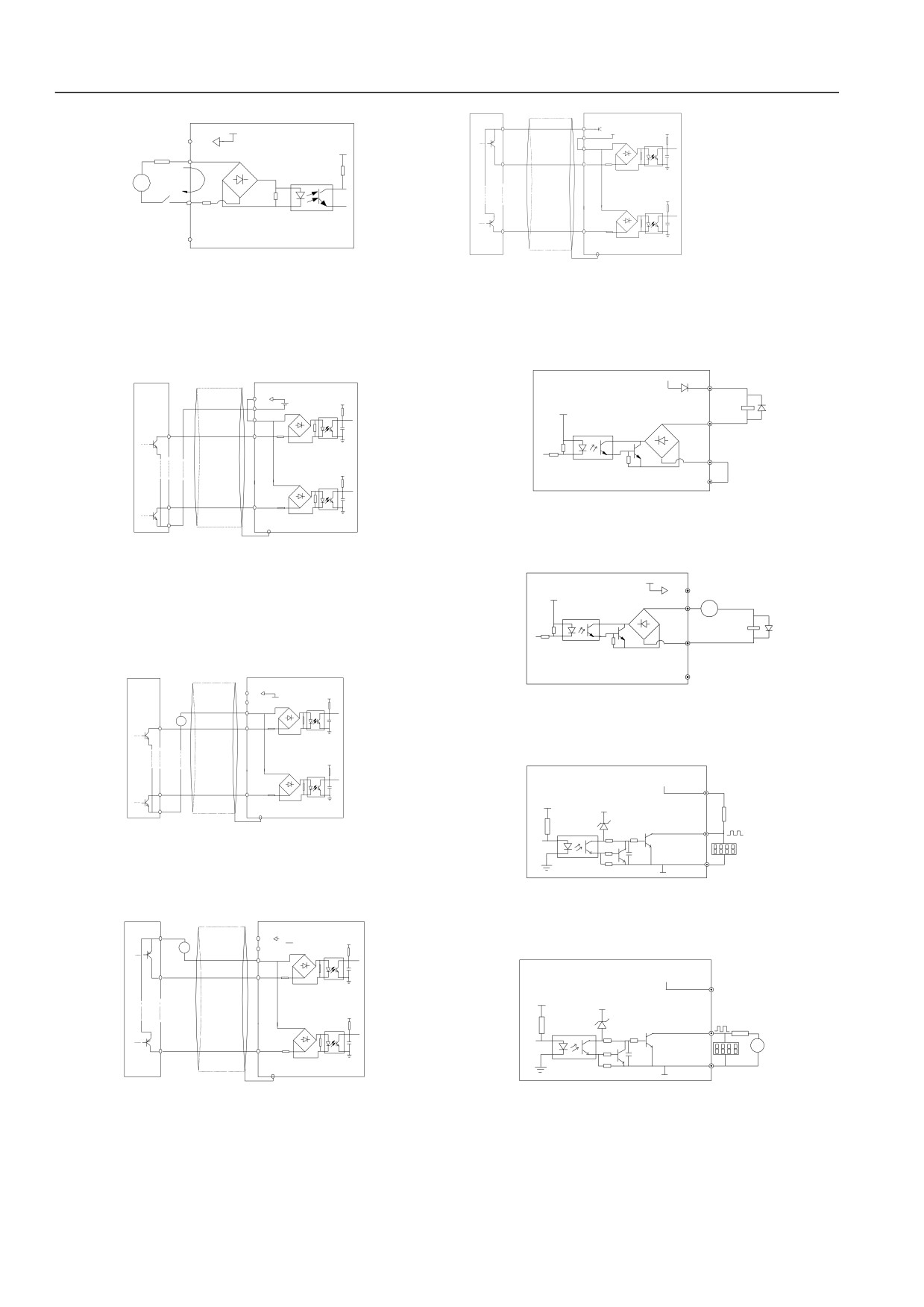
Figure 4-15: Internal 24V Power Supply Wire Connection
1) Internal 24V power supply in servo drive shall be used. The
2) External power supply wiring (power supply shall meet UL
wiring is shown in figure 4-15.
CLASS 2 standard, 4A fuse is required to install between power
supply and interface) is shown as figure 4-16 (wiring between
27
Chapter IV Servo Drive Wire Distribution and EMC Installation Instructions
External controller
HSD200
PLC and P24 terminal shall be removed).
0
COM
P24
+3.3
+24V
●
D2 +
P24
COM
24Vdc
V
-
+3.3
PLC
Fuse
PLC
V
1
FWD
+
+
DC
-
Current
R
+3.3
-
V
K
X1: X2...X8
FWD: REV
10
X8
COM
HSD2000
Shielding Wire
PE
Proximal Ground
Figure 4-16: External 24V Power Supply Wire Connection
Figure 4-20: External Power Supply Drain Connection
2. Source (Drain) Mode
Multi-function output terminalconnection
1) The servo drive internal + 24V power supply shall be used. The
1.Multi-function output terminalY1, Y2 may use servo drive
external controller connection mode is NPN common emitter
output. It is shown in figure 4-17:
internal 24V power supply. The wiring may refer to 0.
External controller
HSD2000
+24V
P24
P24
D2
+
+3.3V
COM
24Vdc
-
+5V
Relay
PLC
Y1 : Y2
1
FWD
CME
+3.3V
HSD2000
COM
10
X8
Figure 4-21: Multi-function Output Terminal Connection 1
PE
COM
Shielding Wire
Proximal Ground
2.Multi-function output terminalY1, Y2 may use external power
supply. The wiring may refer to 0.
Figure 4-17: Internal +24V Power Supply Servo Drive Source Connection
+24V
P24
2) The servo drive internal + 24V power supply shall be used.
+5V
DC
Y1 : Y2
+ -
The external controller connection mode is NPN common
Relay
emitter output. It is shown in figure 4-18: (wiring between
CME
PLC and P24 terminal shall be removed).
External Controller
HSD200
0
HSD2000
COM
P24
D2
+
+3.3V
COM
-
24Vdc
Figure 4-22: Multi-function Output Terminal Connection 2
24V
PLC
+
1
-
FWD
3.Digital pulse frequency output DO may use servo drive internal
24V power supply. The wiring may refer to Figure 4-23.
+3.3V
HSD2000
+24V
10
X8
P24
+5V
+24V
Shielding Wire
PE
4.7k
Proximal Ground
DO
Figure 4-18: Internal +24V Power Supply Servo Drive Drain Connection
COM
Digital frequency
3) External power supply source connection shall be used: (wiring
meter
between PLC and P24 terminal shall be removed)
Figure 4-23: Output Terminal DO Connection 1
External Controller
HSD2000
4.Digital pulse frequency output DO may use external power
P24
D2
+
24V
+
COM
+3.3V
supply. Wiring may refer to Figure 4-24.
-
-
DC
24V
PLC
1
FWD
HSD200
+24V
0
P24
+5V
+24V
+3.3
V
4.7k
DO
10
+
X8
-
DC
COM
Shielding Wire
PE
Digital frequency
Proximal Ground
meter
Figure 4-24: Output Terminal DO Connection 2
Figure 4-19: External Power Supply Source Connection
Relay Output Terminal TA, TB, TC Connection
4) External power supply drain connection shall be used: (wiring between
The surge voltage absorbing circuit may be installed on driving
PLC and P24 terminal shall be removed).
inductive load (electromagnetic relay, contactor). When the RC
absorbs circuit (the current leakage shall be less than keep current
28
Chapter IV Servo Drive Wire Distribution and EMC Installation Instructions
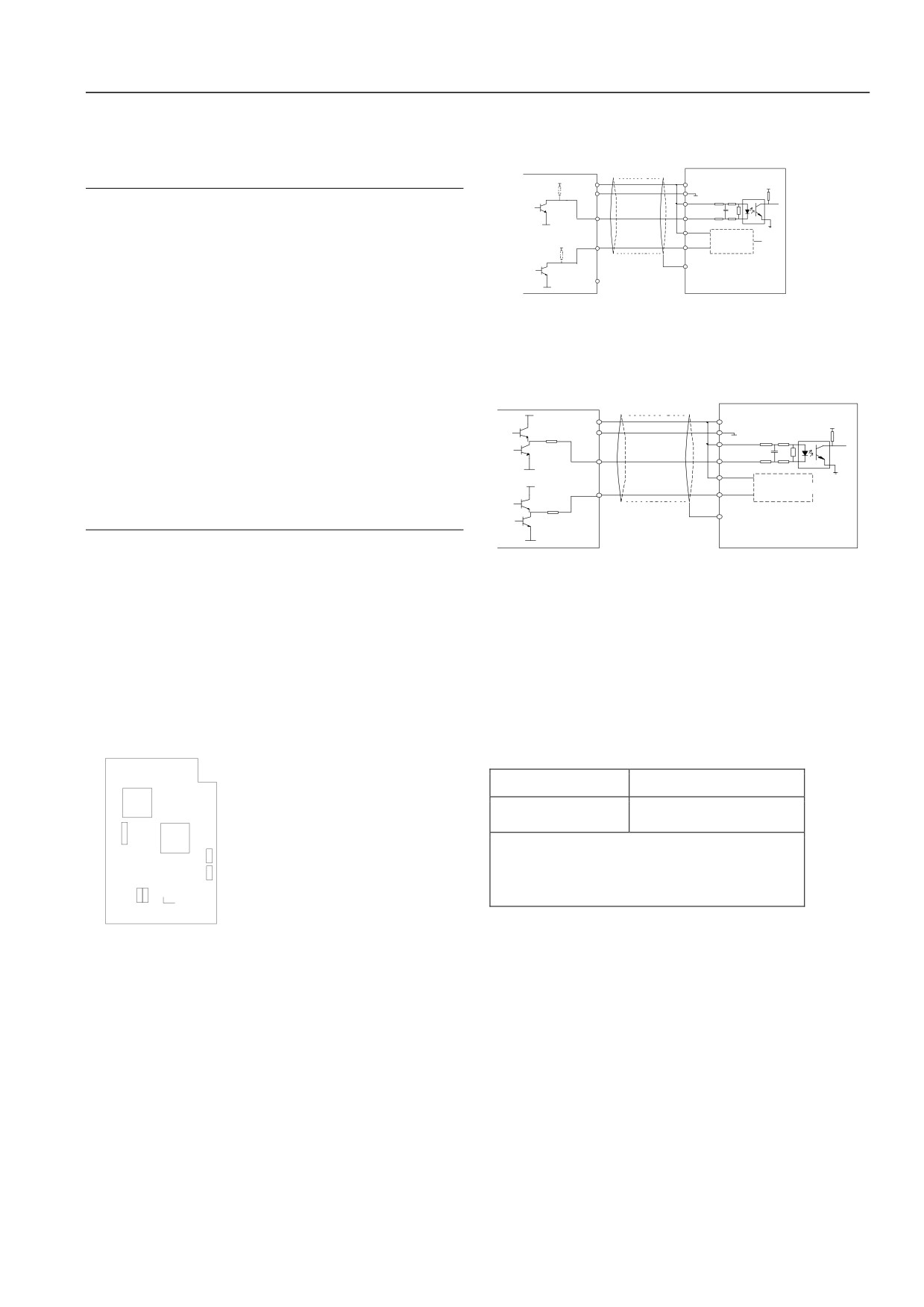
of controller or relay), voltage dependent resistor, freewheeling
1.PG output signal shall be collector open circuit signal.
diodes (used in DC electromagnetic Loop; polarity shall be noted
Connection with interface board terminal is shown as figure 4-25:
in installation); the circuit absorb parts shall be installed both ends
(dotted line in figure is voltage output encoder)
of contactor of both ends in relay or contactor.
Using
shielding
wire
HSD2000
VCC
VCC
PGP
:
3.3V
0 V
Note
COM
A
A+
A
1.The short circuit shall be not between P24 terminal and
GND
A-
Interface
B+
circuit is the
B
COM terminal. Otherwise the control plate will be damaged.
B
VCC
same as A
Shielding layer close
B-
2.The control terminal shall be connected by multi-core shield
connection
PE
PE
ground
cable or twisted wire (1mm2 more).
GND
3.When using the shield cable, close end of cable shielding
Figure
4-25: Collector Open Circuit Signal PG Wiring
(close to servo drive) layer shall be connected to ground
Schematic Diagram
terminal PE of servo drive.
4.When wiring arrangement, the control cable shall be more
2.PG output signal is push pull signal. Connection with interface
than 20cm far away from main circuits and high voltage lines
board terminal is shown as figure 4-26 below:
(power supply line, motor line, relay line, contactor connection
Using
shielding
line). The placement shall be avoided. The vertical
wire
HSD200
VCC
0
arrangement is suggested to prevent servo drive error action
VCC
PGP
: 3.3V
0 V
caused by disturb.
COM
A
A+
A
5.For not 24V relay of Figure 4-21 and Figure 4-22, applicable
GND
A-
Interface
resistor shall be selected as relay parameters. Serial shall be
B+
B
VCC
circuit is the
B
implemented in relay loop.
same as A
Shielding layer close
B-
connection
PE
6.Digital output terminal cannot bear voltage of 30V.
PE
ground
GND
Encoder Wiring Precautions
Figure 4-26: Push Pull Signal PG Wiring Schematic Diagram
Encoder (PG) signal line shall be separated with main circuit and
other power lines. Close parallel wiring shall be avoided. Encoder
wiring shall be shield wire. Shielding layer closed to servo drive
shall connect PE terminal.
4.3Optional Accessories Installation
Optional accessories of HSD2000 servo drive is connected through servo drive control plate. Optional accessories terminal
base
arrangement on control plate is shown in figure below:
Table 4-9: Interface Board Terminal CN4 Menu
Number
Function
CN4
Expansion PG Card Interface*
CN
CN4
9.
Note:
For detailed description of expansion PG card, refer to 2.4.2
CN
CN
8
expansion PG card introduction.
J4
J3
2
Figure
4-27: Optional Accessories Terminal Base Position Schematic
Diagram
4.2Installation Instructions Met EMC Requirement
Work principle of servo drive determines the production of noise. The EMC problem will be brought. For reducing or avoiding external
disturb of servo drive, the chapter shows EMC installation method from noise restriction, site connection, ground, leakage current and
power supply wave filter. The introduction may be used as site installation.
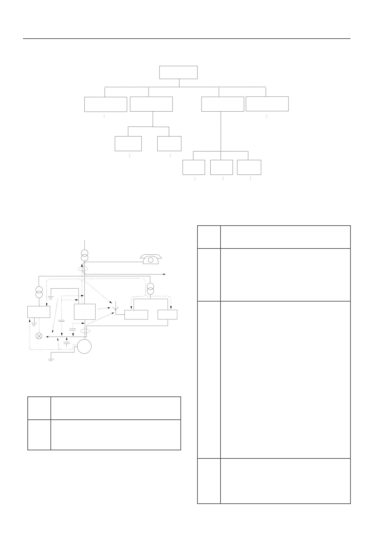
4.4.1Noise Suppression
Noise from servo drive working may influence near equipments. The influence degree is related with servo control system, equipment
noise immunity, wiring environment, place distance and ground methods.
29
Chapter IV Servo Drive Wire Distribution and EMC Installation Instructions
Noise type
Noise
category
Electrostatic
Circuit
Space
Electromagnetic
induction noise
transmission noise
transmission noise
induction noise
Path:
Path:
:
Current
Power line
grounding
transmission
wire noise
noise
Path:
Path :
Motor line
Power cord
Servo drive
radiation
radiated
radiated
noise
noise
noise
Path:
Path:
Path:
Figure 4-28: Noise Classification
Noise
Noise Spread Path
spread
Strategies of reducing influence
path
When power supply of peripheral equipments and servo
drives us the same system, the noise inverse power supply
:
Phon
wire spread of servo drive will produce error action to
e
③
equipments of the same system. The following measures may
be used to prevent: install noise wave filter on input end pf
:
servo drive; isolation transformer or power supply wave filter
:
:
is used to isolate noise.
instrument
:
:
Process measuring instrument, radio device, sensor and
Sensor power
Servo drive
Wireless
signal wires. If the devices are in the same cabinet with servo
supply
Instrument
:
installation
drive and closing wiring, it may be influenced by space
:
noise. The following strategies will be used:
:
(1) For equipments and signal wires easy to be influenced,
Sensor
:
its installation shall be far away from servo drive. The
Motor
signal wire shall be shielding. The shielding layer shall be
:
grounded. The signal wire cable shall be in metal tube and
far away from servo drive, input and output wire. When the
Figure 4-29: Noise Spread Path Schematic Diagram
signal cable passes through power cable, the two device
Noise Suppression Basic Strategies
④⑤⑥
shall be orthogonal.
(2) Radio noise wave filter and a linear noise wave filter
Table 4-10: Noise Suppression Strategies
(Ferrite Common Mode Chokes) shall be installed on input
Noise
and output of servo drive to restrain radiated noise of power
spread
Strategies of reducing influence
wire.
path
(3) The motor cable wire shall be placed in barrier of
When peripheral equipments form closed loop by servo drive
larger thickness. It may be placed in larger thickness (2mm
wiring, the error action will be produced when current
more) tubes or buried in cement tanks. The power wire shall
②
leakage of servo drive. Error action will be reduced when
be set into metal tube with shield ground (4 core cable is
the equipment is not grounded.
used in motor cable; the one is grounded on servo drive side;
another is connected to motor shell).
When the signal wire wiring parallel or binding with power
wire: since the electromagnetic induction noise and
electrostatic induction noise, the noise may be spread in
① ⑧
signal wire. The error action may be occurred sometimes.
The wiring above shall be avoided. The related equipments
shall be far away from input and output wire of servo drive.
30
Chapter IV Servo Drive Wire Distribution and EMC Installation Instructions
Noise
spread
Strategies of reducing influence
path
When signal wire and power wire use shield wire, they shall
be set into metal tube respectively for better effects.
Distances between metal tube shall be at least 20cm.
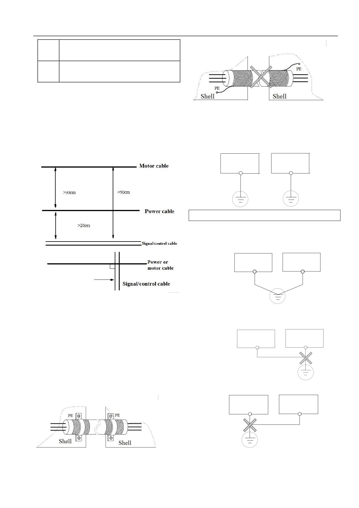
4.4.2Site Connection Requirement
Shell
For avoid coupling of disturb, the control cable, power supply
cable and motor cable shall be installed respectively. In general,
Figure 4-32: Wrong Shield Ground Method
enough distance shall be ensured. When the cable installs
4.4.3Ground
parallel with long extension distance. Vertical pass through shall
be implemented when signal cable passes through power supply
Specified Earth Electrode (best)
cable.
Servo
Other
Drive
Equipments
PE
Servo drive
Other equipments
Figure 4-33: Ground Schematic Diagram 1
Common Earth Electrode (possible)
Other
Servo Drive
Equipments
PE
Figure 4-30: System connection
When the motor cable is larger or the cable section area is larger,
Figure 4-34: Ground Schematic Diagram 2
derating shall be implemented. Since the larger of cable section
Common Ground wire (not allow)
area, the greater electric capacity to ground, the greater leakage
current to ground. When using the cable of larger section area, the
Other
Servo Drive
output current shall be lowered. When area increases once, the
Equipments
current will be lowered by about 5%.
PE
Shield/armored cable: the high frequency low impedance shield
cable shall be used. Such as braided copper wire, aluminum wire
mesh or barbed wire. In general, the control cable shall be shield
cable. The shield metal wire mesh shall be connected to metal
Figure 4-35: Ground Schematic Diagram 3
cabinet of servo drive through cable clips of both sides.
Other
Servo Drive
Equipments
PE
Figure 4-36: Ground Schematic Diagram 4
Shell
In addition, the following shall be noted:
Figure 4-31: Correct Shield Ground Method
31
Chapter IV Servo Drive Wire Distribution and EMC Installation Instructions
Distributed
z
For possible low of different ground system impedances, the
Power
supply
QF
capacitance between
maximum ground cable standard size shall be used. The flat
lines
R
cable is used well. For cable of the same section area, high
Servo Drive
Motor
S
frequency impedance of flat conductor is smaller than round
distributed
T
conductor.
capacitance
of motor
z
One wire of 4 core motor cables shall be grounded on servo
Cable to
ground
drive side. The other side shall be connected to motor ground.
capacitance
If motor and servo drive have specific earth electrode with
good effects.
Figure 4-38: Leakage way
z
When all the ground ends of system connects together, the
Earth Leakage Current
leakage current will be noise source to influence equipments.
The ground ends of servo drive, other audio devices, sensor
The leakage will flow into either servo drive system or other
and computer shall be isolated.
equipments (by earth wire). The leakage current may cause error
z
For lower high frequency impedance, fixed screw of
action of leakage breaker, relay or other equipments. The higher
equipments may be as high frequency terminal connected to
of servo drive carrier wave frequency, the greater leakage current.
rear cabinet. The insulation paint of fixed point shall be
The larger the motor cable, the greater of leakage current.
removed.
Restrain Measures:
z
The ground cable shall be as short as possible. The ground
z
Reduce carrier wave frequency. The motor noise will be
point shall close to servo drive.
increased.
z
The ground cable shall be far away from connection of I/O in
z
The motor cable shall be as short as possible.
noise-sensitive devices. The ground wire shall be as short as
z
The leakage breaker designed for leakage of high harmonic
possible.
wave/surge shall be used for servo drive system and other
systems.
4.4.4 Installation Requirements of Relay, Contactor and
Wiring Leakage Current
Electromagnetic Brake
Leakage current of electric capacity flowed to servo drive output
Relay, contactor and electromagnetic brake shall be equipped
cable. The higher harmonic wave may cause error action of
with surge suppressors including installation outside servo drive
thermal relay, especially for small capacity (7.5kW less) servo
cabinet.
drive. When the connection is larger (50m more), the leakage
current will be relative increased. The error action of external
Diode
thermal relay may be caused.
Restrain measures:
24VDC
z
Reduce carrier wave frequency. The motor noise will be
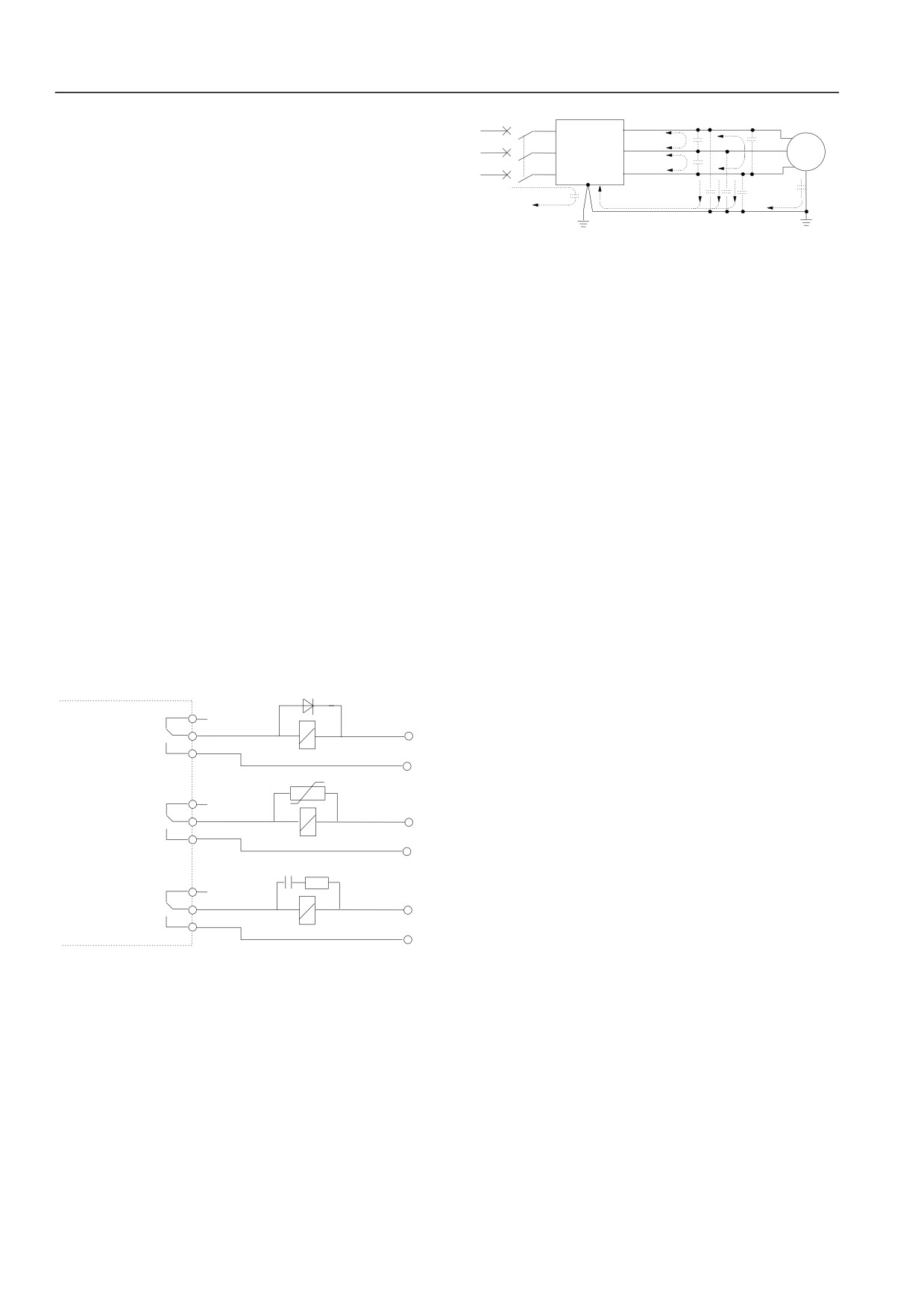
increased.
Piezoresistor
z
Install reactor in output side.
Servo
Drive
For motor protection, the temperature sensor is recommended to
220VAC
use for monitoring motor temperature. The overload protection
function
(electric thermal relay) of servo drive may replace
RC- Filter
external thermal relay.
4.4.6Correct EMC Installation of Servo Drive
220VA C
Figure 4-37: relay, contactor and electromagnetic brake
Partition Principle
In the driving system made up by servo and motor, the servo drive,
4.4.5Leakage Current and Strategies
control device and sensor shall be in the same cabinet. The noise
emitted outside shall be restricted on main connection point. The
Leakage current passes through servo drive input and output
radio noise wave filter and line reactor shall be installed in cabinet.
electric capacity and motor electric capacity. Its capacity is
The cabinet internal shall meet electromagnetic compatibility
determined by wiring electric capacity and carrier wave frequency.
requirements.
The leakage current includes earth leakage current and wiring
leakage current.
During mechanical/system design phase, the isolate noise source
in space and noise receiver shall be considered. The measure is the
most effective and the most expensive measure. In the driving
system made up by servo and motor, the servo drive, control
device and sensor shall be the noise source. The noise receiver
shall be automatic device, encoder and sensor.
32
Chapter IV Servo Drive Wire Distribution and EMC Installation Instructions
According to electrical characteristics, the mechanical/system
Motor cable and control cable shall use shield or armored. The
shall be divided into different EMC areas. It is suggested to place
internal shield metal wire mesh shall connect both sides of ground
device in the area as shown in figure 4-39.
wire. Metal wire mesh ends shall be avoided to be twisted to
Main power supply
pigtails. The shield effects in high frequency will be influenced.
cord
Electrica
Zone V
l cabinet
Incoming line
The cable clip shall be used.
filter
The good conductivity of installation plate, screw and servo drive
Zone
I
metal cabinet shall be ensured. Tooth broken washer and
Control
Zone Ⅲ
Input reactor
device
conductive mounting plates shall be used.
(Computers, etc.)
Servo
Drive
Manufacturin
When individual sensitive equipment is in site, power supply
Ⅱ
g Machine
Sensor
Mechanic
wave filter shall be installed in sensitive equipment side to reduce
(such as temperature,
Motor
liquid, etc.)
Linear noise
Zone
al system
Zone
filter
Ⅳ
Ⅵ
cost.
Ground
plate
Motor
cable
Detection signal
4.4.7Power Supply Wave Filter User Guide
line
The power supply wave filter may be used for equipments which
Figure 4-39: servo drive EMC schematic diagram
generate strong interference and sensitive to external disturb.
Description:
Wave filter of the power supply wire shall be bi-directional
Ⅰarea: Control power supply transformers, control systems and
low-pass wave filter. It allows DC or 50Hz power frequency
sensors.
current. The high frequency EMI current is not allowed to pass.
Ⅱarea: Signal and control cable interface parts,certain immunity
Wave Filter Action of Power Supply Wire
shall be required.
The equipments may meet conducted emissions and conducted
Ⅲarea: Line reactor, servo drive, brake unit, contactor;
susceptibility requirements of electromagnetic compatibility
Ⅳarea: Output noise wave filter and connection parts;
standards. It may restrain radiation emission of equipments.
Ⅴ area: Power supply
(including radio noise wave filter
The electromagnetic interference generated from equipments may
connection);
be prevented into power supply wire. The interference on power
supply wire is prevented into equipments.
Ⅵarea: Motor and cable
z
Space of areas shall be isolated to achieve electromagnetic
Power Supply Wire Wave Filter Installation Common Error
decoupling.
1. Power supply input wire is longer.
z
The minimum distance of areas shall be 20cm.
Wave filter in cabinet shall be installed near outlet of power
z
Decoupling of areas shall be implemented by plate. Cables in
supply wire. Power supply input of wave filter in cabinet shall be
different areas shall be put into different cable tubes.
as short as possible.
z
Wave filter shall be installed in areas interface.
2. Input and output wires of power supply wire are too close.
z
All the communication cables
(such as RS485) shall be
When the wires are too close, the high frequency interference
introduced from cabinet. All the signal cables shall be shield.
signal will be coupled by input and output wires of wave filter.
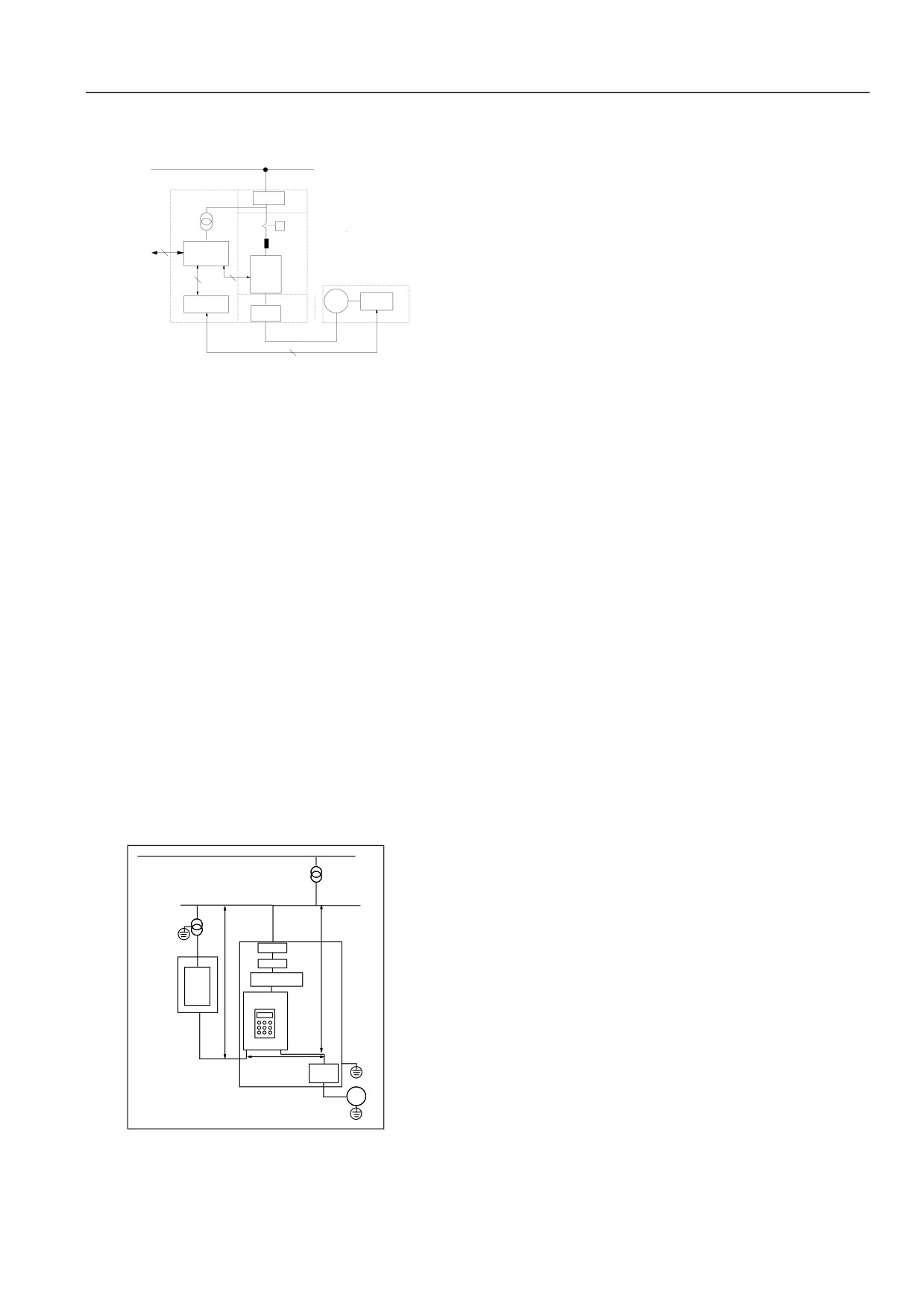
Servo Drive Electrical Installation Schematic Diagram
Wave filter of power supply will be out of action when remove the
side path.
10kV
Power
3.Wave filter ground bad
transformer
Shell of wave filter shall be connected with metal cabinet.
Isolation
transformer
Drive power
Specific grounded terminal is usually used in filter of wave filter.
>20cm
cable
If the wave filter connects to shell by one conductor wire, it is
Instrument
Air switch
power cable
useless to high frequency interference signal. Impedance
Filter
>30cm
AC input
(non-resistance) of long wire in high frequency is longer,effective
Metal
PLC or
reactor
Metal
cabinet
instrument
cabinet
Servo drive
side affection shall be not acted. The correct installation method
shall be: close the wave filter shell to metal chassis conducting
Controlling
cable
plane directly. The insulation paint shall be removed.
Motor
cable
>50cm
Output AC
reactor
4.4.8Servo Drive Radiation Emission
Motor
The run principle of servo drive determines inevitable of servo
drive radiation emission. The servo drive is placed in metal
Figure 4-40: servo drive schematic diagram
cabinet. Instruments outside metal cabinet shall take less influence
The ground wire of motor cable shall be grounded on servo drive
of radiation emission in servo drive. The external connection
side. The motor and servo drive had better ground respectively.
cable is the main emission source. Cable wiring shall be based on
33
Chapter IV Servo Drive Wire Distribution and EMC Installation Instructions
requirements of the chapter. It may restrain radiation emission of
cabinet designing. Isolation, cable wiring, shield and lap shall be
cable.
considered.
When the servo drive is in the same metal cabinet with other
control device, the partition principle above shall be considered in
34
Chapter V Servo Drive Rapid Operation Guide
Chapter V Servo Drive Rapid Operation Guide
The chapter shows the production information, operation procedure and method of servo drive operation.
5.1Servo Drive Operation Panel
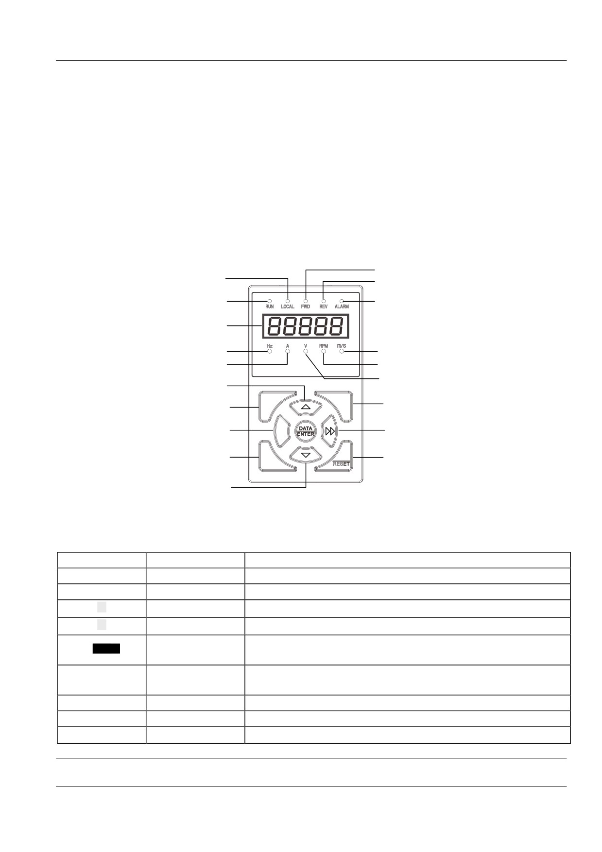
5.1.1Operation Panel Appearance and Key Function Description
Operation panel is the main command accepting parameter display unit of servo drive which includes LED and LCD. Dimension and
operation of LED and LCD are almost the same. The LCD operation panel equips with text information of English and Chinese,
explanation of data type. LED operation panel shall be standard configuration. The LCD operation panel may be selected as actual
demands. To facilitate the description, the LED operation panel is described as an example below. See the figure 5-1:
Forward direction
Command channel
Reverse direction
lamp
lamp
Run status lamp
Alarm lamp
Digital display
Frequency lamp
Line speed lamp
Speed lamp(round per
Current lamp
minite)
Voltage lamp
UP
MENU
LOCAL
Command channel
ESC
MENU/ESCAPE
change
JOG
JOG
Shift
Stop/fault
RUN
STOP
RUN
reset
DOWN
Table 5-1: LED operation panel schematic diagram
There are 9 keys on servo drive operation panel. Function of each key is defined as the table 5-1:
Table 5-1: Operation Panel Menu
Key
Name
Function
MENU/ESC
Programming / Exit key
Enter or exit programming status
DATA/ENTER
Function/Data key
Enter next menu or data identification
▲
Increment key
Increment of data or function code
▼
Decrement key
Decrement of data or function code
Under editing, the modified position of setting data may be selected. Under other status, the status
Displacement key
parameter may be displayed shifted.
Operation command
LOCAL
Select operation command channel in order, press the DATA/ENTER key to ensure
channel shifting key
JOG
Jog key
Under operation panel, press the key for jog operation
RUN
Operation key
Under operation panel, press the key for operation
STOP/RESET
Stop/Reset key
Stop or fault reset
Note
Functions of RUN, STOP/RESET, and LOCAL are limited by function code P00.06.
35
Chapter VI Function Code Details
5.1.2LED Digital and Indicator Description
Stop
parameter
Digital tube
display
lights in turn
Five positions and
8 segments LED digital tube,
5 unit
state
indicators and 5 status indicators are equipped on servo drive
LED operation panel. As shown in figure 5-1. The digital
display tube may display status parameters, function code
Figure 5-2: LED operation panel
parameters and fault alarm code of servo drive. 52.1.1.1.1.1.1.rs
correspond to
5 units indicates respectively. LCD operation
Note
panel is equipped with LED display screen and
5 status
1.When functions of all the keys are normal, the servo drive
indicators.
will exit self inspection status automatically after self
5 status indicators: status indicator is located on the display of
inspection finishes. Otherwise the self inspection status will
digital tube. From left to right as operation indicator, operation
keep to full power-down of servo drive.
command channel indicator, forward indicator, reverse indicator
2.During self inspection, the key pressing order shall follow
and warning indicator. The meaning of indication, see table 5-2.
the procedure 2. Otherwise the servo drive has no response.
3.When the key locking function is set, the operation panel
Table 5-2: Status Indicator Description
shall be locked automatically after self inspection.
Status
Indicate servo drive current
Indicator
Operation panel self inspection operation shall be implemented
display
status
under parameter display. Self inspection shall be not realized
Operation status
Extinguish
Stop status
indicator
Light
Operation status
under function code editing status.
Light
Operation panel control st2.1
.1.2.
Example 2: Setting Function Code Parameter
Operation command
Extinguish
Terminal control status
channel indicator
Example: change the function code P02.04 from 50.00Hz to
Flash
Serial port control status
49.99Hz.
5.1.3Operation Mode of Operation Panel
1.Under data display status, press the MENU/ESC key to enter
a level P00.00.
The servo drive may be operated through operation panel. The
2.PressXX key to select the second highest position.
followings are common operation modes. The specified function
code structure description shall refer to chapter VIIII—the
3.Press ▲ key to change P00.00 into P02.00.
function code table.
4.PressXX key to select unit digit.
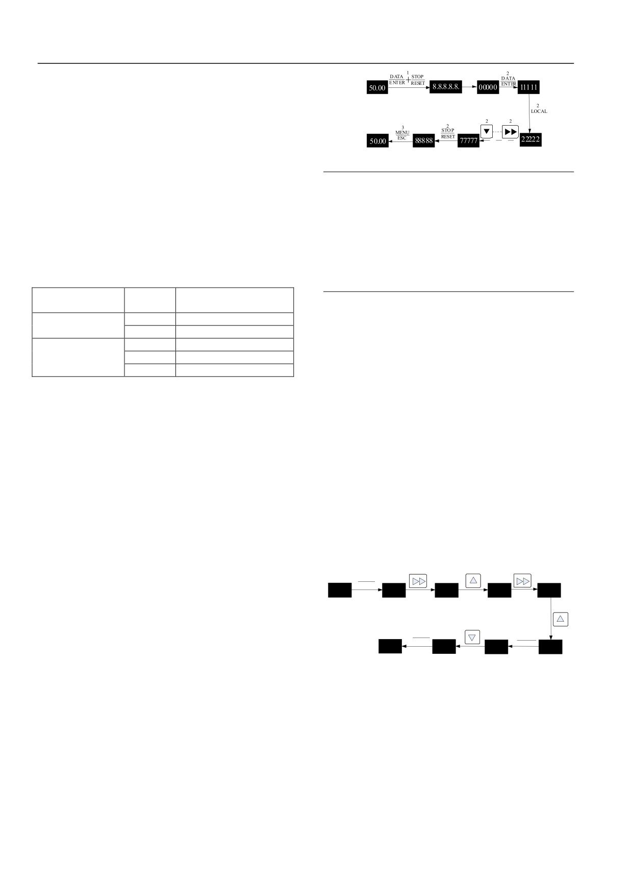
Example 1: Operation Panel Self Inspection
5.Press ▲ key to change P02.00 into P02.04.
Before using the operation panel, self inspection of HSD2000
6.Press DATA/ENTER to enter B level menu.
operation panel shall be used to inspect digital tube, indicator
7.Press▼ key to change 50.00 into 49.99.
display and key function for normal. The following procedures
8.Press DATA/ENTER key to identify modification. Return to
shall be referred:
A level menu to finish. The above operation procedures may
1.Under stop status, press the DATA/ENTER key for long time,
refer to figure below:
then press STOP/RESET key to enter self inspection status.
1
2
3
4
MENU
During self inspection, all the 5 LED digital tubes of operation
ESC
50.00
P00.00
P00.00
P02.00
P02.00
panel indicators shall be lighted. Then all the indicators are
Shutdown
First level menu
Time high scintillation
lighted, the LED will display “00000”.
parameter
Flickering bits
5
Display status
2.Press DATA/ENTER key, LOCAL key, XX key, ▲key, JOG
8
7
6
ENTER
ENTER
key, RUN key, ▼ key and STOP/RESET key in order.
DATA
DATA
P
02.04
49.99
50.00
P02.04
Bold numbers in figure indicate the flashing
In normal, press the DATA/ENTER, the LED will shift from
:
digit
Second level menu
“00000” to “11111”. With pressing key, the changing will be
Figure 5-3: function code parameter
happened. The
“88888” will be displayed when press
Under function parameter display status, the function code shall
STOP/RESET key.
be not modified until parameter flashes. The possible reasons
3.Press MENU/ESC key, the LED will back to stop parameter
include:
display status. The self inspection will be finished.
1.The function parameter shall be not modified. Such as actual
Operation procedures above may refer to the figure below:
inspection parameter, operation record parameters, etc.
2.The function code shall be not modified in operation. It shall
be not modified until stop.
3.Protection of parameter: when the function P00.03 is 1 or 2,
the function shall be not modified for avoiding error
36
Chapter VI Function Code Details
operation. When editing the function code parameter, the
Press LOCAL key, the LOCAL indicator will light when select
P00.03 shall be set as 0 first.
operation command channel. The LOCAL indicator will be off
Note: function code number and function code parameters are
when select terminal operation command channel. The LOCAL
displayed in the same line. Press DATA/ENTER to enter from
indicator will flash when select serial port operation command
function code number to function code parameter. When the
channel. The LOCAL indicator will flash in switching. The
function parameter shall be not edited, no cursor is displayed.
channel switching will be not finished until DATA/ENTER keys
Since no response in pressing▼and▲key, press MENU/ESC
ensure in 3 seconds. Otherwise the LOCAL indicator will return
key to back to function code display status.
to original status in 3 seconds.
Example 6: User Password Authentication Unlock
Example 3: Switch Display Status Parameter
Servo drive provides password protection function for
Servo drive parameters of operational panel displayed under
parameter protection. After setting the user password, user shall
stop status may be set by function code P17.02, such as setting
input user password correctly to enter function code editing
frequency, bus voltage
(refer to P17 group function code
status after entering MENU/ESC key. Factory password shall be
detailed description). After setting parameters displayed under
entered correctly in factory setting parameter area.
servo drive stop status, the status parameters may be referred by
XX key of operational panel. Figure5-4 shows status
Note
parameter display example of P17.02 FFF in drive stop.
Don’t try to modify factory setting parameter. When
parameter setting is not applicable, the servo drive is easy to
be abnormal or destroy.
Set frequency Working speed Set speed Busbar voltage Run linear
velocity
The function code P00.02 may be used to set user password.
Analog closed-
Set linear
loop feedback
velocity
Specified may refer to 6.11 system management (P00 group).
It is assumed that the user in force is “1368”. The servo drive
Figure 5-4: stop status parameter operation
has been locked without any operation. The following operation
Operation switching status method is implemented as above.
may be used to enter user password and finish user unlock.
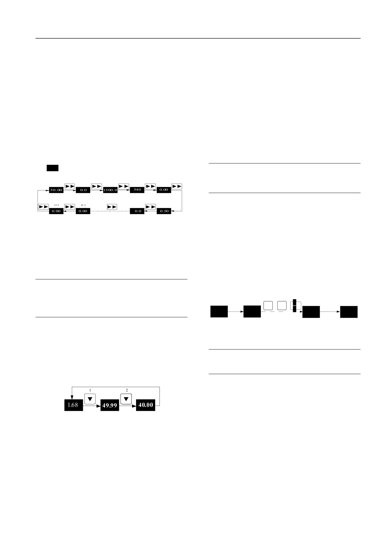
Example 4: Adjust Setting Frequency of Ordinary
1.Press MENU/ESC key under locking state of servo drive.
Operation
LED will enter password verification status 0000.
2.Modify the 0000 into 1368.
After power up of servo drive, ▼ and ▲ key may be used to
modify setting frequency.
3.Press DATA/ENTER key to ensure, the password verification
will pass. The LED displays P00.03.
Note
Operation procedures above may refer to figure below:
When the operation panel display parameters are operation
2
rotational speed, setting rotational speed , operation line
1
3
MENU
:
DATA
speed, setting line speed, press▼and▲key to modify setting
+
:
+
ESC
ENTER
50.00
0000
1368
P00.03
rotational speed or line speed value.
Frequency
Password
First class
Example: change the setting frequency from
50.00Hz to
converter
authentication
Correct password
menu
:
lock
status
Flickering bits
40.00Hz.
Figure 5-6: User password removal
Under any status of servo drive powers up (AI1 voltage displays
The servo drive may be implemented by password verification.
in the example), press▼key to modify setting frequency from
Note
(long time press may adjust rapidly)
50.00to
40.00. The
modification has finished.
After entering user passwords, the password protection will
be locked when 5 minutes no key operation.
Operation procedures above may refer to the following figure:
2.1.1.3.
Example 7: Locking Operation Panel
No button operation in 5 second
Automatic return to the initial state
The operation panel may be locked by function P00.06. The
specific refer to 6.1.1 system management (P00 group).
Example: locking all keys of operation panel
AI1 voltage
Given frequency
Goal setting
display status
changes state.
fast blink
1.Under stop parameter status displayed, press MENU/ESC key
Note: bold numbers in figure indicate the flashing digit
to enter A-level menu P00.00.
Figure 5-5: setting frequency
2.Press ▲key to select function code P00.06.
After modification, the LED will return to AI1 voltage display
3.Press DATA/ENTER key to enter B level menu.
status
(display status before modify) after
5 seconds of no
4.Press XX key, select hundred of digits.
operation.
5.Press ▲ key to modify hundred from 0 to 1.
Example 5: Switch Operation Command Channel
6.Press DATA/ENTER key to ensure and return to A-level
Before operation, the P00.06 shall be set as xx1x
(stop
menu.
switching effective) or xx2x
(stop, operation switching
effective).
37
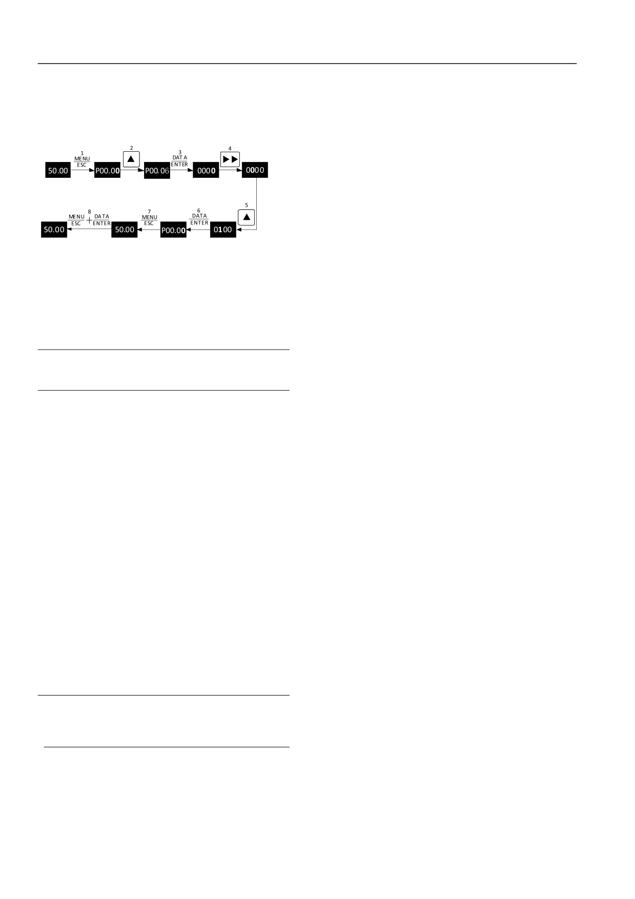
Chapter VI Function Code Details
7.Press MENU/ESC key to return to stop parameter display
1.Stop status: after initialization of servo drive powers up, the
state.
servo drive will enter stop status when: no operation
8.Press DATA/ENTER key and keep, then press MENU/ESC
command input; implement stop command in operation.
key to lock operation panel.
2.Operation status: after receive operation command. The servo
The procedures above may refer to figure below:
drive will enter operation status.
3.Motor parameter auto-tuning status: operation command
sends after function parameter P03.11 (or P04.11) sets as 1 or 2,
Stop parameter
First class
Second class
the motor parameter identification status will be entered. After
display state
menu
menu
Flickering bits
Flickering bits
identification, the stop status will be entered.
5.2.3Servo Drive Control and Operation Mode
Stop parameter
First class
Operation
Control Mode
panel button
display state
menu
lock
Flickering bits
HSD2000 servo drive has 4 control types which determined by
Figure 5-7: operation panel key lock
function code P02.00.
Example 8: Unlock Operation Panel Key
1.No PG vector control: zero speed sensors without installation
of PG. At the same time, the high control performance is
When all the operation panel keys are locked, the following
equipped to control speed and torque of motor accurately. The
operation may be implemented to unlock: press DATA/ENTER
low frequency high torque and high speed accuracy may
key and keep, then click▼key for three times.
achieve high accuracy torque control and speed control. It may
Note
be used in fields of no meeting V/F control mode and high
However setting of P00.06, the operation panel shall be
robustness requirements.
unlock status after servo drive powers up.
2.PG vector control: the PG shall be installed to ensure the
control performance is installed on controlled motor shaft. It is
applicable for fields of faster torque response and higher torque
5.2Servo Drive Operation Mode
and speed control accuracy. As feedback, the PG may finish
In the following chapters, terminologies of servo control,
high accuracy position control—servo control function.
operation and status will be referred. Please read the chapter
3.No PG V/Control: it is used for fields: lower requirements for
carefully to understand and use the following functions.
normal performance requirements; single servo drive controls
multi motors.
5.2.1Servo Drive Operation Command Channel
4.PG V/F control: PG shall be installed to improve V/F speed
Servo drive operation command channel specifies servo drive to
control accuracy.
accept operation command: physical channels in start and stop,
2.1.1.4.
Operation Mode
jog. The operation command channels include three types:
1.Operation panel: control by RUN, STOP and JOG keys of
Operation modes of HSD2000 servo drive vector control
operation panel.
include the following three types:
1.Speed control: Control motor speed accuracy. Related
2.Control terminal: control by control terminal FWD, REV,
COM (Two-wire), Xi (Three-wire).
function code of P07 and P08 groups shall be configured.
2.Torque control: Control torque speed accuracy. Related
3.Serial port: control start and stop by upper computer.
function code of P07 and P08 groups shall be configured.
The command channel shall be selected by function code
P02.02, LOCAL key and DATA/ENTER key of operation panel,
3.Position control: it is only effective in PG vector controls.
multi-function input terminal (P10.00~P10.07 selects number
Motor position shall be controlled accuracy to achieve motor
27-29 functions).
position synchronous function. The P09 group function code
shall be set.
Note
HSD2000 servo drive supports online switch of the operation
Before switch command channel, the switch debugging
modes.
shall be implemented. Otherwise equipments damage and
personal injury will be occurred!
5.2.2Servo Drive Run Status
HSD2000 run status include stop status, operation status, motor
parameter auto-tuning status.
38
Chapter VI Function Code Details
5.2.4Servo Drive Frequency, Torque, Position Given
Operation modes of HSD2000 servo drive in speed control
include 5 types. According to priority, the order shall be: jog
Channel
operation, process closed-loop operation, PLC operation,
1.Frequency Given Channel under Speed Control Mode
multi-segment speed operation and common operation. As
shown in figure below:
Power on
stopped state
Speed control
mode
Jog command
Inching run
ConnLevel_
High
Closed loop setting up effective
Closed loop failure
terminal closure?
Closed run
Valid place
Failure terminal
closed:
run
Multistage frequency
Multistage speed
terminal effective?
operation
Priority
Common run
Low
Figure 5-8: speed control mode
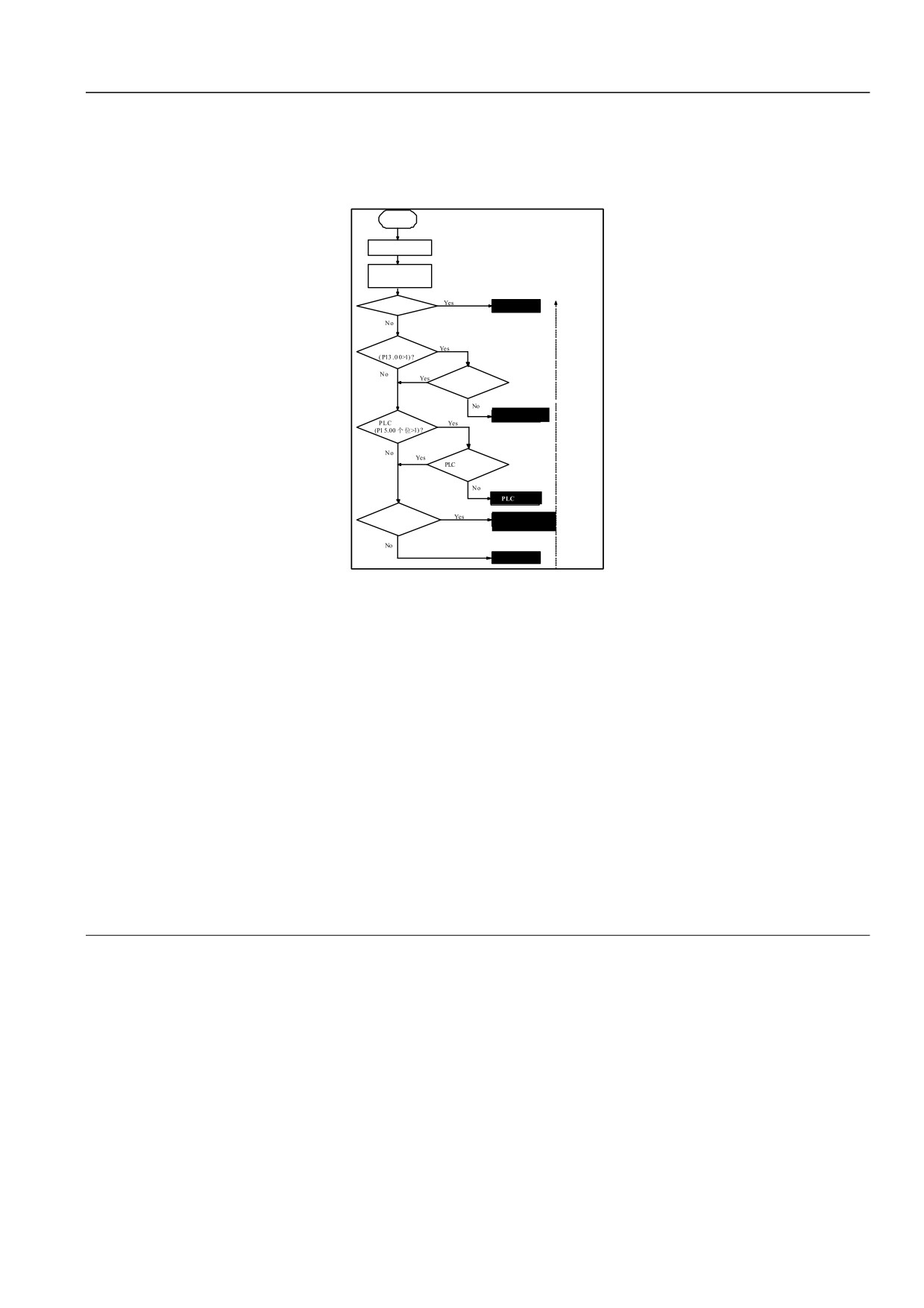
5 operation modes may provide 5 basic frequency sources. In addition to “jog operation” frequency, other 4 frequency sources may
implement auxiliary frequency overlay, frequency adjustment. The “PLC operation”, “multi-segment operation”, “ordinary operation”
shall be adjusted by swing frequency. The operation modes details are shown below:
1) Jog operation: when servo drive receives jog operation command (such as press operation panel JOG key) in stop status, operation
may follow jog frequency (see function code P02.16, P02.17~P02.19).
2) Process closed-loop operation: the process closed-loop selection function is effective (P13.00=1). Servo drive will select process
closed-loop operation mode. The closed-loop shall be adjusted as given and feedback values (see P13 group function code). The
multi-function terminal (number-21 function) may be used to fail process closed-loop operation mode. It shall be switched to lower
degree operation mode.
3) PLC operation: PLC function selection is effective (P15.00 unit is not 0). Servo drive will select PLC operation mode. The servo drive
will be operated as pre-set operating mode (see P15 function code description). The multi-function terminal (number-22 function) may be
used to fail process closed-loop operation mode. It shall be switched to lower degree operation mode.
4) Multi-segment speed operation: according to ON / OFF combination of multi-function terminal (number 1, 2, 3, 4 function), the
multi-segment frequency1~15 (P16.00~P16.14) shall be selected to implement multi-speed operation. Three terminals shall not in OFF
status. Otherwise it will be ordinary operation mode.
Note:
For specific given channel of operation mode frequency in speed control mode, see chapter VI of function code detailed decryption:
2.Torque Given Channel under Torque Control Mode
HSD2000 is equipped with 4 torque given channels in torque control mode:
1) AI analog given
2) Terminal PULSE given
3) Serial port communication given
4) Process closed-loop output
For specific, refer to P08 group function code detailed description of function code detailed introduction in chapter VI.
3.Position instruction given source under position control mode
39