HSD2000 Series Servo Drive. Operation Manual V1.2 - page 1
HSD2000 Series Servo Drive
Operation Manual
V1.2
Content
Chapter I Safety Information
5
1.1 Safety Precaution
5
1.2 Precautions
6
Chapter II Product Introduction
8
2.1. General Specification
8
2.2. Product Serial Introduction
9
2.2.1. HSD2000 Servo Drive Model
9
2.2.2. HSD2000 Servo Drive Serial Model and Nameplate
10
2.3. Dimension and Gross Weight
11
2.3.1. Dimension and Net Weight of Servo Drive
11
2.3.2. Operation Panel and Installation Box Dimension
13
2.4. Optional Accessories
13
2.4.1. Braking Resistor and Brake Unit Option Recommendation
14
2.4.2. Expanded PG Card Introduction
16
Chapter III Installation Environment and Part Disassembly
18
3.1 Servo Drive Installation Environment
18
Chapter IV Servo Drive Connection and EMC Installation Instructions
20
4.1Main Circuit Terminal Connection and Configuration
20
4.1.1 Main Circuit Input and Output Terminal Type
20
4.1.2Connect servo drive and optional accessories
21
4.1.3Basic Operation Connection Connection
22
4.2Control Circuit Connection and Configuration
22
4.2.1Relative position and function introduction of jumper
22
4.2.2Control circuit terminal wiring
23
4.3Optional Accessories Installation
29
4.2Installation Instructions Met EMC Requirement
29
4.4.1Noise Suppression
29
4.4.2Site Connection Requirement
31
4.4.3Ground
31
4.4.4 Installation Requirements of Relay, Contactor and Electromagnetic Brake
32
4.4.5Leakage Current and Strategies
32
4.4.6Correct EMC Installation of Servo Drive
32
4.4.7Power Supply Wave Filter User Guide
33
4.4.8Servo Drive Radiation Emission
33
Chapter V Servo Drive Rapid Operation Guide
35
5.1Servo Drive Operation Panel
35
5.1.1Operation Panel Appearance and Key Function Description
35
5.1.2LED Digital and Indicator Description
36
5.1.3Operation Mode of Operation Panel
36
5.2Servo Drive Operation Mode
38
2
5.2.1Servo Drive Operation Command Channel
38
5.2.2Servo Drive Run Status
38
5.2.3Servo Drive Control and Operation Mode
38
5.2.4Servo Drive Frequency, Torque, Position Given Channel
39
5.3The First Power up
40
5.3.1Checking before Power up
40
5.3.2The First Power Up Operation
40
5.4Pilot running
41
5.4.1 Sensorless Vector Pilot Running
41
5.4.2Closed-loop Vector Pilot Running
41
5.4.3Torque Control Pilot Running
41
5.4.4Servo Control Pilot Running(X7 and X8 terminal pulse serial control as example)
41
5.4.5Spindle Positioning Pilot Running
42
5.4.6Synchronous Motor Pilot Running(Increment ABZUVW Encoder as Example)
42
Chapter VI Function Code Details
43
6.1 Function Code Description
43
6.1.1System management (P00 group)
43
6.1.2Status Display Parameter (P01 group)
45
6.1.3Basic Operation Parameter
(P02 group)
47
6.1.4 Motor 1 parameter (P03 group)
50
6.1.5 Motor 2 parameter
(P04 group)
53
6.1.6Start and Stop Parameter
(P05 group)
55
6.1.7V/F Control Parameter
(P06 group)
57
6.1.8Speed Control Parameter (P07 group)
58
6.1.9Torque Control Parameter
(P08 group)
60
6.1.10 Servo control parameters (P09 group)
63
6.1.11 Switch I/O terminal parameters (P10 group)
65
6.1.12 Analog I/O terminal parameters (P11 group)
77
6.1.13 Encoder parameters (P12 group)
83
6.1.14 Process closed loop parameters (P13 group)
84
6.1.15 Extended function code parameters (P14 group)
88
6.1.16 Simple PLC parameters (P15 group)
93
6.1.17 Multi-speed parameters (P16 group)
96
6.1.18 LED display parameters (P17 group)
97
6.1.19 Communication parameters (P18 group)
98
6.1.20 Bus communication parameters (P19 group)
99
6.1.21 Protection parameter and fault record (P20 group)
99
6.1.22 Traverse operation parameter (P30 group)
103
6.1.23 Driver parameters (P97 group)
107
6.1.24 Custom parameter group (P98 group)
107
Chapter VII Measures relative Fault Alarm, Handling of Abnormality
108
Chapter VIII Servicing and Maintenance
114
8.1 Daily servicing and maintenance
114
8.2 Regular maintenance
114
3
8.3 Replacement of quick-wear parts of servo driver
115
8.4 Storage of servo driver
115
8.5 Maintenance of servo driver
115
Chapter IX Functional Code List
116
Appendix I: Communication Protocol
162
1. Networking mode
162
2. Interface
162
3. Communication
162
4. Protocol format
162
5. Protocol function
163
6. Servo driver’s control parameters and status parameters
167
7. Expansion access
171
8. Precautions
173
9. CRC Check
175
10. Application Samples
176
11. Servo driver’s calibration relation
177
4
Chapter I Safety Information
Electrical personnel construction may prevent electric shock!
Breaker shall be used for separation between servo drive and
Chapter I Safety Information
power to prevent fire!
Before wiring, power shall be ensured shutdown to prevent
electric shock!
Safety Definitions
Ground terminal shall be grounded to prevent electric shock!
Safety precaution in the manual is divided into the
following two parts:
Attention
The power line shall be not connected to output terminal U, V, W
Danger
to prevent servo drive damage!
The connection path shall be ensured to meet EMC requirements
No required operation will cause serious injuries or
and related safety standard. The used conductor diameter shall
even death.
refer to manual recommendation to prevent accident!
The braking resistor shall be not connected between
+ and
-terminal of DC bus, otherwise it may cause fire!
Before power up:
Attention
No required operation will cause moderate, minor
injury or equipments damage.
Danger
The power voltage degree shall be ensured to be consisted with
1.1
Safety Precaution
servo drive rated voltage. The input and output wiring position
Before installation:
shall be correct. Inspect for short circuit of peripheral circuits and
circuit fastening to prevent servo drive damage!
Servo drive shall not power up before cover the plate. Otherwise
Danger
the electric shock will be occurred!
Damage and servo drive lacking parts servo drive will cause
injury!
Above B degree insulated motor shall be used to prevent electric
Attention
shock!
Servo drive does not need to implement withstand test. The test
In installation:
has been implemented before factory. Otherwise the accident
would be occurred.
All the peripheral accessories shall be wired as circuit provided by
Danger
the manual. Otherwise the accident would be occurred!
Please install to flame retardant objects to get away from
After power up:
combustibles.
Otherwise, the fire alarm will be occurred.
Danger
Cover plate shall be not opened after power up. Otherwise the
Attention
electric shock will be occurred!
When two or more servo drives are placed in the same cabinet, the
Don’t touch servo or surround circuit by wet hands. Otherwise
installation position (refer to chapter III in installation) shall be
electric shock will be occurred!
noted to ensure cooling effects.
Don’t touch servo drive terminals (including control terminal).
Conductor head or screw shall not fall into servo drive to prevent
Otherwise electric shock will be occurred!
servo drive damage!
At the beginning of power up, servo drive would inspect external
strong electrical circuit automatically. At this time, U, V, W
In connection:
wiring terminals shall be not touched to prevent electric shock!
Danger
5
Chapter I Safety Information
Attention
parameters shall be adjusted; or the thermal relay shall be
During parameter identification (if necessary), be careful to the
assembly in front of motor to protect motor.
rotary motor for hurt someone. Otherwise it will cause accidents!
Operation above power frequency
Don’t changing servo drive factory parameter freely. Otherwise
The servo drive may provide 0Hz~1000Hz output frequency.
the equipments will be damaged!
When operate in greater than
50Hz condition, tolerance of
In operation:
mechanical device shall be considered.
Machinery vibration
Servo drive may meet mechanical resonance points of loading
Danger
device in certain output frequency. The mechanical resonance
points may be avoided by setting servo drive inside jump
When select restart function, we shall not close to mechanical
frequency parameters.
equipments to prevent personal injury!
Motor heat and noise
Don’t touch cooling fan and discharge resistor. Otherwise burn
injury will be occurred.
Since the servo drive output voltage (PWM wave) contains certain
harmonic wave; the motor temperature, noise and vibration are
The signal in operation shall be inspected by professionals.
greater than power frequency.
Otherwise personal injury or equipment damage would be
occurred.
Output end contains voltage dependent devices or electric
capacity (improve power factor)
Servo drive output is PWM wave. When electric capacity of
improving power factor or lightning voltage dependent resistors is
Attention
installed, servo drive instantaneous over current or servo drive
During servo drive operation, the dust shall be avoided to fall into
damage will be caused.
equipments. Otherwise equipments damage will be occurred!
When the servo drive installs contactor, the contactor shall be not
Start and stop of servo drive shall be not controlled by contactor
used to control start and stop of servo drive. If necessary, the
on and off. Otherwise equipments damage will be occurred!
interval of contactor controlling servo drive starting and stop shall
be not less than one hour. Charging or discharging frequently will
In maintenance:
reduce electric capacity service life in servo drive. When the
contactors install between output end and motor, on-off operation
of servo drive shall be implemented in no output. Otherwise
module in servo drive will be damaged.
Danger
Using other than rated voltage
The equipments shall be not maintained or repaired by electric.
The servo drive shall be not used in other than manual allowance
Otherwise electric shock will be occurred!
working voltage range. Otherwise parts of servo drive will be
After ten minutes of power cut, servo drive may be maintained
damaged. If necessary, related pressure lifting or relief device
and repaired when positive or negative bus terminal voltage is less
shall be used in pressure treatment.
than 36V. Otherwise the residual charge will hurt people!
Three-phase input changes into two-phase input
Maintenance shall be implemented by professionals. Otherwise
Three-phase servo drive of the serial shall be not changed into
personal injury or equipment damage would be occurred!
two-phase. Otherwise servo drive fault or damage will be caused.
Lightning surge protection
1.2
Precautions
The serial servo drive is equipped with over current protective
device. The device is equipped with certain ability for
Motor insulation inspection
self-protection in lighting. For lightning occurs frequently,
Motor insulation inspection shall be implemented in: before reuse
customers shall install protection in front of servo drive.
of primary placing at long time; regular inspection. The insulation
Altitude height and derating using
inspection will prevent servo drive from damage caused by motor
winding insulation fault. During insulation inspection, the motor
In area of higher than 1000M of thin air, the cooling effects will
wire will be separated from servo drive. The 200V voltage mega
be worse. The derating using will be implemented. If applicable,
meter is suggested to use. The measured insulation resistor shall
consult our company.
be not less than 5TΩ.
Special using
Motor thermal protection
During using, if customers need to use methods other than wiring
When rated capacity of selected motor is different from servo
diagram of the manual (such as common DC bus), please consult
drive, especially when the servo drive rated power is greater than
to our company.
motor rated power. The servo drive inside motor related
Servo drive scrapped precautions
6
Chapter I Safety Information
1) Electrolysis electric capacity in servo drive will be exposed in
burning.
2) Plastics, Rubber on servo drive will generate hazardous, toxic
gas in burning. Be careful in burning.
3) Treat servo drive as industrial waste
Adaptive motor
1) The standard adaptive motor shall be four-grade squirrel-cage
asynchronous induction motor. If not the motor above, the motor
rated current shall be applied to select servo drive. When drive the
PMSM, please consult to our company.
2) Cooling fan and rotor shaft of non-inverter motor are connected
in the same shaft. The fan cooling effects will reduce when
rotational speed reduces. Thus the motor overheating may install
fan or change into inviter motor.
3) Servo drive has set adaptive motor standard parameters inside.
According to specified, the parameter identification or
personalized defaults shall be implemented to conform actual
value as much as possible. Otherwise operation effects and
protective performance will be influenced.
4) Since short circuit of cable or motor will cause servo drive
alarms or explosion, the insulation short circuit testing will be
implemented to primary installation motor and cable. The testing
may be implemented in daily maintenance. During the testing,
servo drive and tested part shall be broken.
Before operating the servo drive, please read the
manual carefully. The contents shall be learned to
operate correctly.
The manual is attachment configured with machine.
After using, it shall be saved carefully for view at any
time.
7
Chapter II Product Introduction
Chapter II Product Introduction
The chapter shows basic products information of HSD2000 serial products specification, model and structure.
2.1. General Specification
Table 2-1Common Specification
Item
Item description
Rated voltage;
Input
Three-phase, 380V~480V; 50Hz/60Hz; voltage unbalance rate: <3%; frequency: ±5%
frequency
Rated frequency
380V, 400V, 415V, 440V, 460V, 480V
Output
Frequency
0Hz~1000Hz
Overload
G: 150% rated current in 2 minutes,200% rated current 0.5 seconds
magnetic flux vector control without PG(SVC), magnetic flux vector control with PG(VC), servo control, V/F
Control mode
control, V/F control with PG
Modulation mode
Space vector PWM modulation
Speed range
1: 200 (magnetic flux vector control without PG), 1: 5000 (magnetic flux vector control with PG, servo control)
150% rated torque@0Hz (magnetic flux vector control without PG), 200% rated torque@0Hz (magnetic flux
Start torque
vector control with PG)
Operational
rotational speed
±0.2% rated synchronous speed (magnetic flux vector control without PG),
steady-status
±0.02% rated synchronous speed (magnetic flux vector control with PG, servo control)
accuracy
±0.3% rated synchronous speed (magnetic flux vector control without PG)
Speed fluctuations
±0.1% rated synchronous speed (magnetic flux vector control with PG、servo control)
Positioning
±1 pulse
accuracy
10ms (magnetic flux vector control with PG, servo control);
Torque response
Main control
20ms (magnetic flux vector control without PG)
performance
Torque control
Support magnetic flux vector control without PG, magnetic flux vector control with PG, servo control
Frequency accuracy
Digital setting: maximum frequency×±0.01%; analog setting: maximum frequency×±0.2%
Frequency
Digital setting: 0.01Hz; analog setting: maximum frequency×0.05%
resolution
Torque boost
Automatic torque boost, manual torque boost 0.1%~30.0%
V/F curve
Four types: one user setting V/F curve and 3 reduced torque curves (2.0 order, 1.7 order, 1.2 order)
Acceleration and
Two types: linear acceleration and deceleration, S curve acceleration and deceleration; Four Acc/Dec time, Time
deceleration curves
units (minutes / seconds) optional, maximum to 60 hours
Initial frequency of DC injection braking process: 0.00 Hz~60.00Hz; Braking time: 0.0s~30.0s; Braking
DC braking
current: 0.0%~100.0%
Automatic Voltage
When grid voltage changes, the output voltage keeps constant automatically.
Regulation (AVR)
Automatic current
Limit current in operation automatically to prevent overcurrent fault tripping frequently.
limiting
Automatic carrier
According to loading characteristics, the carrier wave frequency may be adjusted automatically; optional
wave adjustment
Textile traverse
Textile traverse frequency control, achieve adjustable traverse frequency function of center frequency
frequency
Free bundling and synchronous switching may be implemented between command channel and given frequency
Bundling function
channel.
Customization
Jog frequency range: 0.00Hz~50.00Hz;Jog acceleration and deceleration time 0.1s~60.0s may best; jog
Jog
capabilities
interval can be set
Multi-speed
Multi-speed operation will be achieved by inside PLC or control terminals.
operation
built-in process
Form closed loop control system
closed loop control
Operation
Operation
Operation panel control , terminal control, Sci control, and may be switched by variety of methods.
function
command channel
8
Chapter II Product Introduction
Item
Item description
Given frequency
Digital given, analog voltage, analog current, pulse, serial port may be switched by variety of methods.
channel
Given auxiliary
Achieve flexible auxiliary frequency fine tuning, frequency synthesis
frequency
Pulse output
0~100kHz pulse signal output, achieve output of setting frequency, output frequency.
termianl
Analog output
2analog signals output, 0/4~20mA or 0/2~10V may be selected separately. Achieve output of setting
terminal
frequency, output frequency.
LED display
Display 20 types of parameters such as setting frequency, output frequency, output voltage and output current .
LCD dislay
Optional, Chinese / English prompts content
operation
Parameter copy
Operation panel may be used to achieve rapid copy of parameters
panel
Key lock and
Achieve parts or all locking functions pf keys. Define function range of part key to prevent error operation.
function selection
lack-phase protection (optional) , over current protection, over voltage protection, under-voltage protection,
Protective function
over-thermal protection, overload protection, off-load protection
Condition
Indoor, without sunlight, dust, corrosive gases, flammable gas, mist, water vapor, dripping or salt.
Environme
Altitude height
Derating above 1000 meters, derating 10% in each 1000 meters lifting
nt
Ambient temperature
-10℃~+40℃ (ambient temperature between 40℃~50℃, derating )
Humidity
5%~95%RH, without condensing
Environme
Vibration
Less than 5.9m/s2 (0.6g)
nt
Storage temperature
-40℃~+70℃
Protective degree
IP20
Structure
Cooling method
Air-cooled with fan control
2.2. Product Serial Introduction
2.2.1. HSD2000 Servo Drive Model
Table 2-2 Servo Drive serial
Rated output current
Servo drive model
Rated capacity (KVA)
Rated input current (A)
Adaptive motor
(kW)
(A)
HSD2000-4T-1R5
3.0
5.0
3.7
1.5
HSD2000-4T-2R2
4.0
5.8
5.0
2.2
HSD2000-4T-004
6.3
10.0
9.0
4
HSD2000-4T-5R5
8.5
15.5
13.0
5.5
HSD2000-4T-7R5
11.0
20.5
17.0
7.5
HSD2000-4T-011
17.0
26.0
25.0
11
HSD2000-4T-015
21.0
35.0
32.0
15
HSD2000-4T-018
24.0
38.5
37.0
18.5
HSD2000-4T-022
30.0
46.5
45.0
22
HSD2000-4T-030
40.0
62.0
60.0
30
HSD2000-4T-037
50.0
76.0
75.0
37
HSD2000-4T-045
60.0
92.0
90.0
45
HSD2000-4T-055
72.0
113.0
110.0
55
HSD2000-4T-075
100.0
157.0
152.0
75
HSD2000-4T-090
116.0
180.0
176.0
90
HSD2000-4T-110
138.0
214.0
210.0
110
HSD2000-4T-132
167.0
256.0
253.0
132
HSD2000-4T-160
200.0
307.0
304.0
160
HSD2000-4T-185
230.0
355.0
350.0
185
HSD2000-4T-200
250.0
385.0
380.0
200
HSD2000-4T-220
280.0
430.0
426.0
220
HSD2000-4T-250
309.0
488.0
470.0
250
HSD2000-4T-280
342.0
525.0
520.0
280
HSD2000-4T-315
388.0
605.0
590.0
315
9
Chapter II Product Introduction
HSD2000-4T-355
427.0
667.0
650.0
355
HSD2000-4T-400
454.0
701.0
690.0
400
HSD2000-4T-450
510.0
789.0
775.0
450
HSD2000-4T-500
566.0
877.0
860.0
500
HSD2000-4T-560
625.0
982.0
950.0
560
HSD2000-4T-630
724.0
1184.0
1100.0
630
HSD2000-4T-800
921.0
1500.0
1400.0
800
2.2.2. HSD2000 Servo Drive Serial Model and Nameplate
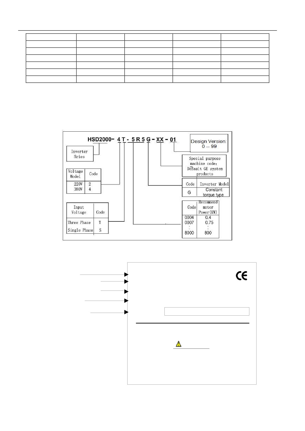
HSD2000 servo drive models description is shown in figure 2-1. The nameplate description is shown in figure 2-2.
Figure 2-1 HSD2000 Servo Drive Nameplate
Inverter Model
MODEL HSD 2000 -4 T -5R5 G- TE - 02
Adaptation motor capacity
POWER: 5.5 kW
Rated input voltage curent
INPUT:
3 PH AC 380-440 V 15.5A 50/60 HZ
and frenquency
Rated current and
OUTPUT :3 PH AC0 - 440 V 13A 0~1000HZ
frequency range
Barcode information
S/ N :
WARNING
* Risk of electric shock
* Wait 10 mins power down before removing cover
* Read the manual and follow the safety instructiongs
before use
Figure 2-2 HSD2000 Servo Drive Model
10
Chapter II Product Introduction
2.3. Dimension and Gross Weight
2.3.1. Dimension and Net Weight of Servo Drive
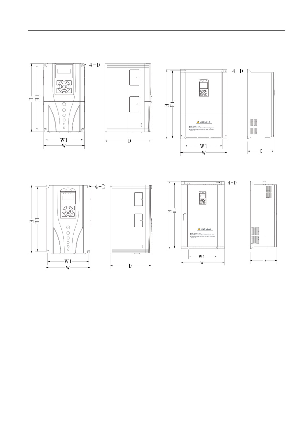
Dimension of servo drive is shown as figure below:
Figure 2-3 HSD2000-4T-1R5~HSD2000-4T-7R5
Figure 2-5 HSD2000-4T-018~HSD2000-4T-055
Figure 2-4 HSD2000-4T-011~HSD2000-4T-015
Figure 2-6 HSD2000-4T-075~HSD2000-4T-280
11
Chapter II Product Introduction
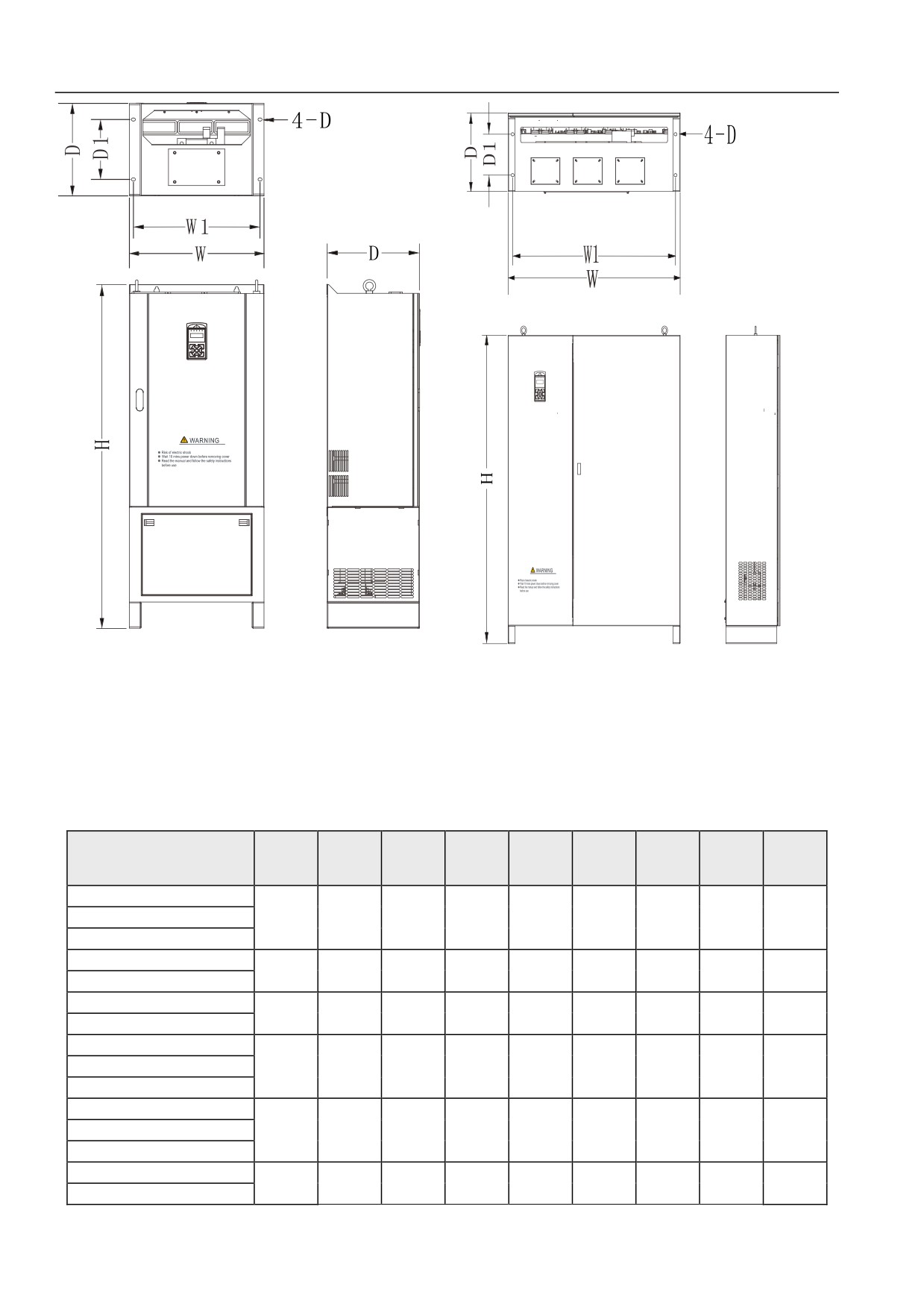
Figure 2-7 HSD2000-4T-315~HSD2000-4T-560
Figure 2-8 HSD2000-4T-630~4T-800
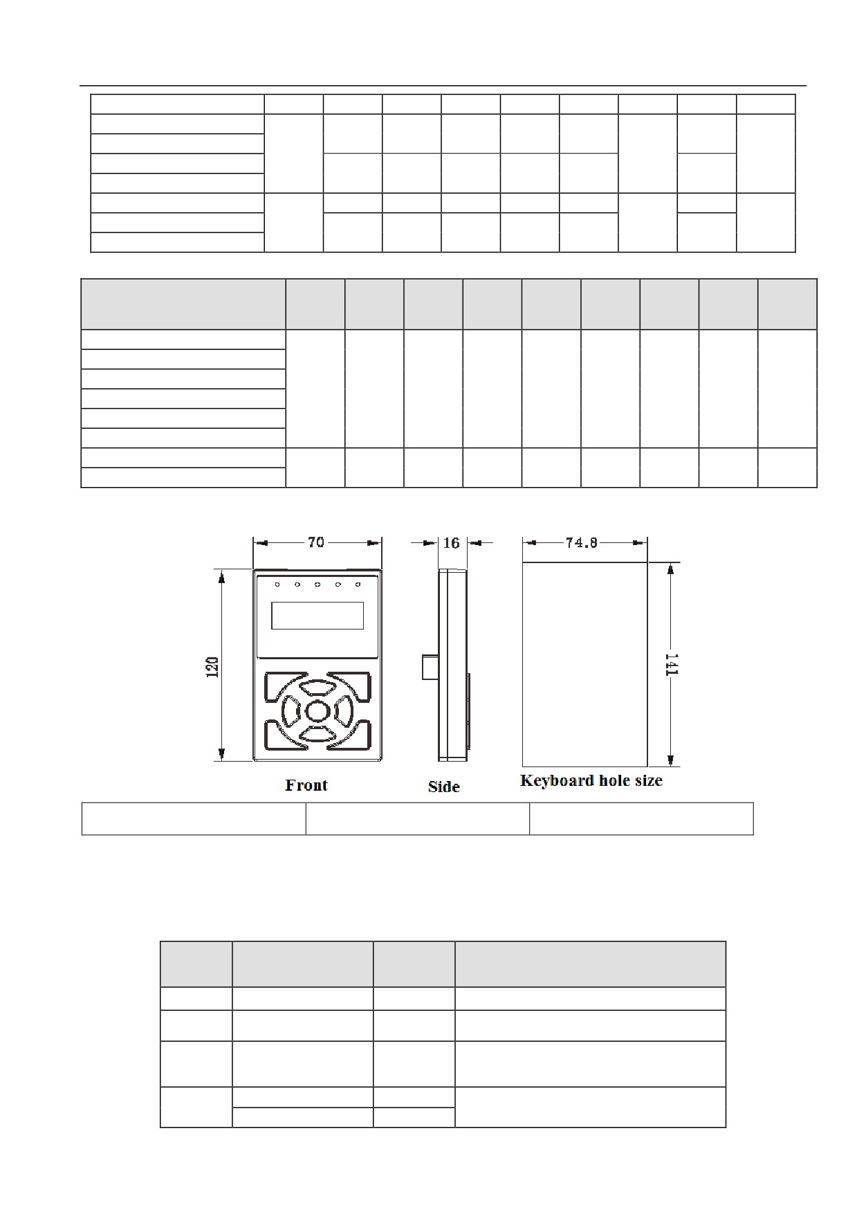
Table 2-3 HSD2000 Serial Servo Drive Dimension table 1 (mm)
Outline
Installatio
Gross
Installation
Servo drive model
D
W1
H1
H
W
Drawing
n hole
weight
method
No.
diameter
(kg)
HSD2000-4T-1R5
HSD2000-4T-2R2
175
127
200
215
140
Figure2-3
5
3.5
Hanging
HSD2000-4T-004
HSD2000-4T-5R5
181
146
251
262
157
Figure2-3
5.5
5
Hanging
HSD2000-4T-7R5
HSD2000-4T-011
181
180
288
305
198
Figure2-4
5.5
8
Hanging
HSD2000-4T-015
HSD2000-4T-018
HSD2000-4T-022
220
230
424.5
438
276
Figure2-5
7.0
18
Hanging
HSD2000-4T-030
HSD2000-4T-037
HSD2000-4T-045
231.5
320
571
589
395
Figure2-5
10.0
45
Hanging
HSD2000-4T-055
HSD2000-4T-075
298
320
733
759
489
Figure2-6
12.0
75
Hanging
HSD2000-4T-090
12
Chapter II Product Introduction
HSD2000-4T-110
HSD2000-4T-132
320
898
927
539
Figure2-6
125
Hanging
HSD2000-4T-160
370
12.0
and
HSD2000-4T-185
507
898
1377
539
Figure2-6
142
cabinet
HSD2000-4T-200
HSD2000-4T-220
280
1022
1054
704
Figure2-6
160
Hanging
HSD2000-4T-250
373
12.0
and
672
1022
1500
704
Figure2-6
181
HSD2000-4T-280
cabinet
Table 2-4 HSD2000 Serial Servo Drive Dimension table 2 (mm)
Servo Drive Model
Shape
Hole
Estimated
Installatio
(G: constant torque loading; P: fan pump
D
W1
D1
H
W
Figure No.
diameter
weight (kg)
n means
loading)
HSD2000-4T-315
HSD2000-4T-355
HSD2000-4T-400
400
924
240
1684
960
Figure2-7
14.0
365
Cabinet
HSD2000-4T-450
HSD2000-4T-500
HSD2000-4T-560
HSD2000-4T-630
460
1386
240
1808
1464
Figure2-8
18.0
*
Cabinet
HSD2000-4T-800
2.3.2. Operation Panel and Installation Box Dimension
Front
Side
Keyboard hole size
Figure2.9 Keyboard Appearance and Installation Dimension
2.4. Optional Accessories
The following optional accessories may be ordered to our company (if necessary)
Remark
Accessories
Option range
Specification
name
Brake unit
See table 2-4
See table 2-4
Keyboard
Option
74.7×141
Hole size
tray
Keyboard
extension
Option
2m、3m
Network cable
cable
132KW~200KW option
539*370*485
132KW~280KW installation may be compatible
Cabinet base
220KW~280KW option
704*366*480
hanging with cabinet
13
Chapter II Product Introduction
Remark
Accessories
Option range
Specification
name
DC reactor
132KW~800KW option
-
-
2.4.1. Braking Resistor and Brake Unit Option Recommendation
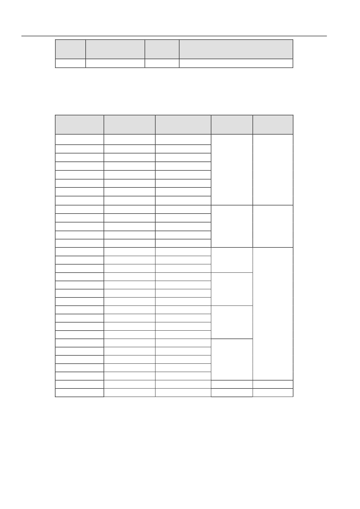
Energy consumption braking requirements, braking resistor or braking unit may refer to table 2-4. Braking resistor wiring specification,
wiring specification between brake unit and servo drive may refer to table 3-2.
Table 2-4 Braking Resistor and Brake Unit Option Recommendation Table
Braking Resistor
Brake Unit
Braking Resistor
Servo Drive Model
Recommended
Recommended
Remark
Recommended Power
Resistor Value
Model
HSD2000-4T-1R5
200-300Ω
200W
HSD2000-4T-2R2
100-250Ω
250W
HSD2000-4T-004
100-150Ω
300W
Built-in
HSD2000-4T-5R5
80-100Ω
500W
Standard
HSD2000-4T-7R5
60-80Ω
700W
Configuration
HSD2000-4T-011
40-50Ω
1.0KW
HSD2000-4T-015
30-40Ω
1.5KW
HSD2000-4T-018
25-30Ω
2.0KW
HSD2000-4T-022
20-25Ω
2.5KW
Built-in
HSD2000-4T-030
15-20Ω
3.0KW
3.5KW
Standard
HSD2000-4T-037
15-20Ω
HSD2000-4T-045
10-15Ω
4.5KW
Configuration
HSD2000-4T-055
10-15Ω
5.5KW
HSD2000-4T-075
8~10Ω
7.5 KW
HSD2000-4T-090
BU4R150
8~10Ω
9 .0KW
HSD2000-4T-110
6~8Ω
11 .0KW
HSD2000-4T-132
6~8Ω
13.5KW
HSD2000-4T-160
4~6Ω
16 .0KW
BU4R250
HSD2000-4T-185
4~6Ω
18.5 KW
HSD2000-4T-200
4~6Ω
20.0 KW
External
HSD2000-4T-220
6~8*2Ω
11.0*2 KW
HSD2000-4T-250
6~8*2Ω
12.5*2 KW
option
BU4R250*2
HSD2000-4T-280
4~6*2Ω
14*2 KW
HSD2000-4T-315
4~6*2Ω
16*2 KW
HSD2000-4T-355
4~6*3Ω
11*3 KW
HSD2000-4T-400
4~6*3Ω
14*3 KW
HSD2000-4T-450
4~6*3Ω
17*3 KW
BU4R250*3
HSD2000-4T-500
4~6*3Ω
21*3 KW
HSD2000-4T-560
4~6*3Ω
25*3 KW
HSD2000-4T-630
HSD2000-4T-800
Note: Resistance value and power of braking resistor shall be not less than recommended minimum resistance and power of table
above. Otherwise the brake unit will damage.
Attached: braking resistor calculation method
In braking, almost all renewable energy of motor consumes on the braking resistor. Where:
U×U/R=Pb
U-Brake voltage of system table brake (U value is different in different systems, 380Vac system takes 700V);
Pb - Brake power
Braking resistor power selection
14
Chapter II Product Introduction
In theory, braking resistor power is consisted with braking power. Considering 70% of derating, where:
0.7×Pr=Pb×D
Pr -Resistor power;
D -Braking frequency, percentage between renewable process and overall process.
Common applications, elevator, uncoiling and reel, centrifuge, accidental braking load, general situation
common
Uncoiling
Accidental
General
Elevator
Centrifuge
applications
and reel
braking load
situation
Braking
20%
20 ~30%
50%~60%
5%
10%
frequency value
~30%
Table 2-4 shows the guide data. Users may select different resistance value and powers as actual situation. (Resistance shall be not less
than recommended value in table, power may be greater.) Braking resistor selection shall be ensured by motor power in actual applicable
system. The braking resistor is related with system inertia, deceleration time and potential energy load. It shall be selected by actual
situation of customers. The greater of system inertia, the shorter of the deceleration time, the more frequent braking. The greater of braking
resistor selected power, the smaller of resistance value.
15
Chapter II
Product Introduction
2.4.2. Expanded PG Card Introduction
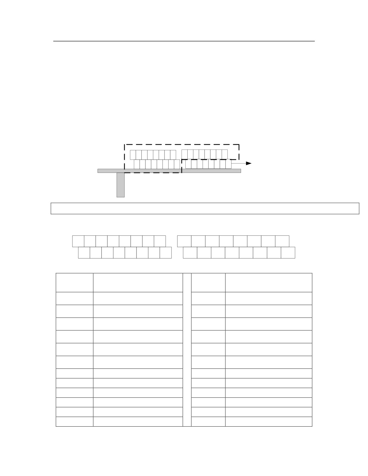
Function Introduction
1.Encoder interface PG1, support differential ABZ and UVW signal as speed feedback or position feedback.
2.PG1 pulse frequency division output is used for speed or position synchronization.
3.PG2 is used for pulse reference interface. Pulse instruction may be received from external device. The
instruction may be used for speed or position synchronization.
Terminal Introduction
PG Card Side Figure is shown below:
PG
1
U
V
W
PG
A
B
Z
2
Slot connected with
control plate
Slot connected with control plate
PG1 and PG2 terminal arrange are shown below:
U+
U-
V+
V-
W+
W-
5V
GND
PAO+
PAO-
PBO+
PBO-
PZO+
PZO-
5V
GND
A+
A-
B+
B-
Z+
Z-
GND
PE
2A+
2A-
2B+
2B-
2Z+
2Z-
GND
PE
The terminal function description is shown below:
Terminal
Terminal
Signal description
Signal description
name
name
A+
Encoder A signal
PAO+
Encoder frequency division
output
PAO+
A-
Encoder A-signal
PAO-
Encoder frequency division
output
PAO-
Encoder B+signal
Encoder frequency division
output
B+
PBO+
PBO+
Encoder B-signal
Encoder frequency division
output
B-
PBO-
PBO-
Encoder Z+signal
Encoder frequency division
output
Z+
PZO+
PZO+
Z-
Encoder Z-signal
PZO-
Encoder frequency division
output
PZO-
U+
Encoder U+signal
2A+
Pulse instruction A+
U-
Encoder U-signal
2A-
Pulse instruction A-
V+
Encoder V+signal
2B+
Pulse instruction B+
V-
Encoder V-signal
2B-
Pulse instruction B-
W+
Encoder W+signal
2Z+
Pulse instruction Z+
W-
Encoder W-signal
2Z-
Pulse instruction Z-
16
Chapter II
Product Introduction
5V
5V output
5V
5V output
GND
Ground
GND
Ground
PE
Shielding layer
PE
Shielding layer
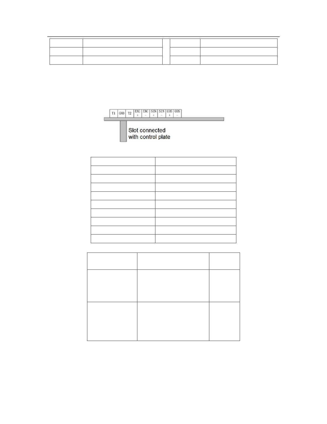
Resolver PG card function introduced
If the user selects the rotating transformer as feedback speed, should choose Resolver PG card . Resolver PG card
profile drawing is shown below :
For the detail of terminal blocks, please see the table below:
Signal screen printing
Signal definitions
T1
Motor temperature detection 1
GND
Ground
T2
Motor temperature detection 2
EXC+
Rotary Transformer REF+ Signal l
EXC-
Rotary Transformer REF - Signal
SIN+
Rotary Transformer SIN + Signal
SIN-
Rotary Transformer SIN - Signal
COS+
Rotary Transformer COS + Signal
COS-
Rotary Transformer C0S - Signal
Dial switch description:
Factory
Signal screen printing
Functional Description
value
Pole number selection:
HX1
00:×1
HX2
11
01:×2
( Move it up is 1 Move
10:×3
it down is 0 )
11:×4
Rotary transformer excitation
HF1
signal frequency selection:
HF2
00:10KHz
00
( Move it up is 1
01:2.5KHz
Move it down is 0 )
10:5KHz
11:5KHz
Fault indicating lamp and Failure reset instruction:
When the rotating transformer signal abnormalities, PG card fault indicator will light up, at this time can use SW6 fault
reset button.
17
Chapter III Installation Environment and Part Disassembly
Chapter III Installation Environment and Part Disassembly
The chapter shows installation environment requirements and parts disassembly methods of servo drive.
3.1 Servo Drive Installation Environment
It shall be installed indoor and good ventilated with vertical installation.
The following shall be noted in selecting installation environment:
Ambient temperature shall be -10℃~40℃. When the temperature is greater than 40℃, external forced cooling or derating shall be
implemented.
z
When temperature requires lower than 95%, no condensation;
z
Install in fields of less than 5.9m/s2 (0.6g) vibration;
z
Direct sunlight fields are avoided in installation;
z
Servo drive is usually installed in cabinet to prevent unauthorized personnel touch. The pollution degree shall be no worse than grade
2 of IEC60664-1.
z
When without cabinet, the servo drive shall be installed in limit area of no unauthorized personnel touch. The pollution degree shall
be no worse than grade 2 of IEC60664-1.
The special installation requirements shall be consulted and ensured before.
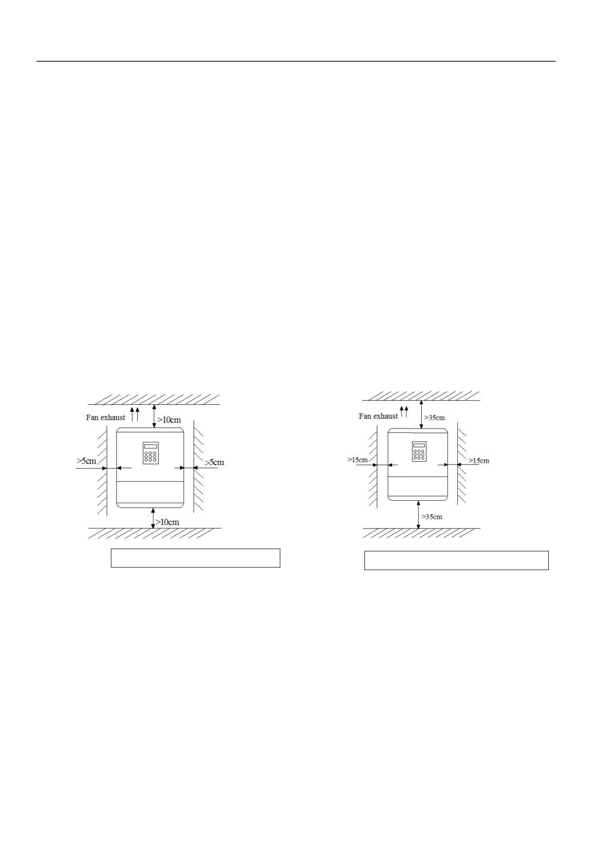
Installation interval and distance requirements are shown as Figure3-1 and Figure3-2.
Fan exhaust
Fan exhaust
Figure 3-1 Installation Interval Distance (55kW and lower)
Figure 3-2 Installation Interval Distance (75kW and lower)
18
Chapter III Installation Environment and Part Disassembly
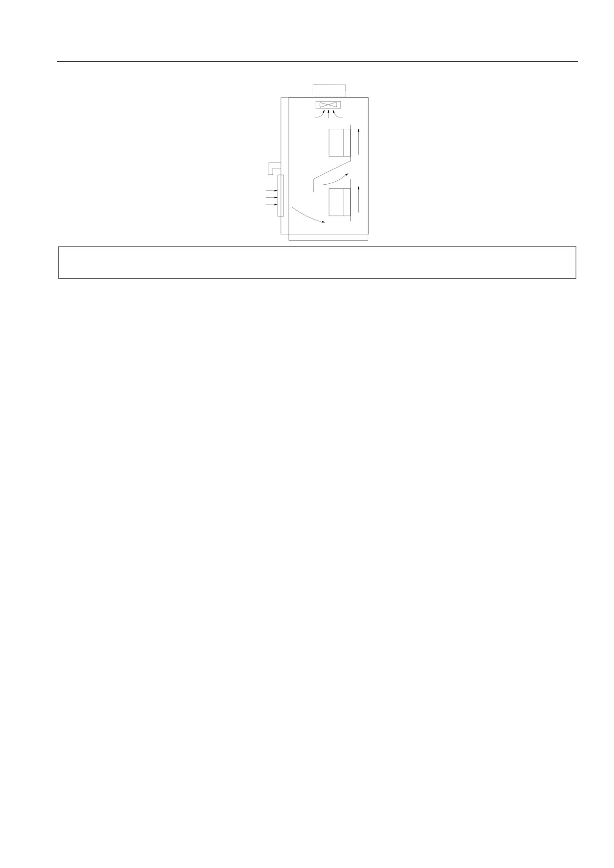
When install two servo drives, baffle plate shall be used in the middle. It is shown in Figure3-3.
Servo
motor
Servo
motor
Servo drive
Servo drive
Figure 3-3 Installation of two servo drives
19
//////////////////////