HSD2000 Series Servo Drive. Operation Manual V1.2 - page 4
Chapter VI Function Code Details
2: Reserved
OS Action Detection
Speed limit channel:
0: deceleration stops
0: By the function code P07.11 or P07.12 setting value as the
Servo drive shall as deceleration time stop.
speed limit value torque control. by function code P07.11. or
1: freewheel, report E035.
1: By the analog input terminal the value speed limit value as the
Servo drive will terminate output, motor stops according to
torque control. AI corresponding velocity relationship, set by the
mechanical inertia, and reported OS fault E035.
P11 group AI curve. Users need to define AI terminal
2: Continue to run.
functionality for speed limit value, to AI1, for example, set
OS detection does not work, servo drive continues to run.
function code P11.01 = 4 (or 5), a detailed description of the
setting method, see P11 group.
Overspeed (OS) detection value
Speed limit value
Set value of 100% corresponds to the servo drive's maximum
It is effective in P07.09
(or P07.10) =0. Set value of 100%
output frequency (P02.05).
corresponds to the servo drive's maximum output frequency
Note
(P02.05).
Over speed (OS) is effective in detecting non-V / F mode.
P07.13 speed deviation (DEV) when
0~2【2】
P07.19 Pre-excitation time
0~10s【0】
detection selection
P07.14 DEVdetection value
0.0%~50.0%【20.0%】
Pre-excitation magnetic field is used to build asynchronous motor
P07.15 DEVdetection time
0.0~10.0s【10.0s】
before start. Pre-excitation time
(P07.19) refers to the
pre-magnetizing time.
In vector control, the relative speed deviation value
=
(|
acceleration and deceleration after setting frequency - feedback
frequency | / servo drive's maximum output frequency) × 100%.
P07.20~P07.22
Reserved
If the relative speed of the set value deviation DEV detection time
Reserved function
(P07.15) is greater than the set continuous DEV detection value
(P07.14), the detecting operation is selected according to DEV
P07.23 weakening control
500~1200【1024】
function code P07.13.
coefficient
P07.24 the minimum value for
DEV Detection Action Option
10%~80%【10%】
a given flux
0: deceleration stops
Function code P07.23, P07.24 for a valid PG vector control
servo drive stop shall be implemented as deceleration time 。
mode. Weak magnetic curves are used in areas of weak magnetic
1: Freewheel, repost E034。
field weakening curve correction, the greater the value, the more
servo drive immediately terminate output, motor stops
stable and showed weakening curve.
according to mechanical inertia, and reported DEV deviation is
The minimum flux given value is the minimum flux value at the
too large fault (E034).
time of weakening.
2: Continue to run.
P07.25 Reserved
Reserved
DEV detected no movement, servo drive continues to run.
Reserved function
DEV Detection Value
6.1.9Torque Control Parameter
(P08 group)
Set value of 100% corresponds to the servo drive's maximum
output frequency (P02.05).
P08.00 speed /torque control mode
0、1【0】
0: speed control mode
Note
1: torque control mode
Speed deviation (DEV) detected only in the speed control
mode (P07.00 = 0) under effective.
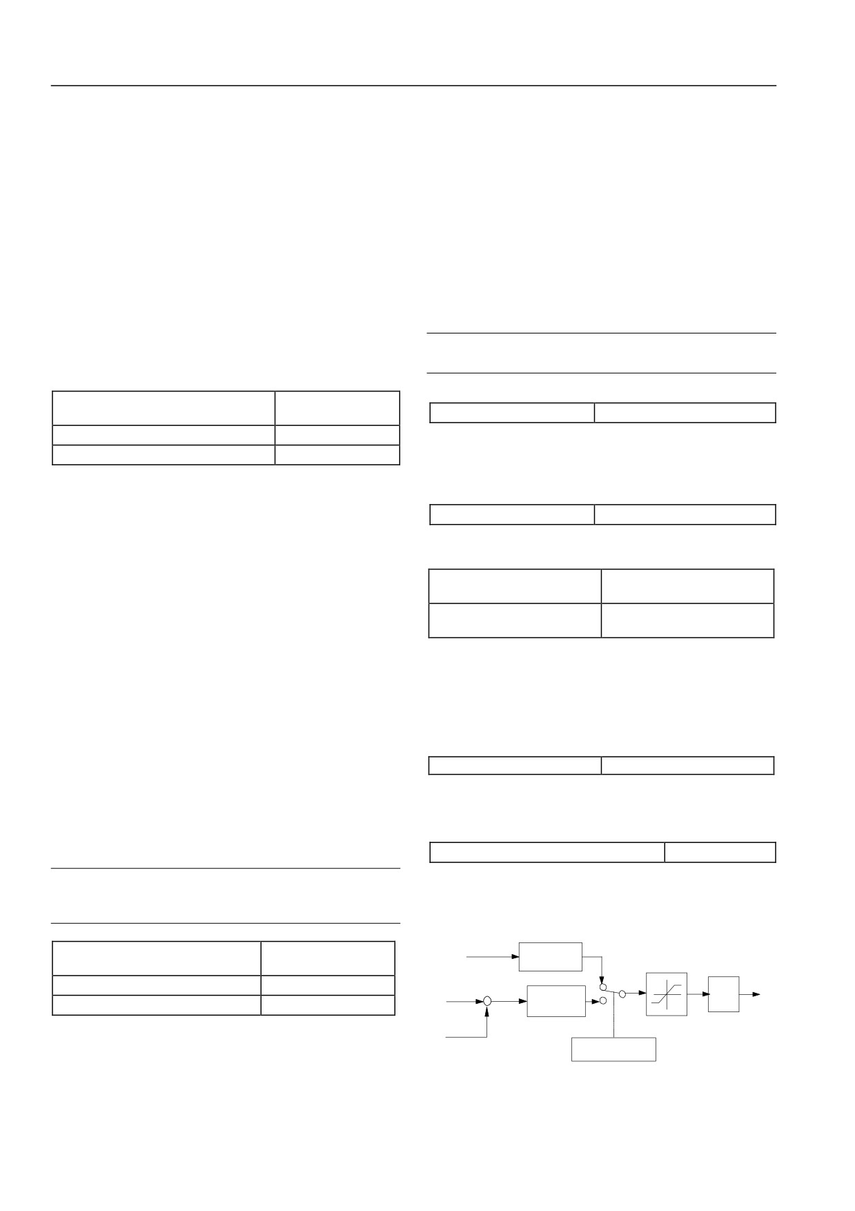
Torque control frame figure:
External torque
P07.16 overspeed (OS) when Detection
command
A time delay
0, 1, 2【1】
filter
Selection
Common
(P08.03)
d torque
P07.17 overspeed (OS) detection value
0%~130.0%【120.0%】
velocity
current
speed limit +
error
1
output filtering
KP(1+
)
P07.18 overspeed (OS) detection value
0.0s~2.00s【0.0s】
TS
i
-
actual
ASR
P08.10 P0
)
(P07.03: P07.06)
Relative velocity = (| feedback frequency | / maximum output
speed
frequency) × 100%.
actual
< speed limit
speed
If the relative speed of the set detection time OS (P07.18) is
greater than the set continuous OS detection value (P07.17), the
Figure 6-24: Moment control Figure
detection operation is selected in accordance OS function code
P07.16.
60
Chapter VI Function Code Details
Set terminal X1 ~ X8 will feature 54. You can switch the speed
switch point
【100%】
and torque control.
P08.05 speed torque
0~1000ms【0】
switch delay
P08.01 torque instruction option
0~1【0】
In torque control mode from the machine, the first for speed run,
when outputtorque achieve torque switch point P08.04, after
0: torque given
speed torque switch delay time P08.05, then cut to the torque
The given value shall represent torque percentage.
control mode.
1: torque current given
P08.05 for the torque, rotational speed control mode switches
To quantify the percentage of torque current size, torque current
delay time.
and torque given differ in weakening area.
Note
P08.02 torque given option
0~4【0】
1.For control terminalX1 ~ X8 conduct speed / torque switch,
This feature sets the torque control is given physical channel.
one set function code P10.00 ~ P10.07 to 54, and set the
0: torque instruction is set by analog terminal AI.
current control method is vector control.
AI input voltage / current of the maximum value (10V/20mA)
2.In the PLC, process closed-loop, multi-speed operation,
corresponding to 300% of the rated torque, and torque AI input
such as a special speed control mode, you can not switch to the
correspondence between specific instructions, see the P11 group,
torque control.
AI input corresponding to the positive and negative of the positive
3.When inputstop command, if the torque current control
and negative torque instruction value.
mode, then automatically switch to control the speed, and then
stop.
Users when using this feature, you need to define AI terminal
P08.06 torque limit mode
0~3【3】
function as torque instruction given to AI1, for example, set the
function code P11.01 = 8, the detailed settings see description P11
0: Restriction is invalid, only the flow
group.
According to P20.15 (servo drive automatically limiting level) for
1: torque instruction is determined by terminal PULSE.
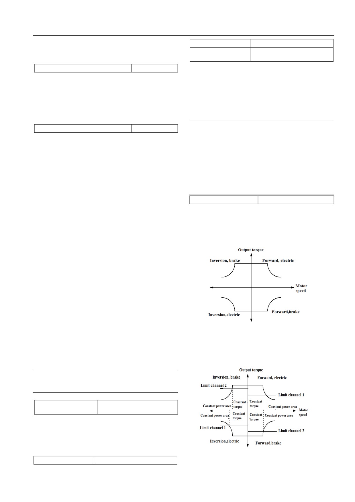
limiting, set torque limit channel (P08.07, P08.08 and P08.09).
Terminal PULSE input frequency the maximum value
Out of torque and rotational speed capability relationship
as
corresponds to 300% of rated torque instruction, correspondence
follows:
between specific pulseinput and torque, refer to the description of
P11 group, terminalPULSE given based on pulse center of choice
(P10.14) input positive and negative torque instruction value.
2: torque instruction is set by communication
PC servo drive built-in shall be implemented by standard RS485
communication port. Set the current torque instruction servo
drive.
Specific programming methods, methods of operation,
communication protocols, etc., see the MODBUS protocol.
3: torque instruction is determined by process closed-loop output
given.
1: Torque limit
Process closed-loop output as a torque instruction given. For
specific process closed-loop description of the setting method, you
According to the set torque limiter value (set by the P08.07 ~
can see P13 group.
P08.11) of torque limit, then the servo drive output current still
P20.15 (servo drive automatically limiting level) limit.
4: Reserved
Note
Motor output torque of direction, and the direction set by the
negative decision torque instruction (P02.20) irrelevant.
P08.03 torque given wave
0~65535ms【0】
filter time
By torque given channel, the external torque instruction through
delayed wave filter filtering. Setting appropriate filter time
(P08.03), the torque instruction can be prevented mutations cause
motor jitter.
P08.04 speed →torque
0.0%~+300% initial torque
Torque limit value 1, 2 is set by function code P08.07~P08.11.
61
Chapter VI Function Code Details
2: Detailed instruction Reserved
P08.11 torque limit
0.0%~300.0% initial torque 【180.0%】
value 2
3: Torque current limit
Torque limit value only P08.08 (or P08.09) = 0 is valid. Set the
According to the set torque current limiter value
(set by the
value of 100% corresponds to the servo drive's rated torque.
P08.07 ~ P08.11) of torque limit, and a torque limit mode is
basically the same, but differ in the field weakening. At this point,
P08.12 mechanical loss
-20.0%~+20.0%【0.0%】
servo drive output current still P20.15 (servo drive automatically
compensation value
limiting level) limit.
Set the mechanical loss compensation value, under speed control
and torque control for torque compensated according to the setting
P08.07 torque limit channel
0~3【1】
option
value.
Channel option of torque limit value.
Usually when a large torque loss caused by the mechanical loss of
motor mechanical losses should be adjusted, generally do not need
0: Limit value is taken from the same channel 1 and 4 quadrants
to set the value.
1: Electric (1 and 3 quadrant) taken from Channel 1, power (2 and
Set value of 100% corresponds to the servo drive's rated torque
4 quadrant) taken from Channel 2
current. Set value of 100% corresponds to the servo drive's rated
2: Upper limit (1, 2 quadrant) taken from channel 1, lower limit
torque current.
(3, 4) taken from Channel 2 upper limit.
3: The same four quadrants, limiting the choice of channel 1 and 2
by the terminal switch. Terminal function shall select 56.
P08.13 torque deviation
-300%~+300.0%【0.0%】
T1
P08.14 torque deviation
P08.08 torque limit
-300%~+300.0%【0.0%】
0~3【0】
T2
channel 1
P08.15 torque deviation
P08.09 torque limit
-300%~+300.0%【0.0%】
0~3【0】
T3
channel 2
To startup torque deviation, choose two control terminal, defined
its function as a torque deviation options to control terminalX6,
Set torque limit physical channel.
0: torque limit value by the digital setting
X7, for example, set P10.05 = 58, P10.06 = 59. By combining X6
and X7terminal can only choose one torque deviation effective,
P08.10, P08.11 as the torque limit value 1 and 2
specific parameters see table 6-2.
1: Torque limit value given by the AI
Torque Deviation Option Table
AI input voltage / current of the maximum value (10V/20mA) can
correspond to 300% of rated torque instruction, correspondence
X7
X6
Torque Deviation Option
OFF
OFF
No startup
between specific Input and output volume, see instructions P11
OFF
ON
T1
group.
ON
OFF
T2
Users when using this feature, you need to define A terminal
ON
ON
T3
function as torque limit value, to AI1, for example, set function
Set value of 100% corresponds to the servo drive's rated torque
code P11.01 = 6 (or 7), detailed settings, see instructions P11
current.
group.
2: torque limit value is given by terminal PULSE
Note
Terminal PULSE input frequency of the maximum value (100k)
Torque deviation may be effective in speed or torque control
mode.
may correspond to
300% of rated torque instruction,
correspondence between the amount of specific pulse input and
output instructions, please refer to P11 parameter group.
P08.16 torque deviation
0.0~1.0s【0.0s】
startup delay
Torque limit value pulse input terminal X8 only valid, should be
After the torque deviation effective, if P08.16 is not zero, then
defined as the torque limit function X8terminal pulse, users need
torque deviation is not immediately given the added torque, but
to set function code P10.07 = 61 or 62.
after a certain delay time (P08.16) coupled to a torque current
3: Process closed-loop output
given on.
Process closed-loop output shall be as a torque limit given. Set
the relevant process closed-loop function code may be seen in
Note
section 6.1.14 P13 group function code instructions.
Torque deviation startup delay P08.16 only AI given time to be
effective in torque deviation.
Note
Torque limit value can only be a positive value, if the setting
P08.17 over torque / less torque
value is negative value, automatically limit is 0.
0~8【0】
Detection selection
P08.18 over torque / less torque
0%~300%【0】
P08.10 torque limit
detection value 1
0.0%~300.0% initial torque 【180.0%】
value 1
P08.19 over torque / torque detection
0~10s【0】
62
Chapter VI Function Code Details
time of less than 1
By switching terminalY1 or Y2 can be monitored through the
P08.20 over torque / less torque
torque / less torque signal output.
0~8【0】
Detection selection 2
Note
P08.21 over torque / less torque
0%~300%【0】
detection value 2
Over torque / less torque detection are valid in any control
P08.22 over torque / torque detection
mode.
0~10s【0】
time of less than 2
Over Torque Determination
6.1.10 Servo control parameters (P09 group)
If within the detection time (P08.19 or P08.22), continuous greater
torque detection value (P08.18 or P08.21), considered detected
P09.00 Servo control switching
0~3【0】
over torque signal.
option
Insufficient torque judge:
0: non-servo control
If the detection time (P08.19 or P08.22), continuous torque is less
Under non-servo control, position control is not available.
than the detection value
(P08.18 or P08.21), considered
1: speed/ torque←→ servo control
insufficient detected torque signal.
Current status is speed or torque control, and when switching
Over torque / less torque detection mode selection:
terminal (function 81) of servo control is valid, it switches to
0: over torque / less torque detected invalid
servo control.
Not conducted torque / insufficient torque detection
2: servo ←→ speed/torque control
1: The only consistent speed, over torque detection continues to
Current status is servo control, and when switching terminal
run after.
(function 81) of servo control is valid, it switches to speed or
Only detect whether excessive torque during constant speed
torque control.
operation, and checked out the torque servo drive continues to
3:Servo control
run.
Under servo control, position control is available and the position
2: After running over torque detection continues to run after
given source is selected by P09.03. Control mode must be set as
3: The only consistent speed, over torque detection off after only
closed loop vector control so as to select servo control.
detect whether excessive torque output during constant speed
P09.01Servo run mode option
0~2【0】
operation, and checked out the torque servo drive stops output,
0: normal run
motor coasts to stop.
It is basic position control mode and special switching of position
4: After running through the cut output torque detection
run mode is not available.
Detected in the course of the entire operation over torque after,
1: Reserved
servo drive stops output, motor coasts to stop.
2: spindle run
5: Only consistent in speed, the less continue to run after the
torque detection during constant speed operation only detect
The spindle runs first in P09.00 mode, and when the positioning
whether the lack of torque, and the lack of detectable torque, servo
terminal
(function
77) of spindle or return-to-zero terminal
drive continues to run.
(function
84) of origin is valid, the spindle is stopped in the
6: Continue to run after run less torque detection
specified position.
After the detection of insufficient torque on the entire operation
P09.02 Orientation mode of
0~1131H【0010H】
spindle
process, servo drive continues to run
Ones place: positioning zero option
7: After only a consistent speed, the lack of torque detection cut
output
0: Z-pulse positioning
Detected only during constant speed operation is insufficient
When Z-pulse is used as spindle zero, the accuracy of position
torque, and detection of the lack of torque servo drive stops output,
control is high, but the encoder must be installed on the spindle.
motor coasts to stop.
1: photoelectric switch positioning
8: Cut output after running less torque detection
The photoelectric feedback signal of a position on the spindle is
After the detection of insufficient torque on the entire operation
used as spindle zero.
process, servo drive stops output, motor coasts to stop.
Tens place: acceleration/deceleration time option
Over torque / less torque detection value:
0~3: acceleration/deceleration time option
In the V / F control mode, set the value for the corresponding
Select
acceleration/deceleration
1
~
4
as
the
servo drive rated current at 100%; in vector control mode, set the
acceleration/deceleration time of the process that spindle slows
value for the corresponding motor when 100% rated torque.
down to its directional speed.
63
Chapter VI Function Code Details
Hundreds place: motion option after the spindle is stopped in the
P09.10 Numerator of position
1~65535【1024】
specified position.
instruction ratio
P09.11 Denominator of position
0: hold at the positioning point
1~65535【1024】
instruction ratio
Continue position control and hold at the specified stop point.
1: hold within the positioning range
A pulse instruction is converted into amount of movement of
When the position deviation from the specified stop point is
motor by setting the function codes P09.10 and P09.11, e.g. a
within the range set in P09.12, position control is not available;
pulse represents 10um. It may be controlled without regard to the
when the deviation is beyond the range, a position loop is
speed reducing ratio of machinery and pulse number of encoder.
available.
An example is given below:
Thousands place: calculation mode of position
On the supposition that the encoder is of 2500 lines and absolute
0: direct position loop control
position of travel of motor completing one revolution is 5mm, it
1: position loop + feedfoward control
can be known that 5mm distance corresponds to 10000 (2500×4)
pulses.
P09.03 Position given source
0~4【0】
Now there is a workpiece that needs moving 8mm, so the number
0: X8 terminal pulse given
8
The number of X8 pulses is given as motor position. Users are
of pulses that need moving is
×10000; supposing that
5
requested to define X7 terminal function as position pulse
instruction unit is 1um, position pulse is directly set as 8000 and
direction and define X8 terminal function as position pulse input,
8
and respectively set the function codes: P10.06=71, P10.07=72.
electronic gear ratio is set as
×10000
=2 .
5
8000
1
1: Reserved
Therefore, set the function codes: P09.10=2, P09.11=1.
2: expansion PG given
P09.12 Range of positioning
1~10000【10】
Pulse input on the expansion PG card is set as motor position.
completion
3: setting of position number
In the process of servo running, if position deviation is within the
The position target of motor is set by the function codes P09.05
set range (P09.12), servo positioning is completed. If any switch
and P09.06.
output terminal function is defined as positioning completion
4: Reserved
output, take Y1 as an example, set the function code P10.18=25,
and simultaneously output a positioning completion indication
P09.04 Pulse instruction input
0~1【0】
mode option
signal.
The function code defines the expansion PG card as the pulse
P09.13 Width of position
1~32767【100】
approach signal
input mode when the position is given.
In the process of servo running, if position deviation is within the
0: A/B phase pulse
set range (P09.13), the position approaches. If any switch output
It is two-phase orthogonal pulse; when A phase is in advance of B
terminal function is defined as position approach output, take Y1
phase, motor rotates forward.
as an example, set the function code P10.18 = 26, and
1: PLUS+SIGN pulse
simultaneously output a position approach indication signal.
It is pulse + direction input mode; A phase represents pulse train
P09.14 Position out-of-tolerance
and B phase represents direction; when it is high level, motor
0~32767【1000】
detection range
rotates forward and when it is low level, motor rotates backward.
P09.15 Position out-of-tolerance
0~1【0】
P09.05 Position given- high
alarm option
0~150【0】
position
0: valid
P09.06 Position given- low
0~65535【0】
1: invalid
position
In the process of servo running, if position deviation is beyond the
When the position given source is digitally set (P09.03=3), the
set range (P09.14) and position out-of-tolerance alarm option is
function codes P09.05 and P09.06 are valid.
valid (P09.15=0), when any switch output terminal function is
P09.07
Reserved
defined as position out-of-tolerance alarm output, take Y1 as an
Reserved function
example, set the function code P10.18=28, and simultaneously
P09.08 Filtering time constant of
0~3000.0ms【10ms】
output a position out-of-tolerance alarm indication signal.
position instruction
P09.16 Spindle transmission ratio
0~30.000【1.000】
A position instruction needs to be filtered by a one-delay filter.
Filtering time constant of the filter is set by the function code
On many occasions, the spindle of spindle motor needs to be
P09.08
controlled by a transmission mechanism. The transmission ratio of
the transmission mechanism is set by P09.16.
P09.09
Reserved
Reserved function
64
Chapter VI Function Code Details
P09.17~P09.18
Reserved
Position gain can be manually switched by means of a terminal.
Reserved function
Any one of terminals X1~X8 may be selected and it is defined as
function “80”; take X3 as an example, set P10.02=80 and enable
P09.19 Directional speed of spindle
0~200.00【5.00】
X3, and after switching time of position gain passes, position gain
When motor spindle is revolving at a high speed, after spindle
will be switched to 1 from 2.
orientation is started, the spindle should be first switched to a
relatively low speed
(P09.19) from the high speed and then
P09.33 Speed feedforward gain
0~120.00%【100.00%】
positioned. The acceleration/deceleration time from current speed
P09.34 Output amplitude limit
0~100.0%maximum frequency
to directional speed is set by P09.02.
of position controller
【0.0%】
Speed
P09.20 Starting position of spindle
Calculated pulse
Position
0~30000【0】
filtering
feedforward
orientation
frequency f
gain
P09.21 Directional deceleration
(P09. 08)
(P09. 33)
0~3000.0【10.0】
Pulse given
time of spindle
+
Proportional gain KP
P09.22 Spindle position 1
0~30000【0】
Pulse
-
Speed give
feedback
(P09. 26)
P09.23 Spindle position 2
0~30000【0】
(P09. 34)
P09.24 Spindle position 3
0~30000【0】
P09.25 Spindle position 4
0~30000【0】
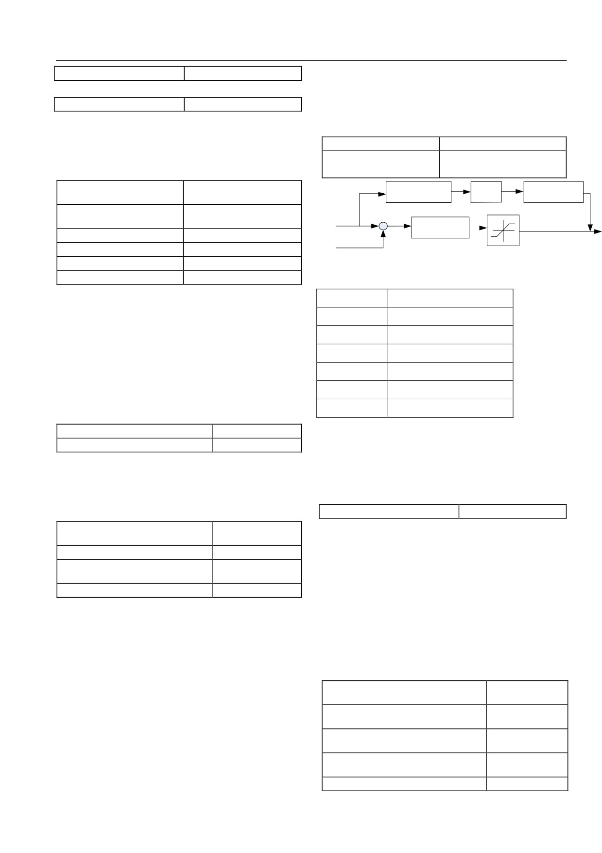
Fig. 6-25 Simplified Diagram of Servo Control with Pulse Given
After the spindle is switched to directional speed (P09.19), it runs
脉冲给定
Pulse given
at the speed and waits for orientation starting position (P09.20);
脉冲反馈
Pulse feedback
after arriving at the position, orientation starts and the spindle is
decelerated to the specified stop point according to the
计算脉冲频率 f
Calculated pulse frequency f
deceleration time set by P09.21, to make it just stop in the set
位置滤波
Position filtering
position (one of P09.22~P09.25). P09.21 refers to the time for
decelerating to zero from maximum speed.
速度前馈增益
Speed feedforward gain
The positions 1~4 can be selected by means of terminals; for
比例增益 KP
Proportional gain KP
details, see the description of functions “78” and “79” in the P10
速度给定
Speed given
group.
In the servo control mode, when the position given source is pulse
P09.26 Position loop gain 1
1~8000【50】
given at a certain frequency, position feedforward control is
P09.27 Position loop gain 2
1~8000【200】
required to ensure feedback can quickly track the given pulse.
Proportional gain of position loop regulator is set by P09.26 and
Output amplitude limit of position controller:
P09.27. The greater the gain is, the quicker the position tracking is,
When set value is 100%, it corresponds to maximum output
but too great gain may easily cause oscillation; the smaller the
frequency of servo driver (P02.05).
gain is, the slower the position tracking is. Position gain should be
increased properly while it does not cause oscillation.
P09.35 Servo stop mode
0~1【0】
P09.28 Switching mode of position gain 1
In the process of servo control, a stop mode may be selected by
0~4【0】
and gain 2
P09.35.
P09.29~P09.30
Reserved
0: Emergency stop by torque limit
P09.31 Level of position gain switching
0~10000
The frequency of servo driver immediately reduces to 0 according
deviation
to the instruction and servo driver stops in an emergency.
P09.32 Smoothing time of gain switching
0~100ms
1: Stop by switching to speed control
Servo driver stops according to the set deceleration curve from
0: non-switching
current speed after switched to speed control mode from servo
Position loop gain 1 (P09.26) is valid.
control mode.
1: Reserved
6.1.11 Switch I/O terminal parameters (P10 group)
2: Reserved
3: Position deviation
P10.00 Function option of multi-function
0~88【0】
When position deviation is smaller than the level of position gain
input terminal X1
P10.01 Function option of multi-function
switching deviation
(P09.31), after smoothing time of gain
0~88【0】
input terminal X2
switching (P09.32) passes, position gain will be automatically
P10.02 Function option of multi-function
switched to position loop gain 1 (P09.26) from position loop gain
0~88【0】
input terminal X3
2 (P09.27).
P10.03 Function option of multi-function
0~88【0】
4: external terminal switching
input terminal X4
P10.04 Function option of multi-function
0~88【0】
65
Chapter VI Function Code Details
input terminal X5
Cont
Content
Corresponding function
Corresponding function
P10.05 Function option of multi-function
ent
0~88【0】
input terminal X6
48
Reserved
49
Reserved
Pre-exciting command
P10.06 Function option of multi-function
50
Reserved
51
0~88【0】
terminal
input terminal X7
52
Reserved
53
Reserved
P10.07 Function option of multi-function
0~88【0】
Switching terminal of speed
input terminal X8
54
55
Reserved
control and torque control
Selection of torque limitation
56
57
Reserved
channels 1 and 2
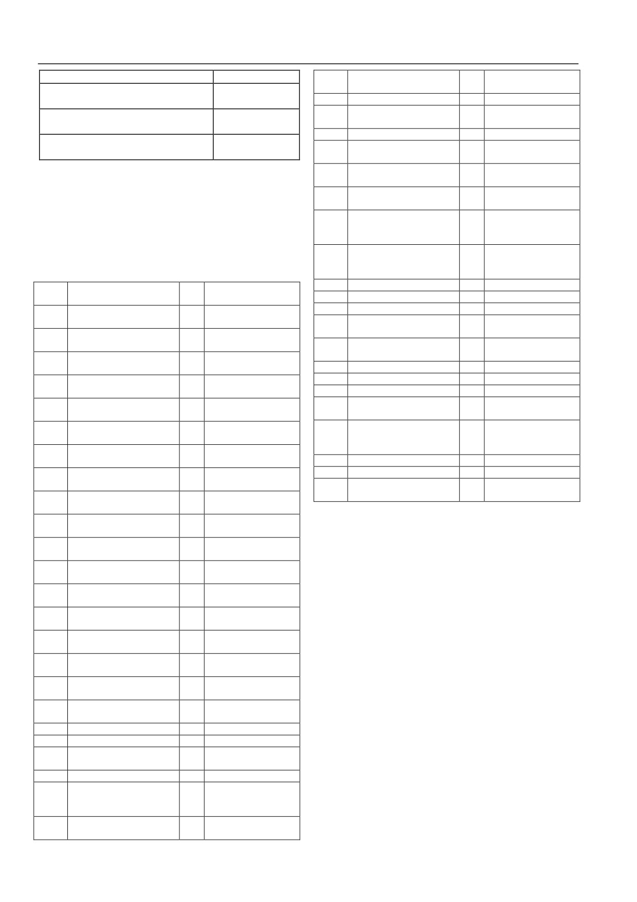
Multi-function input terminals X1~X8 are functionally rich and a
Torque-bias option
function can be selected easily according to the need, i.e. the
58
Torque-bias option terminal 1
59
terminal 2
functions of X1 ~ X8 can be defined respectively by setting
Pulse input terminal of
P10.00~P10.07 and set values and functions are as shown in
60
Torque-bias retention
61
torque limitation 1 (set
for X8 only)
table 6-3 below.
Pulse input terminal of
Pulse input terminal of torque
Table 6-3 Multi-Function Input Option Functions
62
63
torque given (set for X8
limitation 2 (set for X8 only)
only)
64
Reserved
65
Reserved
Cont
Content
Corresponding function
Corresponding function
ent
66
Reserved
67
Reserved
Multi-phase frequency
68
Reserved
69
Reserved
0
Non-function
1
terminal 1
Position pulse direction
70
Reserved
71
Multi-phase frequency
Multi-phase frequency
(only X7 is valid)
2
3
terminal 2
terminal 3
Position pulse input (only X8
Reset of position
72
73
Multi-phase frequency
Acceleration/deceleration
is valid)
deviation counter
4
5
terminal 4
time terminal 1
74
Instruction pulse disable
75
Reserved
Acceleration/deceleration time
Normally open input of
76
Reserved
77
Spindle orientation start
6
7
terminal 2
external fault
78
Position option terminal 1
79
Position option terminal 2
Normally closed input of
Servo control switching
8
9
External reset input
80
Reserved
81
external fault
terminal
Control input of external jog
Control input of external
Position reference point
10
11
forward-rotation
jog reverse-rotation
82
Reserved
83
input terminal (only
Frequency increase
X6,X7 and X8 are valid)
12
Free stop (FRS) input
13
instruction (UP)
84
Origin return-to-zero
85
Reserved
Frequency decrease
Simple PLC pause
86
Reserved
87
Reserved
14
15
instruction (DOWN)
instruction
Switching terminal of motors
88
Acceleration/deceleration
1 and 2
16
17
Three-wire run control
disable instruction
The functions listed in the above table are described as follows:
Normally open contact input
Normally closed contact
18
19
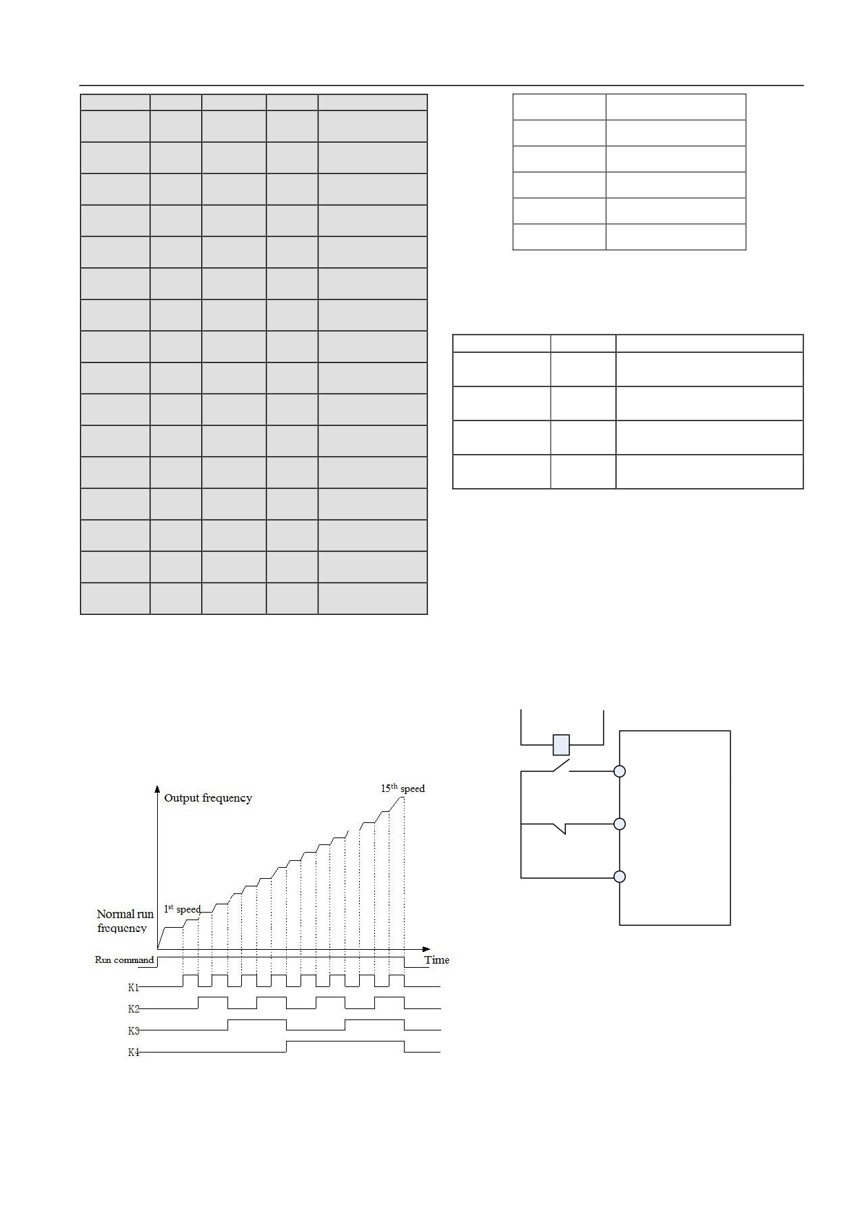
1~4: multi-phase frequency option terminals
of external interrupt
input of external interrupt
Stop DC braking input
15-phase speed running curves at most can be defined by selecting
20
21
Closed loop disable
instruction
the ON/OFF combination of these function terminals.
Main set frequency
22
PLC disable
23
Table 6-4 Selection of Multi-Speed Run
source option 1
Main set frequency source
Main set frequency
24
25
option 2
source option 3
Main set frequency switching
Command switching to
26
27
to AI
terminal
Command source option
28
Command source option 1
29
2
Multi-phase closed loop given
Multi-phase closed loop
30
31
terminal 1
given terminal 2
Multi-phase closed loop given
Multi-phase closed loop
32
33
terminal 3
given terminal 4
Traverse frequency state
34
Traverse frequency input
35
reset
36
External stop instruction
37
Servo driver run disable
38
Forward rotation disable
39
Reverse rotation disable
Reset of auxiliary set
Clearing of PLC stop
40
41
frequency
memory
42
Reserved
43
Reserved
Pulse input of main set
44
Reserved
45
frequency (set for X8
only)
Pulse input of auxiliary set
PG tach input
(set for
46
47
frequency (set for X8 only)
X8 only)
66
Chapter VI Function Code Details
K4
K3
K2
K1
Frequency setting
输出频率
Output frequency
Normal running
OFF
OFF
OFF
OFF
frequency
普通运行频率
Normal run frequency
Multi-phase
OFF
OFF
OFF
ON
运行命令
Run command
frequency 1
Multi-phase
1 速
1st speed
OFF
OFF
ON
OFF
frequency 2
15 速
15th speed
Multi-phase
OFF
OFF
ON
ON
frequency 3
时间
Time
Multi-phase
OFF
ON
OFF
OFF
frequency 4
Multi-phase
OFF
ON
OFF
ON
5~6: acceleration/deceleration time terminal option
frequency 5
Multi-phase
Table 6-5 Expression of Acceleration/Deceleration Time Option
OFF
ON
ON
OFF
frequency 6
Multi-phase
Terminal 2
Terminal 1
Acceleration/deceleration time option
OFF
ON
ON
ON
frequency 7
Acceleration time 1/ deceleration
Multi-phase
OFF
OFF
ON
OFF
OFF
OFF
time 1
frequency 8
Acceleration time 2/ deceleration
Multi-phase
OFF
ON
ON
OFF
OFF
ON
time 2
frequency 9
Acceleration time 3/ deceleration
Multi-phase
ON
OFF
ON
OFF
ON
OFF
time 3
frequency 10
Multi-phase
Acceleration time 4/ deceleration
ON
OFF
ON
ON
ON
ON
frequency 11
time 4
Multi-phase
ON
ON
OFF
OFF
Selection of acceleration/deceleration time 1~4 can be realized
frequency 12
by the ON/OFF combination of acceleration/deceleration time
Multi-phase
ON
ON
OFF
ON
terminals 1 and 2.
frequency 13
Multi-phase
7~8: normally open/normally closed input of external device
ON
ON
ON
OFF
frequency 14
fault
Multi-phase
ON
ON
ON
ON
frequency 15
A fault signal of an external device can be inputted by the terminal,
convenient for servo driver to monitor faults of external devices.
These frequencies will be used in the multi-speed run and simple
After servo driver receives a fault signal of an external device, it
PLC run. Take multi-speed run as an example to give a description
displays “E015”, namely fault alarm of the external device. The
as below:
fault signal can be inputted in a normally open or normally closed
Control terminals X1, X2, X3 and X4 are respectively defined as
way.
below: P10.00=1, P10.01=2, P10.02=3, and P10.03=4, and
then terminals X1~X4 are used to realize multi-speed run, as
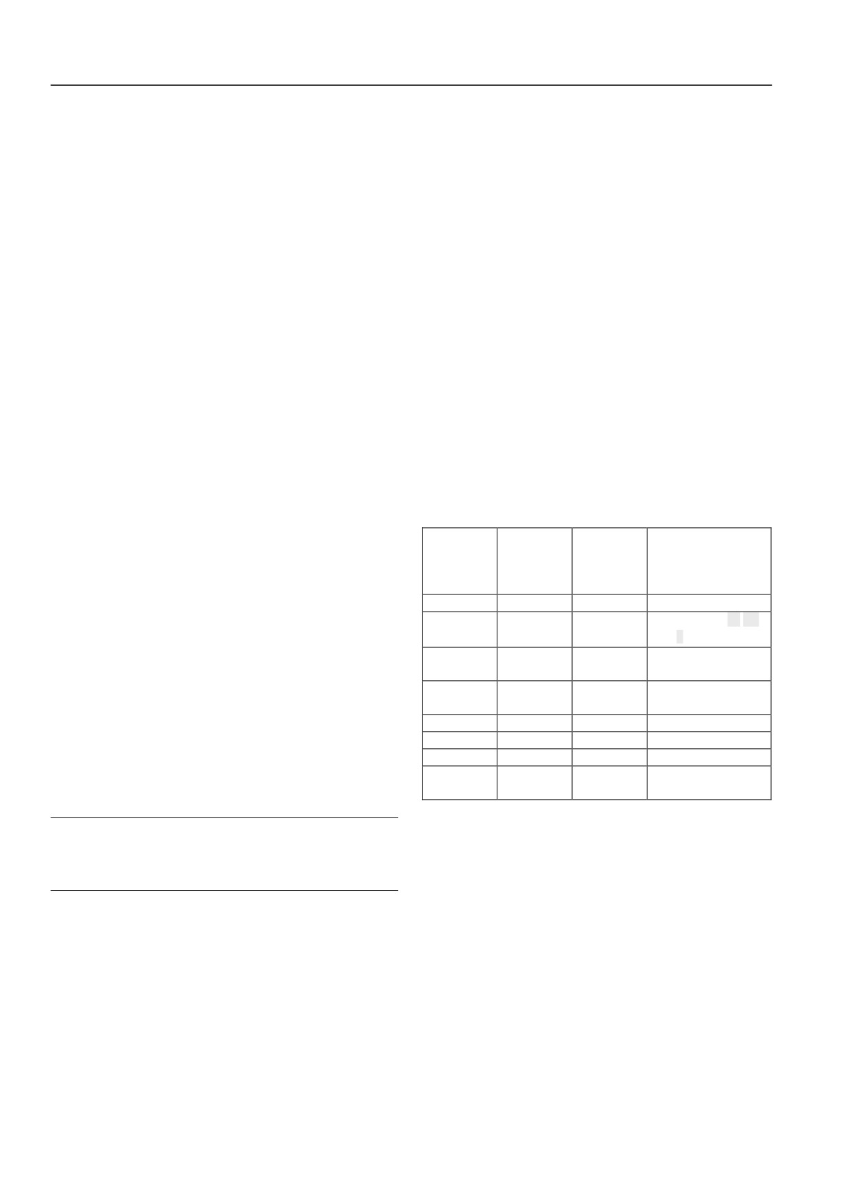
KM
shown in Fig.6-26 below:
HSD2000
Xi
Xj
COM
Fig.6-27 Normally Open/Normally Closed Input Diagram of External
Device Fault
9: external reset input
When servo driver gives a fault alarm, the fault can be reset by the
terminal. The function of the terminal is identical with the
function of RESET key on the operating panel.
10~11: control input of external jog run: JOG forward /JOG
reverse
Fig.6-26 Multi-Speed Run Diagram
67
Chapter VI Function Code Details
It is used for jog run control in the control terminal mode. Jog run
successively: setting run > jog run > closed loop run > PLC run >
frequency, jog interval time and jog acceleration/deceleration time
multi-speed run > normal run.
are defined in the P02.16~P02.19.
It can be switched between closed loop run mode and low-level
12: free stop input
run mode only in the closed loop run mode (P13.00=1).
The function is the same as the meaning of free running stop
When switched to the low-level run mode, start/stop control,
defined in the P05.05, but here is realized by a control terminal, to
direction and acceleration/deceleration time should comply with
facilitate remote control.
setting of the corresponding run mode.
13~14: frequency increase instruction (UP)/decrease instruction
22: PLC disable
(DOWN)
It is used for flexible switching between PLC run mode and
Progressive increase or progressive decrease of frequency is
low-level run mode.
realized by a control terminal, to perform remote control instead
It can be switched between PLC run mode and low-level run
of operating panel. It is valid when normal run P02.03=1, or
mode only in the PLC run mode (P15.00 Ones place ≠0).
P02.08=2 as auxiliary frequency. Increase/decrease rate is set in
When switched to the low-level run mode, start/stop control,
the P10.09 and P10.10.
direction and acceleration/deceleration time should comply with
setting of the corresponding run mode.
15: simple PLC pause instruction:
23~25: main set frequency source option 1~3
It is used for pause control of running PLC process. When the
terminal is valid, it runs at zero frequency and PLC run is not
Switching of frequency given channels in table 6-6 can be realized
timed; when the terminal is invalid, automatic speed tracking
by the ON/OFF combination of frequency given channel option
starts and PLC run continues. For the use method, refer to the
terminals 1, 2 and 3. The relation between terminal switching and
functional description of P15.00~P15.30.
setting of function code P02.03 is after-valid.
16: acceleration/deceleration disable instruction
Table 6-6 Expression of Frequency Given Channel Selection
It is used to keep motor away from any external signal influence
Option
Option
Option
(except stop command), to maintain running at current speed.
terminal 3 of
terminal 2 of
terminal 1 of
Selection of frequency
17: three-wire run control
frequency
frequency
frequency
given channel
given channel
given channel
given channel
Refer to the functional description of P10.08 run modes 2 and 3
OFF
OFF
OFF
P02.03 setting
(three-wire run modes 1 and 2).
Operating panel ▲ ▼
18~19: normally open/normally closed contact input of external
OFF
OFF
ON
given
interrupt
Terminal UP/DOWN
OFF
ON
OFF
In the running process, when servo driver receives an external
given
interrupt signal, it locks out output and runs at zero frequency.
Serial port
OFF
ON
ON
Once the external interrupt signal is cleared, automatic speed
communication given
tracking of servo driver starts and servo driver resumes running.
ON
OFF
OFF
AI analog given
ON
OFF
ON
Terminal PULSE given
External interrupt input has two modes: normally open contact
ON
ON
OFF
Extended card given
and normally closed contact. As shown in Fig.
6-27, Xi is
Frequency setting
normally open contact input and Xj is normally closed contact
ON
ON
ON
holding
input.
Attention
26: AI main set frequency switching to AI
The difference from functions 7~8 is that external interrupt
When the function terminal is valid, main set frequency channel is
will not cause alarm output of servo driver, and after interrupt
forced to switch to AI given and which AI needs to be set in the AI
signal is cleared, servo driver resumes running.
function in the P11 group. When the function terminal is invalid,
the frequency given channel will be restored to the original state.
20: stop DC braking input instruction
27: command switching to terminal
DC braking is applied to the motor in the stop process by a control
When the function terminal is valid, run command channel is
terminal, to realize its emergency stop and accurate positioning.
forced to switch to terminal run command channel. When the
Braking start frequency, braking waiting time and braking current
function terminal is invalid, run command channel will be
are defined in the P05.06~P05.08; braking time may be the
restored to the original state.
greater value between the time defined in the P05.09 and the
28~29: Command source option 1~2
effective duration of the control terminal.
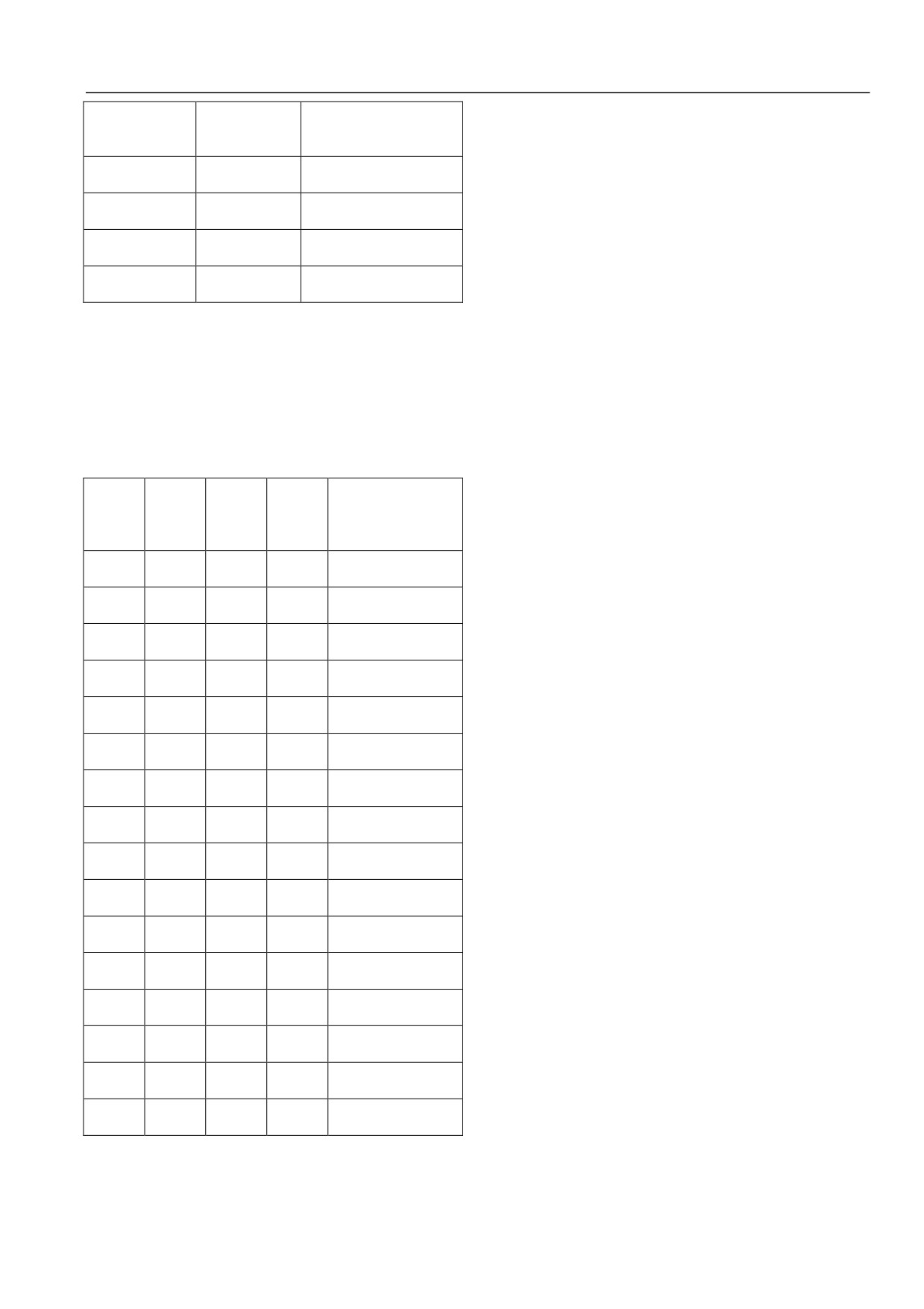
Table 6-7 Selection of Run Command Channels
21: closed loop fault
It is used for flexible switching between closed loop run mode and
low-level run mode. Run mode of HSD2000 by priority level is
68
Chapter VI Function Code Details
Option terminal 1
When traverse frequency start mode is manually put into service,
Option terminal 2 of
of command
Run command channel
the terminal is valid and traverse frequency function is valid, see
command source
source
the description of traverse frequency function parameter in the
Run command channel
OFF
OFF
P16 group.
holding
35: traverse frequency state reset
Operating panel run command
OFF
ON
channel
When selecting the traverse frequency function no matter whether
Terminal run command
it is automatic or manual mode, once the terminal is closed,
ON
OFF
channel
traverse frequency state information memorized inside servo
Serial port run command
driver will be cleared. After the terminal is disconnected, traverse
ON
ON
channel
frequency restarts. See the function description in the P16 group.
36: external stop instruction
Selection of run command channels can be realized by the
The command is valid to all run command channels. When the
ON/OFF combination of command source option terminals 1 and
function terminal is valid, servo driver will stop according to the
2.
mode set in P05.05.
30~33: multi-phase closed loop terminals 1~4
37: servo driver run disable
Table
6-8 Selection Expression of Multi-Phase Closed Loop
When the terminal is valid, running servo driver will stop freely
Given
and its start-up is disabled in the standby mode. It is mainly used
on the occasion when security interaction is required.
Multi-pha
Multi-pha
Multi-pha
Multi-pha
38: forward rotation disable
se closed
se closed
se closed
se closed
Selection of multi-phase
loop
loop
loop
loop
closed loop given
If the terminal is enabled in the process of forward rotation, servo
terminal 4
terminal 3
terminal 2
terminal 1
driver will stop freely. First enable the terminal and then run
Closed loop given
forward, and it will be in zero-frequency running state. Reverse
OFF
OFF
OFF
OFF
depends on P13.01
rotation is not affected by this.
Multi-phase closed loop
OFF
OFF
OFF
ON
39: reverse rotation disable
given 1
Multi-phase closed loop
Contrary to function 38, see the description of function 38.
OFF
OFF
ON
OFF
given 2
40: reset of auxiliary set frequency
Multi-phase closed loop
OFF
OFF
ON
ON
It is valid only to the digital auxiliary frequency (P02.08=1, 2, 3).
given 3
When the function terminal is valid, given value of auxiliary
Multi-phase closed loop
OFF
ON
OFF
OFF
given 4
frequency is reset and set frequency completely depends on main
Multi-phase closed loop
given value.
OFF
ON
OFF
ON
given 5
41: clearing of PLC stop memory
Multi-phase closed loop
OFF
ON
ON
OFF
In the stop state in PLC run mode, when the function terminal is
given 6
valid, PLC run phase, run time, run frequency and other
Multi-phase closed loop
OFF
ON
ON
ON
information of PLC stop memory will be cleared, see the function
given 7
Multi-phase closed loop
description in the P15 group.
ON
OFF
OFF
OFF
given 8
42~44: Reserved
Multi-phase closed loop
ON
OFF
OFF
ON
45: pulse input of main set frequency (set for X8 only)
given 9
It is valid only to input terminal X8, as a mode of main frequency
Multi-phase closed loop
ON
OFF
ON
OFF
given 10
setting together with P02.03=4. The relation between input signal
Multi-phase closed loop
pulse frequency and set frequency can be adjusted by curve
ON
OFF
ON
ON
given 11
setting in the P11 group.
Multi-phase closed loop
ON
ON
OFF
OFF
46: pulse input of auxiliary set frequency (set for X8 only)
given 12
Multi-phase closed loop
It is valid only to input terminal X8, as a mode of auxiliary
ON
ON
OFF
ON
given 13
frequency setting together with P02.08=5. The relation between
Multi-phase closed loop
input signal pulse frequency and set frequency can be adjusted by
ON
ON
ON
OFF
given 14
curve setting in the P03 group.
Multi-phase closed loop
ON
ON
ON
ON
47: PG tach input (set for X8 only)
given 15
It is valid only to input terminal X8 and the accuracy of speed
Selection of multi-phase closed loop given can be realized by the
control is 0.1%. The input port in combination with pulse encoder
ON/OFF combination of multi-phase closed loop terminals 1~4.
(PG) can realize feedback control of single-phase pulse speed.
34: traverse frequency input
48~50: Reserved
69
Chapter VI Function Code Details
51: pre-exciting command terminal
functions 61~63 should undergo curve adjustment in the P11
When the terminal is valid, motor pre-excitation will be started
group.
until the terminal becomes invalid.
64: Reserved
52~53: Reserved
65~70: Reserved
54: Switching of speed control and torque control
71: position pulse direction (set for X7 only)
In the vector control mode, the terminal can realize switching of
The function is valid only to terminal X7. The direction of
speed control and torque control modes. If P10.16 is set as
position pulse input depends on ON/OFF level of the terminal.
positive logic, after the terminal is closed, if output torque
72: position pulse input (set for X8 only)
(observable by P01.10) of servo driver is continuously more than
The function is valid only to terminal X8. When the terminal
switching torque point P08.04 within the set speed torque
pulse given in P09.03 is selected, the position instruction given
switching delay (P08.05), control mode will automatically switch
can be determined by inputting the pulse of the terminal.
to torque control mode; after the terminal is disconnected, it is
73: reset of position deviation counter
speed control mode. The relation between terminal switching and
setting of function code P08.00 is after-valid.
When the terminal is valid, the error count value of position given
and position feedback will be cleared.
55: Reserved
74: Instruction pulse disable
56: selection of torque limitation channels 1 and 2
When P09.03=0, 2, if instruction pulse disable terminal is valid
Selection of torque limitation channels can be realized by the
pulse input is disabled and position given remains unchanged;
terminal.
when the terminal is invalid, the pulse is inputted normally as
57: Reserved
position given.
58~59: torque-bias option terminals 1~2
75~76: Reserved
Three torque bias values can be selected by the state combination
77: spindle orientation start
of the two terminals. Torque bias values can be set by P08.13~
When spindle directional run is selected in the P09.01 and the
P08.15. Combination mode is as shown in table 6-9 below.
terminal is valid, spindle directional run starts.
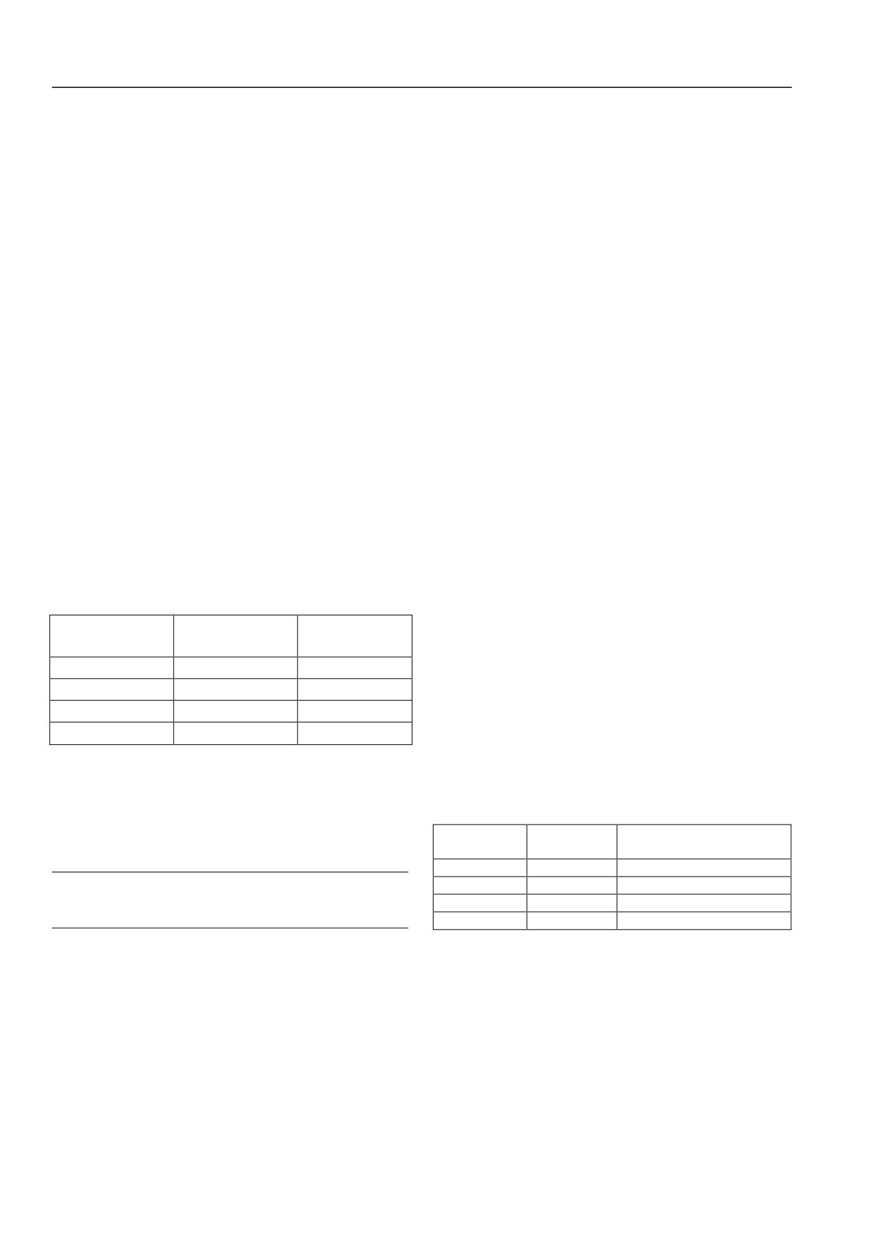
Table 6-9 Torque-Bias Selection
78~79: position option terminals 1~2
Spindle directional position of P09.22~P09.25 can be selected by
Torque-bias option
Torque-bias option
Torque bias value
terminal 2
terminal 1
the combination of the two terminals.
OFF
OFF
No torque bias
Select two control terminals from X1~X8 and respectively define
its function as position option 1 and 2. Take control terminals X6
OFF
ON
Torque bias value1
and X7 as an example, set P10.05=78 and P10.06=79. By the
ON
OFF
Torque bias value 2
combination of terminals X6 and X7, it is valid to select a set
ON
ON
Torque bias value 3
position.
60: AI torque-bias retention
Specific combination is as follows:
When the terminal is valid, AI input at this moment is converted
Table 6-10 Selection of Spindle Position
into corresponding torque bias value. It is requested to set the
corresponding function as torque bias in the analog input function
Position option
Position option
selection in the P11 group; the torque bias value does not vary
Spindle position
terminal 2
terminal 1
with AI input voltage.
OFF
OFF
Spindle position 1
Attention
OFF
ON
Spindle position 2
After given AI is changed, if AI torque bias needs to vary with
ON
OFF
Spindle position 3
it, the terminal should be enabled again.
ON
ON
Spindle position 4
61: pulse input terminal of torque limitation 1
80: Reserved
The function is set only for terminal X8. Torque limit
1 is
81: servo control switching terminal
determined by external input pulse frequency. When external
When current control mode is speed/torque control (P09.00=1),
input pulse frequency reaches maximum input frequency P10.13,
the switching terminal can be enabled to switch it to servo control
the corresponding torque limit 1 is 300%.
mode.
62: pulse input terminal of torque limitation 2
When current control mode is servo control (P09.00=2), the
The function is set only for terminal X8, similar to function 61.
switching terminal can be enabled to switch it to speed/torque
63: pulse input terminal of torque given
control mode.
The function is set only for terminal X8. Given value of torque is
See the description of function codes in the P09 group.
determined by external input pulse frequency. Pulse input of
70
Chapter VI Function Code Details
82: Reserved
正转
Forward
83: position reference point input terminal
When ones place of P09.02 is equal to 1 and position reference
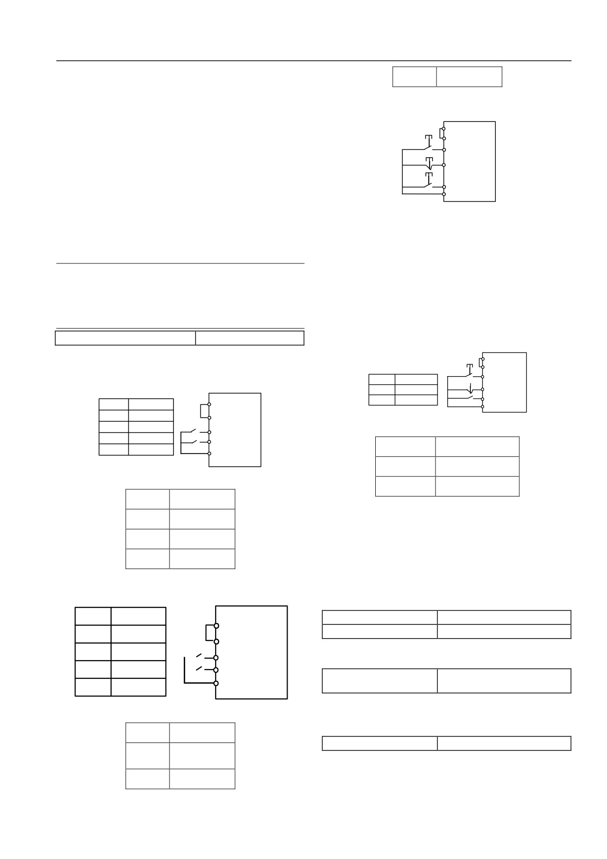
2: three-wire run mode 1
point input terminal is valid, photoelectric switch signal is
P24
inputted through the position reference point.
SB2
PLC HSD2000
84: origin return-to-zero
FWD
SB1
In the spindle orientation control mode, when origin return-to-zero
Xi
terminal is valid, spindle position is 0, or else one of spindle
SB3
REV
positions 1~4 (P09.22~P09.25) should be selected.
COM
85~87: Reserved
Fig. 6-30 Three-Wire Run Mode 1
88: switching terminal of motors 1 and 2
In which,
When the terminal is valid, switching control of the two motors
SB1: stop button
can be realized.
SB2: forward button
Attention
SB3: reverse button
Only the following function numbers are displayed in the
shortcut menu.
Xi stands for multi-function input terminals X1~X8 and here the
0, 7, 8, 9, 10, 11, 12, 13, 14, 17, 18, 19, 20, 26, 27, 35, 37, 45, 46,
corresponding terminal function should be defined as 17# function
47, 48。
“three-wire run control”.
P10.08 FWD/REV run mode setting
0~3【0】
3: three-wire run mode 2
The parameter defines four different modes of controlling running
P24
HSD2000
of servo driver by an external terminal.
SB2
PLC
k
Run direction option
FWD
0: 1 two-wire run mode 1
SB1
0
Reverse
Xi
K
1
Forward
REV
k
k
Run
P24
HSD
2
1
COM
instruction
2000
0
0
Stop
PLC
1
0
Revers
K1
Fig. 6-31 Three-Wire Run Mode 2
e
FWD
0
1
Forward
K2
REV
运行方向选择
Run direction option
1
1
Stop
COM
反转
Reverse
Fig. 6-28 Two-Wire Run Mode 1
正转
Forward
运行指令
Run instruction
停止
Stop
In which,
反转
Reverse
SB1: stop button
正转
Forward
SB2: run button
Xi stands for multi-function input terminals X1~X8 and here the
corresponding terminal function should be defined as 17# function
1: two-wire run mode 2
“three-wire run control”.
k
k
Run instruction
P10.09 Terminal UP rate
0.01~99.99Hz/s【1.00Hz/s】
2
1
HSD
P24
P10.10 Terminal DOWN rate
0.01~99.99Hz/s【1.00Hz/s】
0
0
Stop
2000
PLC
The function code defines the change rate of set frequency
K
1
0
Stop
1
FWD
modified by the terminal UP/DOWN
K
Forwar
2
0
1
REV
P10.11 X8 pulses per
d
1~9999【1024】
Revers
COM
1
1
revolution
e
When the terminal X8 selects 47# function “PG tach input”, actual
Fig. 6-29 Two-Wire Run Mode 2
speed of PG can be measured by setting the value of P10.11 to be
consistent with pulses per revolution of local PG.
运行指令
Run instruction
P10.12 Terminal filtering time
0~500ms【10ms】
停止
Stop
The function code sets filtering time of input terminal detection.
When input terminal state changes, if it remains unchanged after
反转
Reverse
the set filtering time has passed, the change of terminal state is
71
Chapter VI Function Code Details
valid, or else it still keeps previous state, to effectively reduce
Correspondin
misoperations arising from interference.
g value
P10.13 Maximum input pulse
0.1~100.0kHz【10kHz】
frequency
The function code sets maximum input pulse frequency when the
terminal X8 is used for pulse input.
0
P10. 13
P10. 13
2
f
P10.14 Pulse given center point
0~2【0】
option
Fig. 6-34 Center Point Mode 2
对应量
Corresponding value
The function code defines three different midpoint modes when
脉冲频率
Pulse frequency
the terminal X8 is used for pulse input.
0: centerless midpoint, as shown in the figure below:
Correspondi
ng value
P10.15 Pulse given filtering time
0.00~10.00s【0.05s】
The function code defines filtering time of input pulse. The longer
the filtering time is, the lower the change rate of given pulse
frequency is.
P10.16 Valid state setting of input
000~3FFH【000H】
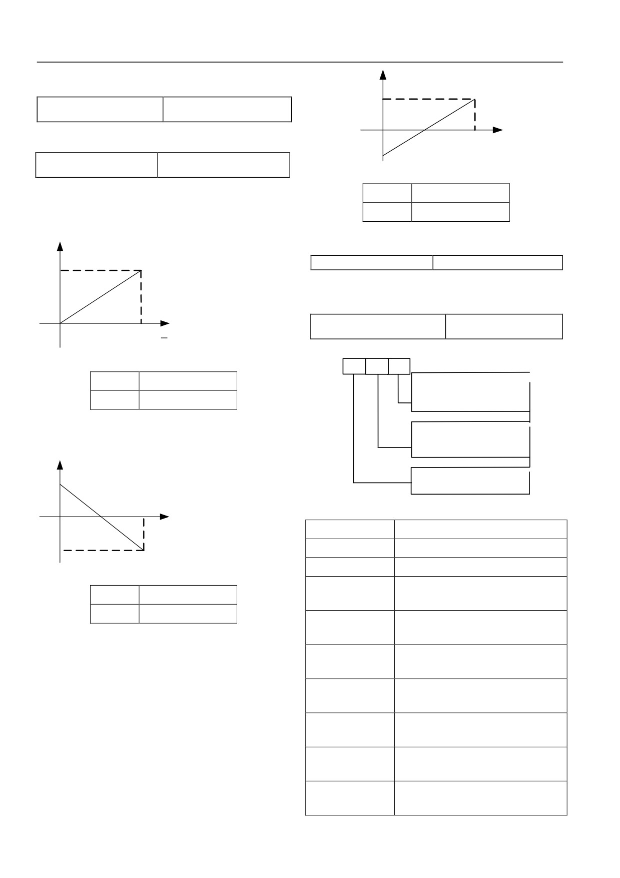
0
P10. 13
terminal
Pulse frequency f
One
Fig. 6-32 Centerless Midpoint Mode
Tens
Hundreds
s
plac
place
plac
e
e
BIT0: Positive and negative logic definition of X1
对应量
Corresponding value
BIT1: Positive and negative logic definition of X2
BIT2: Positive and negative logic definition of X3
脉冲频率
Pulse frequency
BIT3: Positive and negative logic definition of X4
BIT4: Positive and negative logic definition of X5
Values corresponding to pulse input frequencies are all positive.
BIT5: Positive and negative logic definition of X6
BIT6: Positive and negative logic definition of X7
1: center point mode 1
BIT7: Positive and negative logic definition of X8
Corresponding
BIT0: Positive and negative logic definition of FWD
value
BIT1: Positive and negative logic definition of REV
Pulse frequency f
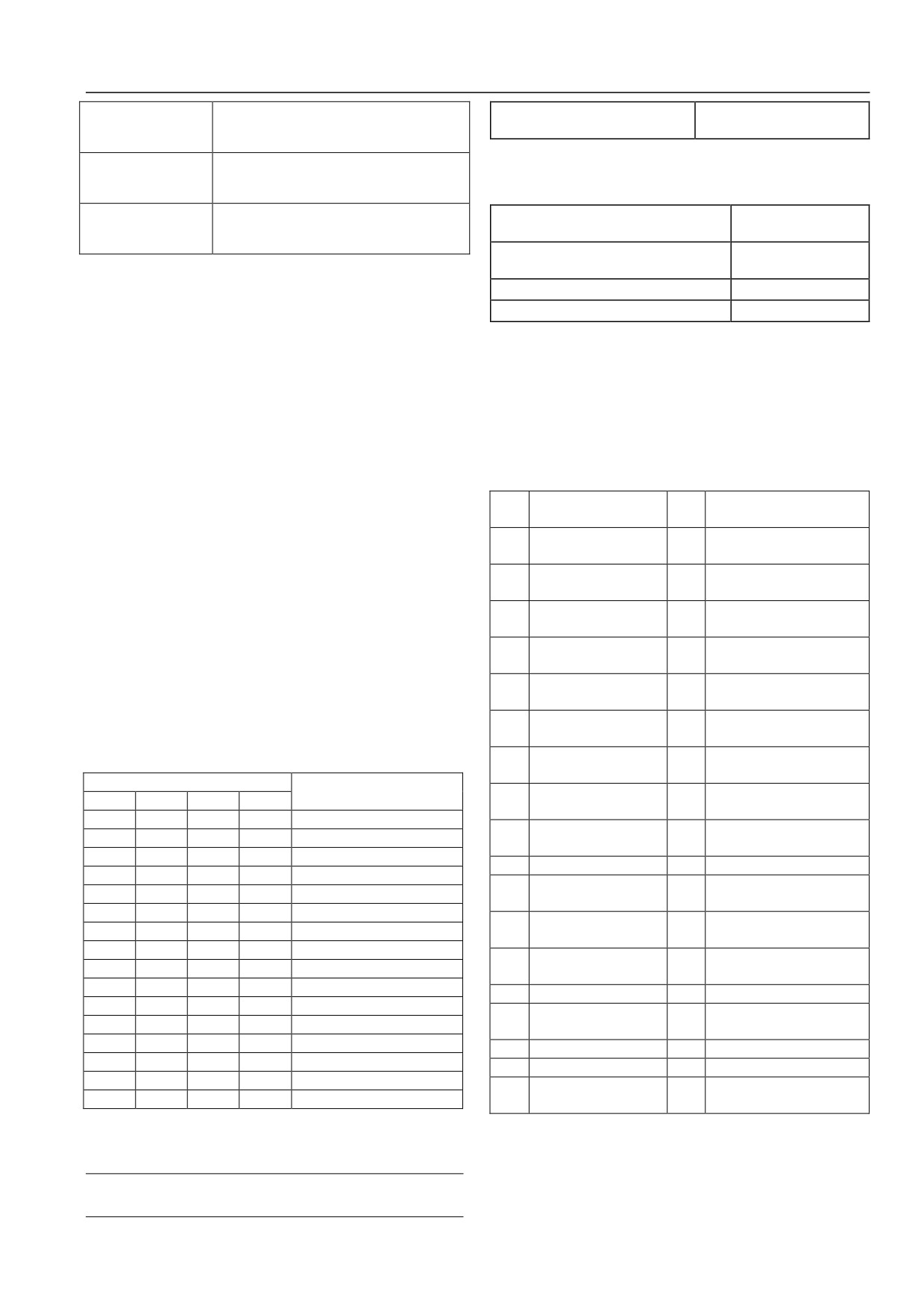
Fig. 6-35 Positive and Negative Logic Setting of Terminals
0
P10. 13
P10. 13
个位
Ones place
2
十位
Tens place
百位
Hundreds place
Fig. 6-33 Center Point Mode 1
X1 的 正 反 逻 辑 定
Positive and negative logic definition
of
对应量
Corresponding value
义
X1
脉冲频率
Pulse frequency
X2 的 正 反 逻 辑 定
Positive and negative logic definition
of
X2
义
Pulse input has a center point and the center point is half of
X3 的 正 反 逻 辑 定
Positive and negative logic definition
of
maximum pulse input frequency P10.13. When input pulse
X3
义
frequency is less than midpoint frequency, corresponding values
are positive.
X4 的 正 反 逻 辑 定
Positive and negative logic definition
of
2: center point mode 2
义
X4
Pulse input has a center point and the center point is half of
X5 的 正 反 逻 辑 定
Positive and negative logic definition
of
maximum pulse input frequency P10.13. When input pulse
义
X5
frequency is greater than midpoint frequency, corresponding
X6 的 正 反 逻 辑 定
Positive and negative logic definition
of
values are positive.
X6
义
X7 的 正 反 逻 辑 定
Positive and negative logic definition
of
义
X7
72
Chapter VI Function Code Details
X8 的 正 反 逻 辑 定
Positive and negative logic definition of
P10.17 State setting of virtual input
000~3FFH【000H】
terminal
义
X8
The function code is used to set valid state of virtual input
FWD 的 正 反 逻 辑
Positive and negative logic definition of
terminals of upper computer. For the detailed setting method, see
FWD
定义
P10.16 description.
REV 的正反逻辑定
Positive and negative logic definition of
P10.18 Output terminal Y1 of open
0~35【0】
REV
collector
义
P10.19 Output terminal Y2 of open
0~35【1】
collector
The function code defines positive and negative logics of input
P10.20 Output function option of relay BR
0~35【15】
terminals.
P10.21 Output function option of relay T
0~35【16】
Positive logic: it is valid when an Xi terminal and its
corresponding common port are connected and invalid when
Output characteristics of Two-way open collector output terminals
disconnected;
Y1 and Y2 and relay output terminals are described in Chapter 4.
Negative logic: it is invalid when an Xi terminal and its
Table 6-12 gives the options of the above four function parameters
corresponding common port are connected and valid when
and it is allowed to repeatedly select the same output terminal
disconnected;
function.
When BIT place is 0, it is positive logic and BIT place is 1, it is
Table 6-12 Function Selection of Output Terminals
negative logic.
For example,
Conte
Cont
Corresponding function
Corresponding function
nt
ent
If X1~X8 are required to be positive logic and FWD and REV
Servo driver running
Frequency arrival signal
are negative logic, setting is as below:
0
1
signal (RUN)
(FAR)
Logic state of X4 ~ X1 is
0000 and the corresponding
Frequency detection signal
2
Speed non-zero signal
3
hexadecimal system is 0, and LED displays 0 in the ones place;
(FDT1)
logic state of X8~X5 is 0000 and the corresponding hexadecimal
Frequency detection
Overload detection signal
4
5
signal (FDT2)
(OL)
system is 0, and LED displays 0 in the tens place; logic state of
Undervoltage lockout
REV and FWD is 11 and the corresponding hexadecimal system is
6
7
External fault shutdown (EXT)
(LU)
3, and LED displays 3 in the hundreds place; here function code
Upper frequency limit
P10.16 should be set as 300 and determination method of set
8
9
Lower frequency limit (FLL)
(FHL)
value is as shown in table 6-11 below:
Servo driver running at
Completion indication of
10
11
Table
6-11 Correspondence Relation between Binary System
zero speed
simple PLC phase run
Completion indication of
Upper and lower limits of
Setting and LED Place Display Value
12
13
PLC cycle
traverse frequency
Binary system setting
Hexadecimal system
Servo driver ready for running
BIT3
BIT2
BIT1
BIT0
(LED place display value)
14
Encoder direction output
15
(RDY)
0
0
0
0
0
On-off signal of upper
0
0
0
1
1
16
Servo driver fault
17
computer
0
0
1
0
2
18
Reserved
19
Torque under limitation
0
0
1
1
3
Magnetic flux detection
0
1
0
0
4
20
21
Reserved
signal
0
1
0
1
5
Over-torque/under-torque
0
1
1
0
6
22
Analog torque bias valid
23
output 1
0
1
1
1
7
Over-torque/under-torque
1
0
0
0
8
24
25
Positioning completed
output 2
1
0
0
1
9
26
Positioning approach
27
Reserved
1
0
1
0
A
Position out-of-tolerance
1
0
1
1
B
28
29
Reserved
alarm
1
1
0
0
C
30
Reserved
31
Reserved
1
1
0
1
D
32
Reserved
33
Reserved
1
1
1
0
E
Forward/reverse running
1
1
1
1
F
34
35
Indication of motors 1 and 2
indication of servo driver
The functions listed in table 6-12 are described as follows:
LED place refers to the thousands place, hundreds place, tens
0: servo driver running signal (RUN)
place and ones place displayed by LED on the operating panel.
When servo driver is in running state, an indication signal will be
Attention
outputted.
Factory settings of all terminals are positive logic.
73
Chapter VI Function Code Details
1: frequency arrival signal (FAR)
Refer to the function description of P10.26.
2: speed non-zero signal
When servo driver is in running state and the speed is greater than
P05.15
“stop speed”, an indication signal will be outputted.
Detection mode of speed non-zero is set by P05.16 “detection
mode of stop speed”.
Attention
Zero-speed detection is valid in all control modes.
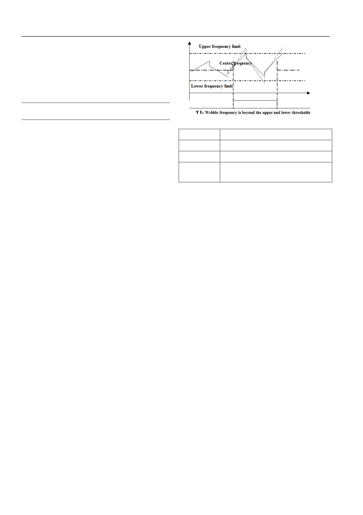
Fig. 6-36 Amplitude Limit of Traverse Frequency
3: frequency detection signal (FDT1)
上限频率
Upper frequency limit
Refer to the function description of P10.28~P10.29.
摆频中心频率
Center frequency
4: frequency detection signal (FDT2)
下限频率
Lower frequency limit
Refer to the function description of P10.30~P10.31.
摆频超出上下
Traverse frequency is beyond the upper and
5: overload detection signal (OL)
lower thresholds
When output current of servo driver exceeds P20.10 overload
限阀值
pre-alarm detection level and time is greater than P20.11 overload
pre-alarm detection time, an indication signal will be outputted. It
14: output of encoder frequency division direction
is often used for overload pre-alarm.
It is indicate the direction signal of frequency division output of
6: undervoltage lockout (LU)
current encoder.
When DC bus voltage is lower than undervoltage limit level, an
indication signal will be outputted and LED will display “P.oFF”.
15: servo driver ready for running (RDY)
7: External fault shutdown (EXT)
When the signal output is valid, it shows servo driver is fault-free,
When servo driver gives an external fault trip alarm (E015), an
bus voltage is normal, run disable terminal of servo driver is
indication signal will be outputted.
invalid, and servo driver can receive a start command.
8: Upper frequency limit (FHL)
16: servo driver fault
When set frequency is greater than or equal to the upper frequency
When servo driver breaks down, an indication signal will be
limit and running frequency reaches the upper frequency limit, an
outputted.
indication signal will be outputted.
17: on-off signal of upper computer
9: Lower frequency limit (FLL)
Output signals of Y1 and Y2 or BR and T are directly controlled
When set frequency is less than or equal to the lower frequency
by serial ports. Output is also affected by P10.17.
limit and running frequency reaches the lower frequency limit, an
18: Reserved
indication signal will be outputted.
10: Servo driver running at zero speed
19: torque under limitation
When servo driver is in zero-speed running state, an indication
When a torque instruction is restricted by torque limit 1 or 2, an
signal will be outputted. Specifically speaking, in V/F mode,
indication signal will be outputted.
when output frequency is 0, an indication signal will be outputted;
20: magnetic flux detection signal
in non-V/F mode, when feedback frequency is less than P10.37
When magnetic flux detection value exceeds P10.37, an indication
corresponding frequency, an indication signal will be outputted.
signal will be outputted.
11: completion indication of simple PLC phase run
21: Reserved
After simple PLC run in current phase is completed, an indication
signal (single pulse signal, width: 500ms) will be outputted.
22: analog torque bias valid
12: completion indication of PLC cycle
When input terminal function is set as 60 “torque-bias retention”
After simple PLC completes a run cycle, an indication signal
and it is valid, an indication signal will be outputted.
(single pulse signal, width: 500ms) will be outputted.
23: over-torque/under-torque output 1
13: upper and lower limits of traverse frequency
According to setting of P08.17 ~ P08.19, the corresponding
After the traverse frequency function is selected, if the fluctuation
indication signal will be outputted.
range of traverse frequency calculated based on center frequency
24: over-torque/under-torque output2
exceeds the upper frequency limit P02.06 or is below the lower
frequency limit P02.07, an indication signal will be outputted, as
According to setting of P08.20 ~ P08.22, the corresponding
shown in Fig.6-36.
indication signal will be outputted.
25: positioning completed
74
Chapter VI Function Code Details
In running state, when position control is selected and position
negative logic
(invalid when connected and valid when
deviation is less than or equal to P09.12, the corresponding
disconnected).
indication signal will be outputted.
P10.23 Output delay of relay BR
0.1~10.0s【0.1s】
26: positioning approach
P10.24 Output delay of relay T
0.1~10.0s【0.1s】
In running state, when position control is selected and position
The function code defines the time delay from change of relay
deviation is less than or equal to P09.13, the corresponding
state to variation of relay output.
indication signal will be outputted.
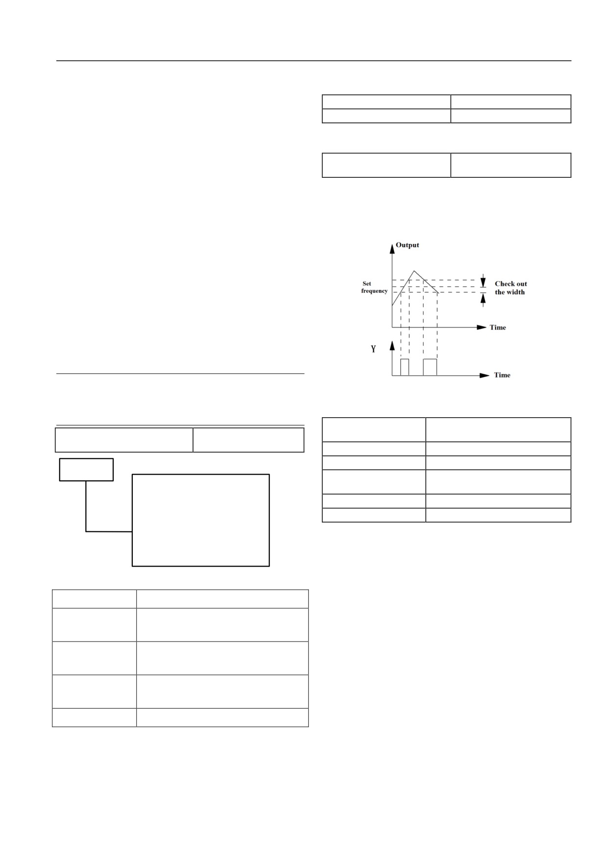
P10.25 Frequency arrival (FAR)
0.00~1000.0Hz【2.50Hz】
27: Reserved
detection width
The parameter is the supplementary definition of 1# function in
28: position out-of-tolerance alarm
table 6-12. As shown in Fig.6-38, when output frequency of servo
In running state, when position control is selected and position
driver is within positive and negative detection width of set
deviation is greater than or equal to P09.14 “detection range of
frequency, a pulse signal will be outputted.
position out-of-tolerance” and P09.15 position out-of-tolerance
alarm option 0 is valid, the corresponding indication signal will be
outputted.
29~33: Reserved
34:forward/reverse running indication of servo driver
The corresponding indication signal will be outputted according to
actual running direction of current servo driver.
35: indication of motors 1 and 2
The corresponding indication signal will be outputted according to
current selected motor.
Attention
Fig. 6-38 FAR Signal Output Diagram
Only the following function numbers are displayed in the
shortcut menu.
0, 1, 4, 5, 6, 7, 8, 9, 15, 16.
P10.26 FDT1 detection
0~1【0】
P10.22 Valid state setting of output
mode
0~FH【0H】
terminal
P10.27 FDT1 level
0.00~1000.0Hz【50.00Hz】
P10.28 FDT1 lag
0.00~1000.0Hz【1.00Hz】
Onces place
P10.29 FDT2 detection
0~1【1】
BIT 0:Positive and negative logic
mode
definition of Y1
P10.30 FDT2 level
0.00~1000.0Hz【25.00Hz】
BIT1:
Positive and negative logic
P10.31 FDT2 lag
0.00~1000.0Hz【1.00Hz】
definition of Y2
BIT2: Positive and negative
P10.27~P10.29 are the supplementary definition of 3# function
logic definition of BR
in table 6-12; P10.30~P10.32 are the supplementary definition of
BIT3:Positive and negative
4# function in table 6-12; the usage of both is the same. Take
logic definition of T
P10.27~P10.29 as an example to give a description below:
Fig. 6-37 Valid State Setting of Output Terminal
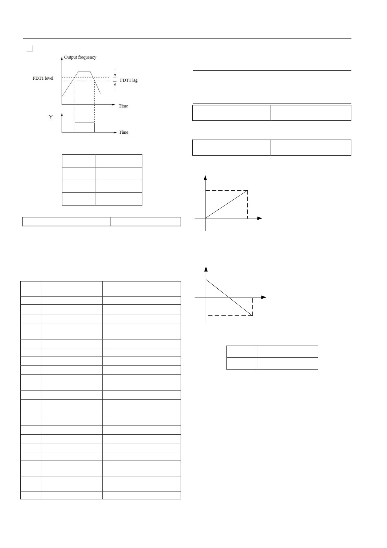
Firstly set P10.27 “FDT1 detection mode” to determine the source
个位
Ones place
of set frequency.
Y1 的正反逻辑定
Positive and negative logic definition of Y1
0
: speed setting value
(frequency instruction after
义
acceleration/deceleration)
Y2 的正反逻辑定
Positive and negative logic definition of Y2
1: speed detection value
义
When output frequency exceeds the set frequency (FDT1 level),
an indication signal will be outputted until output frequency drops
BR 的正反逻辑定
Positive and negative logic definition of
down to a certain frequency lower than FDT1 level (FDT1 level-
BR
义
FDT1 lag). As shown in Fig.6-39.
T 的正反逻辑定义
Positive and negative logic definition of T
The function code defines positive and negative logic of output
terminal.
When BIT place is 0, it is positive logic (valid when connected
and invalid when disconnected); when BIT place
1 is, it is
75
Chapter VI Function Code Details
For extended function 1 of upper computer, DO output is directly
controlled by serial port. 65535 corresponds to maximum output
frequency of DO, refer to HSD2000 communication protocol.
Attention
Only the following function numbers are displayed in the
shortcut menu.
0, 1, 2, 3, 4, 5, 6, 7, 8.
P10.33 Maximum output pulse
0.1~100kHz【10.0】
frequency
The function code defines maximum output frequency of DO
pulse.
P10.34 Pulse output center point
Fig. 6-39 Frequency Detection Diagram
0~2【0】
option
输出频率
Output frequency
The function code defines three different center point modes of
DO terminal pulse output.
FDT1 电平
FDT1 level
FDT1 滞后
FDT1 lag
Corresponding
value
时间
Time
P10.32 DO terminal output
0~19【0】
0
P10.33
Pulse
Output of DO pulse frequency:
0~ maximum output pulse
frequency f
Fig. 6-40 Centerless Midpoint Mode
frequency (defined by P10.33).
The linear correspondence relation between DO output and
Values corresponding to pulse output frequencies are all positive.
indication range is as shown in table 6-13.
1: center point mode 1, as shown in the figure below:
Table 6-13 Indication of Output Terminal
Correspondin
g value
Conte
Corresponding function
Indication range
Pulse
nt
frequency f
0
Non-function
No
0
P10. 33
P10. 33
2
1
Output frequency
0~maximum output frequency
2
Set frequency
0~maximum output frequency
0~2×rated current of servo
3
Output current Iei
Fig. 6-41 Center Point Mode 1
driver
4
Output current Iem
0~3×rated current of motor
5
Output torque
0~3×rated motor torque
对应量
Corresponding value
6
Output torque current
0~3×torque current
脉冲频率
Pulse frequency
7
Motor speed
0~ maximum speed
1.5× rated voltage of servo
0~
8
Output voltage
Pulse output has a center point and the center point is half of
driver
maximum pulse output frequency P10.13. When output pulse
9
Adjusted AI1 voltage
-10V~10V/4~20mA
frequency is less than midpoint frequency, corresponding values
10
Adjusted AI2 voltage
-10V~10V/4~20mA
are positive.
11
Adjusted AI3 voltage
-10V~10V
2: center point mode 2
12
Output power
0~3×rated power
13
Torque limit 1
0~3×rated motor torque
Pulse output has a center point and the center point is half of
14
Torque limit 2
0~3×rated motor torque
maximum pulse output frequency P10.13. When output pulse
15
Torque bias
0~3×rated motor torque
frequency is greater than midpoint frequency, corresponding
values are positive.
16
Torque given
0~3×rated motor torque
Extended function 1 of
17
0~65535
upper computer
Frequency division
18
output of encoder
19
Reserved
76
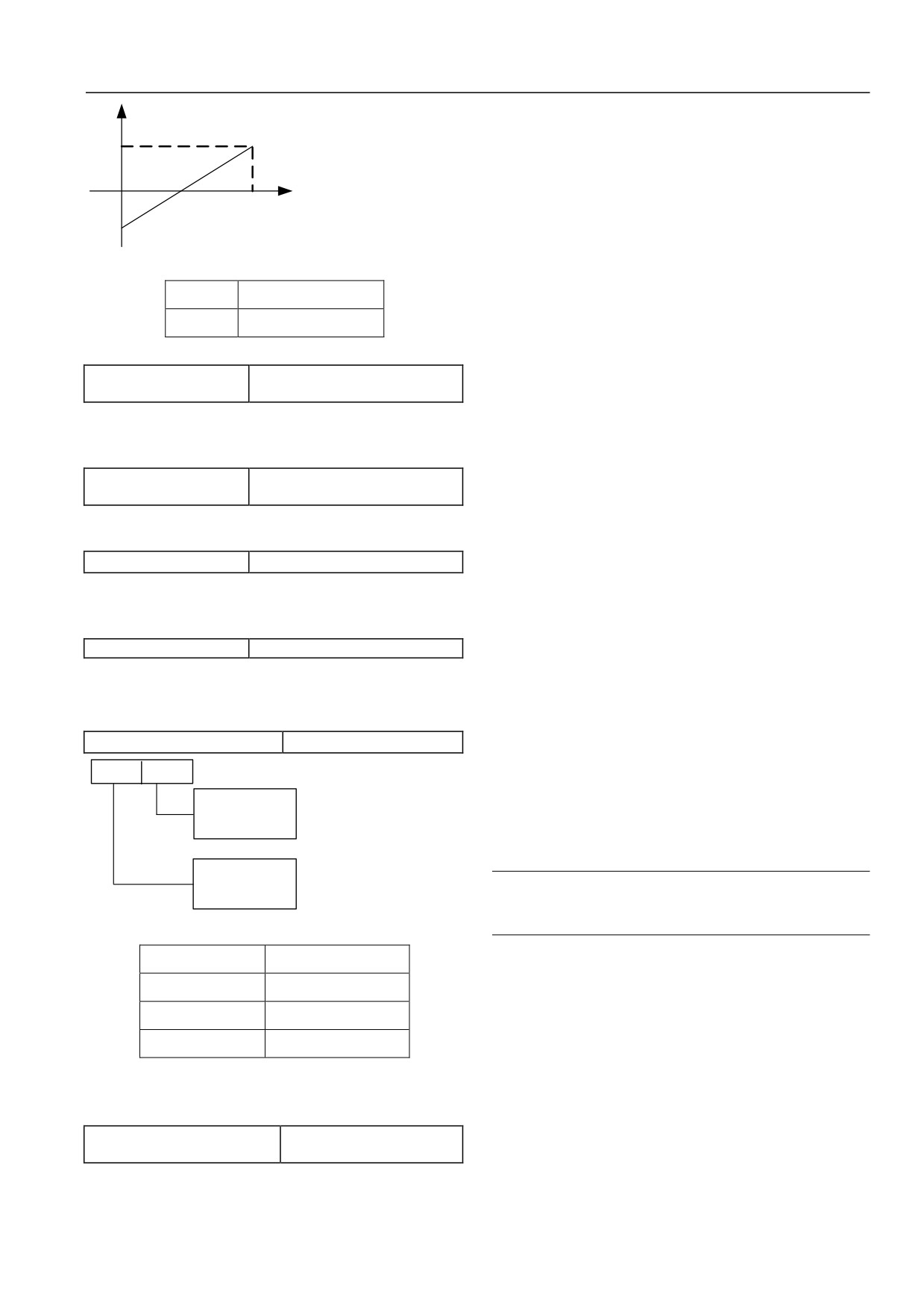
Chapter VI Function Code Details
When the function is selected, it is used in conjunction with
Correspondin
g value
P02.03 function code. When serving as voltage input, the polarity
of analog input affects running direction of servo driver: when
analog input is positive, servo driver rotates forward; on the
contrary, servo driver rotates reversely. Maximum value
0
P10. 33
P10. 33
(10V/20mA) of analog input corresponds to maximum output
2
Pulse frequency f
frequency of servo driver.
2: auxiliary set frequency given
Fig. 6-42 Center Point Mode 2
When the function is selected, it is used in conjunction with
对应量
Corresponding value
P02.08 function code. When serving as voltage input, the polarity
脉冲频率
Pulse frequency
of analog input affects the polarity of auxiliary frequency: when
analog input is positive, auxiliary frequency is positive; on the
contrary, auxiliary frequency is negative. Maximum value
P10.35 Filtering time of pulse
0.00~10.00s【0.05s】
(10V/20mA) of analog input corresponds to maximum output
output
frequency of servo driver.
The function code defines the filtering time of output pulse. The
3: torque bias
longer the filtering time is, the lower the change rate of output
When the function is selected, AI torque bias retention function
pulse frequency is.
should be selected for switch input terminal. When serving as
P10.36 Magnetic flux
10.0%~100.0%【100.0%】
voltage input,
-10~10V corresponds to -100%~100%
detection value
rated motor torque; when serving as current input,
4~20mA
It is used in conjunction with
20# function of switch output
terminal.
corresponds to 0~100%rated motor torque.
P10.37 Zero-speed threshold
0.0%~100.0%【1.0%】
When analog input serves as torque bias, an application example
is given as below:
The function code is relative to maximum output frequency
P02.05 and it is used in conjunction with 10# function of switch
AI1 analog input 4~20mA corresponds to 0~100% rated motor
output terminal.
torque of indication analog given torque bias
P10.38 Reserved
Setting is as below:
Reserved function
1)P11.01=3, input torque bias;
2)P11.00=01, AI1 input type is 4~20mA;
6.1.12 Analog I/O terminal parameters (P11 group)
3)P11.03=1.0, input gain is 1;
P11.00 Analog input type option
00~11【00】
4)P11.02=0, zero-bias correction is 0.
Tens
Ones place
5)Select the function 60 of switch input terminal Xi and make
place
the terminal Xi have a switch-off~ switch-on jump (only
AI1input type option
0: -10:
10V
this way can make analog input torque bias valid, or else
1: 4:
20mA
analog input given torque bias always remains to be
previous analog given value).
AI2input type option
0: -10:
10V
Attention
1: 4:
20mA
AI torque bias is just a part of torque bias and final torque
bias also includes setting of P08.12~P08.15.
Fig. 6-43 Analog Input Type Option
十位
Tens place
4: speed limit 1
个位
Ones place
When the function is selected, it is used in conjunction with
AI1 输入类型选择
AI1 input type option
P07.09 function code setting. When serving as voltage input, 0~
±10V corresponds to maximum output frequency of 0~100%
AI2 输入类型选择
AI2 input type option
servo driver; when serving as current input, 20mA corresponds to
maximum output frequency of 0~100% servo driver
The function code is used to select analog input type and range of
5: speed limit 2
AI1 and AI2.
When the function is selected, it is used in conjunction with
P11.01 AI1 terminal input function
0~13【00】
P07.09 function code setting. The meaning of analog input is the
option
same as speed limit 1.
0: non-function
6: torque limit 1
1: main set frequency given
77
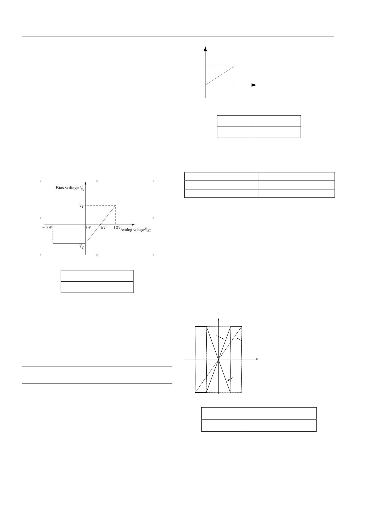
Chapter VI Function Code Details
When the function is selected, it is used in conjunction with
Input
P08.08 function code setting. The meaning of analog input is the
voltage
VO
same as torque bias.
Vma
7: torque limit 2
x
When the function is selected, it is used in conjunction with
0
P08.09 function code setting. The meaning of analog input is the
AImin
AImax
Analog
same as torque bias.
input
8: torque instruction (given)
Fig.6-45 Output Voltage Curve
When the function is selected, it is used in conjunction with
P08.02 function code setting. The meaning of analog input is the
输入电压 VO
Input voltage VO
same as torque bias.
模拟输入
Analog input
9~11: Reserved
In the above figure, horizontal coordinate represents analog input
12: V/F output voltage bias
signal after adjusted and vertical coordinate represents output
When analog input is voltage signal and analog input terminal
voltage of servo driver. When input analog voltage is less than
function is output voltage bias, the corresponding output voltage
zero, output voltage is also zero.
bias is as shown in Fig. 6-44.
P11.02 AI1 zero-bias correction
-100.0~100.0%【0.0%】
P11.03 AI1 input gain
-10.00~10.00【1.00】
P11.04 AI1 input filter
0.01~10.00s【0.05】
Maximum output of AI zero bias is 100% (10V or 20mA) and
both upper and lower translation values are set in percentage.
Take voltage input for example, the relation between zero bias and
gain before and after adjusted is as below:
AI input value = input gain × given analog value + zero-bias
correction ×10V
P11.04 defines channel filtering time constant and input signal is
Fig.6-44 Output Voltage Bias
filtered; the longer the filtering time is, the higher the interference
resistance is, but the response becomes slow; the shorter the
偏置电压
Bias voltage
filtering time is, the quicker the response is, but the interference
模拟电压
Analog voltage
resistance becomes weak.
The curve of relation between analog input and gain and the curve
of relation between analog input and zero-bias correction are
Supposing output voltage that set frequency corresponds to in V/F
respectively as shown in Fig.6-46 and Fig.6-47.
curve is V/F, the relation between input analog signal and bias
voltage is as below:
Built-in value of AI input (V)
10
-10V~0V/4mA analog input VAI corresponds to bias voltage
P11.03=2.0
-V/F;
P11.03=1.0
10V/20mA analog input VAI corresponds to bias voltage V/F
:
10
:
5
5
10
Output voltage of servo driver: VO=V/F+Vb
0
Given value of
external
analog(V)
Attention
P11.03=-2.0
Output voltage bias function is valid only in V/F mode.
: 10
13: output voltage
Fig.6-46 Curve of Relation between Analog Input and Gain
When the function is valid in V/F mode, output voltage VO of
AI 输入机内值
Built-in value of AI input
servo driver and its output frequency are completely of mutual
independence. Output voltage of servo driver is not restricted by
外部模拟给定值
Given value of external analog
V/F characteristic curve in the P06 group and it depends on analog
input signal, as shown in Fig.6-45.
78
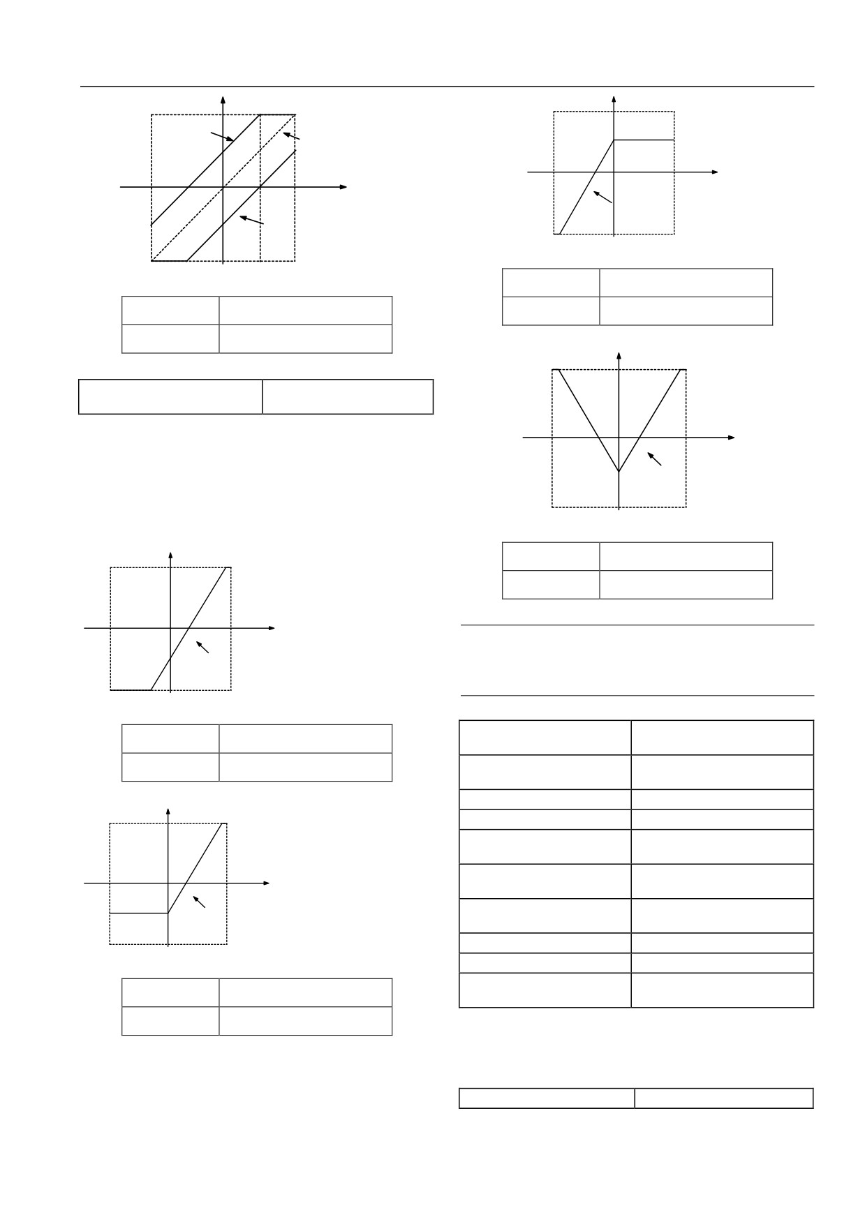
Chapter VI Function Code Details
Built-in value of AI inp:t V:
Built-in value of AI input (V)
10
P11.02=50.0
10
%
P11.02=0
:
10
10
0
Given value of
:
10
:
5
5
10
external analo: V:
0
Given value of
external analog(V)
P11 . 02=50 . 0:
P11.02=-
50.0%
:
10
:
10
Fig.6-50 Above Zero Bias Is Equal To Zero Bias Correction Mode
Fig.6-47 Curve of Relation between Analog Input and Zero Bias
AI 输入机内值
Built-in value of AI input
AI 输入机内值
Built-in value of AI input
外部模拟给定值
Given value of external analog
外部模拟给定值
Given value of external analog
Built-in value of AI inp
: V:
10
P11.05 AI1 zero-bias correction
0~3【0】
mode
0: zero bias-centered
:
10
10
0
1: below zero bias is equal to zero bias
Given value of
: V:
external analog
2: above zero bias is equal to zero bias
P11 . 02=:
50 .0:
3: zero bias-centered absolute value
:
10
The meanings of the four values are respectively shown as Fig.
Fig.6-51 Zero Bias-Centered Absolute Value Correction Mode
6-48, Fig. 6-49, Fig.6-50 and Fig.6-51.
AI 输入机内值
Built-in value of AI input
Built-in value of AI input (V)
10
外部模拟给定值
Given value of external analog
:
10
0
1
0
Given value of
Attention
external
analog(V)
P11 . 02=:
50 .0:
Input gain and zero-bias correction function codes have a
real-time influence on analog input in the modification
:
10
process.
Fig.6-48 Zero Bias-Centered Correction Mode
P11.06 AI2 terminal input
AI 输入机内值
Built-in value of AI input
0~11【00】
function option
外部模拟给定值
Given value of external analog
P11.07 AI2 zero-bias
-100.0~100.0%【0.0%】
correction
P11.08 AI2 input gain
-10.00~10.00【1.00】
Built-in value of AI input (V)
P11.09 AI2 input filter
0.01~10.00s【0.05】
10
P11.10 AI2 zero-bias
0~3【0】
correction mode
P11.11 AI3 terminal input
:
10
10
0~11【00】
0
Given value of
function option
external
analog(V)
P11.12 AI3 zero-bias
P11 . 02=:
50 .0:
-100.0~100.0%【0.0%】
correction
:
10
P11.13 AI3 input gain
-10.00~10.00【1.00】
Fig.6-49 Below Zero Bias Is Equal To Zero Bias Correction Mode
P11.14 AI3 input filter
0.01~10.00s【0.05】
P11.15 AI3 zero-bias
AI 输入机内值
Built-in value of AI input
0~3【0】
correction mode
外部模拟给定值
Given value of external analog
Function setting of analog input of AI2 terminal and its meaning
are identical with AI1. Function setting and meaning of AI3
terminal as differential voltage input are identical with AI1 as
voltage input.
P11.16 Analog output type option
00~33【00】
79