SERVO DRIVE SV-E3 SERIES. INSTRUCTION MANUAL (v1.5) - page 8
651.0
Home position return Home position data
Command unit(Note 1)
Set a position at the time of home position return complete.
When home position return is completed, change the setting value to ABS position feedback of home position return.
[Setting range] -1, 000, 000, 000~1, 000, 000, 000
[Initial value]
0 [command unit]
No.
Name
Unit
655.0
Home position return Press detection time
ms
Set the time from pressing the stopper to detecting the home position return.
This parameter is valid when the base signal 1 for home position (No.645. 0) is set to “Stopper”.
[Setting range] 5~1, 000
[Initial value] 100[ms]
No.
Name
Unit
656.0
Home position return Torque limit value
0.1%
Set Torque limit value at the time of home position return
This value is measured in terms of proportion to rated torque.
This value is the torque limit value of pressing the stopper when selecting ‘Stopper” in the base signal 1 for home position.
When selecting “Enable” in Home position return Torque limit option(No. 647. 0), this parameter is the safety measure against
collision in home position return .
[Setting range] 10~3, 000
[Initial value] 500[ 0. 1%]
No.
Name
Unit
657.0
Home position return Phase Z invalidation distance
Command unit(Note 1)
Set a distance from the positon where Base signal 1 for home position is detected to the position where Phase Z detection
starts.
[Setting range] 0~1, 000, 000, 000
[Initial value] 0[ command unit]
No.
Name
Unit
659.0
Home position return Timeout Time
10ms
Set Home position return Timeout Time.
This parameter is valid when Home positon return Timeout option(No. 646. 2) is set to :Enable”.
[Setting range] 0~60, 000
[Initial value] 60, 000[ 10ms]
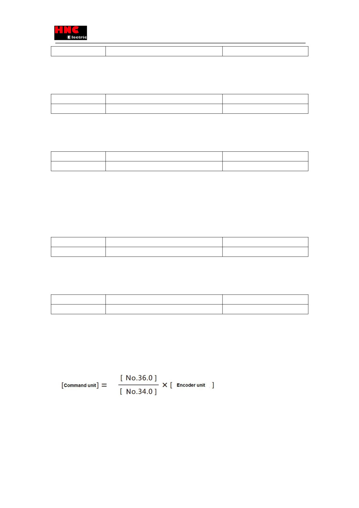
Note 1) The command unit can be got by 「command division and multiplication(numerator) (No. 34. 0)
」, 「command
division and multiplication(denominator) (No. 36. 0)
」 and encoder unit.
The command unit can be got by the encoder unit 131, 072ppr.
For example, when the parameter No. 34. 0 is set to 32, 768, No. 36. 0 is set to 2, 500, the command unit will be 10, 000ppr.
When the ratio of command division and multiplication is 1 times or less, the speed of home position return cannot reach the
speed set in home position return(No. 648. 0) and home position return creep speed (No. 649. 0).
8.9.5 User I/O description
■Input
On when connected to COM- at closed-circuit; OFF when connected to COM- at open-circuit.
140
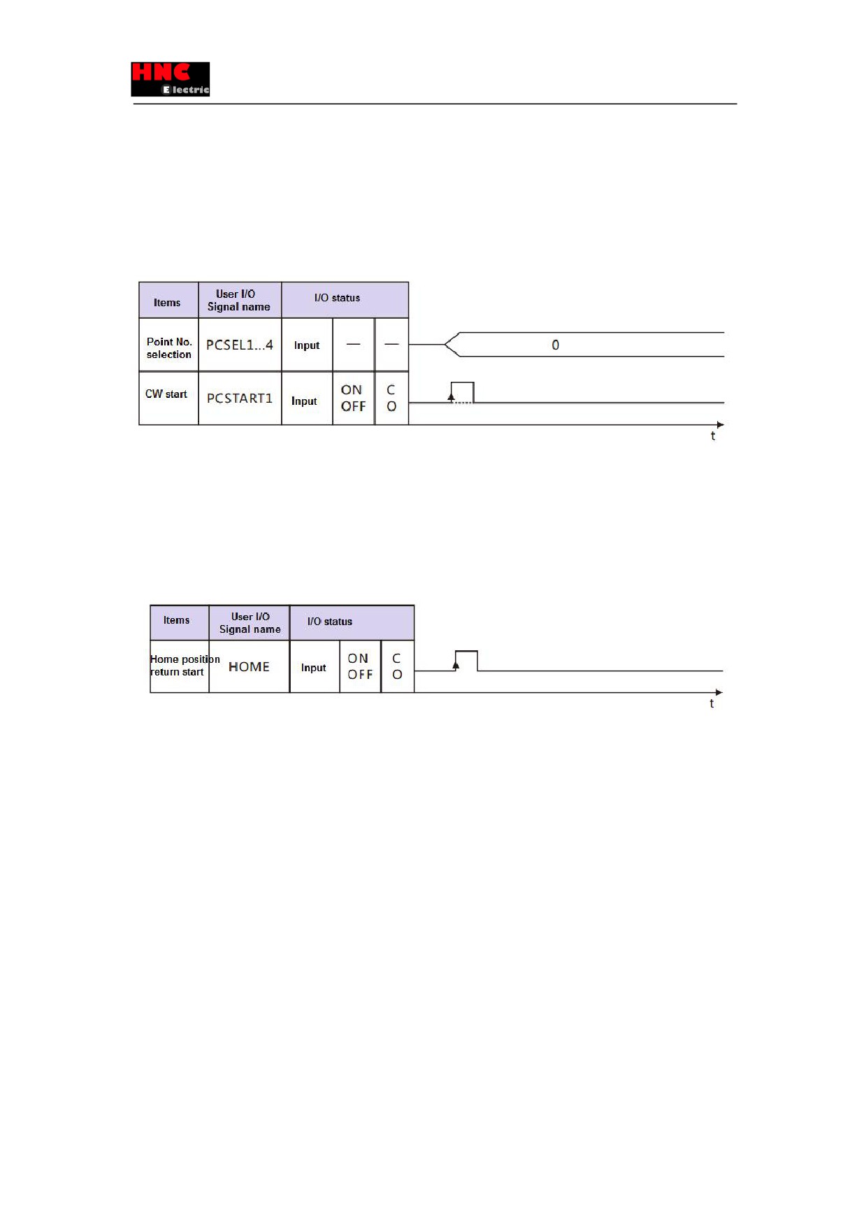
1)PCSTART1 CW start(6 pins)
・Use PCSTART1(6 pins) to start home position return
・Specify “0” to the Point No. in PCSEL1. . . 4 in user I/O, the PCSTART1 changes from open-circuit to closed-circuit to start
the home position return.
2) PCSEL1. . . 4 point No. selection(7~10 pins)
・Set 「Point No.0 function selection」 ( No. 646. 3) to “0: home position return”.
・When perform the home position return by PCSTART1, specify “0” to the Point No. in PCSEL1. . . 4 in user I/O.
Note: C:contact closed-circuit, O: contact open-circuit
Figure 8.9.10 The start of home position return(PCSTART1)
3) Home position return start (Valid when positioner I/O is set to Item 1).
・This parameter is valid when positioner I/O is set to Item 1.
(For the setting of Item 1, refer to「Appendix 3 SV-E3 special I/O setting」)
・The home position return starts from HOME open to close
Note: C:contact closed-circuit, O: contact open-circuit
Figure 8.9.11 The start of home position return(HOME)
4) ORG home position sensor (11 pins)
・Enter the home position sensor signal when have the home position return by home position sensor.
・Have the setting as below:
「Base signal 1 selection for Home position」(No. 645. 0): 2 = Home position DOG frond end
「Home position sensor input polarity」(No. 646. 1): (Either polarity is Ok)
The initial setting of home position sensor input polarity is the home position sensor signal when connected with COM- from
ON to OFF.
■Output
On when connected to COM- at closed-circuit; OFF when connected to COM- at open-circuit.
1) HEND home position return completion (16 pins) (Note 1)
・Change to be ON at home position return completion. When “Absolute system” is selected for “Selection of an encoder
system” (No. 257. 0), there is no need to have the home position return when power ON the drive next time after the home
position return has been completed.
・HEND will be OFF in the following situation:
a) In the process of home position return
141
b) Interrupted before HEND becomes ON in the home position return
The home position return interrupts in the following situations;
○Make the servo OFF in the home position return with the operation
○Perform the deviation counter clearing in the home position return with the operation
○Input the drive restriction and perform the deviation counter clearing in the home position return with the operation
○Alarms occur and servo OFF in the home position return with the operation
c) “Incremental system” is selected to “Selection of an encoder system” after the power is supplied to the drive
d) “Absolute system” is selected for “Selection of an encoder system”, but the multi-rotation data of the encoder disappear.
・The minimum OFF time of the signal is 3ms.
2) MEND completion (15 pins)(Note 1)
・When perform the home position return at servo ON, confirm if you can start the home position return or not. Please make
sure this signal is ON before home position return.
・OFF at servo OFF.
・The minimum OFF time of the signal is 3ms.
3) MEND/T-LIMIT completion / torque limit (Valid when positioner I/O is set to Item 1).
・This parameter is valid when positioner I/O is set to Item 1.
(For the setting of Item 1, refer to「Appendix 3 SV-E3 special I/O setting」)
・Be ON either MEND or T-LIMIT is ON.
・This signal, used in the device of torque limit, including stopper, is T-LIMIT. And the other operations is used as MEND signal.
As T-LIMIT, the torque limit TLSEL1 is ON and as MEND, TLSEL1 is OFF.
Set the following parameters first when using this signal.
“Torque command limit override selection”(No. 144. 0): “1: Enable”
“Selection of Torque limit state output mode(No. 144. 1)”: “2 : Torque command limit Override 2”
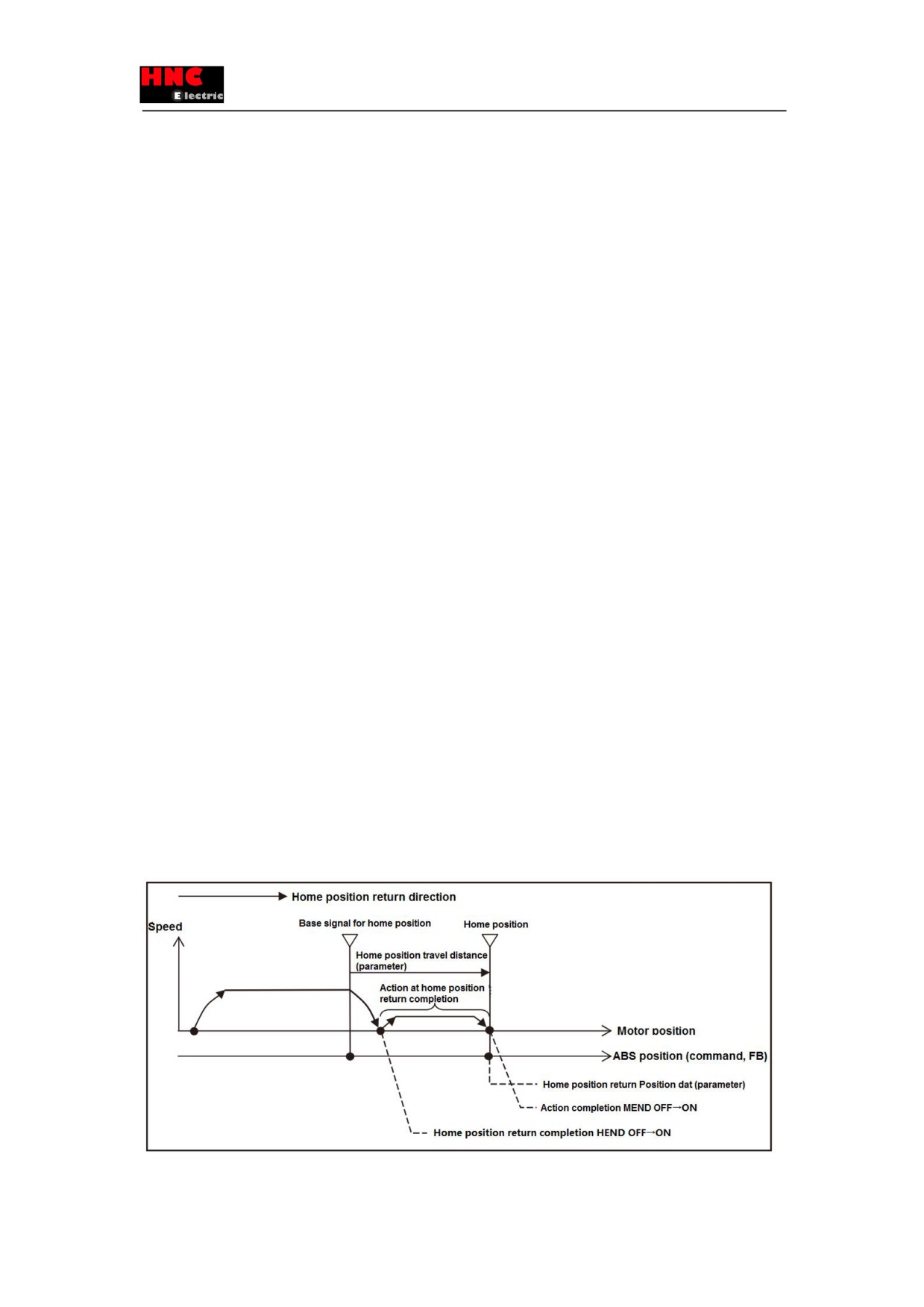
Note 1) Action at home position return completion(No. 647. 1): HEND and MEND
1) When set the Action at home position return completion(No. 647. 1) to “1 = Move”
After the base signal for home position is detected, it will decelerate to stop and HEND is ON at home position return
completion.
Then shift to home position according to the action of home position return completion, the MEND becomes ON after the
operation has been completed. The ABS position command becomes the home position return position data after the
operation has been completed.
Figure8.9.12 Action at home position return completion(when the setting is valid)
142
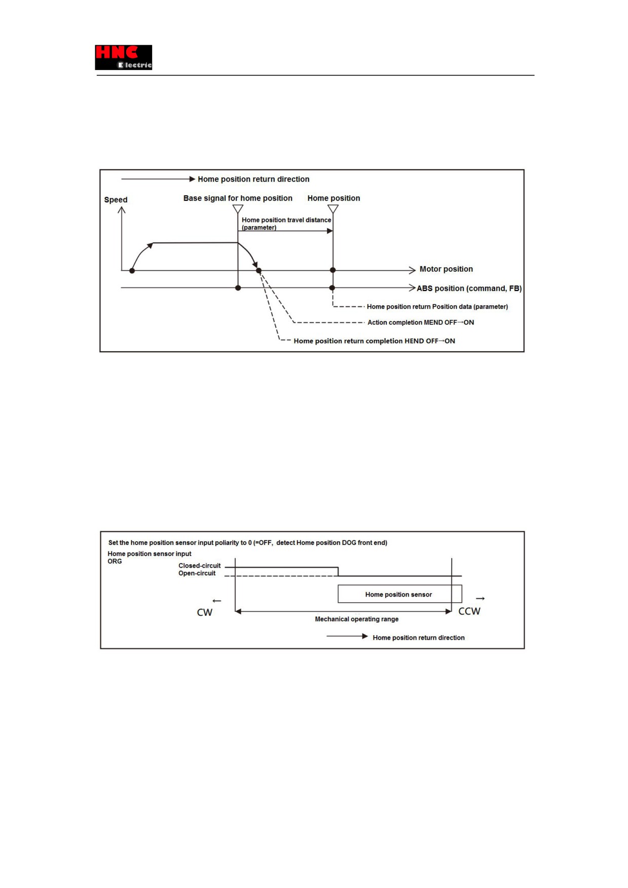
2) When set the Action at home position return completion(No. 647. 1) to “0= No move”
After the base signal for home position is detected, it will decelerate to stop and HEND is ON at home position return
completion.
Then do not shift to the home position return. The action will be completed at the position of deceleration stop and output
MEND to be ON.
Figure8.9.13 Action at home position return completion(when the setting is invalid)
Note2) But, in the following situation, the torque limit value of home position return is applicable for「Home position return
Torque limit value(No.656.0)」.
1) Set「Base signal 1 selection for Home position (No.645.0)」to “1(stopper)”.
2) Set「Home position return Torque limit option (No.647.0)」to “1(Enable)”.
8.9.6 Precautions
1) Install a home position sensor to the machinery when use the Home position DOG front end as the base signal for home
position. Besides, set the “home position return direction”(No. 646. 0) from home position DOG sensor front end to home
position DOG front end. There is the danger of collision for the machinery if the home position direction is far away from the
home position sensor.
2) Please save the parameters after changing the command division and multiplication. Perform the home position return
operation again after power ON next time.
3) When home position return with Encoder phase Z, do not design it to the start position of phase Z detection or near the
motor phase Z. Phase Z detection position sometimes changes. The phase Z position can be confirmed at the position where
the status value of “Encoder 1 rotation angle data” is 0.
4) The home position return will be interrupted and become uncompleted in the following situations at the home position return
with operation.
■Servo OFF
■Deviation counter clearing
143
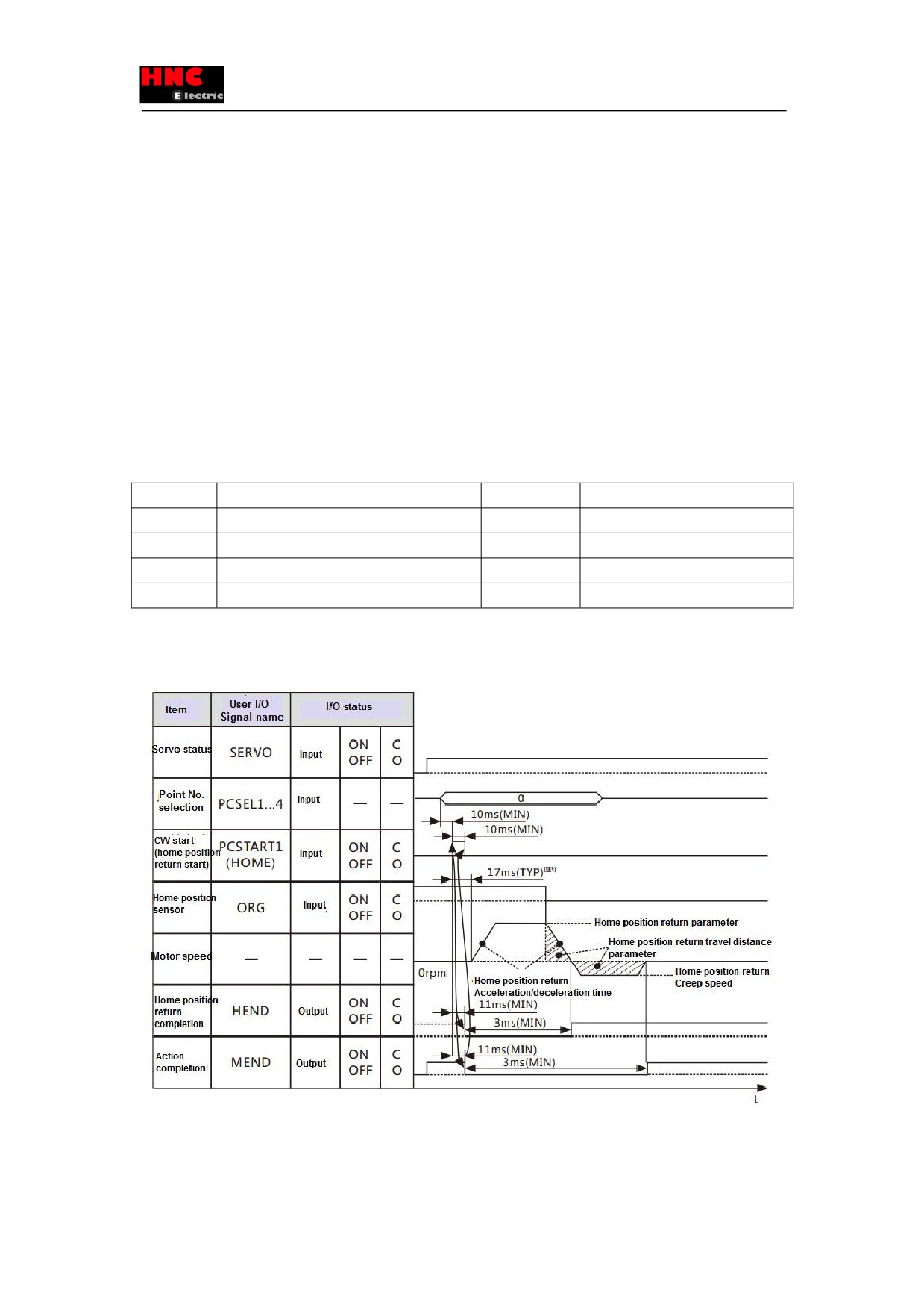
When performing the deviation counter clearing, it will emergency stop.
■Input the drive restriction, then perform the deviation counter clearing.
5) Set the 「Selection of Auto interpolation for command division and multiplication」(No. 32. 2) to “1: Enable”. The initial value
is “1: Enable”. The speed can change rapidly if set it to “0:Disable”.
8.9.7 Precautions
The operation of home position return can be done by user I/O input.
1) By the method of user I/O input
①Set the parameters in table 8.9.1
②Start the home position return in the following method
・After specify Point No. 0 to the PCSEL1. . . 4, input PCSTART1.
・Input HOME when select I/O setting of Item1
For details, refer to “section 8.9.5 User I/O description”.
Points: Generally, the home position return can start after confirming MEND is close(ON) at servo ON. The home position
return cannot start when the MEND is open(OFF) at servo ON.
Table 8.9.1 Parameters of home position return by user I/O
No.
Parameter
Setting value
Description
2. 0
Control mode selection
0
Position control mode
3. 0
Command mode selection
3
Internal generation command
9. 0
Selection of Operation mode
0
I/O
642. 0
Internal speed command - Operation mode
0
Point Table
Note 1) Selection of Operation mode selects “I/O” when power ON the drive. This cannot be set by the set panel.
■Timing chart
The operation procedures of home position return with home position sensor front end are shown below.
Figure 8.9.15 Timing chart (home position return at servo ON)
Note 1) When the User I/O output the MEND of MEND/T-LIMIT action completion, make the T-LIMIT output OFF by setting the
parameters and TLSEL1(OFF). For details, refer t section 8.9.5 User I/O description.
144
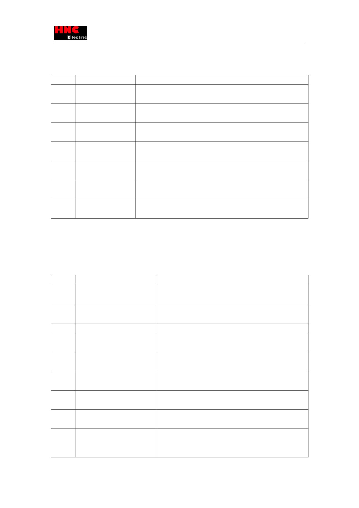
Note 2) Timing chart with no I/O input. The start will delay if vibration occurs.
Note 3) The start time varies from the different conditions.
Table 8.9.2 Operation procedures for home position return at servo ON
No.
Items
Description
1
Parameter setting for
Set the parameter of home position return speed, home position return creep
home position return
speed, home position return acceleration/deceleration time.
2
Confirm the start of home
Make sure MEND is in closed-circuit state, standby in the open-circuit state.
position return
3
Specify Point No.
After PCSEL1. . . 4 is open-circuit, specify points NO. 0. No need when start the
home position return by HOME.
4
Start of home position
After 10ms when input PCSEL1. . 4, change the PCSTART1 or HOME from the
return
open-circuit to closed-circuit.
5
Confirmation of command
Open-circuit from standby to MEND. If open-circuit, make the PCSTART or HOME
execution
to the open-circuit.
6
Confirmation of action
Confirm the action completion by MEND. When the MEND changes from
completion
open-circuit to closed-circuit, the action completed.
7
Confirmation of home
After action completion, confirm the home position return completion by HEND.
position return completion
When the HEND is closed-circuit, the home position return completed.
8.9.7 Detailed description for home position return
A) Home position return with arbitrary position
Home position return with the current position or Encoder phase Z near the current position.
■ Parameters
Table 8.9.4 Parameters of home position return with arbitrary position
No.
Parameter
Setting
645. 0
Base signal 1 selection for Home
Set “0 = Arbitrary position”
position
645. 1
Base signal 2 selection for Home
Set the Encoder phase Z to the base signal for home position
position
646. 0
Home position return direction
Set the direction for home position travel distance and Encoder phase Z
647. 1
Action at home position return
Selection of shifting to home position after detecting base signal for
completion
home position
649. 0
Home position return Creep speed
Set the speed after Encoder phase Z detection and home position return
completion
650. 0
Home position return
Set Acceleration/Deceleration time for Home position return
Acceleration/Deceleration time
651. 0
Home position Return
Set shift quantity from the position where the Base signal was detected
Shift-to-home-position quantity
to the home position
653. 0
Home position return Home position
Set a position at the time of home position return complete
data
657. 0
Home position return Phase Z
Set a distance from the positon where Base signal 1 for home position is
invalidation distance
detected to the position where Phase Z detection starts. This parameter
is needed when NO.645.1 =1
145
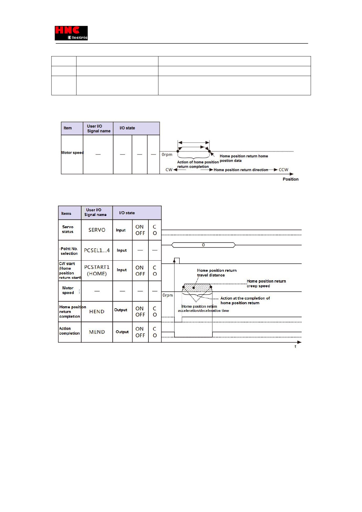
Table 8.9.5 Example for Parameters of home position return with arbitrary position
No.
Parameter name
Setting description
646. 0
Home position return direction
0=CCW
647. 1
Action at home position return
1=Move
completion
1) When not to use Encoder phase Z
Set “Base signal 2 selection for Home position” to “0=None”.
Figure 8.9.18 Overview diagram with horizontal axis(home position return with arbitrary position)
Note) I/O state: “C” indicates the closed-circuit for internal output circuit contact or external contact.
“O” indicates open-circuit.
Figure 8.9.19 Timing chart ((home position return with arbitrary position)
・When set the Action at home position return completion(No. 647. 1) to “No move”, it will not shift to the home position and
end the action.
2) When use Encoder phase Z
Set “Base signal 2 selection for Home position” to “1=Encoder phase Z”.
146
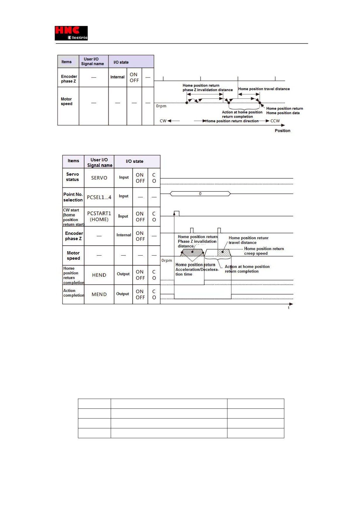
Figure 8.9.20 Overview diagram with horizontal axis(home position return with arbitrary position, encoder phase Z)
Note) ) I/O state: “C” indicates the closed-circuit for internal output circuit contact or external contact.
“O” indicates open-circuit.
Figure 8.9.21 Timing chart ((home position return with arbitrary position, Encoder phase Z)
・When set the Action at home position return completion(No. 647. 1) to “No move”, it will not shift to the home position and
end the action.
3) Home position return at servo OFF
The home position return with Move must be done at servo ON. But if meet the following conditions, the home position return
can be done at servo OFF.
Table 8.9.6
No.
Parameter
Setting value
645. 0
Base signal 1 selection for Home position
0 = Arbitrary position
647. 1
Action at home position return completion
0 = No move
657. 0
Home position return Phase Z invalidation distance
0
B) Home position return with Stopper
Home position return with the stopper or Encoder phase Z near the stopper.
■ Parameters
147
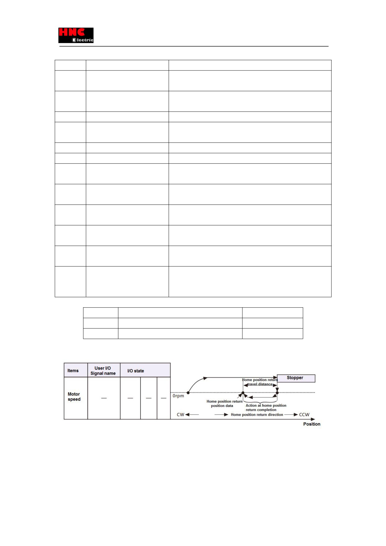
Table 8.9.7 Parameters for home position return with stopper
No.
Parameters
Setting
645. 0
Base signal 1 selection for Home
Set to “1 = Stopper”
position
645. 1
Base signal 2 selection for Home
Set the Encoder phase Z to the base signal for home position after
position
detecting Base signal 1
646. 0
Home position return direction
Set the direction of detecting stopper
647. 1
Action at home position return
Selection of shifting to home position after detecting base signal for
completion
home position
648. 0
Home position return Speed
Set the speed before press the stopper
649. 0
Home position return Creep speed
Set the speed after press the stopper
650. 0
Home position return
Set Acceleration/Deceleration time for Home position return
Acceleration/Deceleration time
651. 0
Home position Return
Set shift quantity from the position where the Base signal was detected
Shift-to-home-position quantity
to the home position
653. 0
Home position return Home
Set a position at the time of home position return complete
position data
655. 0
Home position return Press
Set the time at the time of press home position return
detection time
656. 0
Home position return Torque limit
Set Torque limit value at the time of home position return
value
657. 0
Home position return Phase Z
Set a distance from the positon where Base signal 1 for home position is
invalidation distance
detected to the position where Phase Z detection starts. This parameter
is needed when NO.645.1 =1
Table 8.9.8 Parameter setting for home position return with stopper
No.
Parameter
Setting value
646. 0
Home position return direction
0 = CCW direction
647. 1
Action at home position return completion
1 = Move
1) When not to use Encoder phase Z
Set “Base signal 2 selection for Home position” to “0=None”.
Figure 8.9.22 Overview diagram with horizontal axis(home position return with stopper)
148
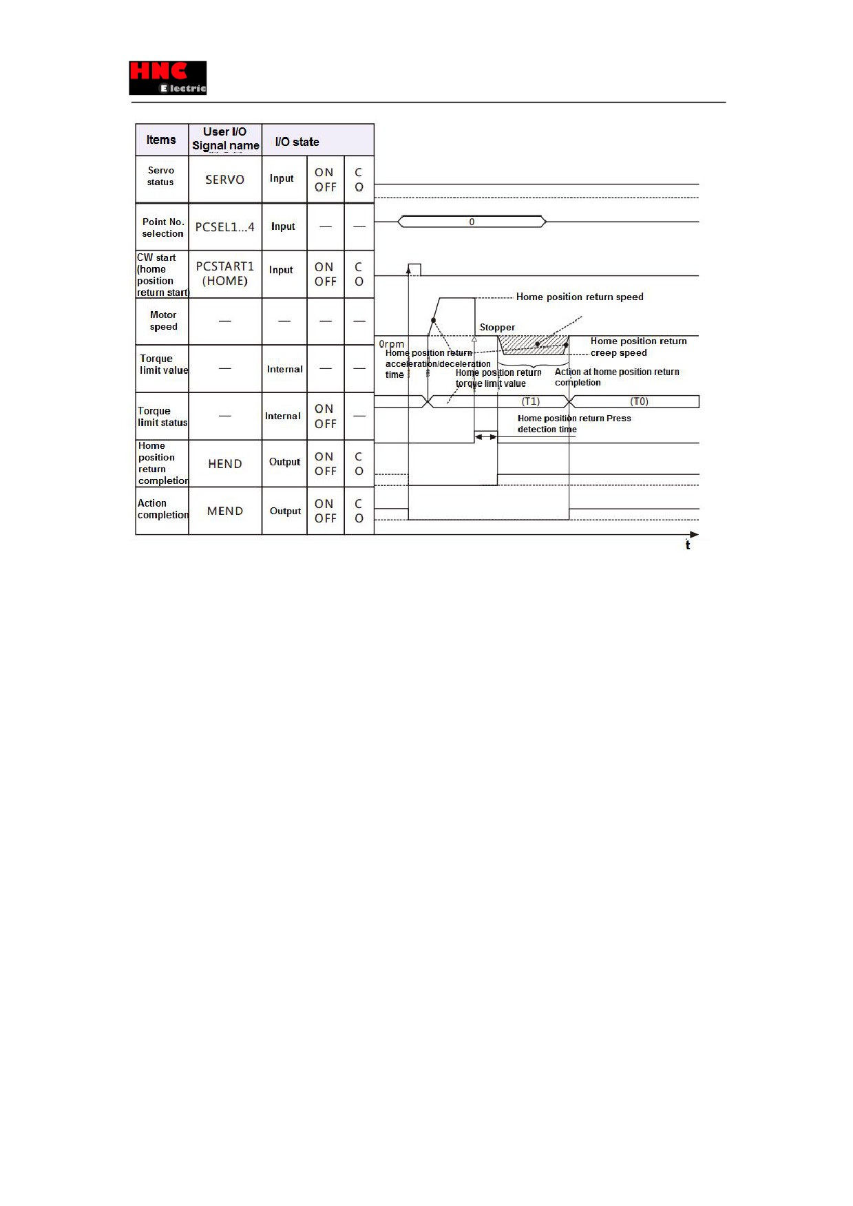
Note) ) I/O state: “C” indicates the closed-circuit for internal output circuit contact or external contact.
“O” indicates open-circuit.
Figure 8.9.23 Timing chart ((home position return with stopper)
・When set the Action at home position return completion(No. 647. 1) to “No move”, it will not shift to the home position and
end the action.
・Torque limit value(T0) returns to the normal setting after home position returns complete.
・The torque limit value from home position return starts to pressing detection time completion is the torque limit value of home
position return(No. 647. 0).
・The torque limit value(T1) from home position return pressing detection time completion to home position return completion
is the torque limit value for home position return when set the Home position return Torque limit option(No. 647. 0) to
“1=Enable”. If set to “0 = Disable”, the toque limit value will return to the normal setting.
・The home position return completed when confirm the position according to the stop position from outputting torque limit to
pressing detection time (No. 655. 0).
2) When use Encoder phase Z
Set “Base signal 2 selection for Home position” to “1=Encoder phase Z”.
149
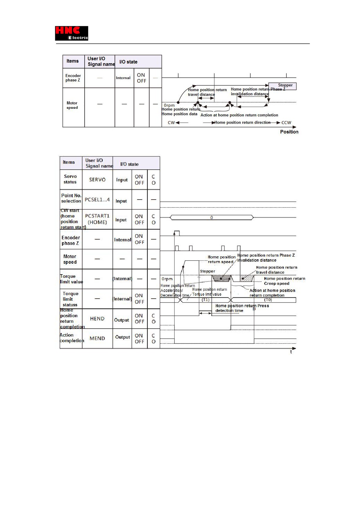
Figure 8.9.24 Overview diagram with horizontal axis(home position return with stopper and encoder phase Z)
Note) ) I/O state: “C” indicates the closed-circuit for internal output circuit contact or external contact.
“O” indicates open-circuit.
Figure 8.9.25 Timing chart ((home position return with stopper and encoder phase Z)
・When set the Action at home position return completion(No. 647. 1) to “No move”, it will not shift to the home position and
end the action.
・Torque limit value(T0) returns to the normal setting after home position returns complete.
・The torque limit value from home position return starts to pressing detection time completion is the torque limit value of home
position return(No. 647. 0).
・The torque limit value(T1) from home position return pressing detection time completion to home position return completion
is the torque limit value for home position return when set the Home position return Torque limit option(No. 647. 0) to
“1=Enable”. If set to “0 = Disable”, the toque limit value will return to the normal setting.
150
・The home position return completed when confirm the position according to the stop position from outputting torque limit to
pressing detection time (No. 655. 0).
C) Home position return with Home position DOG front end
Home position return with the Home position DOG front end or Encoder phase Z near the Home position DOG front end.
■ Parameters
Table 8.9.9 Parameters for home position return with Home position DOG front end
No.
Parameters
Setting
645. 0
Base signal 1 selection for Home
Set to “2 = Home position DOG front end”
position
645. 1
Base signal 2 selection for Home
Set the Encoder phase Z to the base signal for home position after
position
detecting Base signal 1
643. 0
Home position Base signal 1
Redetection of home position return creep speed after home position
redetection
return speed detecting home position DOG front end
646. 0
Home position return direction
Set the direction of Home position DOG front end from home position
sensor front end
646. 1
Home position sensor input polarity
Set Home position sensor input polarity
647. 1
Action at home position return
Selection of shifting to home position after detecting base signal for
completion
home position
648. 0
Home position return Speed
Set the speed before detecting home position DOG front end
649. 0
Home position return Creep speed
Set the speed after detecting home position DOG front end
650. 0
Home position return
Set Acceleration/Deceleration time for Home position return
Acceleration/Deceleration time
651. 0
Home position Return
Set shift quantity from the position where the Base signal was detected
Shift-to-home-position quantity
to the home position
653. 0
Home position return Home
Set a position at the time of home position return complete
position data
657. 0
Home position return Phase Z
Set a distance from the positon where Base signal 1 for home position is
invalidation distance
detected to the position where Phase Z detection starts. This parameter
is needed when NO.645.1 =1
Table 8.9.10 Parameter setting for home position return with Home position DOG front end
No.
Parameter
Setting value
643. 0
Home position Base signal 1 redetection
1=Enable
646. 0
Home position return direction
0 = CCW direction
646. 1
Home position sensor input polarity
0 = When OFF, detect Home
position dog front end
647. 1
Action at home position return completion
1 = Move
1) When not to use Encoder phase Z
Set “Base signal 2 selection for Home position” to “0=None”.
151
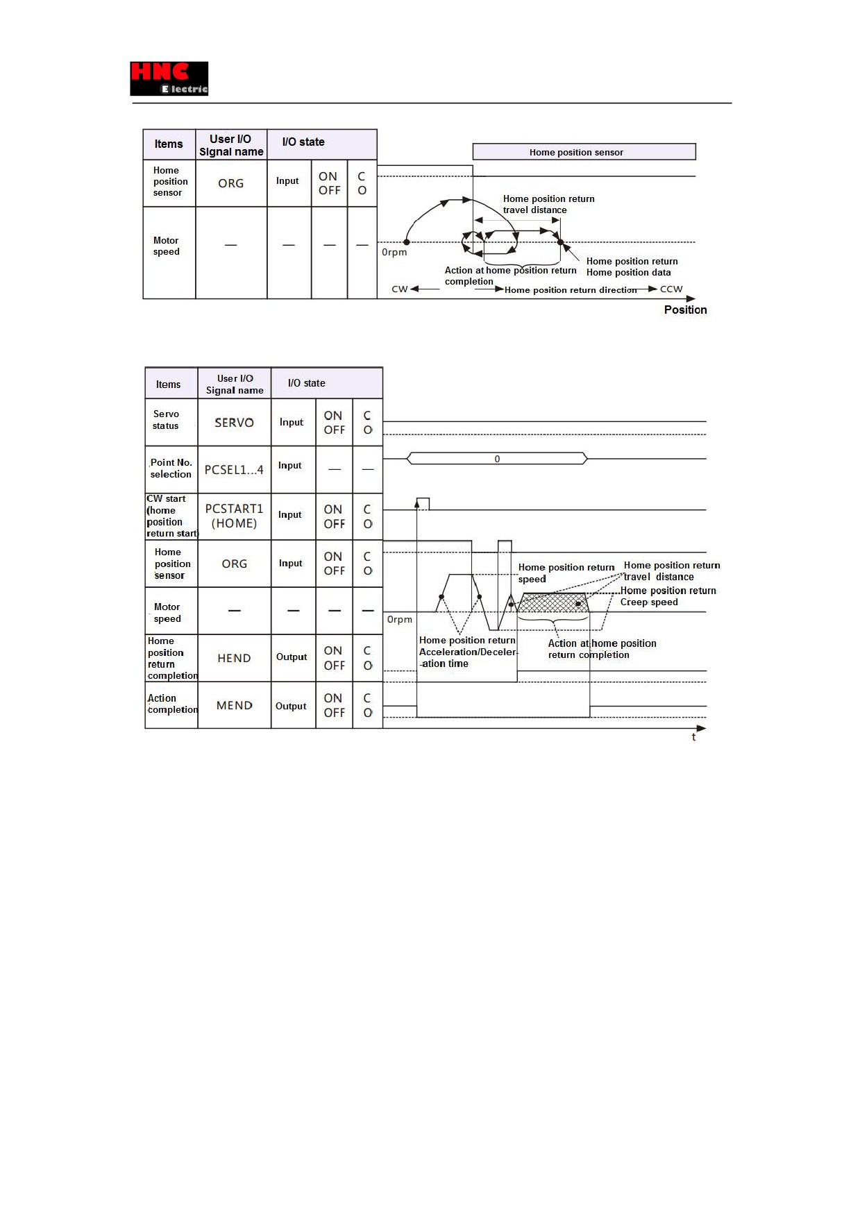
Figure 8.9.26 Overview diagram with horizontal axis(home position return with Home position DOG front end)
Note) ) I/O state: “C” indicates the closed-circuit for internal output circuit contact or external contact.
“O” indicates open-circuit.
Figure 8.9.27 Timing chart ((home position return with Home position DOG front end)
・When set the Action at home position return completion(No. 647. 1) to “No move”, it will not shift to the home position and
end the action.
・When set Home position Base signal 1 redetection (No. 645. 3) to “Disable”, no backward action for detecting home position
DOG front end.
・When start the home position return on the home position sensor, it will be back to home position DOG sensor front end and
have the home position DOG front end detection with home position return creep speed.
2) When use Encoder phase Z
Set “Base signal 2 selection for Home position” to “1=Encoder phase Z”.
152
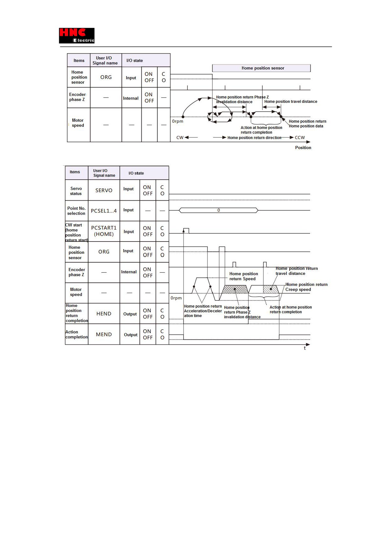
Figure 8.9.28 Overview diagram with horizontal axis(home position return with Home position DOG front end and phase Z)
Note) ) I/O state: “C” indicates the closed-circuit for internal output circuit contact or external contact.
“O” indicates open-circuit.
Figure 8.9.29 Timing chart ((home position return with Home position DOG front end and phase Z)
・When set the Action at home position return completion(No. 647. 1) to “No move”, it will not shift to the home position and
end the action.
・When set Home position Base signal 1 redetection (No. 645. 3) to “Disable”, no backward action for detecting home position
DOG front end.
・When start the home position return on the home position sensor, it will be back to home position DOG sensor front end and
have the home position DOG front end detection with home position return creep speed.
3) About the exit of home position DOG sensor
Set the「Base signal 1 selection for Home position( No. 645. 0)
」 to “2 = Home position DOG front end”.
When the start point of home position return is on the home position DOG sensor, back to the position where the home
position return can proceed to start the home position return. Take it as the example with “set「Base signal 2 selection for
Home position(No. 645. 1)」to “1 = Encoder Phase Z”.
153
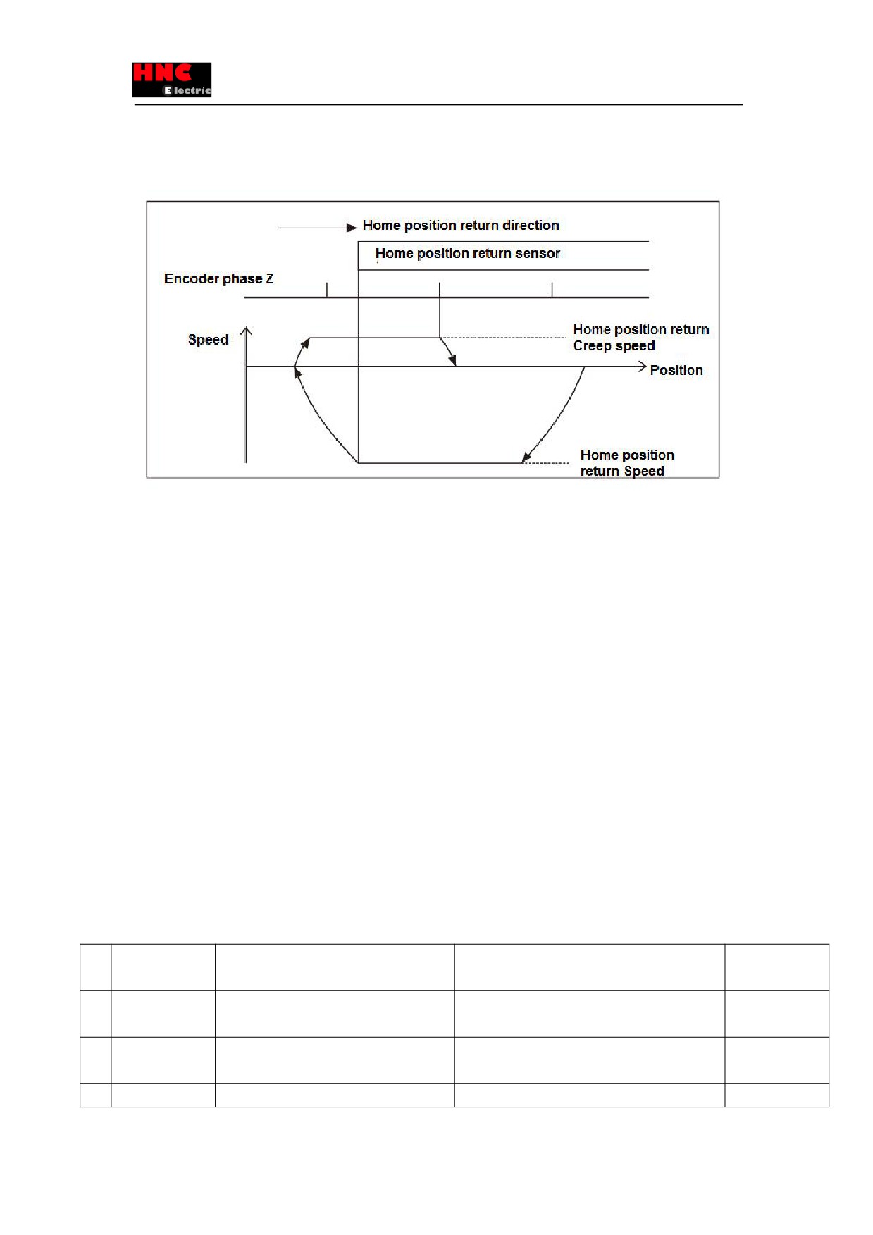
No matter how to set 「Home position Base signal 1 redetection(No. 645. 3)」, it will back and perform the creep operation.
Move in the opposite direction of the home position return and exit from the home position DOG sensor, CCW, and move at
the home position creep speed. Redetect the home position DOG front end.
Figure 8.9.30 Exit of home position DOG sensor( The setting of the “Home position Base signal 1 redetection” is invalid)
9. Troubleshooting and countermeasures
9.1 Alarm display
When the alarm occurs, the alarm description can be confirmed according to the alarm code on the panel of servo drive. The
alarm code and alarm description are shown in the 「Warning list」.
If you want to consult with HNC ELECTRIC Corporation, make a record of the alarm and contact with us.
9.2 Alarm handling and alarm reset
For alarm handling and resetting, please refer to “Warning List”. There are three ways for alarm reset. It varies according
to different alarm items.
① The host control device sends reset clear signal
(RESET of CN1 5pin)to the drive..
② Restart drive control power supply.
③ Press SHIFT+UP at the same time.
Table 9.2.1
No
Alarm
Description
Handling ways
Reset method
0
System alarm
Control circuit error
Consult HCFA distributors.
Restart
control
・ CPU in control circuit cannot work normally.
power supply
1
EEPROM data
・ Parameter writing error
After confirming cables, rewrite the parameters.
Reset
error
2
Model code error
The model code cannot be read normally.
・ Check the combination of motor and drive.
Restart
control
154

・ The combination of motor and drive is
・ Please Check the encoder cable.
power supply
incorrect.
・ The encoder cable does not connect to the
drive correctly.(including disconnect).
4
Overspeed error
・ Motor rotates exceeding the max. speed
・ Please adjust the parameters.
Reset
・ Inappropriate command from upper
・ Check the command
controller
・ Check if the limit sensor position changes.
・ Accumulated pulses maybe caused by
「drive restriction」
5
Speed deviation
Position control and speed control error
・ Check the command from the upper controller
Reset
error
・ Inappropriate command
・ Adjust gain parameter
・ Overload, cannot catch up with the
・ Check the setting value of Speed deviation error
command speed
detection value(No.90.0).
・ Speed deviation error
detection
・ Check if the brake has been released
value(No.90.0) is incorrect
・ Check whether the torque limit operates or not
6
Position deviation
Position control error
・ Adjust gain parameter
Reset
error
・ The acceleration time is too short
・ Check the command from the upper controller
・ The power cable or encoder cable wiring
・ Check the wiring
error or disconnect
・ Check the setting value of Position deviation error
・ Position deviation error Detection value
Detection value (No.87.0)
(No.87.0) is incorrect
・ Check if the brake has been released
・ Check whether the torque limit operates or not
7
Overload error
Position control error after operation starts:
Continuous operation can cause overload or burn
Reset
1. The motor does not operate
the motor.
2. Motor operates for a short time
1&2.・ Check the motor power cable wiring
3.Alarm occurs after operation starts
3.
・ Check the selected motor capacity
In operating
・ Check if the brake has been released
4.In operating, alarm occurs at the same
・ Check the reduction ratio
period
4.
・ Check the acceleration time, torque
The acceleration time is too short or no
waveform , load rate [in acceleration]
acceleration. (bump into other objects)
・ Check there are no obstacles to the driving
5,Motor capacity is too small /too heavy load
range [Outside the acceleration]
6. Excessive vibration
5.
・ Check the torque waveform and load rate
7.Control gain or command not correct(CCW
・ Check the inertia ratio
rapidly)
→Install the reducer to improve the motor capacity
8.Noise occurs
6&7.・ Adjust gain parameter
・ Check if there are rapid CCW in command
・ Use command smoothing filter
8.
・Use notch filter and low-pass filter to suppress
the noise
8
Command
Position control error
・ Check Command division and multiplication
Reset
overspeed error
・Position command input exceed max. speed
(No.34.0、No.36.0)
・ The command from upper controller is
・ Check the command from upper controller
inappropriate.
155

9
Encoder
pulse
・ Encoder pulse output frequency exceeds
・ Check the value of Encoder pulse output Division
Restart
control
output frequency
4Mpps
and multiplication(No.276.0, No.278.0)
power supply
error
・ Check the encoder pulse output frequency upper
limit value(No.285.0) and error detection delay time
(No.286.0)
10
Internal
positon
・ Internal position command outside the range
・ Adjust the overflow detection (No.643.0)
Reset
command
(±1,073,741,823)
・ Adjust the travel distance
overflow
error/
・ Travel distance of the command outside the
・ Adjust the parameters for home position return
home position
range (±2,147,483,647)
return failure
・ Home position return failure or timeout
11
Encoder
error
・Multi-rotation data of the encoder outside the
・ Check the setting in Selection of an encoder
Restart
control
(multi-rotation
range of ±32,767
system(No.257.0)
power supply
counter overflow )
・ Make sure the multi-rotation travel distance is
within ±32,767
12
Overheat error
・ Temperature of control circuit exceeds the
・ Check the setting and environment of the drive
Reset
upper limit
・ The ambient temperature of drive should be in
accordance with
「 Installation direction and
clearances」
14
Overvoltage error
・ Main circuit voltage exceeds the upper limit
Only under the occasion of deceleration
Reset
of drive circuit
・ Confirm the regenerative resistor warning on the
setting panel and install the regenerative resistor if
necessary.
・ Check the operation mode of command
・ Use filter to slow down the deceleration
Not only for the occasion of deceleration
・ Check whether the main circuit voltage is outside
the specified range
・ Check if the voltage changes when driven
15
Power
supply
Main circuit voltage too high or too low
Under the occasion from servo ON to start operating
Reset
error (main circuit
・ Do not enter the main circuit power
・ Check the main circuit power to the drive
power)
・ Main circuit power outside the specified
・ Check the main circuit power voltage
range
・ Check the timing of main circuit power ON and
・ Main circuit voltage change outside the
SVON signal input
specified range
Under the occasion of operating
・ Input SVON signal without main circuit
・ Check if the voltage changes by the overall
power
operation of the device. And use the sufficient power
Action time of regenerative control circuit
supply to avoid the voltage changes.
outside the specified range
Under the occasion of deceleration
・ Continuous regeneration ON
・ Confirm the regenerative resistor warning on the
setting panel and install the regenerative resistor if
necessary.
・ Check the operation mode of command
・ Use filter to slow down the deceleration
16
Encoder
error
・ Encoder data changes sharply in a short
・ Check if there’s the wire breakage or pins off
Restart
control
156

(data receive)
time
・ Use the cable at a length of less than 20m
power supply
17
Encoder error (No
・ Encoder communication interrupts
・ Check the disturbance by the noise
response)
-Use shielded twisted pair cable
19
Encoder
error
・ Cannot communicate with the encoder
-Separate encoder cable from the power cable
(communication)
-Connect FG
20
Encoder
error
・Multi-revolution data of the absolute encoder
-Install a filter ring to the power cable and encoder
(Multi-revolution
changes sharply in a short time
cable
data)
・ Multi-revolution data of the encoder cannot
・Consult HCFA distributor if have not been improved
receive the communication
18
Encoder
・ The battery voltage of absolute encoder
When use absolute system
Restart
control
error(circuit)
drops or battery removed (Alarm of items 21
・ Change the battery and initialize the encoder
power supply and
occurs)
When using absolute system
encoder clearing
・ Outside the specification and temperature
When not use absolute system
range of encoder, the output data error
・ Check if outside the specification and temperature
・ Encoder itself error
range of encoder,
・Consult HCFA distributor if have not been improved
21
Encoder
error
・ Battery voltage is too low
・ Check if the battery voltage drops
Restart
control
(voltage drops)
・ Battery drops
・ Check if the battery and cable removed
power supply and
・ When the battery is connected for the first
・ Initialize the encoder
encoder clearing
time
22
Power
supply
・ Voltage of control power drops
・ Check the control power voltage
Reset
error
(control
・ Check the power capacity
power)
・ Check the 24V ( 1pin,2pin ) wiring of user I/O
connector
Alarm No.15(power error) or other alarms may occur
simultaneously. Please check all the alarms.
23
Switching
・ Control circuit error
・ Consult HCFA distributor
Reset
circuit error
24
Overcurrent error
・ Motor current error detected by drive
・ Check the motor power cable
Reset
-Grounding or not
-Power cable wiring
・ Check the control gain and operation mode
-Increase acceleration/deceleration time
-Set the command smoothing filter ((No.66.0,
No.66.1, No.80.0,No.81.0)
・ Release the brake and stopper to make the motor
operate
・ Check the encoder cable
-Wiring(bad contact)
-Use shielded twisted pair cable
・ Consult HCFA distributor if have not been
improved
25
Inverter error 1
・ Control circuit error
・ Check the motor power cable
Reset
157
26
Inverter error 2
・ Control circuit error
-Grounding or not
・ Servo ON timeout
-Power cable wiring
・ Consult HCFA distributor if have not been
improved
27
Current
sensor
・ Ambient temperature of current sensor is too
・ Check the setting and temperature of the drive
Reset
error
high
・Consult HCFA distributor if have not been improved
・ Current sensor error
29
Power
error
・ Control power supply (DC5V) voltage drops
・ Check if short-circuit on the encoder cable wiring
Reset
(Inside the drive)
in the drive
・ Consult HCFA distributor if have not been
improved
9.3 Troubleshooting
When no alarm occurs, confirm the following items if the drive does not operate and the motor does not rotate.
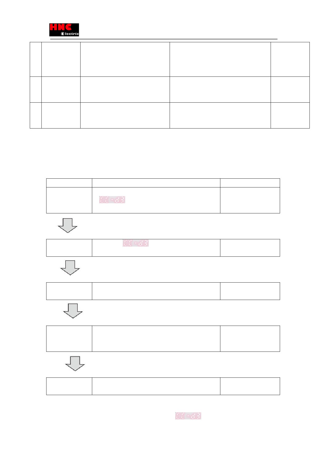
Figure 9.3.1
Status
Description
Reference items
Troubleshooting 1
Switch on the control power supply (24V DC), but on any display
Table 9.3.1
No display on setting
「
」on the setting panel.
panel
Troubleshooting 2
Table 9.3.2
Even though 「
」is displayed on the setting panel, the
Servo not ON
servo cannot start.
Troubleshooting 3
The servo is ON, but the motor will not operate.
Table 9.3.3
Motor cannot rotate
Troubleshooting 4
The motor operates unsteadily.
Table 9.3.4
Motor operation not
steady
Troubleshooting 5
Vibration and sound occurs when the motor operates.
Table 9.3.5
Vibration and sound
■Troubleshooting 1 (No display on setting panel)
Switch on the control power supply (24V DC), but on any display of「
」on the setting panel.
158
Table 9.3.1
Cause
What to do
The user I/O connector is not connected to 24V
Connecting 24V DC to the user I/O connector.
DC.
Pin1 and 3 is connected to 24V DC. Pin2 and 12 is connected to GND.
The user I/O connector loosens.
Check the connection and make sure it’s OK.
24V DC voltage drops.
Check the capacity of 24V DC.
Drive itself failure.
Consult with CCSERVO Corporation.
■Troubleshooting 2 (Servo not ON)
Even though 「
」is displayed on the setting panel, the servo cannot start.
Table 9.3.2
Cause
What to do
There is no servo ON(SVON) signal input.
Input SVON signal of host control device to the user I/O connector.
Alarm No.15 occurs.
Make sure CHARGE LED is ON. If not, check if the 200V AC input
There is no 200V AC input.
connector(L1/L2) is loosen or the 200V AC is output or not.
Alarm No.15 occurs.
Connect the main circuit power supply.
There is no main circuit power input in
multi-axial drive.
The motor power output connector (U/V/W)
Check the connection and make sure it’s OK.
loosen.
Make sure if it’s connected in accordance with the connector installing
method in the user’s manual.
Drive itself failure.
Consult HCFA Corporation distributor
■Troubleshooting 3 (Motor cannot rotate)
The servo is ON, but the motor will not operate.
Table 9.3.3
Cause
What to do
Wrong parameter setting.
For setting all the basic parameters in all control modes, refer to chapter 8
「Table 8.2.4, Table 8.3.2, Table 8.4.2 and Table 8.5.2」.For position control
mode and internal position command mode, refer to 「Appendix 2 SV-E3
Positioner function」.
The connection of user I/O connector is not
For correct connection, refer to 「Figure 8.2.1, Figure 8.2.2, Figure 8.2.3,
correct.
Figure 8.3.1, Figure8.4.1 and Figure 8.5.1」..For position control mode and
internal position command mode, refer to 「Appendix 2 SV-E3 Positioner
function」.
Command input is restricted.
Disconnect the HOLD and COM- of user I/O connector.
Torque command limit setting is not correct.
Set parameter No.147.0 and 148.0 correctly when using torque command
limit.
CCW/CW drive restriction input becomes
Set the parameter No.67.0 to 「0」 when not using CCW/CW drive
effective.
restriction input. CCWL, CWL and COM- of user I/O connector should be
closed when using CCW/CW drive restriction input.
159