SERVO DRIVE SV-E3 SERIES. INSTRUCTION MANUAL (v1.5) - page 6
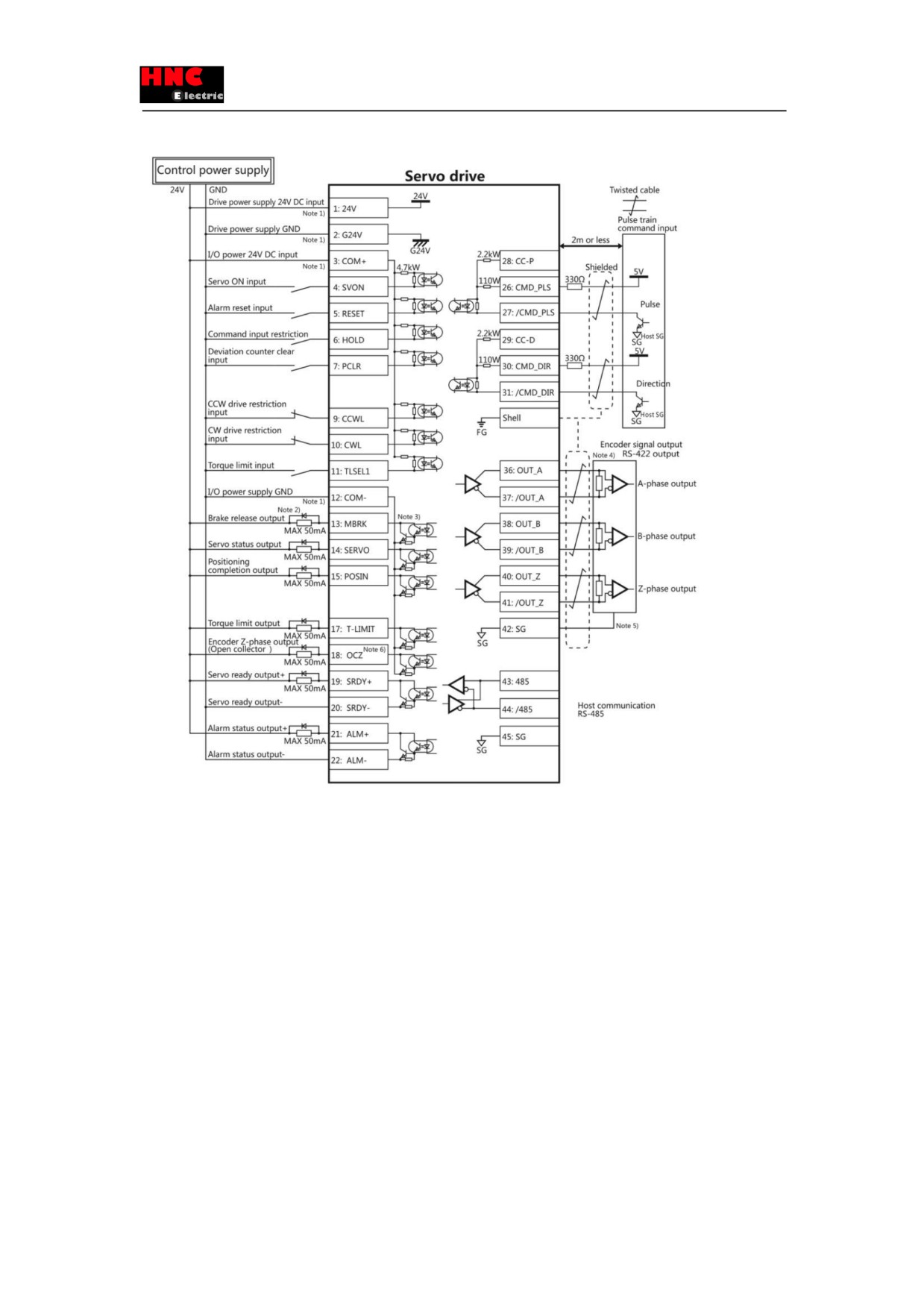
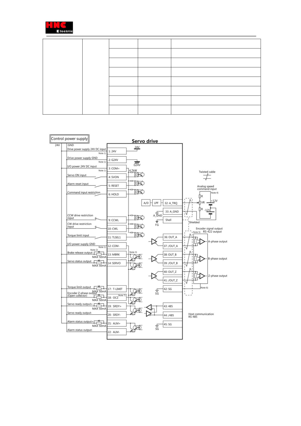
Note 1)Control power supply(24V, G24V) and I/O power (COM+, COM-) share the same power supply(For the models of
750W or less).
Note 2)If there is drive inductive load(relay), please use protective circuits(diode).
Note 3) Transistor output is an open collector output circuit of the Darlington-connected. It should be connected with relay or
optocoupler. Please don’t connect transistor directly because the voltage VCE(SAT) between collector and emitter is about
1V which cannot meet the required voltage VIL of TTL IC when transistor is ON.
Note 4) Terminal resistance must be connected as shown in the wiring diagram.
Note 5) Connect the signal ground on the host control device of output signal of the encoder. The connection of signal ground
and power supply GND may cause malfunction.
Note 6) If the pulse width of Z-phase is too narrow to identify the host control device, please reduce the encoder pulse output
division and multiplication No.276.0, 278.0 or reduce the speed to increase the pulse width.[Pulse width]=1/speed/(division
and multiplication×217).
8.2.4 Setting of basic parameter (Pulse position command input)
100
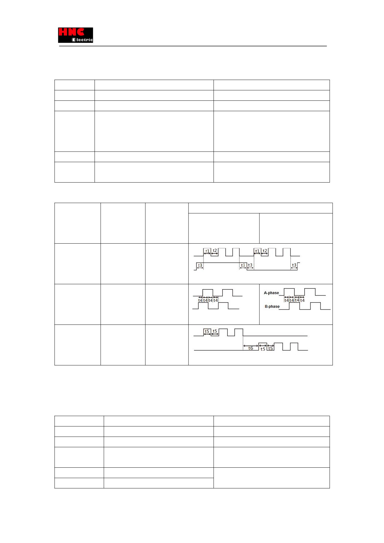
The factory setting is 「Pulse position command input」. It is necessary to set the following parameters if the drive is driven by
pulse position command input.
Table 8.2.4 Parameter of control mode (Pulse position command input)
Parameter No.
Parameter
Operation · Value
2.0
Control mode selection
Set to “0”.
3.0
Command mode selection
Set to “1”.
32.0
Pulse command input mode
Select one in the following (Note 1)
“0”: Pulse / direction
“1”: Orthogonal phase difference
“2”: CCW/CW
34.0
Command division and multiplication (Numerator)
Set to “32768”(Note 2)
36.0
Command division and multiplication (Denominator)
Set to “(The number of output pulse of host control
mode)/4” (Note 2)
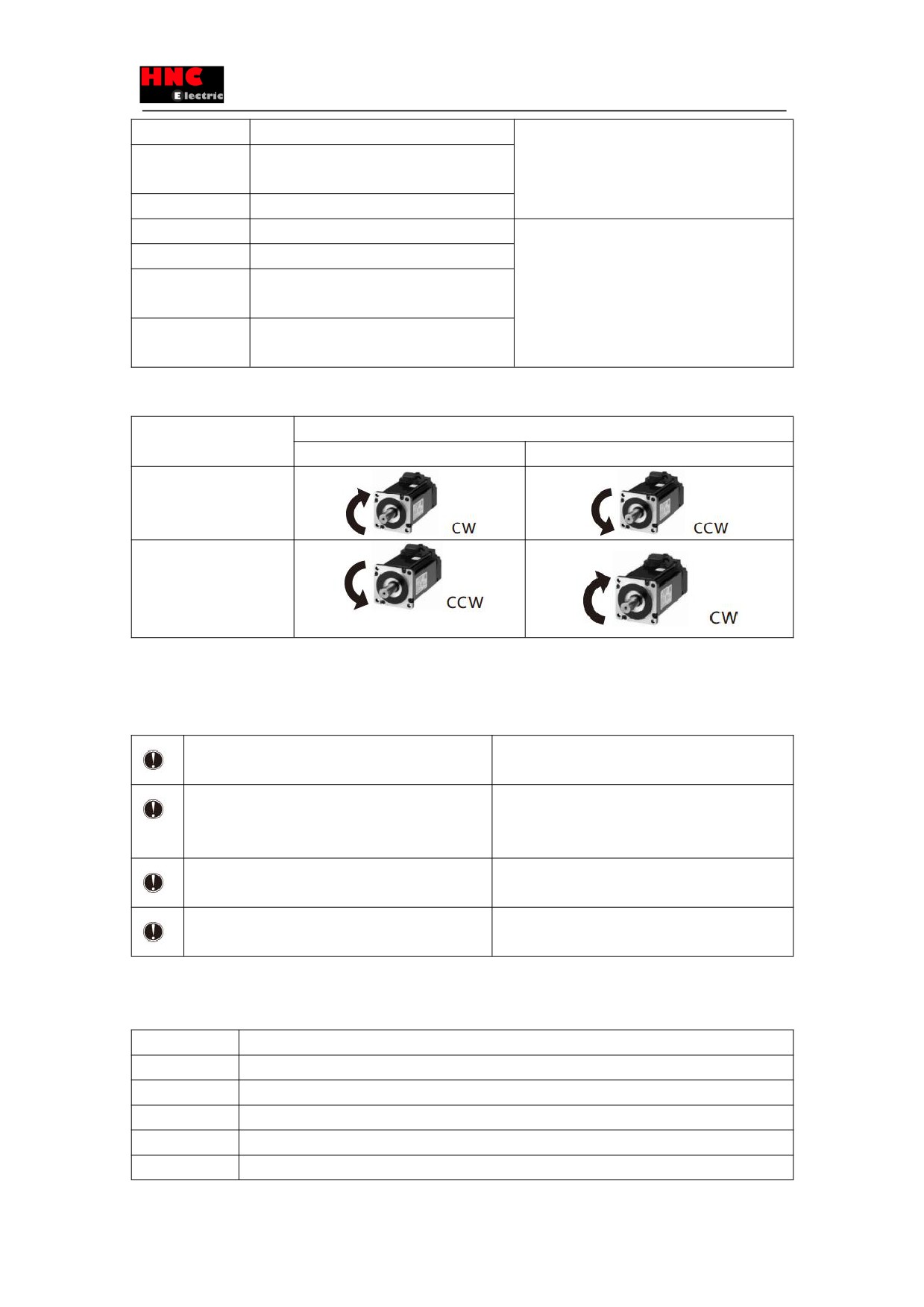
Note 1: Pulse command input list is shown in the following table.
Table 8.2.5 Pulse command input list
Parameter
Input signal
Signal name
The minimum necessary time range (t1, t2, t3, t4, t5, t6)
No.32.0 pulse
Positive direction
Negative direction
command input
mode
0
Pulse · direction
Pulse
(Initial value)
Command pulse
CMD_PLS
Direction
CMD_DIR
1
AB-phase
A-phase
orthogonal phase
CMD_PLS
pulse
B-phase
CMD-DIR
2
Positive direction
CCW CMD-PLS
pulse
CW CMD-DIR
Negative
direction pulse
Note 2: Set when 1-rotation pulse (131,072) of host control device and drive is different. For details, refer to
「Chapter
4
Parameter list」.
Set the following parameters according to the using status.
Table 8.2.6 Parameter for pulse train position command input
Parameter No.
Parameter
Description
32.1
Pulse train command input Rotation direction
For details, refer to 8.2.7.
32.3
Selection of Pulse train input logic
Select the logic of pulse train
33.0
Pulse train command - Input filter selection
Reduce the misoperation caused by input
command pulse interference.
64.0
Positioning completion determination method
Specify the conditions of positioning completion.
68.0
Positioning completion range
101
69.0
Positioning completion speed
70.0
Positioning completion Pulse train command
input (speed)
71.0
Positioning completion Detection delay time
66.0
Position command smoothing filter 1 selection
Set the damping filter.
66.1
Position command smoothing filter 2 selection
Suppress the resonance of device when the
80.0
Position command smoothing filter 1 Moving
acceleration/ deceleration command is too high or
average order
positioning.
81.0
Position command smoothing filter 2 Moving
average order
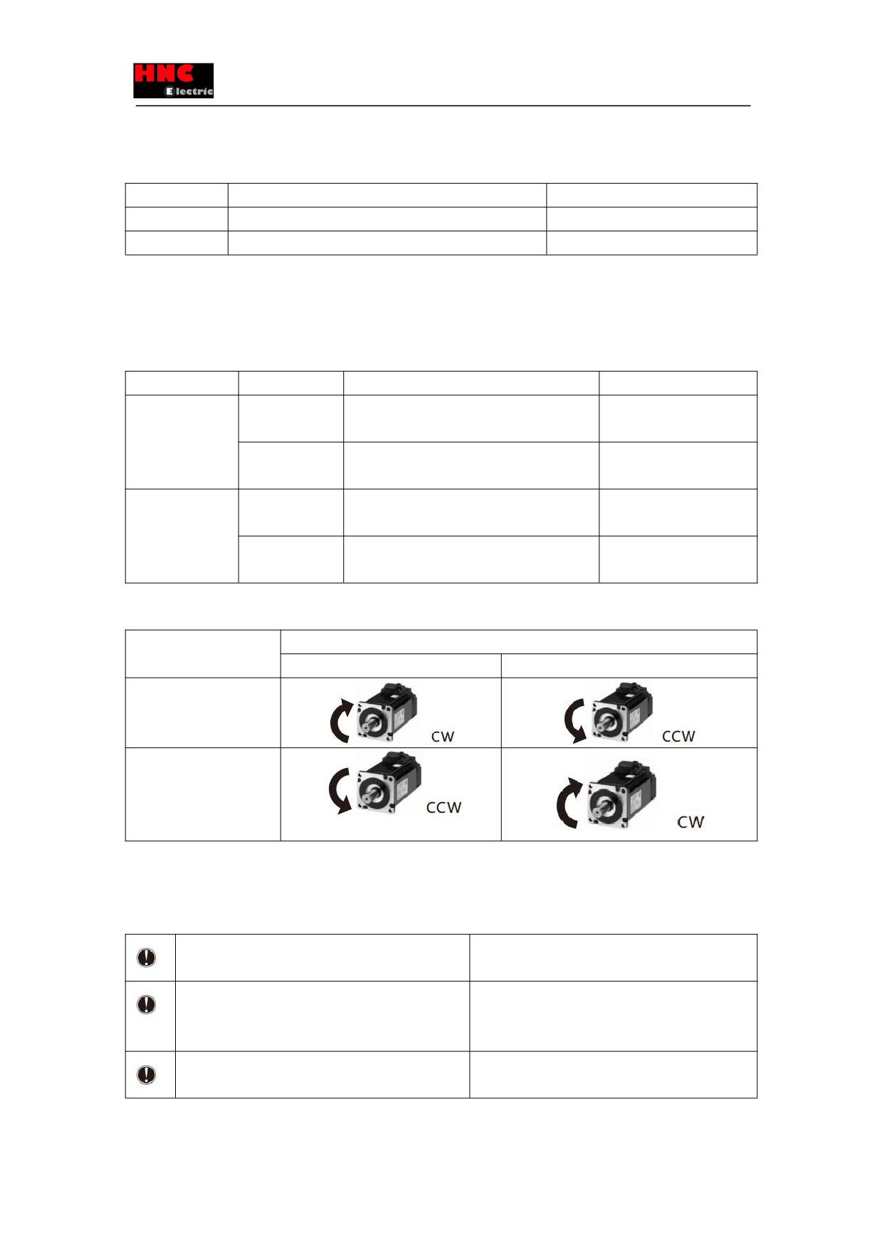
Table 8.2.7 The setting of parameter 32.1 and the rotation direction of motor (Pulse train position command input)
Value of parameter 32.1
Command pulse of host control device
Positive direction
Negative direction
0
1
[Initial value]
The basic parameter and operation parameter can be set by the [Set panel].
8.2.5 Test run (Pulse train position command input)
■Before test run
Table 8.2.8
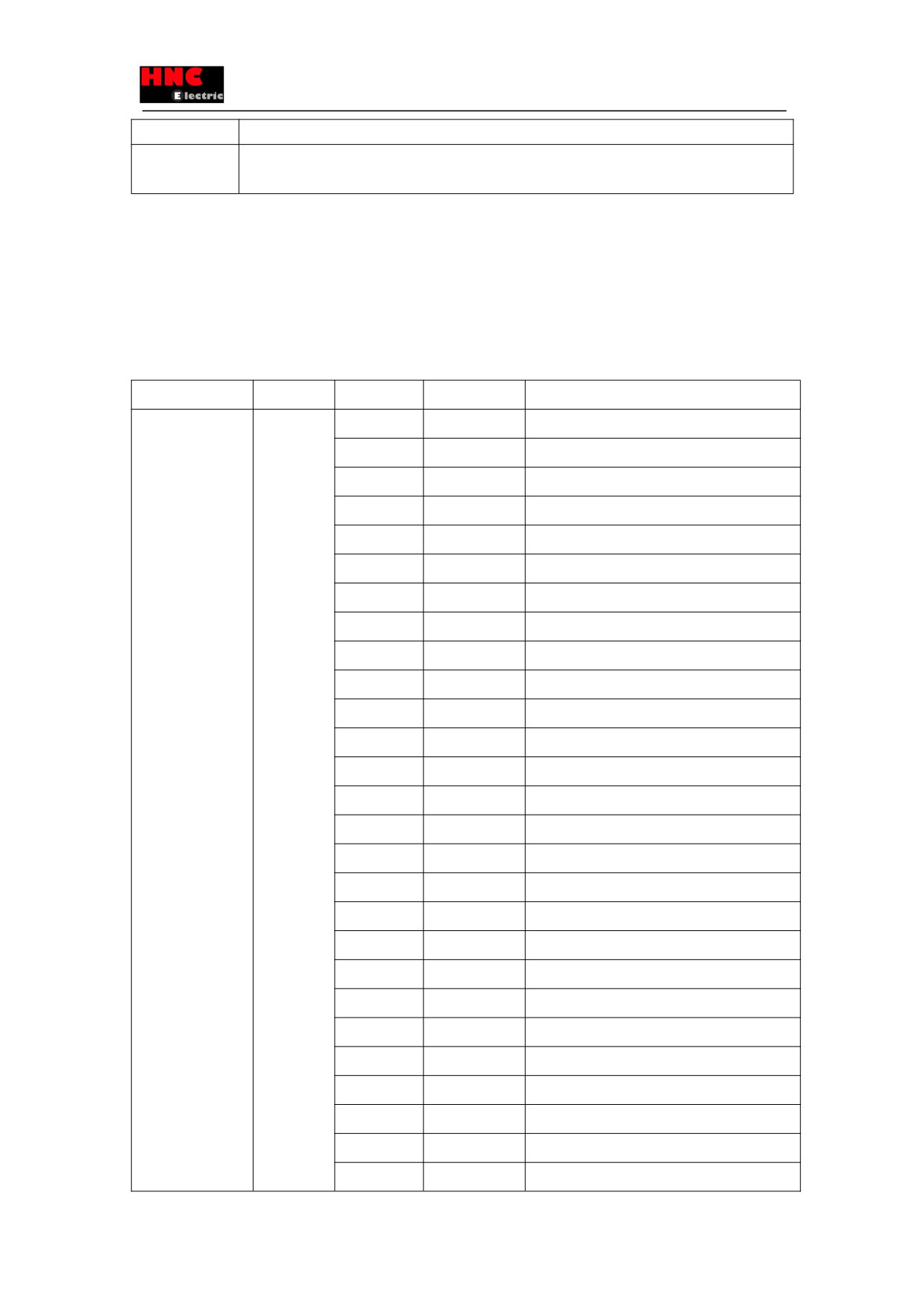
Make sure all the wiring are connected properly before
To prevent electric shock, fire, malfunction and injury.
switch on the power to the drive and motor.
Test run after setting the basic parameters.
If set the wrong basic parameters, the motor will not
run, run unsteadily or lose control, which may cause
some injury or accidents.
Confirm the operation of the motor alone first before test
The unexpected movements, such as unstable action
run. (Remove the other connection to the mechanics.)
or lose control, may cause tome injury or accidents.
Drive the motor after release the brake on the motor if
If not, it may cause the malfunction to the brake and
the motor is attached with the brake.
motor.
■Test run
Table 8.2.9 Steps for test run (Pulse train position command input)
Steps
Operation
1
Make sure all the wiring are connected properly.
2
Switch on the power to the drive.Note1)
3
Switch on the main circuit power to the drive(200V AC).
4
Make the SVON input of drive ON to start the motor excitation. (Connect the I 1 terminal to the COM-)
5
Input position command pulse at a relatively low speed from host control device to make the motor run at
102
a low speed(100r/min). Make sure the rotation direction of the motor is same to the setting direction.
6
Improve the position command pulse frequency gradually after confirming the safe implementation of
actual operation. Then confirm the operation until it comes to the specified speed.
Note1: The control power supply for the models of 750W or less are supplied by external 24V DC. 1kW or more are supplied
from internal. So the control power supply of models of 1kW or more can be ON or OFF by switching on or cutting off the main
circuit AC power.
8.3 Speed control mode (Analog speed command input)
8.3.1 Wiring for user I/O connector(CN1) (Analog speed command input)
Name
Symbol
Pin No.
Signal name
Contents
User I/O
CN1
1
24V
Drive control power supply 24V input
●24V power
2
G24V
Drive control power supply GND
supply input
3
COM+
I/O power supply 24V input
●Parallel I/O
4
SVON
Servo ON input
●Pulse command
5
RESET
Alarm reset input
input
6
HOLD
Command input restriction(Zero speed clamp)
●ABZ output
7
-
Reserved
8
-
Reserved
9
CCWL
CCW drive input restriction
10
CWL
CW drive input restriction
11
TLSEL1
Torque limit input
12
COM-
I/O power supply GND
13
MBRK
Brake release output
14
SERVO
Servo status output
15
-
Reserved
16
-
Reserved
17
T-LIMIT
Torque limit output
18
OCZ
Encoder Z-phase output (open collector)
19
SRDY+
Servo ready output +
20
SRDY-
Servo ready output -
21
ALM+
Servo alarm output+
22
ALM-
Servo alarm output-
23
NC1
Reserved (Disconnected)
24
-
Reserved
25
-
Reserved
26
-
Reserved
27
-
Reserved
103
28
-
Reserved
29
-
Reserved
30
-
Reserved
31
-
Reserved
32
A SPEED
Analog speed command input
33
A_GND
Analog speed command input ground
34
-
Reserved
35
-
Reserved
36
OUT_A
Encoder A phase output
37
/OUT_A
Encoder /A phase output
38
OUT_B
Encoder B phase output
39
/OUT_B
Encoder /B phase output
40
OUT_Z
Encoder Z phase output
41
/OUT_Z
Encoder /Z phase output
42
SG
Signal ground
43
485
EIA-485 communication data
44
/485
EIA-485 communication /data
45
SG
Signal ground
46
NC2
Reserved(Disconnected)
47
-
Reserved
-
48
Reserved
-
49
Reserved
50
-
Reserved
104
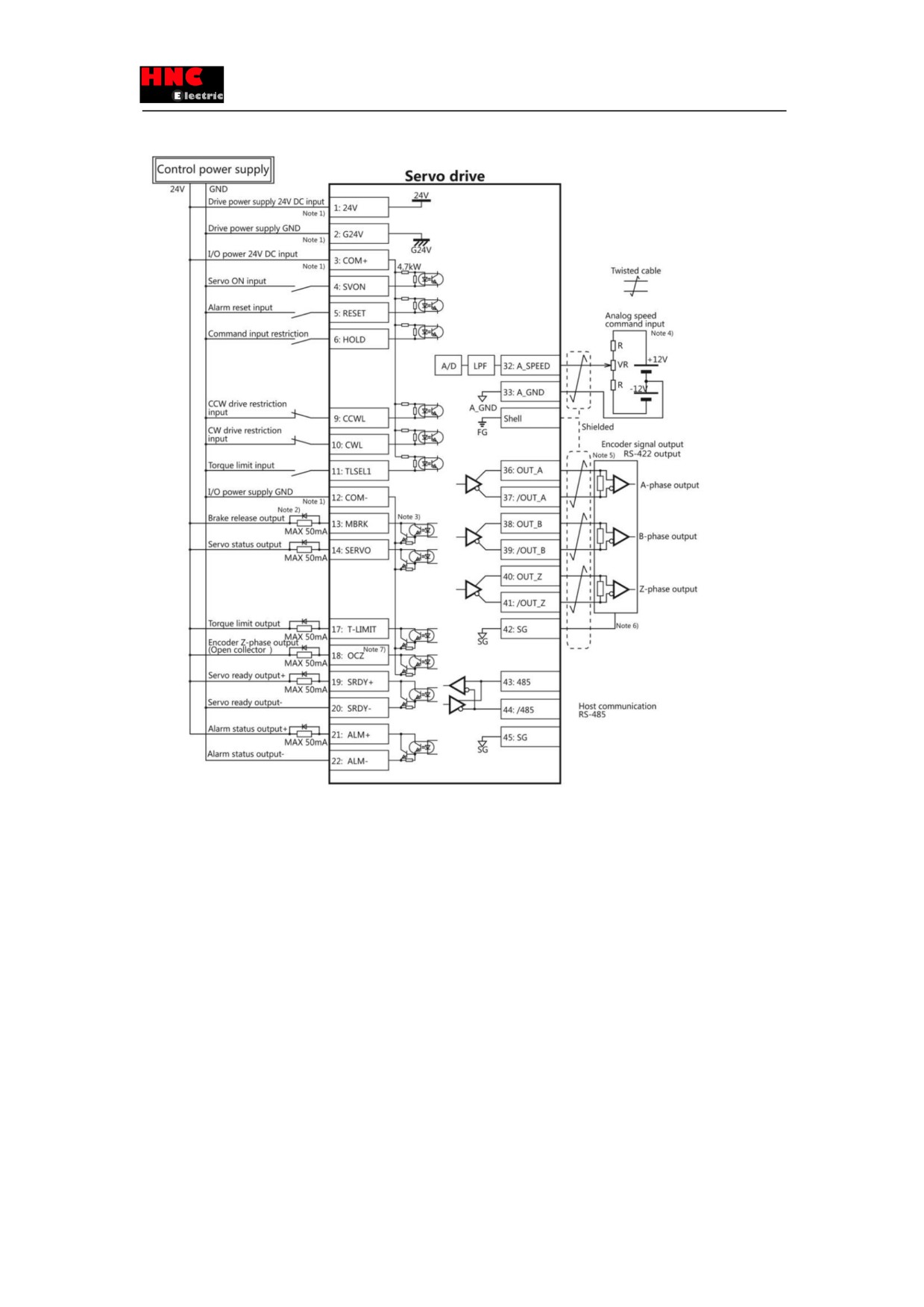
Note 1)Control power supply(24V, G24V) and I/O power (COM+, COM-) share the same power supply(For the models of
750W or less).
Note 2)If there is drive inductive load(relay), please use protective circuits(diode).
Note 3) Transistor output is an open collector output circuit of the Darlington-connected. It should be connected with relay or
optocoupler. Please don’t connect transistor directly because the voltage VCE(SAT) between collector and emitter is about
1V which cannot meet the required voltage VIL of TTL IC when transistor is ON.
Note 4) Terminal resistance must be connected as shown in the wiring diagram.
Note 5) Terminal resistance must be connected as shown in the wiring diagram.
Note 6) Connect the signal ground on the host control device of output signal of the encoder. The connection of signal ground
and power supply GND may cause malfunction.
Note 7) If the pulse width of Z-phase is too narrow to identify the host control device, please reduce the encoder pulse output
division and multiplication No.276.0, 278.0 or reduce the speed to increase the pulse width.[Pulse width]=1/speed/(division
and multiplication×217)
8.3.2 Setting of basic parameters (Analog speed command input)
105
Set the basic parameters.
The following parameters must be set if the drive needs to be driven by analog speed command input.
Table 8.3.2 Parameter of control mode change(Analog speed command input)
Parameter No.
Parameter
Description
2.0
Select control mode.
Set to “1”.
3.0
Select command mode.
Set to “2”.
The parameters from [48. 0] to [78. 0] in the following table can be selected according to the actual usage.
Table 8.3.3 Parameter of analog speed command input
Parameter No.
Parameter
Description
48.0
Analog speed command input -Filter constant(Numerator)
Filter out the input command voltage
49.0
Analog speed command input -Filter constant(Denominator)
interference. Use it with parameter 62.1.
50.0
Analog speed command input -Gain (Numerator)
Set the speed at the maximum command
51.0
Analog speed command input -Gain (Denominator)
input voltage (±10V). (Note 1)
52.0
Analog speed command CCW speed limit override value
Set speed limit value at CCW
(Numerator)
rotation.(Note 2)
53.0
Analog speed command CCW speed limit override value
(Denominator)
54.0
Analog speed command CW speed limit override value
Set speed limit value at CW
(Numerator)
rotation.(Note 2)
55.0
Analog speed command CW speed limit override value
(Denominator)
60.0
Analog speed command
- Fixed offset value
The motor speed is 0[ r/mi n] by
adjusting the command input to 0V. Use
it with parameter 62.2.
62.0
Analog speed command
- Rotational direction
For details, refer to table 5.3.4.
62.1
Analog speed command
- Selection of input filter
Please use it with parameter 48.0 , 49.0.
62.2
Analog speed command
- Selection of offset tuning method
Please use it with parameter 60.0.
77.0
Speed command smoothing filter selection
Please use it with parameter 78.0.
78.0
Moving average time for Speed command smoothing filter
Use it when the speed of motor is not
stable. And use it with parameter 77.0.
Note 1: Set the maximum speed for the motor in parameter 51.0(Denominator). Set the expected maximum speed in
parameter 50.0(Numerator).
Example) Make the following settings if the motor with the maximum speed of 5000 [r /mi n] needs to set to 3000 [r /mi n] at the
maximum command input voltage (±10V).
Table 8.3.4 Analog speed command input Gain settings
Parameter No.
Parameter
Setting value
50.0
Analog speed command input -Gain (Numerator)
“3000”
51.0
Analog speed command input -Gain (Denominator)
“5000”
Note 2: Set the maximum speed for the motor in parameter 53.0, 55.0(Denominator). Set the expected speed limit value in
parameter 52.0, 54.0(Numerator).
Example) Make the following settings if the motor with the maximum speed of 5000 [r /mi n] needs to set to the maximum
speed limit value of 3000 [r /mi n].
106
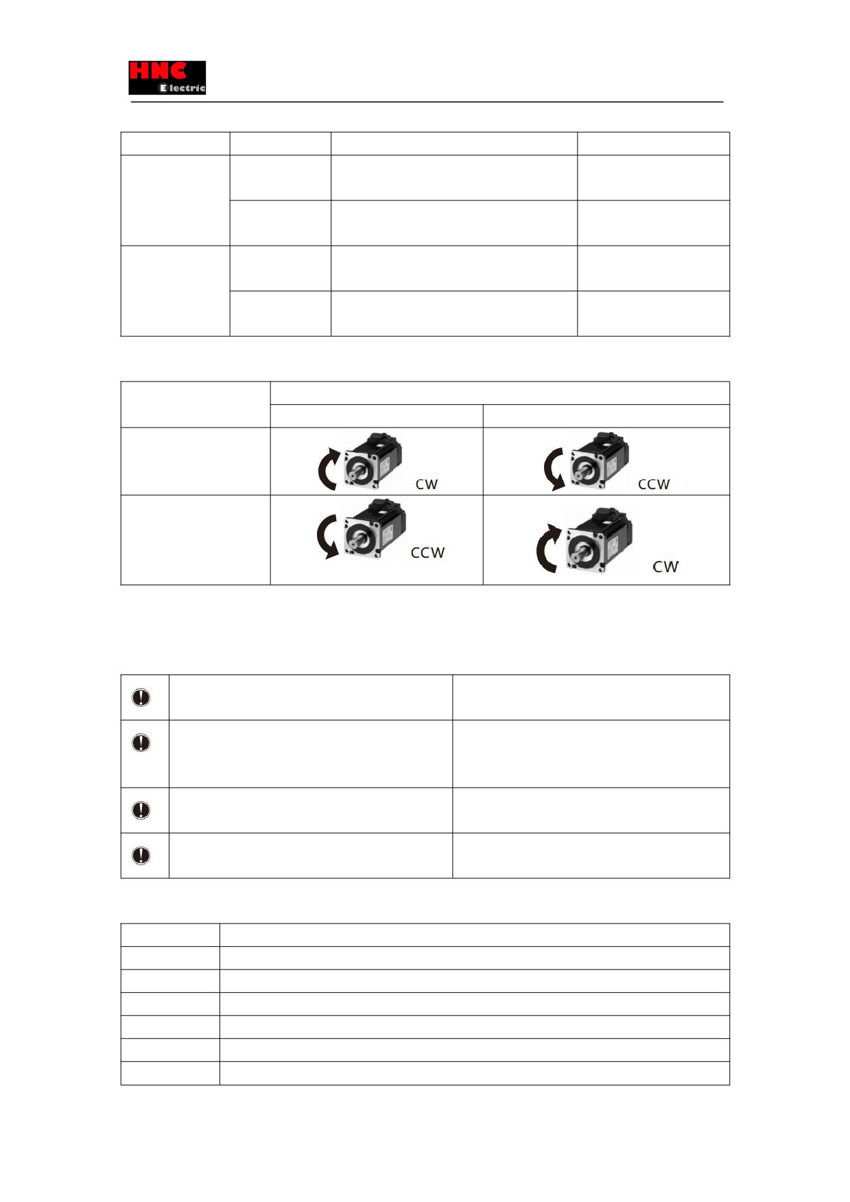
Table 8.3.5 Analog speed command Speed limit value settings
Rotation direction
Parameter No.
Parameter
Setting value
CCW
52.0
Analog speed command
“3000”
CCW speed limit value(Numerator)
53.0
Analog speed command
“5000”
CCW speed limit value(Denominator)
CW
54.0
Analog speed command
“3000”
CW speed limit value(Numerator)
55.0
Analog speed command
“5000”
CW speed limit value(Denominator)
Table 8.3.6 Parameter 62.0 settings and rotation direction of the motor (Analog speed command input)
Value of parameter 62.0
Input analog command
Positive voltage
Negative voltage
0
1
[Initial value]
8.3.3 Test run (Analog speed command input)
■Before test run
Table 8.3.7
Make sure all the wiring are connected properly before
To prevent electric shock, fire, malfunction and injury.
switch on the power to the drive and motor.
Test run after setting the basic parameters.
If set the wrong basic parameters, the motor will not
run, run unsteadily or lose control, which may cause
some injury or accidents.
Confirm the operation of the motor alone first before test
The unexpected movements, such as unstable action
run. (Remove the other connection to the mechanics.)
or lose control, may cause tome injury or accidents.
Drive the motor after release the brake on the motor if
If not, it may cause the malfunction to the brake and
the motor is attached with the brake.
motor.
■Test run
Table 8.3.8 Steps for test run (Analog speed command input)
Steps
Operation
1
Make sure all the wiring are connected properly.
2
Switch on the power to the drive.Note1)
3
Switch on the main circuit power to the drive(200V AC).
4
Connect SVON terminal of CN1 connector to COM- to make the servo ON.
5
Input the analog speed command voltage at a low voltage to make the motor run at a low speed.
6
Improve the position command pulse frequency gradually after confirming the safe implementation of
107
actual operation. Then confirm the operation until it comes to the specified speed.
Note1: The control power supply for the models of 750W or less are supplied by external 24V DC. 1kW or more are supplied
from internal. So the control power supply of models of 1kW or more can be ON or OFF by switching on or cutting off the main
circuit AC power.
8.4 Speed control mode (Internal speed command)
8.4.1 Wiring for user I/O connector(CN1) (Internal speed command)
Name
Symbol
Pin No.
Signal name
Contents
User I/O
CN1
1
24V
Drive control power supply 24V input
●24V power
2
G24V
Drive control power supply GND
supply input
3
COM+
I/O power supply 24V input
●Parallel I/O
4
SVON
Servo ON input
●Pulse command
5
RESET
Alarm reset input
input
6
VCRUN1
Input internal speed command-start 1(CCW ON)
●Analog input
7
VCRUN2
Input internal speed command-start 1(CW ON)
●ABZ output
8
VCSEL1
Input internal speed command-Speed command
selection 1
9
VCSEL2
Input internal speed command-Speed command
selection 2
10
VCSEL3
Input internal speed command-Speed command
selection 3
11
TLSEL1
Torque limit input
12
COM-
I/O power supply GND
13
MBRK
Brake release output
14
SERVO
Servo status output
15
-
Reserved
16
-
Reserved
17
T-LIMIT
Torque limit output
18
OCZ
Encoder Z-phase output (open collector)
19
SRDY+
Servo ready output +
20
SRDY-
Servo ready output -
21
ALM+
Servo alarm output+
22
ALM-
Servo alarm output-
23
NC1
Reserved (Disconnected)
24
-
Reserved
25
-
Reserved
26
-
Reserved
108
27
-
Reserved
28
-
Reserved
29
-
Reserved
30
-
Reserved
31
-
Reserved
32
-
Reserved
33
-
Reserved
34
-
Reserved
35
-
Reserved
36
OUT_A
Encoder A phase output
37
/OUT_A
Encoder /A phase output
38
OUT_B
Encoder B phase output
39
/OUT_B
Encoder /B phase output
40
OUT_Z
Encoder Z phase output
41
/OUT_Z
Encoder /Z phase output
42
SG
Signal ground
43
485
EIA-485 communication data
44
/485
EIA-485 communication /data
45
SG
Signal ground
46
NC2
Reserved(Disconnected)
47
-
Reserved
-
48
Reserved
49
-
Reserved
-
50
Reserved
109
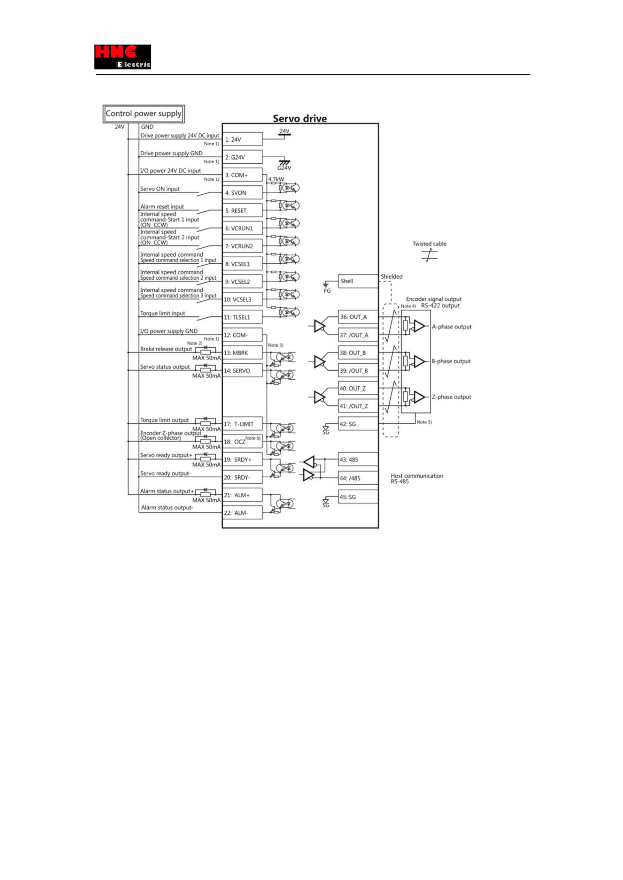
Note 1)Control power supply(24V, G24V) and I/O power (COM+, COM-) share the same power supply(For the models of
750W or less).
Note 2)If there is drive inductive load(relay), please use protective circuits(diode).
Note 3) Transistor output is an open collector output circuit of the Darlington-connected. It should be connected with relay or
optocoupler. Please don’t connect transistor directly because the voltage VCE(SAT) between collector and emitter is about
1V which cannot meet the required voltage VIL of TTL IC when transistor is ON.
Note 4) Terminal resistance must be connected as shown in the wiring diagram.
Note 5) Connect the signal ground on the host control device of output signal of the encoder. The connection of signal ground
and power supply GND may cause malfunction.
Note 6) If the pulse width of Z-phase is too narrow to identify the host control device, please reduce the encoder pulse output
division and multiplication No.276.0, 278.0 or reduce the speed to increase the pulse width.[Pulse width]=1/speed/(division
and multiplication×217)
8.4.2 Setting of basic parameters (Internal speed command)
110
Set the basic parameters.
The following parameters must be set if the drive needs to be driven by internal speed command.
Table 8.4.2 Parameters of control mode change (Internal speed command)
Parameter No.
Parameter
Description
2.0
Select control mode
Set to “1”.
3.0
Select command mode
Set to “3”.
388.0
Type of internal speed command
Set to “1”.
Table 8.4.3 Speed parameter of internal speed command
Parameter No.
Parameter
Description
390.0
Acceleration time (Note 1)
Initial value: 1000 [ms]
391.0
Deceleration time (Note 2)
Initial value: 1000 [ms]
392.0
Target speed 1
Initial value: 500 [r/mi n]
393.0
Target speed 2
Initial value: 1000 [r/mi n]
394.0
Target speed 3
Initial value: 1500 [r/mi n]
395.0
Target speed 4
Initial value: 2000 [r/mi n]
396.0
Target speed 5
Initial value: 2500 [r/mi n]
397.0
Target speed 6
Initial value: 3000 [r/mi n]
398.0
Target speed 7
Initial value: 4000 [r/mi n]
399.0
Target speed 8
Initial value: 5000 [r/mi n]
Note 1) Time for speed command from 0 [r /mi n] to 1000 [r /mi n].
Note 2) Time for speed command from 1000 [r /mi n] to 0 [r /mi n].
The speed setting parameter from [392.0] to [399.0] can be set in the specified
range, but some models cannot reach the speed shown on the setting pane. For
Points
the target speed setting, please refer to the specification of the motor.
8.4.3 Test run (Internal speed command)
■Before test run
Table 8.4.4
Make sure all the wiring are connected properly before
To prevent electric shock, fire, malfunction and injury.
switch on the power to the drive and motor.
Test run after setting the basic parameters.
If set the wrong basic parameters, the motor will not
run, run unsteadily or lose control, which may cause
some injury or accidents.
Confirm the operation of the motor alone first before test
The unexpected movements, such as unstable action
run. (Remove the other connection to the mechanics.)
or lose control, may cause tome injury or accidents.
Drive the motor after release the brake on the motor if
If not, it may cause the malfunction to the brake and
the motor is attached with the brake.
motor.
■Test run
Table 8.4.5 Steps for test run (Internal speed command)
Steps
Operation
1
Make sure all the wiring are connected properly.
2
Switch on the power to the drive.Note1)
111
3
Switch on the main circuit power to the drive(200V AC).
4
Make the SVON input of drive ON to start the motor excitation. (Connect the I 1 terminal to the COM-)
5
Select the target speed according to the ON/OFF combination of I 5(VCSEL1),I 6(VCSEL2)and I 7
(VCSEL3). When I 3(VCRUN1)or I 4(VCRUN2), it will rotate according to the setting direction.
ON: COM- short-circuit
OFF: COM- open-circuit
Note1: The control power supply for the models of 750W or less are supplied by external 24V DC. 1kW or more are supplied
from internal. So the control power supply of models of 1kW or more can be ON or OFF by switching on or cutting off the main
circuit AC power.
Table 8.4.6 Motor rotation direction of internal speed command
Motor rotation direction
Operation
(I 3)VCRUN1
(I
4)VCRUN2
CCW
ON
OFF
CW
OFF
ON
Motor stop
OFF
OFF
Motor stop
ON
ON
Table 8.4.7 Motor rotation of internal speed command
Target speed
Operation
I 5 (VCSEL1)
I 6 (VCSEL2)
I 7 (VCSEL3)
(CN1 8 pins)
(CN1 9 pins)
(CN1 10 pins)
1
OFF
OFF
OFF
2
ON
OFF
OFF
3
OFF
ON
OFF
4
ON
ON
OFF
5
OFF
OFF
ON
6
ON
OFF
ON
7
OFF
ON
ON
8
ON
ON
ON
8.5 Torque control mode (Analog torque command input)
8.5.1 Wiring for user I/O connector (CN1)(Analog torque command input)
Table 8.5.1
Name
Symbol
Pin No.
Signal name
Contents
User I/O
CN1
1
24V
Drive control power supply 24V input
●24V power
2
G24V
Drive control power supply GND
supply input
3
COM+/-
I/O power supply 24V input
●Parallel I/O
4
SVON
Servo ON input
●Pulse command
5
RESET
Alarm reset input
112
input
6
HOLD
Command input restriction(Zero speed clamp)
●Analog input
7
-
Reserved
●ABZ output
8
-
Reserved
9
CCWL
CCW drive input restriction
10
CWL
CW drive input restriction
11
TLSEL1
Torque limit input
12
COM-
I/O power supply GND
13
MBRK
Brake release output
14
SERVO
Servo status output
15
-
Reserved
16
-
Reserved
17
T-LIMIT
Torque limit output
18
OCZ
Encoder Z-phase output (open collector)
19
SRDY+
Servo ready output +
20
SRDY-
Servo ready output -
21
ALM+
Servo alarm output+
22
ALM-
Servo alarm output-
23
NC1
Reserved (Disconnected)
24
-
Reserved
25
-
Reserved
26
-
Reserved
27
-
Reserved
28
-
Reserved
29
-
Reserved
30
-
Reserved
31
-
Reserved
32
A_TRQ
Analog torque command input
33
A_GND
Analog speed command input ground
34
-
Reserved
35
-
Reserved
36
OUT_A
Encoder A phase output
37
/OUT_A
Encoder /A phase output
38
OUT_B
Encoder B phase output
39
/OUT_B
Encoder /B phase output
40
OUT_Z
Encoder Z phase output
41
/OUT_Z
Encoder /Z phase output
42
SG
Signal ground
113
43
485
EIA-485 communication data
44
/485
EIA-485 communication /data
45
SG
Signal ground
46
NC2
Reserved(Disconnected)
47
-
Reserved
-
48
Reserved
-
49
Reserved
-
50
Reserved
Note 1)Control power supply(24V, G24V) and I/O power (COM+, COM-) share the same power supply(For the models of
750W or less).
Note 2)If there is drive inductive load(relay), please use protective circuits(diode).
Note 3) Transistor output is an open collector output circuit of the Darlington-connected. It should be connected with relay or
114
optocoupler. Please don’t connect transistor directly because the voltage VCE(SAT) between collector and emitter is about
1V which cannot meet the required voltage VIL of TTL IC when transistor is ON.
Note 4) Terminal resistance must be connected as shown in the wiring diagram.
Note 5) Terminal resistance must be connected as shown in the wiring diagram.
Note 6) Connect the signal ground on the host control device of output signal of the encoder. The connection of signal ground
and power supply GND may cause malfunction.
Note 7) If the pulse width of Z-phase is too narrow to identify the host control device, please reduce the encoder pulse output
division and multiplication No.276.0, 278.0 or reduce the speed to increase the pulse width.[Pulse width]=1/speed/(division
and multiplication×217)
8.5.2 Setting of basic parameter (Analog torque command input)
Set the basic parameters.
The following parameters must be set if the drive needs to be driven by analog torque command input.
Table 8.5.2 Parameters of control mode change (Analog torque command input)
Parameter No.
Parameter
Description
2.0
Select control mode
Set to “2”.
3.0
Select command mode
Set to “2”.
The user can select the parameter [152.0], [288.0] to [302.0] in the following table according to the actual usage.
For details, refer to 「Chapter 6 Parameter」.
Table 8.5.3 Parameters of analog torque command input
Parameter No.
Parameter
Description
152.0
Analog torque command Speed limit [rpm]
Set the speed limit value.
288.0
Analog torque command input filter (Numerator)
Filter out the input command voltage
289.0
Analog torque command input filter (Denominator)
interference. Use it with parameter 302.1.
290.0
Analog torque command input gain (Numerator)
Set the torque at the maximum command
291.0
Analog torque command input gain
(Denominator)
input voltage (±10V). (Note 1)
292.0
Analog torque command CCW torque limit Override
Set torque limit value at CCW rotation.(Note
(Numerator)
2)
293.0
Analog torque command CCW torque limit
Override(Denominator)
294.0
Analog torque command CW torque limit Override
Set torque limit value at CW rotation.(Note
(Numerator)
2)
295.0
Analog torque command CW torque limit
Override(Denominator)
300.0
Analog speed command
- Fixed offset value
The motor speed is 0[ 0.1%] by adjusting the
command input to 0V. Use it with parameter
302.2..
302.0
Analog speed command
- Rotational direction
For details, refer to table 5.5.6.
302.1
Analog speed command
- Selection of input filter
Please use it with parameter 288.0, 289.0.
302.2
Analog speed command
- Selection of offset tuning
Please use it with parameter 300.0.
method
Note 1: Set the maximum torque for the motor in parameter 289.0(Denominator). Set the expected maximum torque in
parameter 288.0(Numerator).
115
Example) Make the following settings if the motor with the maximum torque of 3000 [0.1%] needs to set to 1000 [0.1%] at the
maximum command input voltage (±10V).
Table 8.5.4 Analog torque command input filter settings
Parameter No.
Parameter
Setting value
288.0
Analog torque command Input filter constant (Numerator)
“1000”
289.0
Analog torque command Input filter constant (Denominator)
“3000”
Note 2: Set the maximum torque for the motor in parameter 293.0, 295.0(Denominator). Set the expected torque limit value in
parameter 292.0, 294.0(Numerator).
Example) Make the following settings if the motor with the maximum torque of 3000 [0.1%] needs to set to the maximum
speed limit value of 1000 [0.1%].
Table 8.5.5 Analog torque command input Torque limit value settings
Rotation direction
Parameter No.
Parameter
Setting value
CCW
292.0
Analog torque command
“1000”
CCW torque limit value(Numerator)
293.0
Analog torque command
“3000”
CCW torque limit value (Denominator)
CW
294.0
Analog torque command
“1000”
CW torque limit value (Numerator)
295.0
Analog torque command
“3000”
CW torque limit value (Denominator)
Table 8.5.6 Parameter 302.0 settings and rotation direction of the motor (Analog torque command input)
Value of parameter 62.0
Input analog command
Positive voltage
Negative voltage
0
1
[Initial value]
8.5.3 Test run (Analog torque command input)
■Before test run
Table 8.5.7
Make sure all the wiring are connected properly before
To prevent electric shock, fire, malfunction and injury.
switch on the power to the drive and motor.
Test run after setting the basic parameters.
If set the wrong basic parameters, the motor will not
run, run unsteadily or lose control, which may cause
some injury or accidents.
Confirm the operation of the motor alone first before test
The unexpected movements, such as unstable action
run. (Remove the other connection to the mechanics.)
or lose control, may cause some injury or accidents.
116
Drive the motor after release the brake on the motor if
If not, it may cause the malfunction to the brake and
the motor is attached with the brake.
motor.
■Test run
Table 8.5.8 Steps for test run (Analog torque command input)
Steps
Operation
1
Make sure all the wiring are connected properly.
2
Switch on the power to the drive.Note1)
3
Switch on the main circuit power to the drive(200V AC).
4
Set a smaller value about 500 in parameter 152.0(speed limit value) to limit the speed.
5
Make the SVON input of drive ON to start the motor excitation. (Connect the I 1 terminal to the COM-)
6
Input the analog torque command voltage at a low voltage to make the motor run at a low speed.
7
Improve the analog torque command voltage gradually after confirming the safe implementation of actual
operation. Set the actual value in parameter 152.0(speed limit value).
Note1: The control power supply for the models of 750W or less are supplied by external 24V DC. 1kW or more are supplied
from internal. So the control power supply of models of 1kW or more can be ON or OFF by switching on or cutting off the main
circuit AC power.
8.6 Position control mode(Internal position command)
Set the following parameter of control mode selection and command mode selection to come into the internal position
command mode. Use the locator to test run.
Table 8.6.1 Parameter of control mode change(Internal position command)
Parameter No.
Parameter
Description
2.0
Select control mode
Set to “0”.
3.0
Select command mode
Set to “3”.
8.6.1 Locator function
Execute the positioning according to the I/O command from the host control device, such as PLC.
8.6.2 Test run
Send the command from PC according to the steps, not the command from host control device(such as PLC), and have the
test run, such as back and forth movement.
8.6.3 Precautions
1) Alarm code No.10 「Position command overflow/ Home position reset failure」will happen in the following two conditions.
1. Out of the range of -1, 073, 741, 823~+1, 073, 741, 823 「Command unit」
2. 「Internal position command - Overflow detection option」(Parameter No.643.0) is set to “1=Enable”
Considering the above factors, please set 「Internal position command - Overflow detection option」(Parameter No.643.0)
according to the following table.
Table 8.6.2 Parameter setting of internal position command mode
Operation method(Function)
Internal position command - Overflow detection option
Command
(Parameter No.643.0)
Positioning function
Absolute value
0=DisableNote1)
1=Enable
Relative value
0=Disable
Test run
117
Note 1) The home position in the drive may disappear sometimes. Please reset the home position after parameter setting.
2) Please set 「Selection of Auto interpolation for command division and multiplication」(Parameter No.32.2) to “1=Enable”.
Initial value is “1=Enable”. When “0=Disable” is set, the speed change will become large.
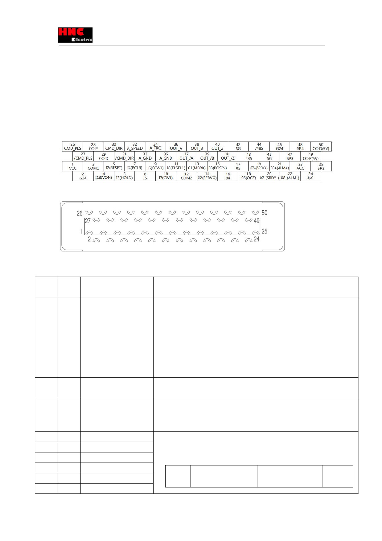
8.7 Description of User I/O connector (CN1) terminal arrangements
Figure 8.7.1 Terminal arrangements
Figure 8.7.2 Connector
8.7.1 Signal description
Signal
Pin
Contents
Function
name
No.
24V
1
Drive control power supply
●Connect with +24V of 24VDC external power supply
24V input
●The power supply voltage is 24VDC±10%、100mA(Typ.)
●24VDC external power supply should meet the following condition:
Using SELV power supply(※).
※SELV: safety extra low voltage
(Reinforced insulation is needed for safety extra low voltage, non-dangerous voltage and
dangerous voltage.)
G24V
2
Drive control power supply
●Connect to GND of 24VDC external power supply
GND
COM+
3
I/O power supply 24V input
●Connect the common terminal of 24VDC power supply used for I/O and optical coupler
circuit used
●Power voltage: 24VDC±10%、100mA(Typ.)
I1
4
I1 input
●Parallel I/O input
I2
5
I2 input
●The function varies according to the different control mode/ command mode. For details,
I3
6
I3 input
refer to
「Table 5.7.2 I/O input signal 」
I4
7
I4 input
Control
Position control
Speed control
Torque
I5
8
I5 input
mode
control
I6
9
I6 input
118
I7
10
I7 input
Comma
Pulse train
Internal
Analog
Internal
Analog
I8
11
I8 input
nd
command
regeneration
command
regeneration
command
mode
command
command
I1
SVON
I2
RESET
RESET/PCLR
RESET
RESET
RESET
I3
HOLD
PCSTART1
HOLD
VCRUIN1
HOLD
I4
PCLR
PCSEL1
(Reserved)
VCRUIN2
(Reserved)
I5
(Reserved)
PCSEL2
(Reserved)
VCS L1
(Reserved)
I6
CCW
PC EL3
CCWL
VCSEL2
CCWL
I7
CWL
PCSEL4
CWL
VCSEL3
CWL
I8
TLSEL1
ORG
TLSEL1
TLSEL1
TLSEL1
COM-
12
I/O power supply GND
●Connected with GND of 24VDC power supply used for I/O
CMD_
26
[Differential input]
[Differential input] Max. command pulse frequency 4Mpps
PLS
①Pulse + direction pulse
①Input pulse + direction pulse from host control device (differential input)
②Orthogonal phase
②Input A phase of AB phase orthogonal difference pulse signal from host control device
difference pulse-A
(differential input)
③CCW+CW Pulse CCW
③Input CCW+CCW of CW pulse from host control device (differential input)
[5V open collector circuit]
[5V open collector circuit] Max. command pulse frequency 200kpps
④5V power supply of input
④5V power supply input terminal of /CMD_ PLS
/CMD PLS
/CMD_
27
[Differential input]
[Differential input] Max. command pulse frequency 4Mpps
PLS
①Pulse + direction/ pulse
①Input pulse + direction/ pulse from host control device (differential input)
②Orthogonal phase
②Input /A phase of AB phase orthogonal difference pulse signal from host control device
difference pulse /A phase
(differential input)
③CCW+CW Pulse /CCW
③Input CCW +/CCW of CW from upper control device (differential input)
[5v/24v open collector circuit]
[5V open collector circuit] Max. command pulse frequency 200kpps
④Pulse + direction pulse
④Input pulse + pulse of direction from host control device
⑤Orthogonal phase
⑤Input A phase of AB phase orthogonal difference pulse signal from host control device
difference pulse /A phase
⑥Input CCW +CCW of CW pulse from host control device
⑥CCW+CW pulse CCW
CC-P
28
[24V open collector circuit
[24V open collector circuit] Max. command pulse frequency
200kpps
input]
①24V power supply input terminal of /CMD_PLS
①24V of /CMD_PLS
CC-D
29
[24V open collector circuit
[24V open collector circuit] Max. command pulse frequency
200kpps
input]
①24V power supply input terminal of /CMD_DIR
①24V of /CMD_DIR
CMD_
30
[Differential input]
【Differential input】Max. command pulse frequency
4Mpps
DIR
①Pulse + direction direction
①Input pulse + direction direction from host control device(differential input)
119