SERVO DRIVE SV-E3 SERIES. INSTRUCTION MANUAL (v1.5) - page 5
Target speed 8
4
Short circuited
Short circuited
Open
5
Open
Open
Short circuited
6
Short circuited
Open
Short circuited
7
Open
Short circuited
Short circuited
8
Short circuited
Short circuited
Short circuited
[Initial value]
Target speed 1: 500
[r/min]
Target speed 2: 1000 [r/min]
Target speed 3: 1500 [r/min]
Target speed 4: 2000
[r/min]
Target speed 5: 2500
[r/min]
Target speed 6: 3000
[r/min]
Target speed 7: 4000(200W~750W motor)[r/min]
3000(1KW~2KW motor)[r/min]
Target speed 8: 5000(200W~400W motor)[r/min]
4500(750W motor)[r/min]
3000(1KW~2KW motor)[r/min]
[Setting range] 0 to the highest speed of motor
642. 0
[Basic setting]
Set Operation mode for position control mode and internal generation command.
No
Internal speed
0 = Point Table
command -
1 = Communication operation
Operation mode
2 = Manual pulse input
[Initial value] 1 (Communication operation)
[Setting range] 0 to 2
643. 0
[Special setting]
Enable/Disable Internal position command Overflow detection function.
Yes
Internal speed
0 = Disable
command -
1 = Enable
Overflow detection
To prevent the absolute position from disappearing when the target position exceeds
option
the absolute position range in Point table or communication operation.
When “1 = Enable” is set and the target position (ABS position command) in operation
command exceeds absolute position, the alarm of internal position command overflow
will occur. When “0 = Disable” is set and the target position
exceeds absolute
position, it can implement relative operation, not the absolute operation. The relative
operation is that the point table operation command method is set to the operation of
relative value and test-run. The absolute operation is that the point table operation
command method is set to the operation of absolute value.
[Initial value] 1
[Setting range] 0 to 1
644. 0
[Special setting]
Set Point No. output method from user I/O output to PM1...3 in positioning operation.
No
Point No. output
0 = Output Operation start point at Operation start
method
1 = Output Operation start point at Operation end
2 = Output each point No.at each operation start
[Initial value] 1 (Output Operation start point at Operation end)
[Setting range] 0 to 2
80

645. 0
[Special setting]
Select Base signal 1 at determine Home position.
No
Base signal 1
0 = Arbitrary position
selection for Home
1 = Stopper
position
2 = Home position DOG front end
[Initial value] 2 (Home position DOG front end)
[Setting range] 0 to 2
645. 1
[Special setting]
Set another base signal(Base signal 2)for home position after detecting Base signal 1.
No
Base signal 2
0 = None
selection for Home
1 = Encoder Phase Z
position
[Initial value] 0 (None)
[Setting range] 0 to 1
645. 3
[Special setting]
Set the Base signal 1 redetection in creep speed after detecting home position DOG
No
Home position
front end.
Base signal 1
0 = Disable
redetection
1 = Enable
[Initial value] 0 (None)
[Setting range] 0 to 1
646. 0
[Special setting]
Set Home position return direction.
No
Home position
0 = CCW direction
return direction
1 = CW direction
[Initial value] 0 (CCW direction)
[Setting range] 0 to 1
646. 1
[Basic setting]
Set Home position sensor input polarity.
No
Home position
0 = When OFF, detect Home position DOG front end
sensor input
1 = When ON, detect Home position DOG front end
polarity
[Initial value] 0 (When OFF, detect Home position DOG front end)
[Setting range] 0 to 1
646. 2
[Basic setting]
Enable/Disable Home position return Timeout.
No
Home positon
0 = Disable
return Timeout
1 = Enable
option
[Initial value] 1 (Enable)
[Setting range] 0 to 1
646.3
[Basic setting]
Select a function for Point No.0 when PCSTART1 is put into user I/O in forward start.
No
Point No.0
0 = Return to home position
function selection
1 = Point table operation
[Initial value] 0 (Return to home position)
[Setting range] 0 to 1
647. 0
[Basic setting]
Select whether to switch the torque limit value of home position return to home position
No
Home position
return limit value.
return Torque limit
0 = Disable
option
1 = Enable
The torque limit detected by stopper is irrelative to the setting of this parameter in
using home position return of stopper.
81
[Initial value] 0 (Disable)
[Setting range] 0 to 1
647. 1
[Basic setting]
Select “ 1= Move” from home position base signal 1 detection to home position
No
Action at home
completion.
position return
0 = No move
completion
1 = Move
[Initial value] 0 (No move)
[Setting range] 0 to 1
648. 0
[Basic setting]
Set the speed after the home position base signal 1 is detected.
No
Home position
[Initial value] 500[rpm]
return Speed
[Setting range] 1 to Max. speed of motor
649. 0
[Basic setting]
Set the creep speed after the home position base signal 1 is detected.
No
Home position
[Initial value] 10[rpm]
return Creep
[Setting range] 1 to Max. speed of motor
speed
650. 0
[Basic setting]
Set Acceleration/Deceleration time for Home position return
No
Home position
This parameter sets Acceleration time and Deceleration time per 1000rpm.
return
If the load inertia ratio is 10 times or more, set up a value more than the initial value of
Acceleration/Dece
30. Otherwise, vibration will occur.
leration time
[Initial value] 30[ms/1000rpm]
[Setting range] 0~to 5000
651. 0
[Special setting]
Set shift quantity from the position where the Base signal was detected to the home
No
Home position
position.
Return
[Initial value]
0 [Command unit]
Shift-to-home-posi
[Setting range] 0 to 1,000,000,000
tion quantity
653. 0
[Special setting]
Set a position at the time of home position return complete.
No
Home position
[Initial value]
0 [Command unit]
return Home
[Setting range]
-1,000,000,000 to 1,000,000,000
position data
655. 0
[Special setting]
Set Torque limit detection at the time of press home position return.
No
Home position
[Initial value]
100 [ms]
return Press
[Setting range] 5 to 1,000
detection time
656. 0
[Special setting]
Set Torque limit value at the time of home position return. This value is measured in
No
Home position
terms of proportion to rated torque. This setting value is the torque limit value of press
return Torque limit
home position return.
value
[Initial value] 500[0.1%]
[Setting range] 10 to 3,000
657. 0
[Special setting]
Set a distance from the positon where Base signal 1 for home position is detected to
No
Home position
the position where Phase Z detection starts.
return Phase Z
[Initial value] 0 [Command unit]
invalidation
[Setting range] 0 to 1,000,000,000
distance
82
659. 0
[Special setting]
Set Home position return Timeout Time.
No
Home position
[Initial value] 60,000[10ms]
return Timeout
[Setting range] 0 to 60,000
Time
6.2 Parameter list for point table
Table 6.2.1 Parameter list for point table
Point
Position
Rotation
Acceleration
Deceleration
Command
Dwell time
Running
Positioning
valid/ Invalid
No.
[Command
speed
time [ms]
time [ms]
method [-]
[ms]
operation [-]
completion
[-]
pulse]
[r/min]
[Encoder
pulse]
0
No.722.0
No.724.0
No.726.0
No.727.0
No.720.0
No.728.0
No.720.1
No.729.0
No.720.3
1
No.742.0
No.744.0
No.746.0
No.747.0
No.740.0
No.748.0
No.740.1
No.749.0
No.740.3
2
No.762.0
No.764.0
No.766.0
No.767.0
No.760.0
No.768.0
No.760.1
No.769.0
No.760.3
3
No.782.0
No.784.0
No.786.0
No.787.0
No.780.0
No.788.0
No.780.1
No.789.0
No.780.3
4
No.802.0
No.804.0
No.806.0
No.807.0
No.800.0
No.808.0
No.800.1
No.809.0
No.800.3
5
No.822.0
No.824.0
No.826.0
No.827.0
No.820.0
No.828.0
No.820.1
No.829.0
No.820.3
6
No.842.0
No.844.0
No.846.0
No.847.0
No.840.0
No.848.0
No.840.1
No.849.0
No.840.3
7
No.862.0
No.864.0
No.866.0
No.867.0
No.860.0
No.868.0
No.860.1
No.869.0
No.860.3
8
No.882.0
No.884.0
No.886.0
No.887.0
No.880.0
No.888.0
No.880.1
No.889.0
No.880.3
9
No.902.0
No.904.0
No.906.0
No.907.0
No.900.0
No.908.0
No.900.1
No.909.0
No.900.3
10
No.922.0
No.924.0
No.926.0
No.927.0
No.920.0
No.928.0
No.920.1
No.929.0
No.920.3
11
No.942.0
No.944.0
No.946.0
No.947.0
No.940.0
No.948.0
No.940.1
No.949.0
No.940.3
12
No.962.0
No.964.0
No.966.0
No.967.0
No.960.0
No.968.0
No.960.1
No.969.0
No.960.3
13
No.982.0
No.984.0
No.986.0
No.987.0
No.980.0
No.988.0
No.980.1
No.989.0
No.980.3
14
No.1002.0
No.1004.0
No.1006.0
No.1007.0
No.1000.0
No.1008.0
No.1000.1
No.1009.0
No.1000.3
15
No.1022.0
No.1024.0
No.1026.0
No.1027.0
No.1020.0
No.1028.0
No.1020.1
No.1029.0
No.1020.3
7. Timing chart
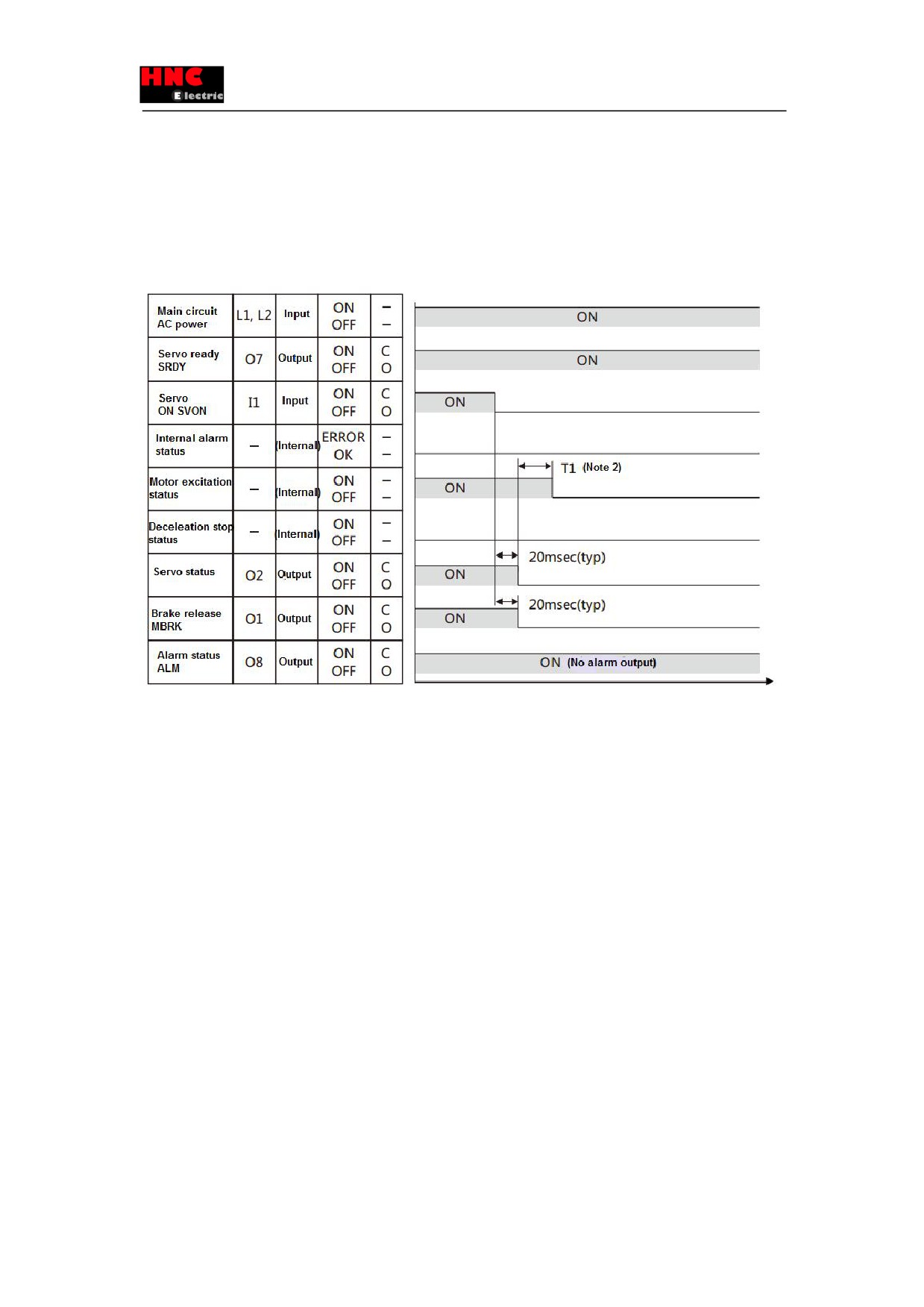
7.1 Power ON
Figure 7.1.1 Power ON
83
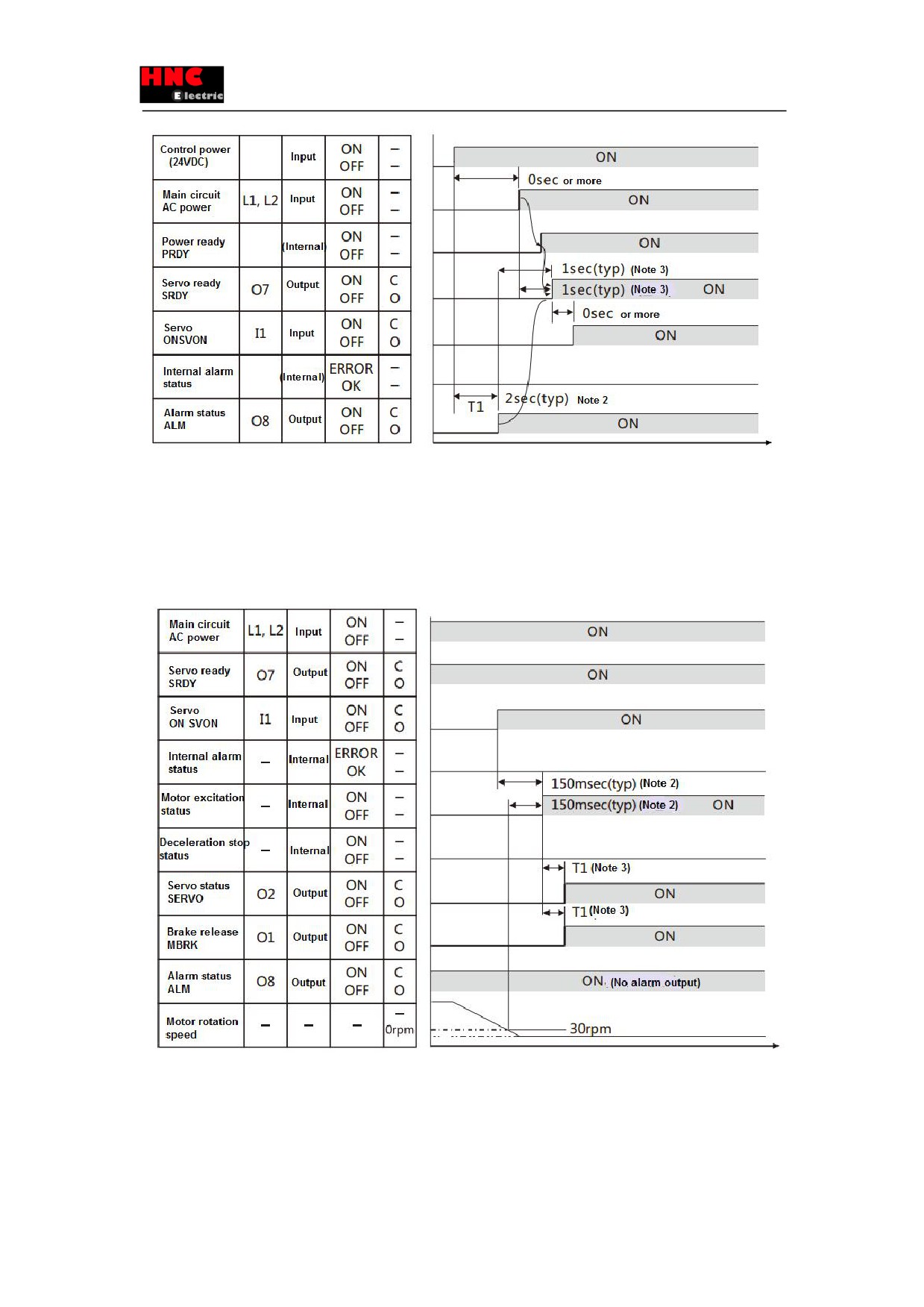
Note 1) About I/O status, “C” indicates the internal output circuit contact or external contact is close, while “O” means open.
Note 2) After the parameters are cleared, 5sec is needed for T1 because of parameter initialization.
Note 3) When /ERROR and main circuit power supply PRDY is ON, S-RDY is ON.
7.2 Servo OFF→ON
Note 1) About I/O status, “C” indicates the internal output circuit contact or external contact is close, while “O” means open.
Note 2) The servo can be not ON when motor speed is less than 30rpm..
Note 3) T1 can be set in parameter No.238.0. (Initial value 4msec, value range: 0 to 500msec)
84
7.3 Servo stop
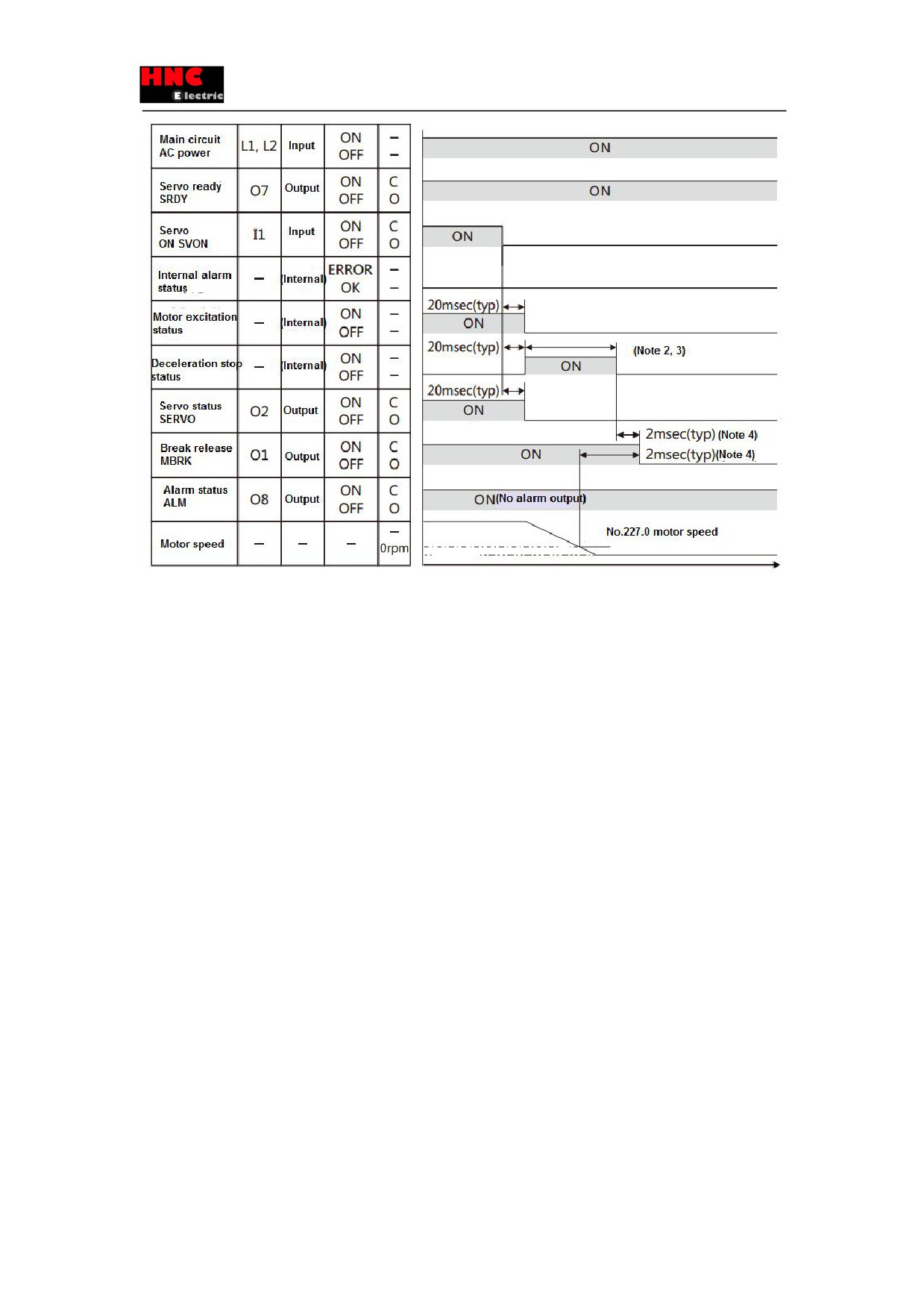
7. 3. 1 Servo ON→OFF(motor stops)
When servo OFF, the deceleration stop release condition is to reach the speed release, or after specified running
time(Parameter No.224.0=1, initial setting) , the motor speed is below the servo OFF deceleration stop release speed
(Parameter No.227.0=50rpm, initial setting).
Figure 7.3.1 Servo ON→OFF (motor stops)
Note 1) About I/O status, “C” indicates the internal output circuit contact and external contact is close, while
“O” means open.
Note 2) T1 can be set in parameter No.237.0 (initial setting 0msec, changeable range: 0 to 500msec).
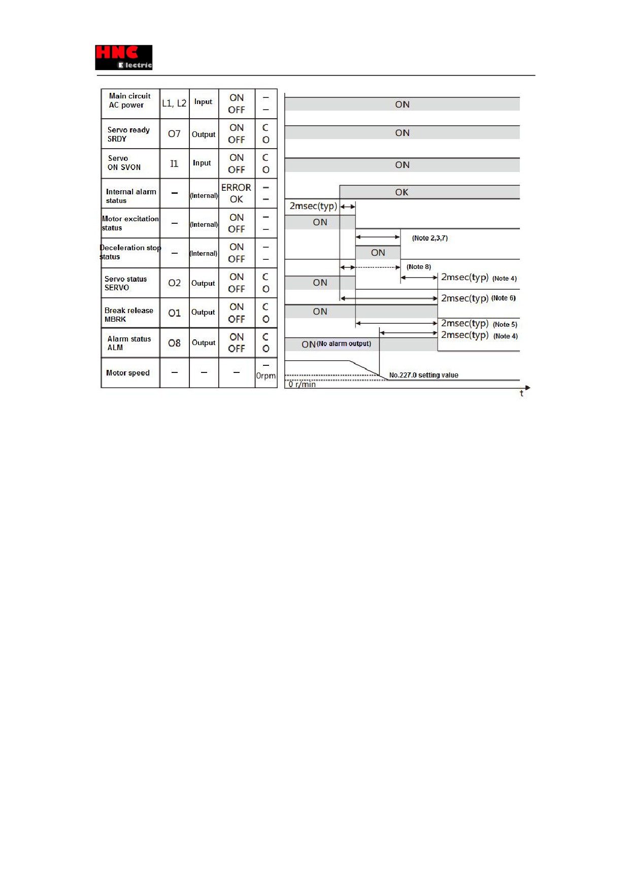
7.3.2 Servo ON →OFF(motor rotates)
When servo OFF, the deceleration stop release condition is to reach the speed release, or after specified running time
(Parameter No.224.0=1, preferences) but motor speed is above the servo OFF deceleration stop release speed r (Parameter
No.227.0=50rpm, preferences).
Figure 7.3.2 Servo ON →OFF(motor rotates)
85
Note 1) About I/O status, “C” indicates the internal output circuit contact and external contact is close, while
“O” means open.
Note 2) When servo OFF, it stops in the selected deceleration stop mode(Parameter No.224.0)..
Note 3) Immediate stop and short-circuit brake will finish when it meets the conditions of deceleration stop at servo OFF
(ParameterNo.224.1, 226.0, 227.0)
Note 4) MBRK will be OFF when the deceleration stop has completed or the motor speed is to reach the setting value
specified in parameter No.227.0. If deceleration stop mode is selected to the free-run (parameter No.224.0) at servo OFF, the
MBRK will be OFF when motor excitation is OFF.
7.4 At occurrence of alarm
Figure 7.4.1 At occurrence of alarm
86
Note 1) About I/O status, “C” indicates the internal output circuit contact and external contact is close, while
“O” means open.
Note 2) At servo OFF, via type selection, the deceleration stop (parameter No.224.0) will be:.
a) Prompt stop or short brake via short brake deceleration stop
b) Free run, free run stop
Note 3) Deceleration stop will finish when it meets the conditions of deceleration stop at servo OFF (parameter No.224.1,
226.0, 227.0) .
Note 4) MBRK will be OFF when the deceleration stop has completed or the motor speed is below the setting value specified
in parameter No.227.0. (excluding the occurrence of the alarm in Note 6)
Note 5) The MBRK will be OFF when motor excitation is OFF, when the free run is selected in No.224.0.
Note 6) When the following alarms occur, MBRK will be OFF right after internal alarm state is ERROR ..
a) Encoder error
b) Undervoltage of control power supply
c) Inverter output error
Note 7) When the following alarms occur, the deceleration stop will be in the following ways.
a) If motor speed cannot be detected due to encoder error. It will be OFF at the operation time in No.226.0.
b) Selection of deceleration stop at the power supply voltage(No.224.2) drops. When selecting 0(=Disable), free-run
stops. When selecting 1(=Enable), it will be OFF after the operation time (No.228.0) of power supply drop deceleration stop.
As the CPU will stop immediately, the actual operation time will be shortened.
c) Free-run stops as the inverter output error( inverter error 1, overvoltage error, overcurrent error, base circuit break)..
Note 8) When the following alarms occur, SERVO signal can be delayed to deceleration stop OFF.
a) Encoder error
b) Undervoltage of control power supply
87
7.5 Alarm reset
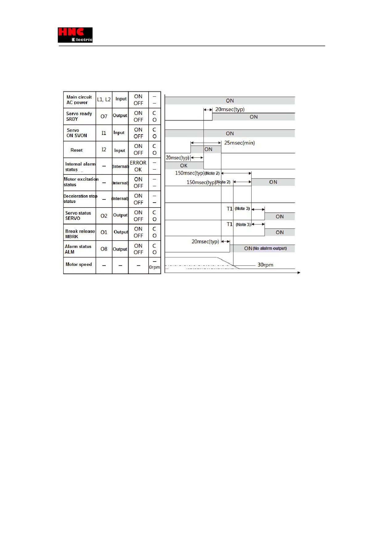
7.5.1 Alarm reset (SVON=ON)
Figure 7.5.1 Alarm reset (SVON=ON)
Note 1) About I/O status, “C” indicates the internal output circuit contact and external contact is close, while
“O” means open.
Note 2) The servo can be not ON when motor speed is less than 30rpm.
Note 3) T1 can be set in parameter No.238.0.(Initial value 4msec, value range: 0 to 500msec)
7.5.2 Alarm reset (SVON=OFF)
Figure 7.5.2 Alarm reset (SVON=OFF)
88
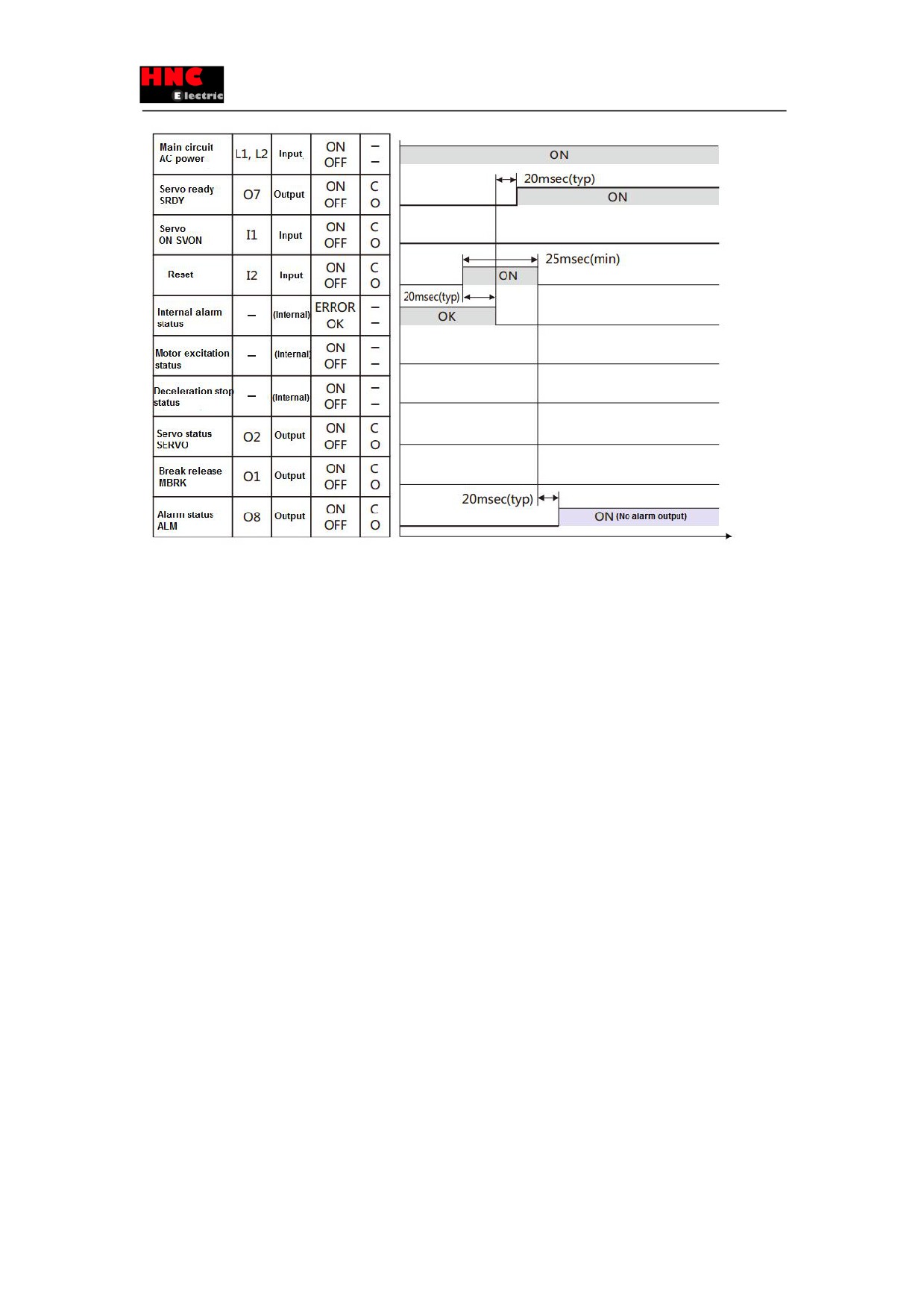
Note 1) About I/O status, “C” indicates the internal output circuit contact and external contact is close, while
“O” means open.
8. Operation
8.1 Preface
8.1.1 Preface
This product can drive the motor by 5 operation modes of combination of control mode and command mode.
This chapter describes the operation method of different operation modes.
■ Position control mode (Pulse position command input)
1) Wiring for user I/O (CN1) connector
The following three kinds of signals can be input in position control mode.
- Differential input
- 24V open collector input
- 5V open collector input
2) The setting of basic parameter
3) Test run
■ Speed control mode(Analog speed command input)
1) Wiring for user I/O (CN1) connector
2) The setting of basic parameter
3) Test run
■ Speed control mode(Internal speed command)
1) Wiring for user I/O (CN1) connector
2) The setting of basic parameter
3) Test run
89
■ Torque control mode (Analog torque command input)
1) Wiring for user I/O (CN1) connector
2) The setting of basic parameter
3) Test run
■ Position control mode (Internal position command)
8.1.2 Precautions
Table 8.1.1 Precautions
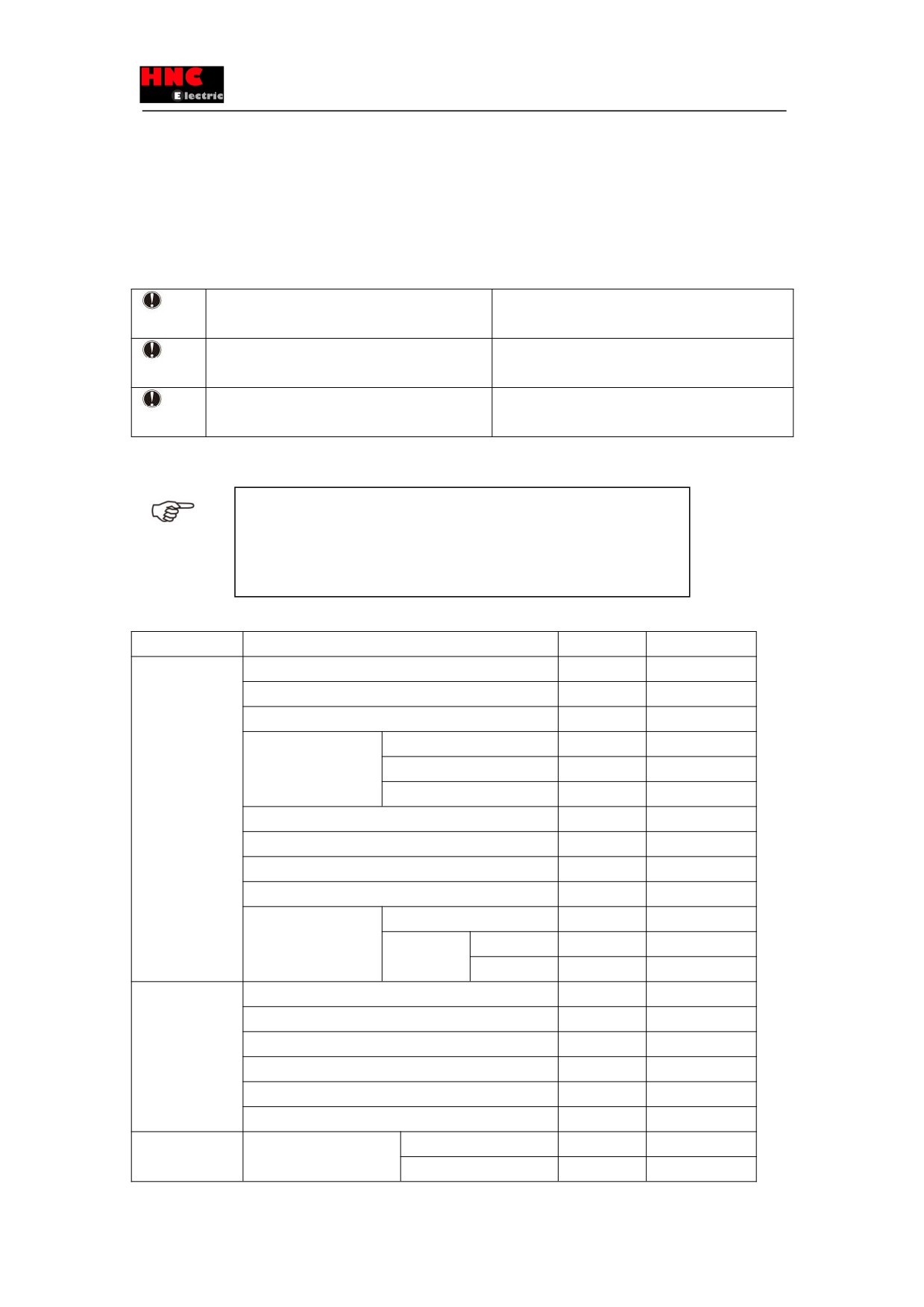
Make sure to cut off all phases of power supply
To .prevent electric shock, fire, malfunction and injury
before wiring.
The wiring should be performed by the professional
To .prevent electric shock, fire, malfunction and injury
electrical engineer.
Make sure all the wiring should be connected
To .prevent electric shock, fire, malfunction and injury
properly before power ON.
8.1.3 Common parameters
The common parameters in the following table should be set in all the operation
modes.
Point
Set the following parameters according to the using status.
For details, refer to [Chapter 6 Parameter list].
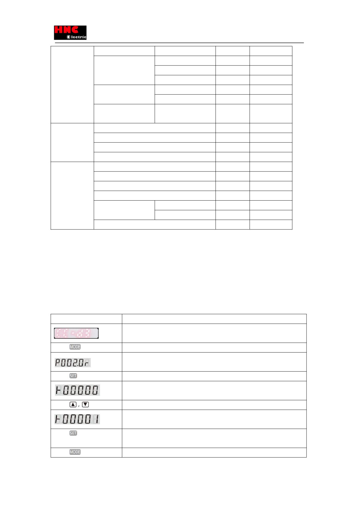
Table 8.1.2 Common parameter list
Types
Names
No.
Reference
Common
Control mode
2.0
parameters
Command mode
3.0
Operation mode
9.0
Torque command
Switch
144.0
range
Value 1
147. 0
Value 2
148. 0
Torque limit output
144.1
Delay time for servo OFF
237. 0
Delay time for mechanical brake release
238. 0
Absolute system
257. 0
Encoder pulse output
Rotation direction
257.0
Division and
Numerator
276. 0
multiplication
Denominator
278. 0
RS-485
Switch
8. 0
communication
Address
4. 0
Communication speed rate
6. 0
Stop bit
6. 1
Parity
6. 2
Minimum response time
11. 0
Fault detection
Position deviation
Switch
65. 0
Value
87.0
90
Delay time
89. 0
Speed deviation
Switch
65. 1
Value
90. 0
Delay time
91. 0
Encoder pulse output
Frequency upper limit
285. 0
Delay time
286. 0
Instantaneous
Delay time
305. 0
voltage-drop
Drive restriction
Setting
67. 0
options
Deceleration method
67. 1
Stop status
67. 2
Keep position deviation counter
67. 3
Deceleration stop
Method
224. 0
Release condition
224. 1
Operation time
226. 0
Rotation cancellation
227. 0
Control power supply error
Switch
224. 2
Operation time
228. 0
Torque command range
151. 0
8.1.4 Setting method for basic parameter
To drive the motor in the different operation modes, the setting and operation of the related basic parameter should be done
necessarily. Here are the steps of parameter setting and change by using ‘setting panel’.
■By setting panel
1. Switch on the power supply to the drive
2. Set the basic parameter according to the following steps.
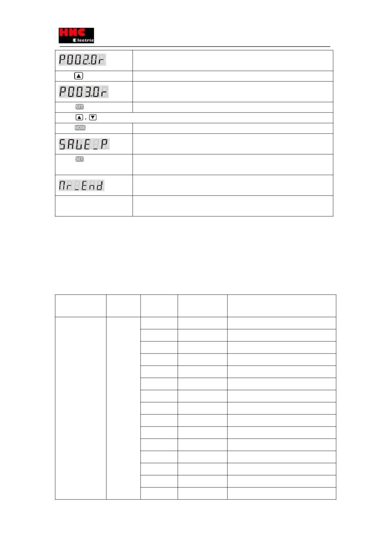
Table 8.1.3 Change of the basic parameter (By setting panel)
Display and operation
Description
Initial display at the start.
Press
button four times
Switch to the mode of setting panel.
Switch to the parameter mode. You can change the parameter No. here. (Display
parameter 2.0)
Press
button once
Display the setting value of parameter 2.0.
Display the setting value of parameter 2.0.
The flickering bit is changeable.
Press
button
Press the UP or DOWN to input the parameters.
Confirm the parameter value. (Display in ‘Speed control mode’.)
Press
button once
After setting the parameter on the RAM of the drive, the display changes from flickering to
light.
Press
button once
Return to the display of parameter No.
91
Return to the display to change the parameter No.
(Display parameter 2.0)
Press
button
Press UP button to change the parameter No.
Display parameter 3.0.
Press
button once
Display the setting value of parameter 3.0.
Press
button to set the related parameters. We can go to the next step after all the parameters are set.
Press
three times
Switch to the mode of setting panel.
Switch to parameter saving mode.
Press
button once
Save the parameter to the EEPROM in drive.
(When saving, 『P』 in 『SAVE_P』 will flicker.)
To the end.
-
Please cut off the power supply to the drive and restart. After restart the power, the setting
will be effective.
Note 1: The control power for models of 750W or less is supplied from external 24VDC.For 1kW or more, is supplied from
internal. Therefore, the control power for models of 1kW or more can be ON/OFF by switching on/off the AC power supply of
main circuit.
8.2 Position control mode (Pulse position command input)
8.2.1 Wiring for user I/O connector (CN1) (Differential input)
Name
Symbol
Terminal
Signal name
Contents
No.
User I/O
CN1
1
24V
Drive control power supply 24V input
●24V power
2
G24V
Drive control power supply GND
supply input
3
COM+/-
I/O power supply 24V input
●Parallel I/O
4
SVON
Servo ON input
●Pulse command
5
RESET
Alarm reset input
input
6
HOLD
Command input restriction
●ABZ output
7
PCLR
Deviation counter clear input
8
-
Reserved
9
CCWL
CCW drive input restriction
10
CWL
CW drive input restriction
11
TLSEL1
Torque limit input
12
COM-
I/O power supply GND
13
MBRK
Brake release output
14
SERVO
Servo status output
15
POSIN
Position completion output
92
16
-
Reserved
17
T-LIMIT
Torque limit output
18
OCZ
Encoder Z-phase output (open collector)
19
SRDY+
Servo ready output +
20
SRDY-
Servo ready output -
21
ALM+
Servo alarm output+
22
ALM-
Servo alarm output-
23
NC1
Reserved (Disconnected)
24
-
Reserved
25
-
Reserved
26
CMD_PLS
Pulse command, pulse, orthogonal phase
difference A-phase, CCW
27
/CMD_PLS
Pulse command, /pulse, orthogonal phase
difference /A-phase, /CCW
28
-
Reserved
29
-
Reserved
30
CMD_DIR
Pulse command, direction, orthogonal phase
difference B-phase, CW
31
/CMD_DIR
Pulse command, /direction, orthogonal phase
difference /B-phase, /CW
32
-
Reserved
33
-
Reserved
34
-
Reserved
35
-
Reserved
36
OUT_A
Encoder A phase output
37
/OUT_A
Encoder /A phase output
38
OUT_B
Encoder B phase output
39
/OUT_B
Encoder /B phase output
40
OUT_Z
Encoder Z phase output
41
/OUT_Z
Encoder /Z phase output
42
SG
Signal ground
43
485
RS-485 communication data
44
/485
RS-485 communication /data
45
SG
Signal ground
46
NC2
Reserved(Disconnected)
47
-
Reserved
-
48
Reserved
93
-
49
Reserved
-
50
Reserved
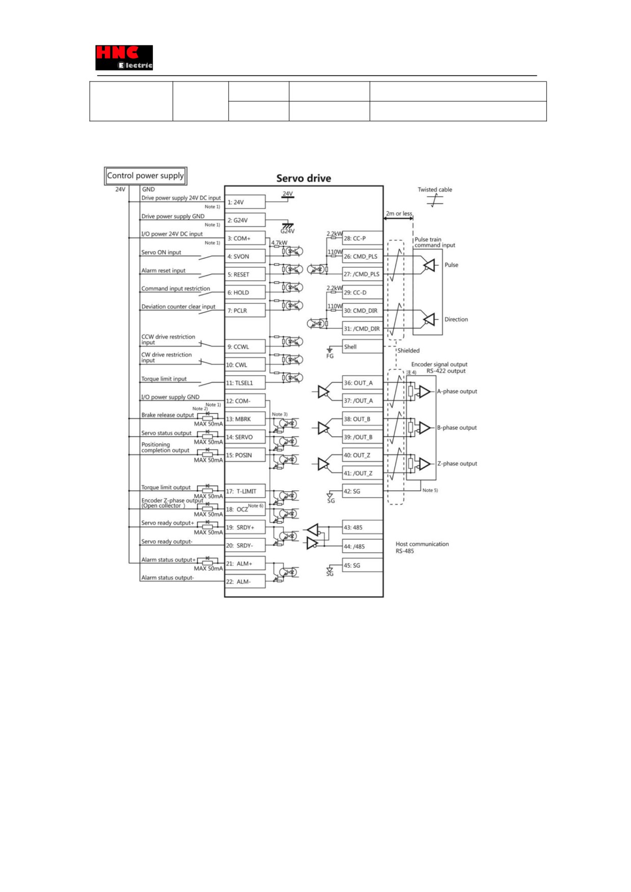
Note 1)Control power supply(24V, G24V) and I/O power (COM+, COM-) share the same power supply(For the models of
750W or less).
Note 2)If there is drive inductive load(relay), please use protective circuits(diode).
Note 3) Transistor output is an open collector output circuit of the Darlington-connected. It should be connected with relay or
optocoupler. Please don’t connect transistor directly because the voltage VCE(SAT) between collector and emitter is about
1V which cannot meet the required voltage VIL of TTL IC when transistor is ON.
Note 4) Terminal resistance must be connected as shown in the wiring diagram.
Note 5) Connect the signal ground on the host control device of output signal of the encoder. The connection of signal ground
and power supply GND may cause malfunction.
Note 6) If the pulse width of Z-phase is too narrow to identify the host control device, please reduce the encoder pulse output
94
division and multiplication No.276.0, 278.0 or reduce the speed to increase the pulse width.[Pulse width]=1/speed/(division
and multiplication×217).
8.2.2 Pulse position command input (24V open collector input)
Name
Symbol
Terminal
Signal name
Contents
No.
User I/O
CN1
1
24V
Drive control power supply 24V input
●24V power
2
G24V
Drive control power supply GND
supply input
3
COM+/-
I/O power supply 24V input
●Parallel I/O
4
SVON
Servo ON input
●Pulse command
5
RESET
Alarm reset input
input
6
HOLD
Command input restriction
●ABZ output
7
PCLR
Deviation counter clear input
8
-
Reserved
9
CCWL
CCW drive input restriction
10
CWL
CW drive input restriction
11
TLSEL1
Torque limit input
12
COM-
I/O power supply GND
13
MBRK
Brake release output
14
SERVO
Servo status output
15
POSIN
Position completion output
16
-
Reserved
17
T-LIMIT
Torque limit output
18
OCZ
Encoder Z-phase output (open collector)
19
SRDY+
Servo ready output +
20
SRDY-
Servo ready output -
21
ALM+
Servo alarm output+
22
ALM-
Servo alarm output-
23
NC1
Reserved (Disconnected)
24
-
Reserved
25
-
Reserved
26
CMD_PLS
Reserved
27
/CMD_PLS
Pulse command, pulse, orthogonal phase
difference A-phase, CCW
28
CC-P
24V for pulse command PSL
29
CC-D
24V for pulse command DIR
30
CMD_DIR
Reserved
31
/CMD_DIR
Pulse command, direction, orthogonal phase
difference B-phase, CW
95
32
-
Reserved
33
-
Reserved
34
-
Reserved
35
-
Reserved
36
OUT_A
Encoder A phase output
37
/OUT_A
Encoder /A phase output
38
OUT_B
Encoder B phase output
39
/OUT_B
Encoder /B phase output
40
OUT_Z
Encoder Z phase output
41
/OUT_Z
Encoder /Z phase output
42
SG
Signal ground
43
485
RS-485 communication data
44
/485
RS-485 communication /data
45
SG
Signal ground
46
NC2
Reserved(Disconnected)
47
-
Reserved
48
-
Reserved
-
49
Reserved
-
50
Reserved
96
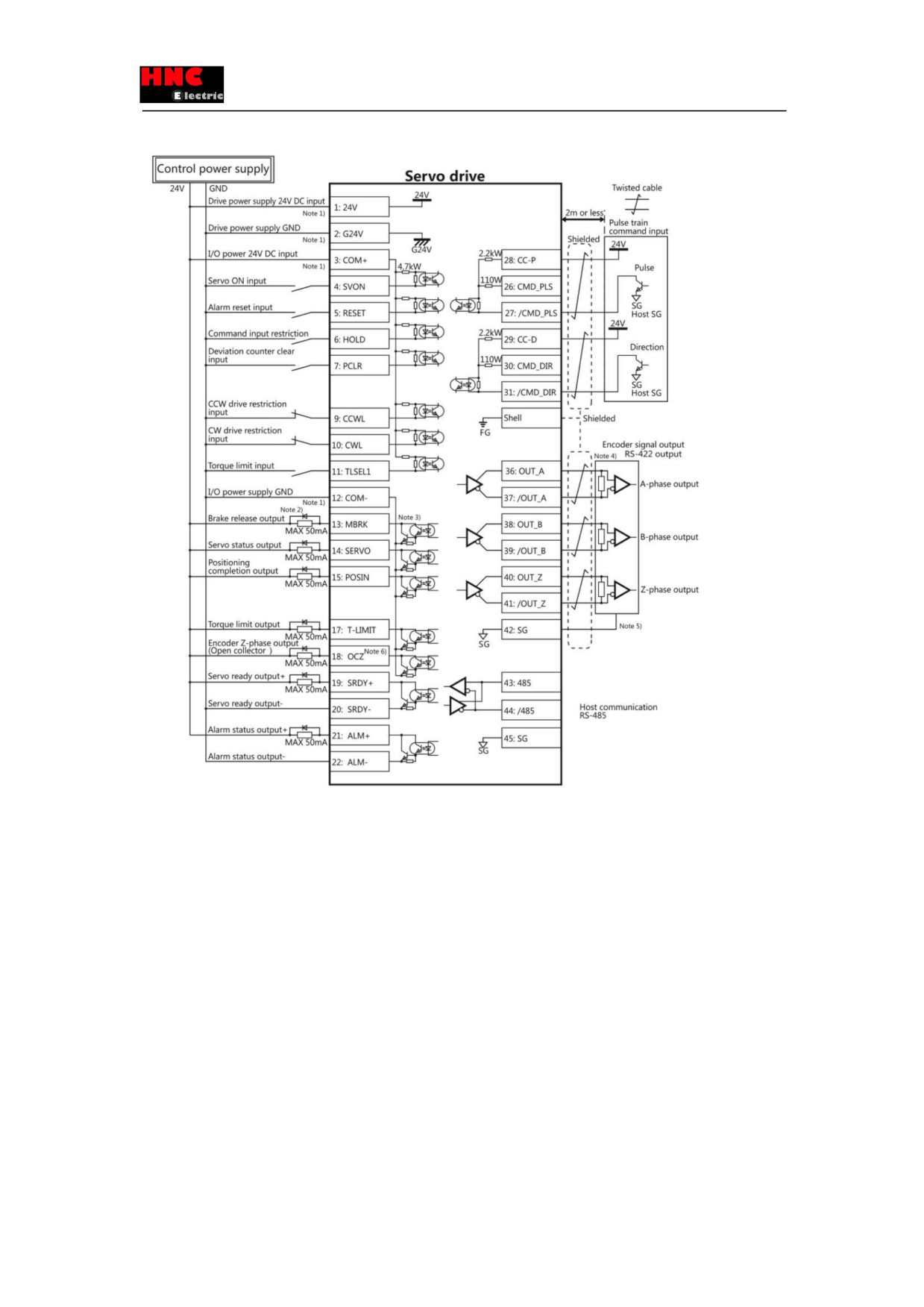
Note 1)Control power supply(24V, G24V) and I/O power (COM+, COM-) share the same power supply(For the models of
750W or less).
Note 2)If there is drive inductive load(relay), please use protective circuits(diode).
Note 3) Transistor output is an open collector output circuit of the Darlington-connected. It should be connected with relay or
optocoupler. Please don’t connect transistor directly because the voltage VCE(SAT) between collector and emitter is about
1V which cannot meet the required voltage VIL of TTL IC when transistor is ON.
Note 4) Terminal resistance must be connected as shown in the wiring diagram.
Note 5) Connect the signal ground on the host control device of output signal of the encoder. The connection of signal ground
and power supply GND may cause malfunction.
Note 6) If the pulse width of Z-phase is too narrow to identify the host control device, please reduce the encoder pulse output
division and multiplication No.276.0, 278.0 or reduce the speed to increase the pulse width.[Pulse width]=1/speed/(division
and multiplication×217).
8.2.3 Pulse position command input (5V open collector input)
97
Name
Symbol
Terminal
Signal name
Contents
No.
User I/O
CN1
1
24V
Drive control power supply 24V input
●24V power
2
G24V
Drive control power supply GND
supply input
3
COM+/-
I/O power supply 24V input
●Parallel I/O
4
SVON
Servo ON input
●Pulse command
5
RESET
Alarm reset input
input
6
HOLD
Command input restriction
●ABZ output
7
PCLR
Deviation counter clear input
8
-
Reserved
9
CCWL
CCW drive input restriction
10
CWL
CW drive input restriction
11
TLSEL1
Torque limit input
12
COM-
I/O power supply GND
13
MBRK
Brake release output
14
SERVO
Servo status output
15
POSIN
Position completion output
16
-
Reserved
17
T-LIMIT
Torque limit output
18
OCZ
Encoder Z-phase output (open collector)
19
SRDY+
Servo ready output +
20
SRDY-
Servo ready output -
21
ALM+
Servo alarm output+
22
ALM-
Servo alarm output-
23
NC1
Reserved (Disconnected)
24
-
Reserved
25
-
Reserved
26
CMD_PLS
5V for pulse command PLS
27
/CMD_PLS
Pulse command, pulse, orthogonal phase
difference A-phase, CCW
28
CC-P
Reserved
29
CC-D
Reserved
30
CMD_DIR
5V for pulse command DIR
31
/CMD_DIR
Pulse command, direction, orthogonal phase
difference B-phase, CW
32
-
Reserved
33
-
Reserved
98
34
-
Reserved
35
-
Reserved
36
OUT_A
Encoder A phase output
37
/OUT_A
Encoder /A phase output
38
OUT_B
Encoder B phase output
39
/OUT_B
Encoder /B phase output
40
OUT_Z
Encoder Z phase output
41
/OUT_Z
Encoder /Z phase output
42
SG
Signal ground
43
485
RS-485 communication data
44
/485
RS-485 communication /data
45
SG
Signal ground
46
NC2
Reserved(Disconnected)
47
-
Reserved
-
48
Reserved
CC-P(5V)
49
5V for pulse command PLS (Built in current
limiting resistor )
50
CC-D(5V)
5V for pulse command DIR (Built in current
limiting resistor )
99