SERVO DRIVE SV-E3 SERIES. INSTRUCTION MANUAL (v1.5) - page 4
Smoothing filter 1
average moving times
81. 0
*1) The marking method varies from the drive version. The version of
3. 5. 1.
0 or before is marked with [Selection of position
command smoothing filter 1]
*2) The marking method varies from the drive version. The version of
3. 5. 1.
0 or before is marked with [Selection of position
command smoothing filter 2]
Types
Names
No.
Torque command
Low-pass filter
Switch
160. 0
filter
Auto setting
160. 2
Time constant
162. 0
Notch filter
Switch
160. 1
Frequency
168. 0
Width
169. 0
Depth
170. 0
Pulse command
Input pulse types
32. 0
Rotation direction
32. 1
Input logic
32. 3
Division and
Interpolation
32. 2
multiplication
Numerator
34. 0
Denominator
36. 0
Input filter
33. 0
Feedforward Delay compensation
66. 3
Positioning
Determination method
64. 0
completion
Detection
Range
68. 0
Speed
69. 0
Command input
70. 0
Detection delay time
71. 0
Internal position
Operation mode
642. 0
Overflow detection
643. 0
Point table
Point No. output method
644. 0
Operation of point No. 0
646. 3
Command method
720. 0~
Operation conditions
720. 1~
Valid or Invalid
720. 3~
Position
722. 0~
Rotation speed
724. 0~
Acceleration speed
726. 0~
Deceleration speed
727. 0~
Dwell time
728. 0~
Positioning completion
729. 0~
Home position
Home position DOG redetection operation
645. 3
return
Moving direction
646. 0
Sensor DOG polarity
646. 1
Timeout limit
Switch
646.2
60
Time
659. 0
Torque limit
Switch
647. 0
Value
656. 0
Home position return Press detection time
655. 0
Creep switch
647. 1
Operation speed
648. 0
Creep speed
649. 0
Acceleration/deceleration time
650. 0
Home position travel distance
651. 0
Home position data
653. 0
Home position return Phase Z invalidation distance
657. 0
Selection of home position base signal
645. 0
Selection of encoder phase Z
645. 1
Analog speed
Offset
Adjustment
62. 2
Value
60. 0
Rotation direction
62.0
Input filter
Switch
62. 1
Numerator
48. 0
Denominator
49. 0
Input gain
Numerator
50. 0
Denominator
51. 0
Speed limit
CCW
Numerator
52. 0
Denominator
53. 0
CW
Numerator
54. 0
Denominator
55. 0
Smoothing filter
Switch
77. 0
Average travel time
78. 0
Internal speed
Command method
388. 0
Acceleration time
390. 0
Deceleration time
391. 0
Speed 1 to 8
392. 0~
Analog torque
Offset
Adjustment
302. 2
Value
300. 0
Rotation direction
302. 0
Input filter
Switch
302. 1
Numerator
288. 0
Denominator
289. 0
Input filter
Numerator
290. 0
Denominator
291. 0
Torque limit
CCW
Numerator
292. 0
Denominator
293. 0
CW
Numerator
294. 0
Denominator
295.0
61
Speed limit
152. 0
Table
6.1.2 Parameter list
No
Parameter
Contents
Whether to
restart control
power supply
002.0r
[Basic setting]
Control mode selection.
Yes
Control mode
Note) Do not change when servo is ON.
0= Position control mode
1= Speed control mode
2= Torque control mode
[Initial value] 0 (Position control mode)
[Setting range] 0 to 2
003.0r
[Basic setting]
Command mode selection
Yes
Command mode
0= Zero command (select in position control/ speed control mode)
selection
1= Pulse command (Used in position control)
2= Analog command (Used in speed control)
3= Internal generation command (Used in speed control)
[Initial value] 1 (Pulse train command )
[Setting range] 0 to 3
004.0r
[Basic setting]
Set the communication address of servo drive.
Yes
Communication
Set to “1” when not using RS-485 multi-station communication. If using multi-station
address
communication, refer to 「RS-485 communication wiring」. Setting different values for
each axis.
[Initial value] 1
[Setting range] 1 to 32
008.0
[Basic setting]
Select host communication mode.
No
Selection of host
0= Disable
communication
1= RS-485 asynchronous serial communication
mode
When connecting RS-485 signal cable and using RS-485 asynchronous serial
communication, select to “1”. If not, select to “0”.
If the USB is irrelevant to this setting, it can communicate anytime.
[Initial value] 0 (Disable)
[Setting range] 0 or 1
009.0
[Basic setting]
Select the operation mode.
No
Operation mode
0=I/O
selection
1=Communication
[Initial value] 0(I/O)
[Setting range] 0 or 1
011.0
[Basic setting]
Set the minimum response time for RS485 communication
Yes
RS485
The response time of drive can be adjusted according to the minimum response time.
communication
For details, refer to [Communication time] of [Communication interface].
minimum
[Initial value] 3
62
response time
[Setting range] 0 to 255
032.0r
[Basic setting]
Select pulse signal type of pulse command input.
Yes
Pulse train
0= Pulse and direction: using pulse and direction input
command
1= Orthogonal phase difference: using orthogonal phase pulse (A-phase/B-phase)
input mode
input
2= CCW/CW: using positive pulse and negative pulse
[Initial value] 0 (Pulse/direction)
[Setting range] 0 to 2
032.1r
[Basic setting]
Select rotation direction of pulse
command input
Yes
Pulse train
0: CCW addition counting
command
1: CCW subtraction counting
Rotation direction
[Initial value] 1 (CCW addition counting)
[Setting range] 0 or 1
032.2r
[Basic setting]
When setting command division/ multiplication, the command will be processed by
Yes
With(out) use of
smoothing interpolation automatically.
automatic
0= Disable
command
1= Enable
interpolation for
[Initial setting] 1 (Enable)
division/
[Setting range] 0 or 1
multiplication
032.3
[Basic setting]
Select the logic for pulse train input.
Yes
Selection of Pulse
0= Positive logic : Up counting from Low to High
train input logic
1= Negative logic: Downing counting from High to Low
[Initial setting] 0 (Positive logic)
[Setting range] 0 or 1
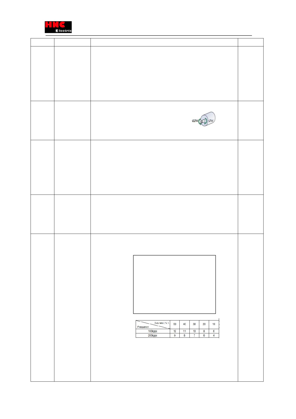
033.0r
[Basic setting]
The function of input filter is to reduce the fault caused by noise. Select the pulse width
Yes
Pulse command
of passing pulse command input.
input filter
0= No filter
selection
1= Pulse width 25ns
When pulse command is open collector
2= Pulse width 50ns
circuit, it is recommended to set the best
3= Pulse width 100ns
filter. The following table indicates the
4= Pulse width 150ns
corresponding filter optimum value between
5= Pulse width 200ns
input pulse frequency and pulse duty ratio.
6= Pulse width 300ns
Select the best value according to input pulse
7= Pulse width 400ns
frequency and pulse duty ratio.
8= Pulse width 600ns
9= Pulse width 800ns
10= Pulse width
1000ns
11= Pulse width 1200ns
12= Pulse width 1600ns
13= Pulse width 2000ns
14= Pulse width 2300ns
15= Pulse width 3100ns
63
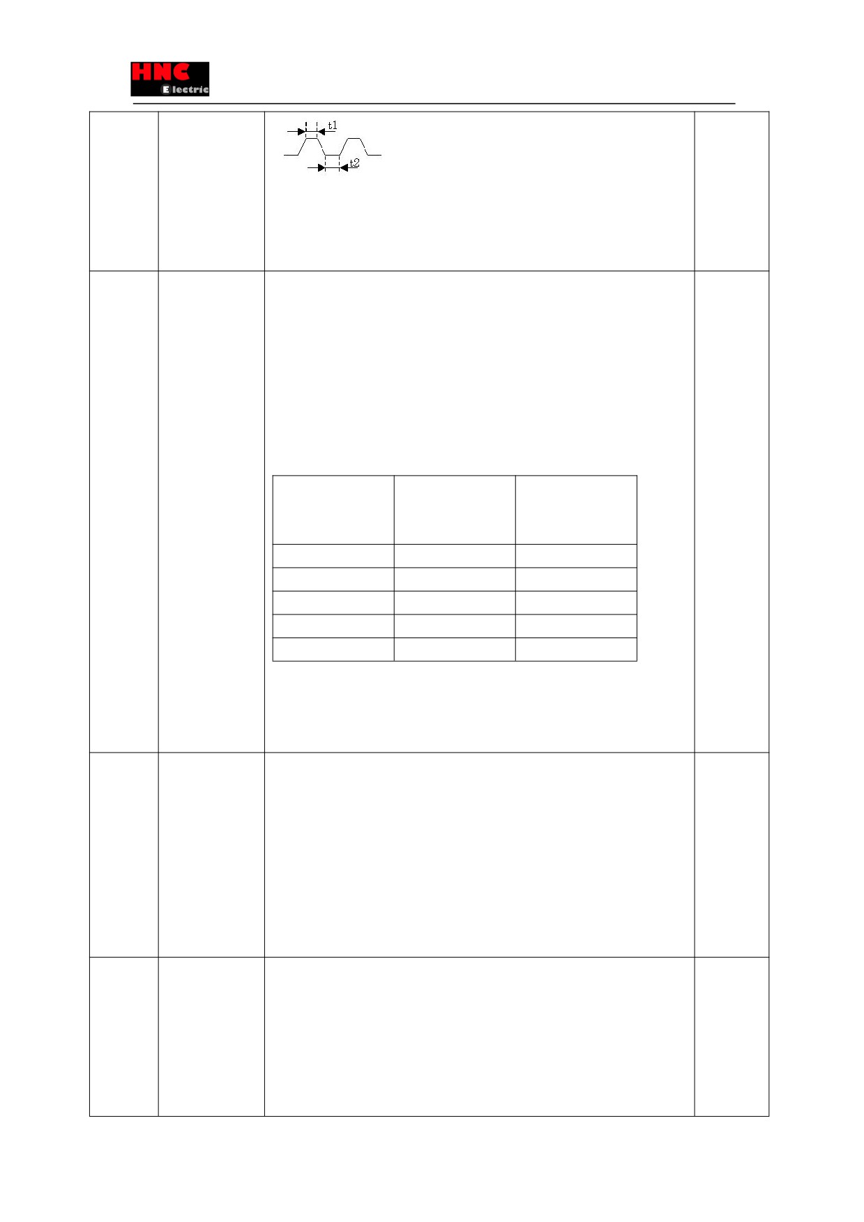
When the input frequency is high, please set the small passing pulse width. To improve
interference immunity, please set the large passing pulse width.
[Initial setting] 4 (Passing pulse width is 150ns or less)
[Setting range] 0 to 15
034.0r
[Basic setting]
Set the parameters of position command pulse division/ multiplication.
Yes
/ 036.0r
Division/
When the number of upper command pulse and motor pulse per revolution is different,
multiplication
calculate in terms of [(Numerator) / (Denominator )=(Number of pulse per servo motor
(Numerator /
revolution) / (Number of host command pulse per revolution)
Denominator )
[Setting example]
The number of pulse per motor revolution is 131072[pulse/rev]. Numerator can be set
32768 by a quarter of 131072. Denominator can be set by a quarter of the number of
upper command per revolution. The corresponding parameter setting of the number of
upper command pulse per revolution is as follows.
Number of host
Command division/
Command division/
command per
multiplication
multiplication
revolution
(Numerator)
(Denominator)
131072
1000(Initial value)
1000(Initial value)
16384
32768
4096
10000
32768
2500
4096
32768
1024
4000
32768
1000
[Initial value] (Numerator / Denominator ) =1000/1000
[Setting range] (Numerator) 1 to 65535, (Denominator) 1 to 65535.
Setting range of Division/ multiplication ratio is from 0.001 to 1000.Normal operation is
not guaranteed while division/ multiplication ratio is beyond setting range.
048.0 /
[Adjustment]
Low-pass filter parameter for smoothing analog speed command input.
No
049.0
Analog command
It is valid when input filter selection (No.062.1) is set “1”,.
input
Parameter decrease→Smoothing effect becomes stronger, command traceability
Filter parameter
reduces.
(Numerator /
Parameter increase→command traceability increases,, susceptible to interference
Denominator )
(Numerator / Denominator ) the value must be less than 1.
(Numerator / Denominator ) =1, filter invalid
[Initial setting] (Numerator / Denominator )= 16000/65535
[Setting range] 0~65535/1~65535
050.0 /
[Adjustment]
Gain of analog speed command input.
No
051.0
Analog command
When (Numerator) / (Denominator )=1 and ±10V analog command voltage is input,
input
the highest rotation speed of motor can be reached.
Gain
※As for the highest rotation speed of motor, refer to 「Basic specification」
(Numerator /
According to different choice of symbol and polarity for analog command voltage, the
Denominator )
rotation direction of motor is different.
Decreasing this value has the effect of decreasing proportional gain of position loop at
64
upper controller.
[Initial setting] (Numerator / Denominator )=1000/1000
[Setting range] 0~65535/1~65535
052.0 /
[Basic setting]
Analog speed command CCW speed limit threshold value.
No
053.0
Analog speed
Analog command CCW speed limit = (the highest speed of motor) * (threshold
command CCW
value(numerator))/ (threshold value(denominator))
speed limit
[initial setting] (Numerator / Denominator )=5000/5000
threshold value
[Setting range] 0~65535/1~65535
(Numerator /
Denominator )
054.0 /
[Adjustment]
Analog speed command CW speed limit threshold value.
No
055.0
Analog speed
Analog command CW speed limits = (the highest speed of motor) * (threshold
command CW
value(numerator))/ (threshold value(denominator))
speed limit
[initial setting] (Numerator / Denominator )=5000/5000
threshold value
[Setting range] 0~65535/1~65535
(Numerator /
Denominator )
060.0
[Basic setting]
When using manual adjustment to adjust offset value of analog speed command, set
No
Analog
speed
the adjustment value. It’s valid when the offset adjustment is selected to “1= manual
command
adjustment”. Adjust the corresponding analog speed command input to 0r/min at the
fixed offset value
0V input voltage.
<setting method>.
1. Servo ON (motor will rotate if offset exists)
2. When rotating at the speed of ± 10r/min or less, set the value to ±50 to confirm
the operation.
(CCW direction, set to「-50」; CW direction, set to「+50」.
3. Set the offset value while observing the motor operation. (If rotate at CCW direction,
setting values change in response to 「-direction」. If rotate at CW direction, setting
values change in response to 「+direction」.
[Initial value] 0
[Setting range] -32768/32768
062.0
[Basic setting]
Select rotation direction of analog speed command.
No
Analog
speed
0=Inputting negative voltage, the motor has CCW rotation; Inputting positive voltage,
command rotation
the motor has CW rotation.
direction
1= Inputting positive voltage, the motor has CCW rotation; Inputting negative voltage,
the motor has CW rotation.
[Initial value] 1 (Inputting positive voltage, the motor has CCW rotation)
[Setting range] 0 or 1
062.1
[Basic setting]
Select analog speed command input filter.
No
Select analog
Input filter constant can be set in No.048.0, No.049.0.
speed command
0= Disable
input filter
1=Enable (one IIR filter)
[Initial value] 1 (Enable)
[Setting range] 0 or 1
65

062.2
[Basic setting]
Select offset adjustment of analog speed command.
No
Select offset
0=Auto tuning
adjustment type of
1=Manual tuning
analog speed
Auto tuning works under the voltage which corresponds to 0r/min of speed command
command
while servo ON.
Manual tuning means input offset manually to make sure input voltage 0Vcorresponds
to speed command 0r/min. . Offset value can be adjusted by parameter No.60.0(fixed
offset value).
[Initial value] 1 (manual tuning)
[Setting range] 0 or 1
064.0
[Basic setting]
Select the output form of positioning completion signal.
No
Judgment
of
0=Position difference + speed
positioning
1=Position difference+ speed+ pulse command input(speed)
completion
When selecting 0, after the position difference is in the positioning completion range
No.68.0
and speed is in the range of positioning completion speed No.69.0,,
positioning completion signal will be output.
When selecting 1, after the position difference, speed and pulse
command
input(speed) are all in the range of
positioning completion range No.68.0
,
positioning completion speed No.69.0
and positioning pulse train command
input(speed) No.70.0 respectively, positioning completion signal will be output.
The delay time from positioning completion to output positioning completion signal can
be set in No.71.0.
[Initial setting] 0
[Setting range] 0 or 1
065.0
[Special setting]
Select whether to use position difference error detection. Usually set value to “1”.
No
With or without
(Enable)
use of position
Only when suing torque command limit, set to “0”. Set the position deviation value of
difference error
error detection by No.87.0 and set the delay time from position error occurred to output
detection
stop by No.89.0.
0=Disable
1=Enable
[Initial value] 1 (Enable)
[Setting range] 0 or 1
065.1
[Special setting]
Select whether to use speed deviation error detection. Usually set value is
No
With(out) use
of
“1”.( Enable)
speed deviation
Only when suing torque command limit, set “0”. Set the speed deviation value of error
error detection
detection by No.90.0 and set delay time from speed error occurred to output stop by
No.91.0.
0= Disable
1=Enable
[Initial value] 1 (Enable)
[Setting range] 0 or 1
066.0r and
[Adjustment]
Select position command smoothing filter1
(No.66.0) and position command
Yes
066.1r
With(out) use of
smoothing filter 2 (No.66.1)
66
position command
0=Disable
smoothing filter 1
1=Enable
and position
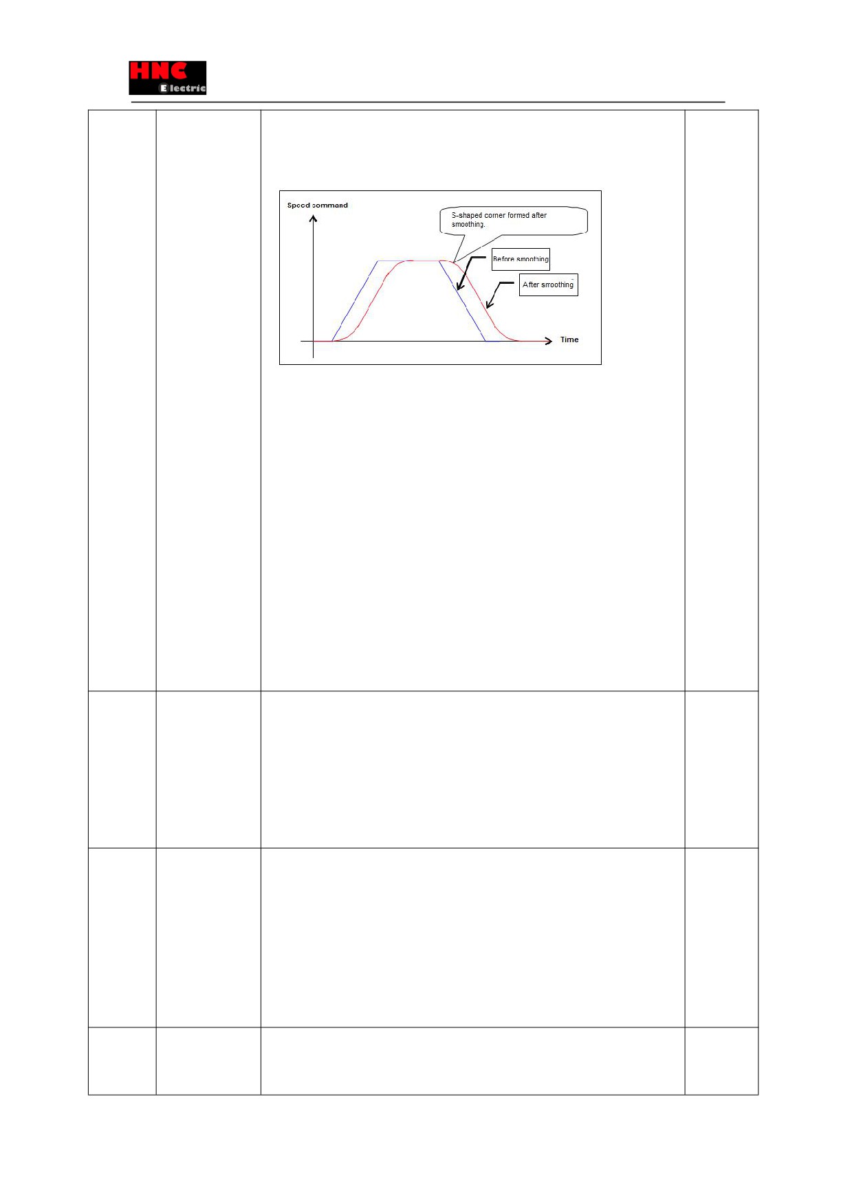
Command will be smooth as shown below after using a smoothing filter.
command filter 2
[Adjustment method]
Used when command acceleration or deceleration are too fast.
Used to suppress device resonance when positioning. Measuring the resonant
frequency in torque command curve and setting a corresponding average movement
number in position command smoothing filter1 moving average time No,80 or position
command smoothing filter2
average movement number No.81, may inhibit
resonance. The relation between resonant frequency and
average movement
number is stated under parameter specification of No.80 and No,81.
[Notes] This parameter can be set after more than 1.5s when the command pulse input
is 0. And the servo must be off while setting. If there is pulse input or residual pulse
setting, position difference will occur.
[Initial setting] Command smoothing filter 1 is ‘0”. (Not used)
Command smoothing filter 2 is ‘1”.(Used)
[Setting range] 0 or 1
066.3
[Special setting]
Enable/Disable Feed forward delay compensation in position control mode.
Yes
With(out) the Feed
0=Disable
forward delay
1= Enable
compensation in
<Note> Generally set to “1”. Do not make the changes and cannot be done on setting
position control
panel.
mode
[Initial setting] 1 (Enable)
[Setting range] 0 or 1
067.0r
[Adjustment]
Select the drive restriction options
Yes
Selection of drive
Note) Do not modify the parameter while the servo is ON.
restriction options
0=Invalid
1=CW restriction.
2=CCW restriction.
3= CW/CCW restriction.
[Initial setting] 0 (Invalid)
[Setting range] 0 to 3
067.1
[Basic setting]
Select deceleration method at drive restriction input.
No
Selection of
Note) Do not modify the parameter while the servo is ON.
deceleration
When using deceleration method No.67.1 and stopping method No.67.2, please follow
67
method at drive
the following combination methods.
restriction input
0=Free-run
1=Short brake
2= Prompt stop
Combin
Deceleration method
Stopping method
ation
No.67.1
No.67.2
1
0: Free-run
0: Free-run
2
1: Short brake
0; Free-run
3
2: Prompt stop
1: zero clamp
4
2: Prompt stop
0: Free-run
[Initial setting] 1
[Setting range] 0 to 2
067.2
[Basic setting]
Select stop status at drive restriction.
No
Selection of stop
Note) Do not modify the parameter while the servo is ON.
status at drive
When using deceleration method No.67.1 and stopping method No.67.2, please follow
restriction
the above combination methods.
0= Free-run
1= zero clamp
[Initial setting] 1
[Setting range] 0 or 1
067.3
[Basic setting]
Select position difference counter status at drive restriction
No
Selection of
Note) Do not modify the parameter while the servo is ON.
position difference
0= Keep
counter status at
1=Clear
drive restriction
[Initial setting] 1
[Setting range] 0 or 1
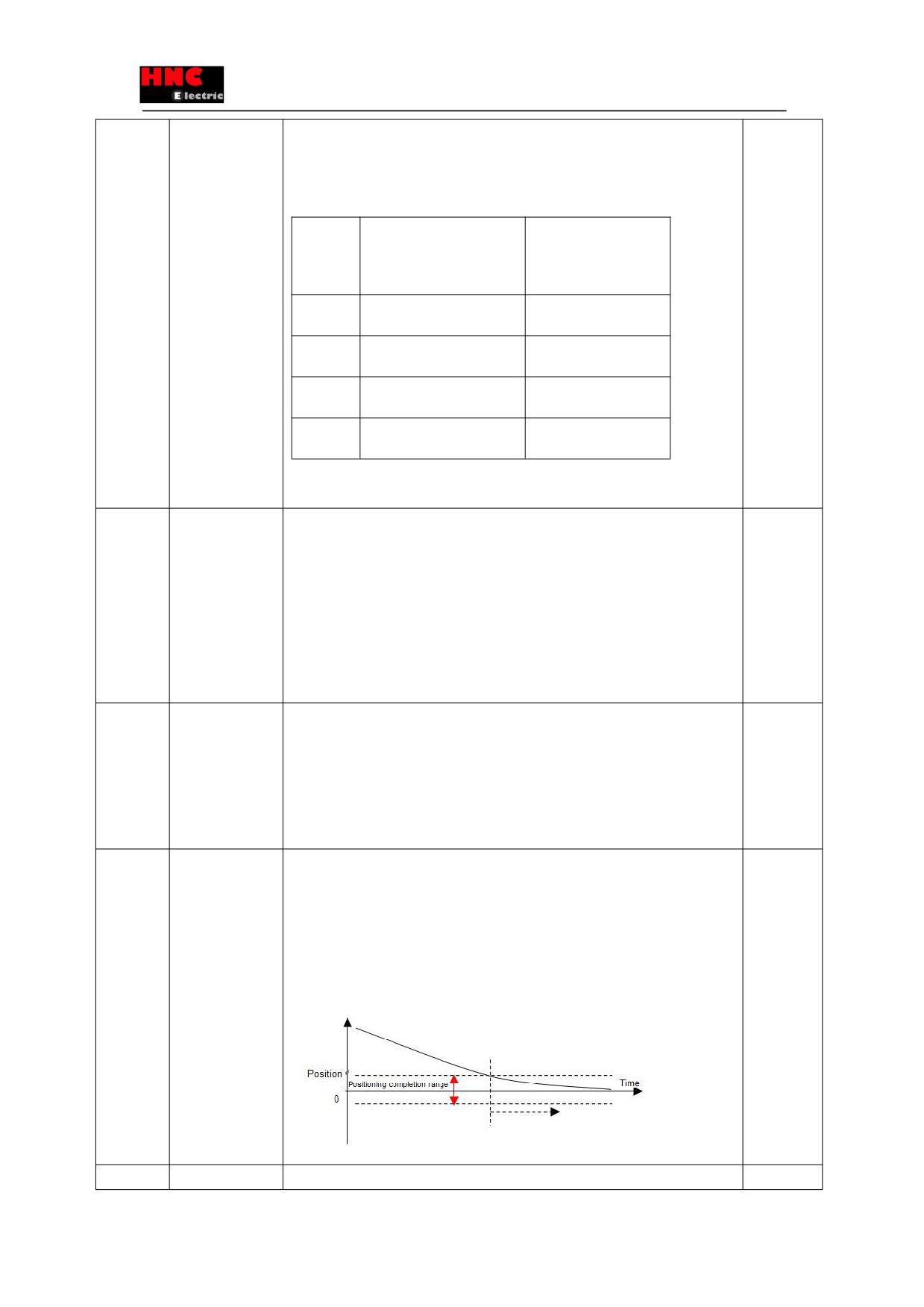
068.0
[Basic setting]
As the reference of outputting positioning completion signal to upper controller, this
No
Positioning
parameter is the pulse width for judging positioning completion.
completion range
The setting value should be less than the number of positioning judge pulse of upper
controller.
[Initial value] 40[Pulse](±40[pulse])
[Setting range] 0 to 32767
069.0
[Basic setting]
As the reference of outputting positioning completion signal to upper controller, this
No
68
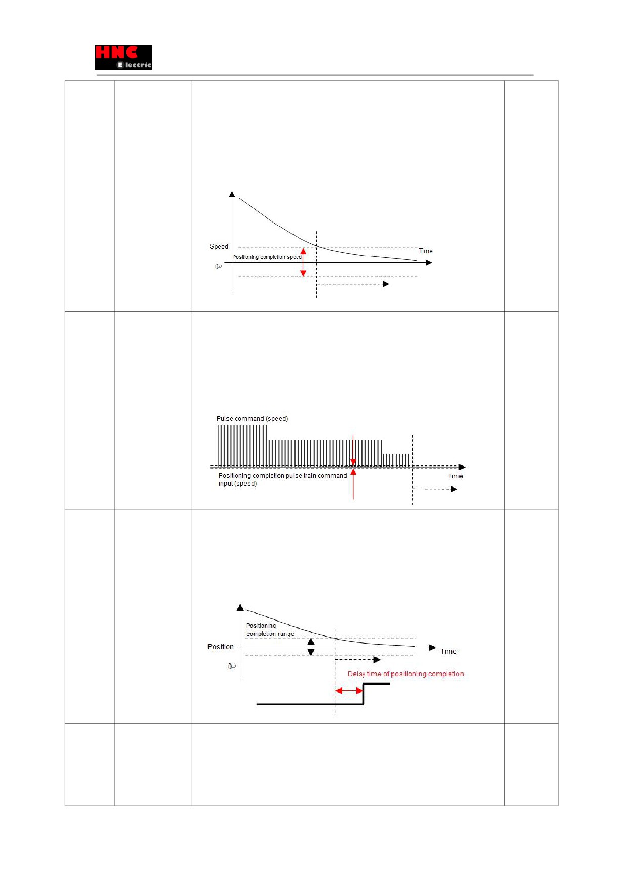
Positioning
parameter is the speed limit for judging positioning completion.
completion speed
The setting value should be less than the number of speed limit of upper controller.
[Initial value]
750W or less:2 [pulse/160μs]
(±2 [pulse/160μs] ・・・ 5.72[r/min]
1kW or more :
2
[pulse/200μs]
(±2 [pulse/200μs])・・・ 4.58[r/min]
[Setting range] 0 to 32767
070.0
[Basic setting]
As the reference of outputting positioning completion signal to upper controller, this
No
Positioning
parameter is the pulse command input(speed) for judging positioning completion
completion pulse
[Initial setting]
command input
750W or less: 0 [pulse/160μs]
(±0 [pulse/160μs])
(speed)
1kW or more:0
[pulse/200μs]
(±0 [pulse/200μs])
[Setting range] 0 to 32767
071.0
[Basic setting]
Select the delay time from positioning completion to output signal to upper controller.
No
Delay time of
[Initial value]
positioning
750W or less:20 [160μs]・・・ 3.2ms
completion
1kW or more:16 [200μs]・・・ 3.2ms
detection
[Setting range] 0 to 65000
077.0
[Adjustment]
Choose whether to use speed command smoothing filter. The average movement time
No
With(out) the use
can be set in No.78.0.
of
speed
0=Disable
command
1=Enable
smoothing filter
[Initial value] 0
69
[Setting range] 0 or 1
078.0
[Adjustment]
Set the average movement time of speed command smoothing filter.
No
Average
It can be used when No.77.0 is effective.
movement time of
[Initial value] 100 [ms]
speed command
[Setting range] 1 to 1000
smoothing filter
080.0r and
[Adjustment]
Set the position command smoothing filter 1 to “1(Used)” in No.66.0 to make No.80.0
Yes
081.0r
Average
valid.
movement
Set the position command smoothing filter 2 to “1(Used)” in No.66.1 to make No.81.0
number of position
valid.
command
When the setting value of average movement number increases, the acceleration/
smoothing filter 1
deceleration will be smooth, but the response will be slow.
and average
Setting filter 1, the average movement number can be set between 1 and 6250; setting
movement
filter 2, the average movement number can be set between 1 and 1250.
number of position
The average movement time can be represented by the following formula.
command
200~750W: (average movement time)=(average movement number) ×0.16ms
smoothing filter
2
1k~2kW: (average movement time)=(average movement number) ×0.2ms
[Adjustment method]
● Smoothing will make positioning time longer in response to above average
movement time. Please have settings within the permissible range..
● When resonant occurs at constant move after acceleration or positioning after
deceleration, measuring the resonant frequency in torque command curve and setting
a corresponding average movement number in position command smoothing filter1
moving average time No,80
or position command smoothing filter2
average
movement number No.81, may inhibit resonance. The calculation of average
movement number and its corresponding suppressed resonance frequency is shown
below.
750W or less: Setting value of smoothing filter=6250/(suppressed vibration
frequency[Hz])
1kW or more: Setting value of smoothing filter=5000/(suppressed vibration
frequency[Hz])
Average movement number No.080.0,
64
256
1024
4096
No.081.0
750W or less: suppressed vibration
100
23
6
1.5
frequency(Hz)
1kW or more: suppressed vibration
80
20
5
1.2
frequency(Hz)
●The vibration caused by gain FF compensation 2 can be suppressed by position
command smoothing filter 2.
When using gain FF compensation 2 No.117.0, vibration can be reduced by using the
average movement number of position command smoothing filter 1 and filter 2.
[Notes] This parameter can be set when the command pulse input is “0” for more
than 1.5s and there is no command pulse input. If possible, it is recommended to turn
off the servo. If you set the parameter when there is pulse input or residual pulse,
70
position shift will occur.
[Initial value] Filter 1: 25 for 200~750W, 20 for
1k~2kW
Filter 2: 10 for 200~750W, 10 for 1k~2kW
[Setting range] 1 to 6250 for filter 1, 1 to 1250 for filter 2.
087.0
[Special setting]
When set No.65.0 to “1(enable)”, it is valid to detect the position deviation errors.
No
Position deviation
Normally it’s effective.
error detection
When the position deviation exceeds the setting value, the output position deviation
value
errors occur.
It is more difficult to detect the position deviation if the value is greater.
[Initial value] 196608[pulse]
(※Equivalent to the number of 1.5 turns pulse)
[Setting range] 0 to 2147483647.
089.0
[Special setting]
When set No.65.0 to “1(enable)”, it is valid to detect the position deviation errors.
No
Delay time of
The time is from exceeding setting value 「Position deviation error detection value」
position deviation
to outputting position deviation error signal.
error detection
It takes longer from error occurred to error output when the value is greater.
[Initial value]
200~750W:
250 [160μs]・・・ 40ms
1k~2kW:
200
[200μs]・・・ 40ms
[Setting range] 0~32767
090.0
[Basic setting]
When set No.65.1 to “1(enable)”, it is valid to detect the speed deviation errors.
No
Speed deviation
Normally it’s effective. When the speed deviation exceeds setting detection value,
error detection
speed deviation error occurs.
value
It is more difficult to detect speed deviation error if the value is greater.
[Initial value] 200~750W:524[pulse/160μs]
・・・ 1499[r/min]
1k~2kW:
655[pulse/200μs]
・・・ 11499[r/min]
[Setting range] 0 to 32767
091.0
[Special setting]
When set No.65.1 to “1(enable)”, it is valid to detect the speed deviation error.
No
Delay time of
Normally it is effective.
speed deviation
The time is from exceeding setting value 「Speed deviation error detection value」 to
error detection
output speed deviation error signal.
It takes longer from error occurred to error output stopped when the value is greater.
[Initial value] 200~750W:
250
[160μs]
・・・ 40ms
1k~2kW: 200
[200μs]・・・ 40ms
[Setting range]
0 to 32767
102.0
[Adjustment]
Set Inertia ratio by the device load .
No
Inertia ratio
[Initial value] 250 [%]
[Setting range] 100 to 3000
103.0
[Adjustment]
Set Damping ratio on the device side. When the friction and inertia ratio is very big, the
No
Damping ratio
change of damping ratio value may shorten the setting time.
[Initial setting] 100
[%]
[Setting range] 10 to 5000
110.0
[Adjustment]
Setting of auto tuning mode.
No
With or without the
If the movement direction of machine connected to the motor is horizontal, select
use of estimated
“standard mode”. If vertical, select “Unbalanced mode”.
71
inertia ratio
1=Standard mode
1=Unbalanced mode
[Initial value] 1 (Standard mode)
[Setting range] 1 to 2
110.1
[Adjustment]
Select whether to use real-time auto tuning.
No
With(out) the use
0 = Disable
of real-time auto
1 = Enable and Apply Inertia ratio
tuning
2 = Enable and Apply Inertia ratio and Dumping ratio
[Initial value] 0 (Disable)
[Setting range] 0 to 2
113.0
[Adjustment]
Set the control gain level in position control mode. If traceability to command is slow or
No
Control gain level
rigidity of drive system is low, set a lower value; If traceability to command is rapid or
(position control)
rigidity of drive system is high, set a higher value.
When setting this parameter, No. 115.0~119.0 will be set automatically and No.114.0
becomes invalid.
[Initial value] 15
[Setting range] 5 to 45
113.1
[Adjustment]
Set the inertia condition of position control mode.
No
Inertia condition
0= Can interchange with F/W version of 2.0.4.0 or prior
1= For the device of heavy load and low rigidity, or large load changes
2= Standard setting
3= For the device of light load and CW/CCW frequently
[Initial value] 2 (Standard)
[Setting range] 0 to 3
114.0
[Adjustment]
Set control level of position control mode. If traceability to command is slow or rigidity
No
Control level
of drive system is low, set the lower value; If traceability to command is rapid or rigidity
(position control)
of drive system is high, set the higher value.
When setting this parameter, No.
115.0, No.116.0
will be set automatically and
No.113.0 becomes invalid.
When the inertia condition No.113.1 is set to “0”(servo drive version 2.0.4.0 or prior),
the setting range is from 1 to 46.
[Initial value] 15
[Setting range] 5 to 45
115.0
[Adjustment]
Set the Control gain 1 at position control mode. Higher setting value can shorten the
No
Control gain 1
setting time. Set the Control gain 2 as the following values.
(position control)
[Initial value] 50 [rad/s]
[Setting range] 5 to 1000
116.0
[Adjustment]
Set the Control gain 2 at position control mode. Higher setting value can improve the
No
Control gain 2
traceability to the command. Too high setting value can cause overshoot and vibration.
(position control)
When No.113.0 control gain level or No.114.0
control level is adjusted to set
automatically, sometimes the setting values will exceed the setting range.
[Initial value] 200[rad/s]
[Setting range] 80 to 5000
117.0
[Adjustment]
Set feed forward compensation ratio (speed) of the Control gain 1 in position control
No
72
Gain FF
mode. After confirming inertia ratio, adjusting this parameter will shorten the setting
compensation 1
time. Too high setting value will lead to overshoot. And too low setting value will make
(position control)
setting time longer.
[Initial value] 10000[0.01%]
[Setting range] 0 to 15000
118.0
[Adjustment]
Set feed forward compensation ratio (torque) of the control gain 2 in position control
No
Gain FF
mode. It is suitable to adjust this parameter when it requires small following error and
compensation 2
precise trajectory.
After Gain FF compensation 1 shortens setting time, please
(position control)
increase this parameter value. If vibration occurs, adjusting No.81.0 position command
smoothing filter 2 average movement times may suppress the vibration.
[Initial setting] 0 [0.01%]
[Setting range] 0 to 15000
119.0
[Adjustment]
Setting integral gain in position control mode can suppress external interference.
No
Integral gain
When the setting value is higher, the position deviation convergence of positioning
(position control)
setting will become fast. But if setting value is too high, vibration will occur.
When No.113.0 control gain level or No.114.0
control level is adjusted to set
automatically, sometimes the setting values will exceed the setting range.
[Initial value] 160[rad/s]
[Setting range] 45 to 5000
129.0
[Adjustment]
Select control gain level in speed control mode. If traceability to command is slow or
No
Control gain level
rigidity of drive system is low, set the lower value; If traceability to command is rapid or
(speed control)
rigidity of drive system is high, set the higher value.
When setting this parameter, No. 131.0~133.0 will be set automatically and No.130.0
becomes invalid.
[Initial value] 15
[Setting range] 1 to 46
130.0
[Adjustment]
Select control level in speed control mode. If traceability to command is slow or rigidity
No
Control level
of drive system is low, set the lower value; If traceability to command is rapid or rigidity
(speed control)
of drive system is high, set the higher value.
When setting this parameter, No.
131.0
will be set automatically and No.129.0
becomes invalid.
[Initial value] 15
[Setting range] 1 to 46
131.0
[Adjustment]
Set the control gain in speed control mode.
No
Control gain 1
It corresponds to proportional gain of speed control loop.
(speed control)
[Initial value] 399[rad/s]
[Setting range] 100 to 6000
132.0
[Adjustment]
Set feed forward compensation in speed control mode. The higher the setting value,
No
Gain FF
the better the traceability to command. But Too high setting value may lead to
compensation 1
overshoot or vibration
(speed control)
[Initial value] 0 [0.01%]
[Setting range] 0 to 15000
133.0
[Adjustment]
Select integral gain in speed control mode.
No
Integral
The higher the setting value, the smaller the speed change caused by external
73
gain(speed
disturbance.
control)
[Initial value] 300[rad/s]
[Setting range] 45 to 5000
144.0
[Basic setting]
Select torque command limit value in No.147.0, No.148.0
No
With or without the
Confirm the following items when using torque limit.
use of torque
①「No.65.0 Selection of Position deviation error detection」, please set it to
command limit
override
“0=Disable”
②「No.65.1 Selection of Speed deviation error detection」, please set it to “0=
Disable”
When the command deviation value is small, even though the torque limit is set to be
valid, it will be OK to set ① or ② to “1(enable)”.
0= Disable
1= Enable
[Initial setting] 0 (Disable)
[Setting range] 0 or 1
144.1
[Basic setting]
Select the output condition for torque limit.
No
Torque limit state
0= All conditions
output mode
(Torque is limited by torque command limit value 1 (No.147.0), max. torque limit value
of motor and torque limit value of home position return (No. 656.0), not limited by
speed in torque control mode)
1= Torque command limit Override 1 (No.147.0) or 2 (No.148.0)
2= Torque command limit Override 2 (No.148.0)
[Initial setting] 0 (All conditions)
[Setting range] 0 to 2
147.0
[Basic setting]
It is valid when No.144.0 torque command limit override is set to “1(enable)”.
No
148.0
Torque command
Set torque command limit override relative to rated torque ratio.
limit override 1, 2
Tow torque limits could be set.
[Initial value] 3000[0.1%] for torque limit 1; 2000[0.1%] for torque limit 2
[Setting range] 0 to 65535
151.0
[Basic setting]
Set the torque command limit override relative to rated torque, if the stop type in
No
Torque command
No.224.0 is set to “2=prompt stop” when servo is OFF.
limit override at
prompt stop
[Initial value]
5000[0.1 % ] (When set 3000 or more, the limit value of max. torque
command is 300%. If the setting value is bigger than 1000 , overload error will occur
according to overload characteristics specified time.
[Setting range] 0 to 65535
152.0
[Basic setting]
Set Speed limit value of analog torque control mode.
No
Analog torque
[Initial value] Max. speed of the motor
command speed
[Setting range] 0 to 10000
limit value
160.0
[Adjustment]
Select torque command low-pass filter.
No
74
Selection of torque
0=No filter
command
1= Preliminary IIR filter
low-pass filter
[Initial value] 1 (Preliminary IIR filter)
[Setting range] 0 or 1
160.1
[Adjustment]
Whether the notch filter is used to set the torque command.
No
Torque command
0=Disable
Selection of
1=Enable
whether to use
[Initial value] 0 (Disable)
notch filter
[Setting range] 0 or 1
160.2
[Adjustment]
Select whether to use the auto setting for torque command low-pass filter in control
No
Auto setting
gain level (No. 113 and No. 129).
ON/OFF for
0 = Auto setting OFF
Torque command
1 = Auto setting ON
Low-pass filter
[Initial value] 1 (Auto setting ON)
[Setting range] 0 or 1
162.0
[Adjustment]
Set the torque command preliminary filter time constant for Low-pass filter
No
Torque command
[Initial value] 20
[0.01ms]
preliminary filter
[Setting range] 0 to 65535
time constant for
Low-pass filter
168.0
[Adjustment]
Set Notch filter notch frequency of Torque command
No
Torque command
[Initial value] 5000[Hz]
notch filter
[Setting range] 0 to 5000
frequency
169.0
[Adjustment]
Set notch filter width of torque command.
No
Torque command
Set the ratio relative to a frequency band with 0 notch depth and -3[dB] attenuation
Notch filter width
rate. The larger the value, the greater the width of the notch
[Initial value] 8
[Setting range] 0 to 16
170.0
[Adjustment]
Set the notch depth at the notch frequency of torque command notch filter,
No
Torque command
Set the I/O ratio of notch frequency. When the setting value is 0, the notch frequency
Notch filter depth
input is completely cut off. When the setting value is 256, the notch frequency input is
completely through. The notch depth becomes shallow when the value is bigger.
[Initial value] 0
[Setting range] 0 to 256
224.0
[Basic setting]
Select the deceleration stop type when the alarm occurs or servo ON signal is off in
No
Type selection
motor revolution.
deceleration stop
0=No brake
at servo OFF
1=Short brake mode
2= Prompt stop
[Initial value] 1 (Short brake mode)
[Setting range] 0 to 2
224.1
[Basic setting]
Select cancellation reasons for deceleration stop at servo OFF
No
Deceleration stop
0=Operatingtime
75
at Servo off:
1 = Rotations of cancelation or operating time
cancelation
[Initial value] 1 (Rotations of cancelation or operating time)
reasons
[Setting range] 0 or 1
224.2
[Basic setting]
Enable/Disable Deceleration Stop when the voltage from a control power supply drops
No
Use of a
by No. 228.0.
deceleration stop
0 = Disable
in case of control
1 = Enable
power supply
[Initial value] 1 (Enable)
voltage drop
[Setting range] 0 or 1
226.0
[Basic setting]
Set the operating time for deceleration stop at servo OFF.
No
Deceleration stop :
(If “0(No brake)” is set to No.224, this parameter is invalid.)
operating time at
[Initial value] 200W~750W: 313 [160μs] ・・・ 50ms,
servo off
1kW~2kW: 250 [200μs] ・・・ 50ms
[Setting range] 0 to 16383
227.0
[Basic setting]
Set the cancellation speed of deceleration stop at servo OFF. It sets the speed of
No
Cancellation
brake OFF cancellation.
speed of
(If
“0(No brake)” is set to No.224.0 and “0(Operation time)” set to No.224.1, this
deceleration stop
parameter is invalid.)
and brake
[Initial value] 200W~750W: 17[pulse/160μs] ・・・ 50r/min,
cancellation OFF
1kW~2kW: 22[pulse/200μs] ・・・ 50r/min
at servo OFF.
[Setting range] 0 to 32767
228.0
[Basic setting]
Set the operating time of deceleration stop at control power supply voltage drop in
No
Operating time of
motor rotation.
deceleration stop
[Initial value] 62 [160μs] ・・・ 10ms
at control power
[Setting range]
0 to 16383 [ms]
supply voltage
drop
237.0
[Basic setting]
Set the delay time between getting the input signal of Servo OFF and motor excitation
No
Delay time at
OFF.
servo OFF
(The disconnection of COM2 and SVON terminal indicates the servo ON input signal
is OFF.)
[Initial value]
200W~750W: 0[160μs] ・・・ 0ms,
1kW~2kW: 0[200μs] ・・・ 0ms
[Setting range] 0 to 3125
238.0
[Basic setting]
Set the delay time from motor excitation start to brake release output signal (MBRK)
No
Delay time of
ON. (The connection of COM2 and SVON terminal indicates the brake release output
brake release
signal is ON.)
[Initial value]
200W~750W: 25[pulse/160μs],
1kW~2kW: 20[pulse/200μs]
[Setting range] 0 to 3125
257.0
[Basic setting]
Select an option for Absolute system or Incremental system.
Yes
Selection of an
0 = Incremental system
encoder system
1 = Absolute system (multi-rotation counter overflow detection disabled)
2=Absolutesystem(multi-rotationcounteroverflowdetectionenabled)
76
[Initial value] 0 (Incremental system)
[Setting range] 0 to 2
272.1r
[Basic setting]
Set the rotation direction of encoder output.
Yes
Encoder output
0 = Down counting in the case of CCW rotation
rotation direction
1 = Up counting in the case of CCW rotation
[Initial value] 1 (Up counting in the case of CCW rotation)
[Setting range] 0 or 1
276.0r /
[Basic setting]
Set the division and multiplication of encoder pulse output.
Yes
278.0r
Division and
When the 1-roration pulse number of encoder and the motor is different, set it to
multiplication of
‘Numerator / Denominator =1-roration pulse number of encoder/ 1-roration pulse
encoder pulse
number of motor.
output(Numerator
If the output Z-phase pulse width is narrow and the upper control device cannot
/ Denominator )
identify it correctly, we can reduce the division and multiplication ratio or speed to
increase the pulse width by encoder pulse output division and multiplication No. 276. 0
and 278. 0.
[Pulse width]= 1/ rotation speed (division/ multiplication ratio × 217)
[Initial value] (Numerator )/ (Denominator )=1000/8000
[Setting range] (Numerator ) 1~65535;(Denominator )1~65535
Frequency division/multiplication could be set to 1/32768 to 1.
But it’s necessary that [encoder resolution] × [Frequency division/multiplication] =
[multiples of 4] and output frequency must less than 4Mpps(Maximum value).
288.0 /
[Adjustment]
This parameter is for the low-pass filter that smooths analog torque command input.
No
289.0
Analog torque
It's valid when No.302.1 =1(enable).
command input
When the value is small, the smoothing becomes stronger, but the traceability to
filter (Denominator
command drops.
/Numerator)
When the value is bigger, the traceability to command improves, but it is easy to be
disturbed.
Numerator / Denominator cannot exceed “1”.
If Numerator / Denominator=1, no filtering.
[Initial value] Numerator / Denominator= 16000/65535
[Setting range] 0 to 65535/1 to 65535
290. 0 /
[Adjustment]
Set Analog torque command input gain.
No
291. 0
Analog torque
Input of Analog command voltage =-10V or +10V with (Numerator)/(Denominator)=1
command input
attains motor peaks torque.
gain (Denominator
Motor rotation direction differs according to the selection of analog command voltage
/Numerator)
symbols and characteristics.
※For the details of peaks torque, refer to [Basic specification].
[Initial value] (Numerator) / (Denominator) = 3100/3100 (Varies with different motor
models)
[Setting range]
0 to 65535/1 to 65535
292. 0/
[Basic setting]
Set Analog torque command CCW torque limit Override
No
293. 0
Analog torque
Analog command CCW torque limit =motor peak torque × (Override
command CCW
(Numerator)/Override(Denominator))
torque limit
[Initial value] (Numerator) / (Denominator) =
3100/3100 (Varies with motor models)
77
Override
[Setting range]
0 to 65535/1 to 65535
(Denominator/
Numerator)
294. 0/
[Basic setting]
Set Analog torque command CW torque limit Override
No
295. 0
Analog torque
Analog command CW torque limit =motor peak torque × (Override
command CW
(Numerator)/Override(Denominator))
torque limit
[Initial value] (Numerator) / (Denominator) =
3100/3100 (Varies with motor models)
Override
[Setting range]
0 to 65535/1 to 65535
300. 0
[Basic setting]
Set Analog torque command Fixed offset value.
No
Analog torque
This parameter is valid when No.302.2 =1. If the input voltage is 0V, the state of analog
command Fixed
torque command input is 0%.
offset value
<Setting method>
1. Servo ON (The motor rotates automatically if offset deviation occurs)
2. Observe the torque command value, and set offset value.
[Initial value] 0
[Setting range] -32768 to 32767
302. 0
[Basic setting]
Set Rotation direction of Analog torque command input.
No
Analog torque
0 = CCW rotation by negative input voltage,CW rotation by Positive input voltage
command
1 = CCW rotation by positive input voltage,CW rotation by negative input voltage
Rotation direction
[Initial value] 1 (CCW rotation by positive input voltage)
[Setting range] 0 or 1
302. 1
[Basic setting]
Enable/Disable Input filter for Analog torque command. It can be done by No. 288. 0
No
Analog torque
and No. 289. 0.
command Input
0 = Disable
filter option
1 = Enable
[Initial value] 1
[Setting range] 0 or 1
302. 2
[Basic setting]
Select Offset adjustment method of Analog torque command.
No
Analog torque
Auto tuning is that the input voltage can make the torque command 0% at servo ON.
command Offset
Manual tuning is to input offset value by manual to make torque command 0% at input
adjustment
voltage 0V. Offset value can be adjusted by No.300.0 (Analog torque command Fixed
method
offset value)
0 = Auto tuning
1 = Manual tuning
[Initial value] 1 (Manual tuning)
[Setting range] 0 or 1
385. 0
[Basic setting]
Set Acceleration time for the JOG operation
No
JOG operation:
This parameter set a duration for the speed command to accelerate from 0 rpm to
Acceleration time
1000rpm.
[Initial value] 1000[ms]
[Setting range] 0 to 60000[ms]
386. 0
[Basic setting]
Set Deceleration time for the JOG operation
No
JOG operation:
This parameter set a duration for the speed command to accelerate from 1000 rpm to
Deceleration time
0rpm.
78
[Initial value] 1000[ms]
[Setting range] 0 to 60000[ms]
387. 0
[Basic setting]
Set a target speed of the JOG operation.
No
JOG operation:
[Initial value] 300[ r/mi n]
Target speed
[Setting range] For 50W~100W:0~6300[ r/mi n]
For 200W~400W:0~5000[ r/mi n]
For 750W: 4500[ r/mi n]
For 1kW~2kW:0~3000[ r/mi n]
Note) Alarm occurs when it exceeds max. speed. Do not exceed the max.speed.
388.0
[Basic setting]
It is valid when control mode No.2.0 is set to “1=speed control mode” and command
No
Selection of
mode selection No.3.0 is set to “3=Internal generation command”
. Select command
Internal speed
type of internal speed command. No.390.0
and No.391.0
are used to set
command type
acceleration/deceleration time of internal speed command. No.392.0~399.0 are used
to set the target speed.
0 = zero command input
1 = internal speed command(trapezoid speed command with 8 phases)
[Initial value] 0
[Setting range] 0 or 1
390.0
[Basic setting]
It is valid when control mode No.2.0 is set to “1=speed control mode”
, command
No
Internal speed
mode selection No.3.0 is set to “3=Internally generated command”
, and internal
command
speed command type No.388.0 is set to “1= trapezoidal speed command”
. Set the
Acceleration time
acceleration time of internal speed command input. Set the time of speed command
from 0rpm to 1000rpm. No.391.0 is used to set internal speed command deceleration
time. No.392.0~399.0 are used to set the target speed.
[Initial value] 1000 [ms]
[Setting range] 0 to 60000
391.0
[Basic setting]
It is valid when control mode No.2.0 is set to “1=speed control mode”
, command
No
Internal speed
mode selection No.3.0 is set to “3=Internal generation command”
, and internal
command
speed command type No.388.0 is set to “1= trapezoidal speed command”
. Set the
Deceleration time
deceleration time of internal speed command input. Set the time of speed command
from 1000rpm to 0rpm. No.390.0 is used to set internal speed command acceleration
time. No.392.0~399.0 are used to set the target speed.
[Initial value] 1000 [ms]
[Setting range] 0 to 60000
392.0
[Basic setting]
It is valid when control mode No.2.0 is set to “1=speed control mode”
, command
No
393.0
Internal
speed
mode selection No.3.0 is set to “3=Internal generation command”
, and internal
394.0
command
speed command type No.388.0 is set to “1= trapezoidal speed command”
. Internal
395.0
Target speed 1
speed command acceleration/deceleration time is set in No.390.0 and No.391.0. Set
396.0
Target speed 2
8-phase target speed of internal speed command input. The switch of target speed can
397.0
Target speed 3
be realized by following combination of 8pin, 9pin and 10pin in CN1.
398.0
Target speed 4
Target speed
I5(8pin in CN1)
I6(9pin in CN1)
I7 (10pin in CN1)
399.0
Target speed 5
1
Open
Open
Open
Target speed 6
2
Short circuited
Open
Open
Target speed 7
3
Open
Short circuited
Open
79