SERVO DRIVE SV-E3 SERIES. INSTRUCTION MANUAL (v1.5) - page 2
Permissible load
Unit
50W
100W
200W
400W
750W
1kW
1.5kW
2kW
Permissible radial
N
68
68
245
245
392
490
490
490
load
Permissible axial load
N
58
58
98
98
147
196
196
196
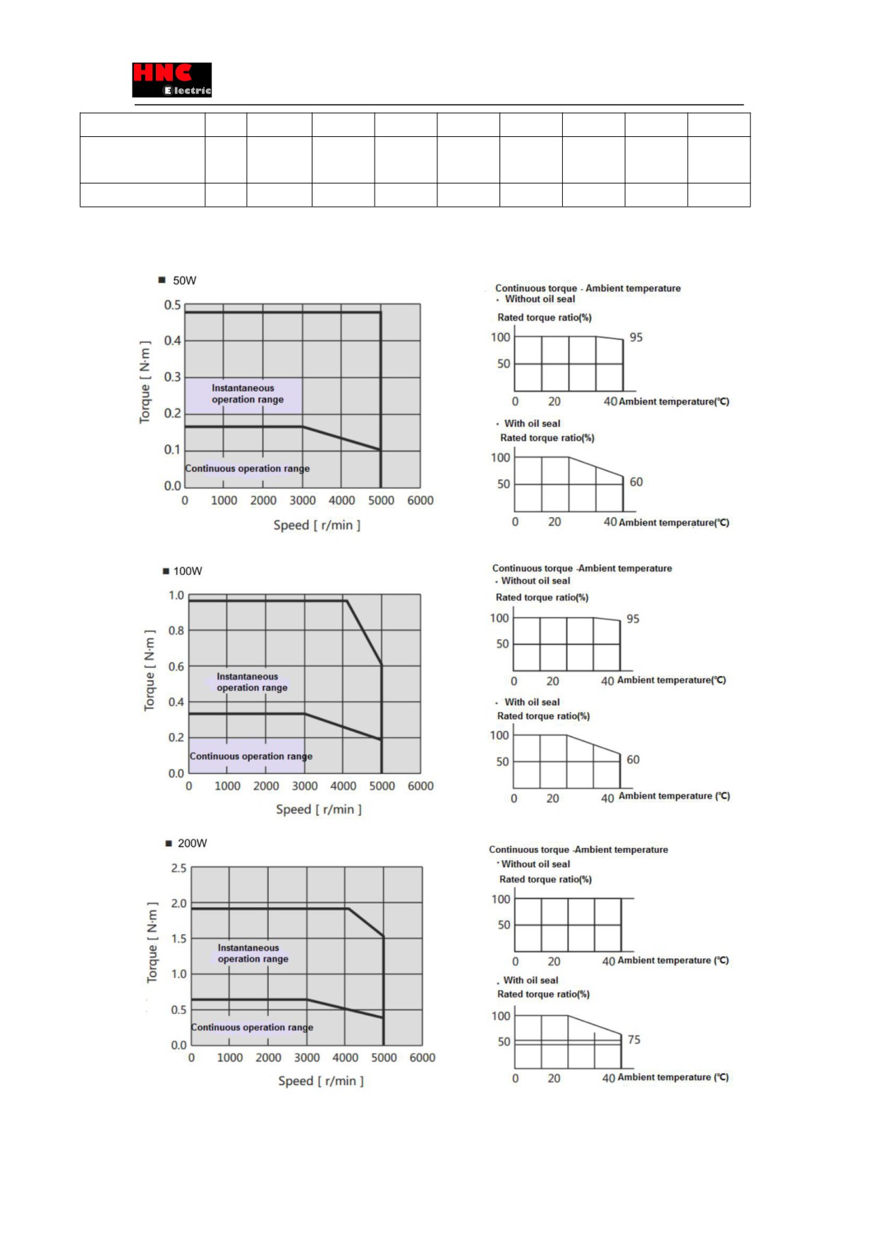
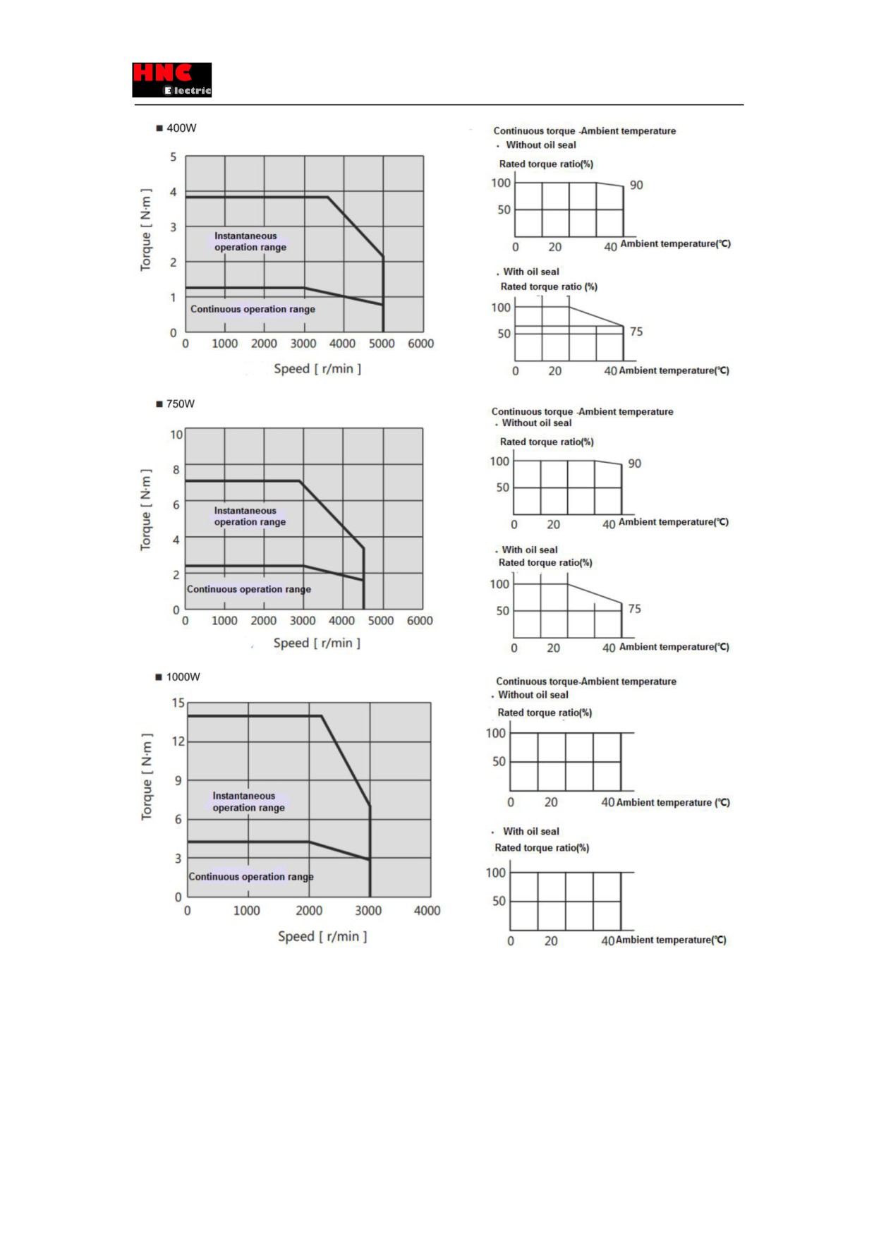
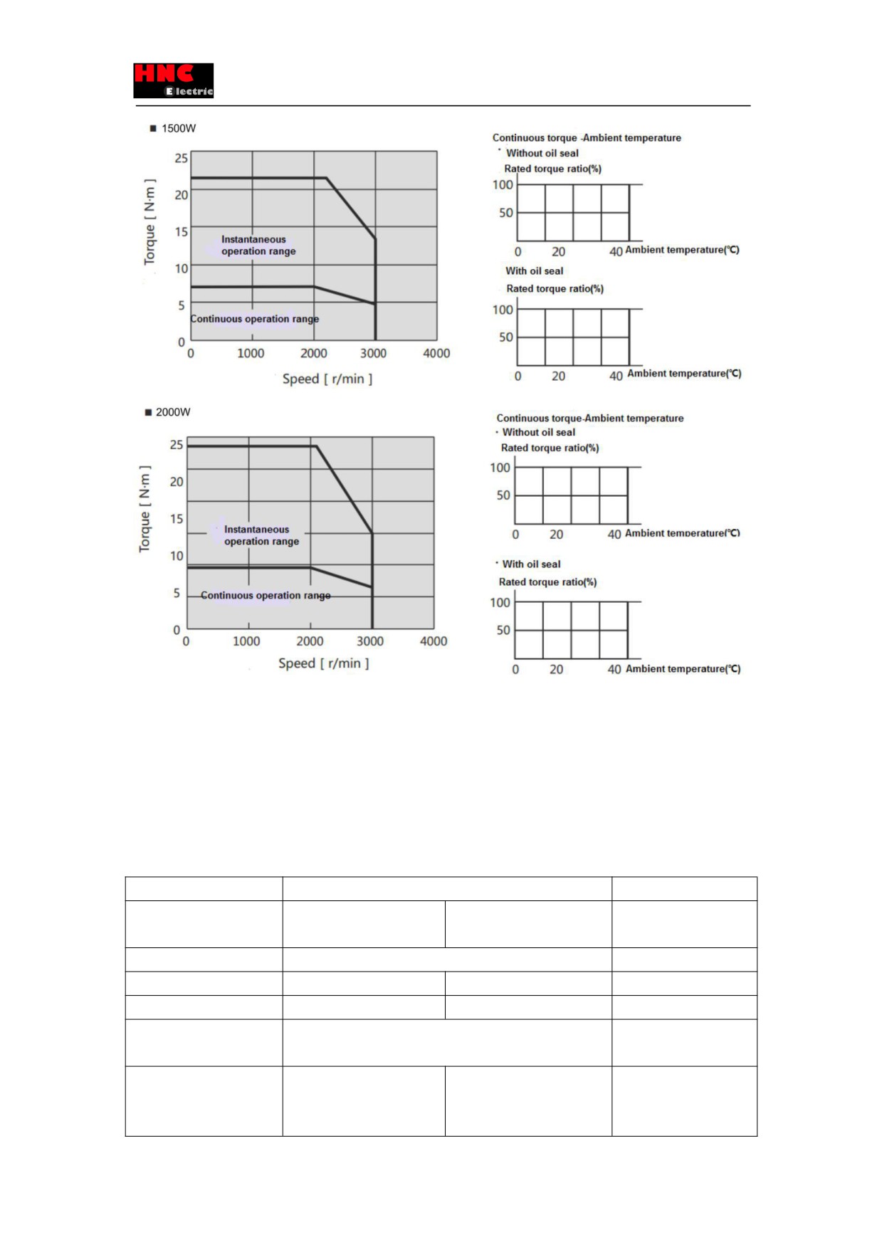
2.2.3 N-T characteristics
Figure 2.2.2 N-T characteristics
20
21
2.2.4 Encoder specifications
Table 2.2.3 Encoder specifications
Items
Description
Remarks
Motor Model Name
SE□□-2-□□□□□□-I1(17
SE□□-2-□□□□□□-A1(17
-
bit)
bit)
Power supply voltage VCC
DC 4.5V~5.5V
Ripple voltage 5% or less
External power supply BAT
-
DC 2.4V~5.5V
-
External capacitor CAP
-
DC 2.4V~5.5V
-
Current consumption
160mA(Typ.)
Inrush current are
excluded.
State of low power
-
Typ 10µA
The battery voltage is
consumption
3.6V at motor stop at
room temperature
22
Single revolution resolution
Absolute 131,072(17bit)
-
Multi-revolution count
-
65,536
Count
-
Maximum speed
6,000 r/min
-
Input/ Output form
Differential transmission
-
Count-up direction
CCW
-
Table 2.2.4
Item
Description
Motor Model Name
SE□□-2-□□□□□□-I1(17 bit)
SE□□-2-□□□□□□□-A1(17bit)
Transmission method
Half-duplex asynchronous serial communication
Communication speed
2.5Mbps
Table 2.2.5
Item
Description
Working temperature
0~85℃
Resistance to external magnetic field
±2mT(20G) or less
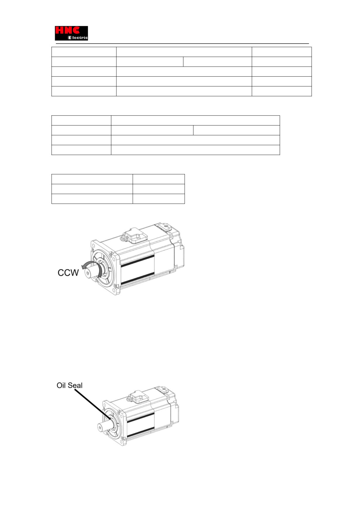
Note 1) Up-counting direction
※Look from the front flange, rotate as counterclockwise, that is CCW.
[Note]
※When the motor rotates under 180 degree, single revolution accuracy decreases.
※When use the motor with brake, please follow the brake voltage specified in the manual.
※When the brake voltage is under 12V or use under the reverse polarity, single revolution accuracy decreases.
2.2.5 About oil seal
Please use oil seal to prevent the entry of oil into the servo motor via the output shaft when using motor with gear box. All the
SV-E3 series motors are installed with the oil seal.
23
3. Installation and size of servo motor and drive
3.1 Installation environment conditions
About the environmental conditions, make sure to follow the company’s instructions. If you need to use the product outside the
scope of the environmental conditions, please consult HNC ELECTRIC Corporation in advance.
1
Keep it away from the direct sunlight.
2
Drive must be installed in the cabinet.
3
Keep it away from the water, oil (cutting oil, oil mist) and moisture.
4
Do not install the equipment under the conditions with water, corrosive and flammable gas.
5
Free from the dust, iron powder, cutting powder and so on.
6
Keep it away from the area with high temperature, excessive vibration and shock.
3.2 Dustproof and waterproof
The servo drive is non-waterproof structure. Protection level of motor (excluding the connector) is IP65 according to IEC
34-5(International Electrotechnical Commission).
3.3 Installation method and space
Impact & load
①The impact that the motor can stand should be less than 200m/s2(20G). Don’t apply excessive impact load to the motor
during transporting, installing and disassembling. And do not hold encoder, cable and connector to transport the motor.
②The pull claw device must be used when removing the belt pulley and coupler from the motor
Combination with mechanical system
①The motor specification in the user manual has specified the permissible load to the motor shaft. Exceeding the permissible
load will shorten the shaft life and cause damage to the shaft. Please use coupling which could fully absorb eccentric load.
②The stress on the encoder cable should be less than 6kgf during assembling.
③The bending radius of power cable and encoder cable should be R20mm and more.
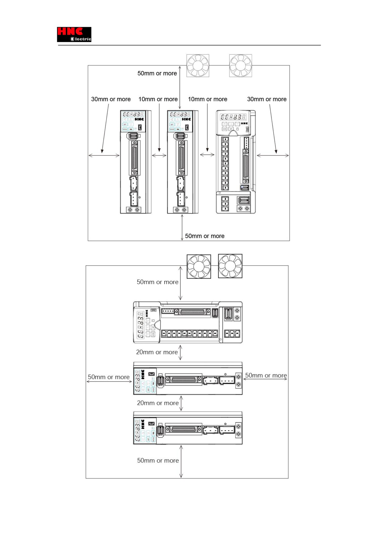
Installation direction and clearance of drives
Leave sufficient space around the drive to ensure the heat dissipation and convection in the cabinet when installing the drive.
24
25
●Install the drives in the vertical direction. Please use two M5 screws to fix the drive, master drive and slave drive
respectively which is less than 800W Please use three M5 screws to fix the drive and master drive respectively which is
more than 1kW.
●In order to ensure that surrounding temperature between internal boards is not more than 55℃, cooling fan or cooler need
to be installed to reduce the temperature, when the drives are installed in the sealed cabinet.
●The temperature on the surface of cooling plate would be 30℃ higher than the surrounding temperature.
●Use heat-resistant material for the wiring and isolate wiring from the machine and other cables which are easily affected by
the temperature.
●The service life of servo drive depends on the temperature around the electrolytic capacitor. When the electrolytic capacitor
is close to the service life, the static capacity will decrease and internal resistance will increase. Consequently, it will lead to
overvoltage alarm, malfunction caused by noise and components damage. The service life of electrolytic capacitor is approx. 5
to 6 years under the condition「average annual temperature 30℃, load rate 80% and operation of less than 20 hours a day on
average」
Additional instructions
①The motor shaft is covered with anti-rust oil before leaving factory. Please have the antirust treatment again to the shaft to
prevent it from rust when installing load.
②Never disassemble the encoder or motor.
③The GND of 24VDC input and the grounding cable of device can be connected to each other.
※Please use the same power supply for control voltage(24V and GND) and upper control device.
④Do not remove or maintain the encoder battery until the main power supply is switched OFF.
⑤After switching off the main power supply, please note that there is residual voltage of approx. 30 seconds on the power
components.
⑥Do not replace the fuse.
⑦The servo drives of more than 750W are installed with a cooling fan on the right side. Do not touch or block the ventilation
ports of servo drive
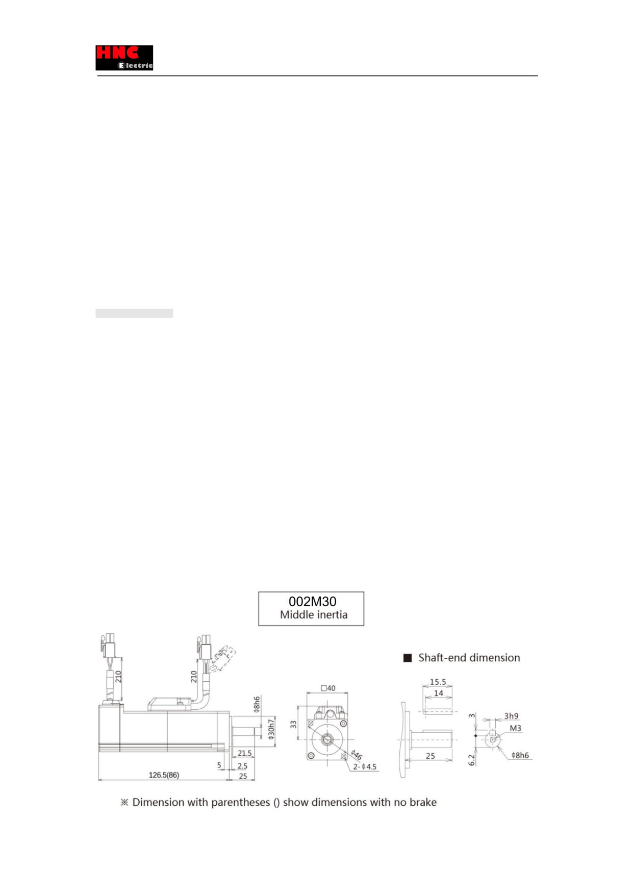
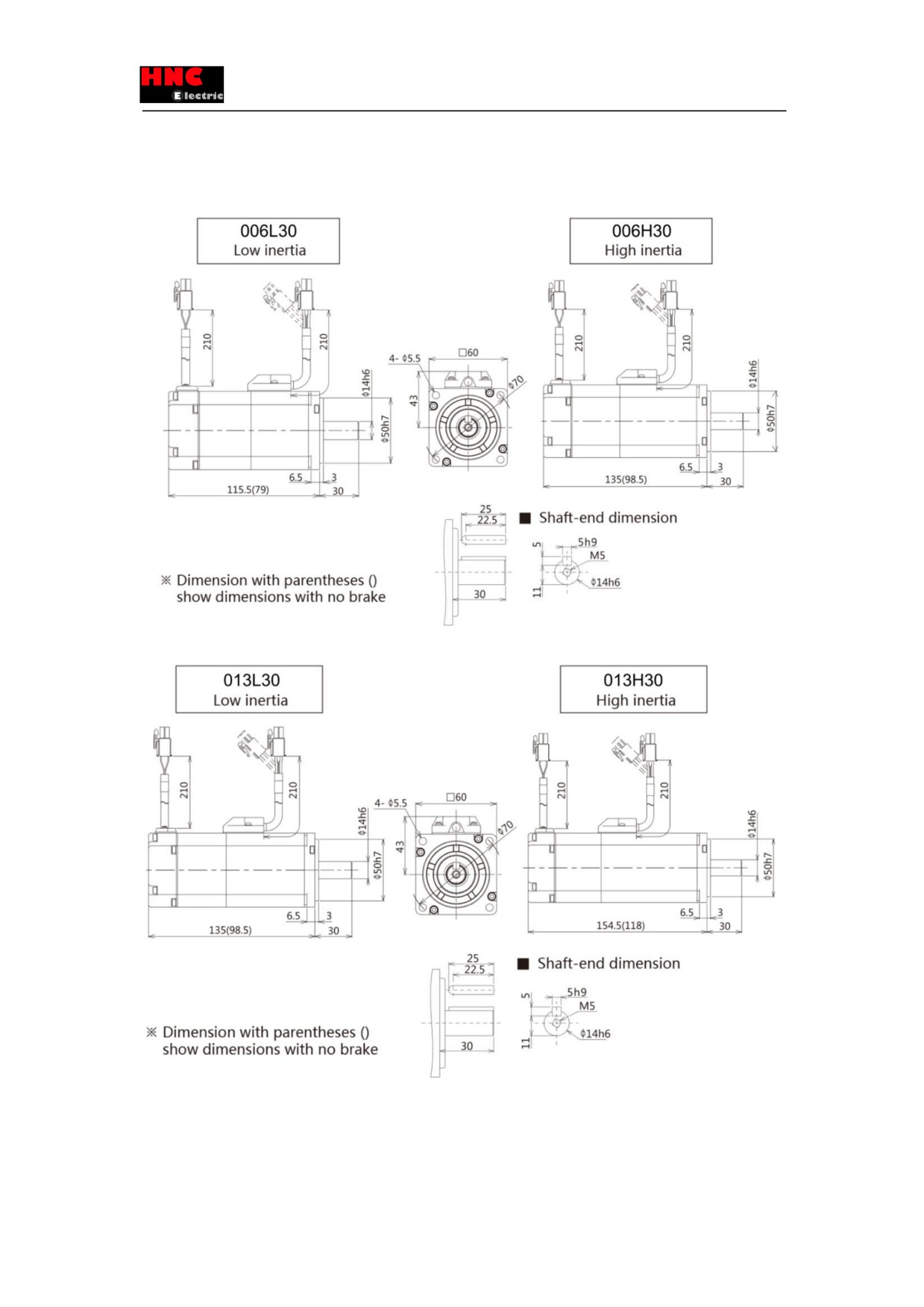
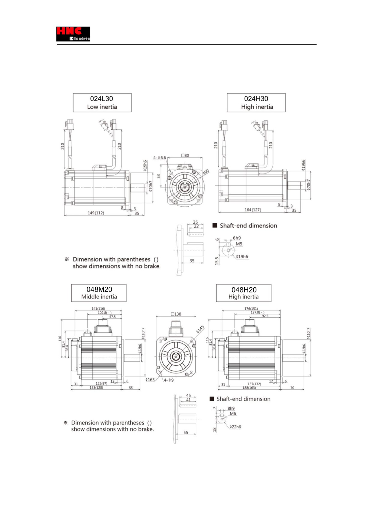
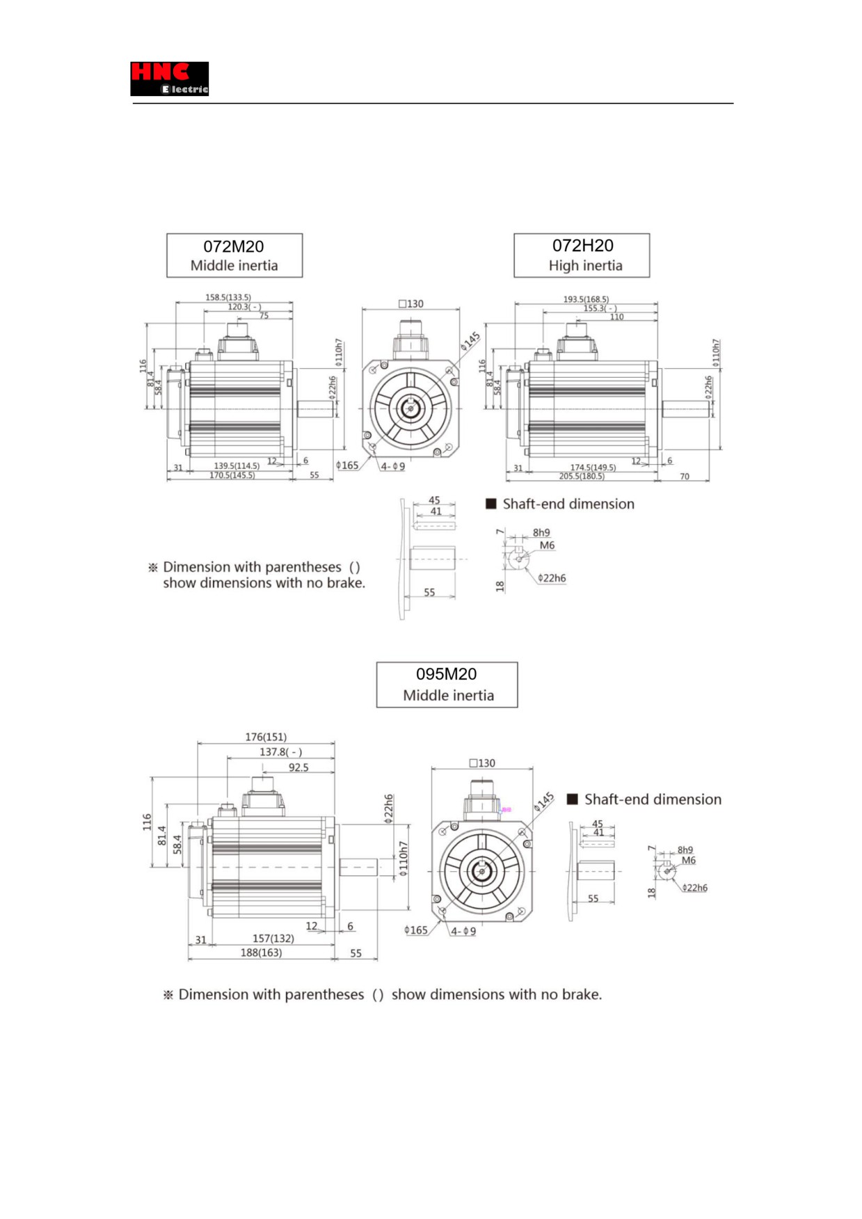
3.4 Dimensions of servo motor
26
27
28
29
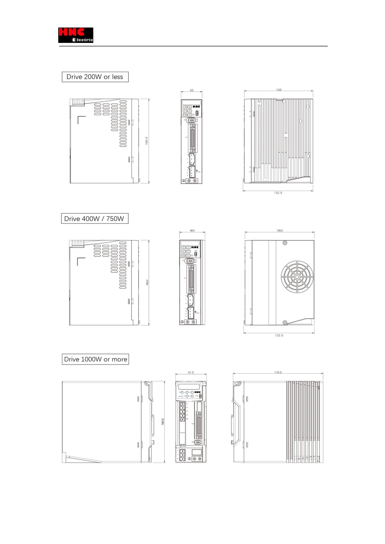
3.5 Dimensions of servo drive (Same dimensions for SV-E3)
30
4. Wiring explanation for servo motor and drive
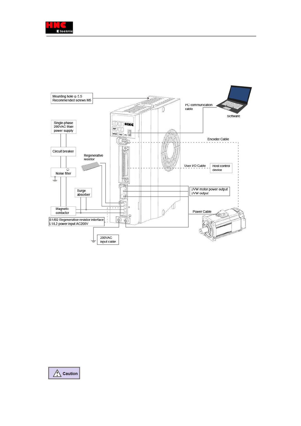
4.1 Wiring diagram
4.1.1 Wiring diagram
[Points for correct wiring]
※ 24VDC and 200VAC input (main circuit) power supply should be wired from the same 200VAC main power supply.
※ Do not access switch between 24VDC power supply and drive. If you need switch, put it on the 200VAC cable of 24VDC
input power supply.
※ A twisted-pair shielded cable should be used when I/O cable length is over 50cm.
※ The encoder cable should be less than 20m.
31
① Please note that there is high voltage in the solid line of wiring diagram when wiring and using.
② The broken lines in the wiring diagram indicates the non-dangerous voltage circuit.
4.1.2 Connection of servo drive and motor
Items
Description
Peripheral device
Conform to European EC Directive. Select the device which meets corresponding standards
and install them in accordance with User’s Manual.
Installation environment
Install the servo drive to the environment which conform to Pollution degree 2 or 1 of
IEC60664-1.
Power supply 1: 200~
This product can be used under the conditions that conform to IEC60664-1 and overvoltage
230VAC (main circuit)
category Ⅱ.
Power supply 2: 24VDC
The specification of 24VDC external power supply should satisfy the following conditions.
♦control power supply of drive
Using SELV power supply(※) and power less than 150W. This is the CE corresponding
♦I/O power supply
conditions.
♦Power supply for brake
※SELV: safety extra low voltage
release
(Reinforced insulation is needed for safety extra low voltage, non-dangerous voltage and
dangerous voltage.)
Wiring
Please use withstand voltage cables which are equivalent to AWG18/600V or AWG14/600V
for motor power cable, encoder cable, AC220 input cable, FG cable and main circuit power
distribution cable under multi-axis drive structure respectively when drives are less than
750W or more than 1kW .
Breaker
Switch off the power supply to protect power cord when overcurrent occurs.
Make sure to use the breaker between power supply and interference filter that conforms to
IEC specification and UL recognition in accordance with the User manual.
Please use the breaker with leakage function recommended by HCFA in order to meet EMC
standards.
Noise filter
To prevent the outside interference from power cables.
Please use the interference filter recommended by HCFA in order to meet EMC standards.
Magnetic contactor
Switch main power supply (ON/OFF). And use it after installing a surge absorber.
Surge absorber
Please use the surge absorber recommended by HCFA in order to meet EMC standards.
Interference filter for signal
Please use the interference filter recommended by HCFA in order to meet EMC standards.
cable / ferrite filter
Regenerative resistor
This product is not equipped with regenerative resistor.
The external regenerative resistor is necessary when the internal capacitor cannot absorb
more regenerative power. Confirm the regenerative status on the panel. When the
regenerative voltage alarm is ON, a regenerative resistor is needed.
For the reference specification of regenerative resistor, please refer to user manual.
Use a built-in thermostat and set overheat protect circuit.
Grounding
This product belongs to Class 1 and need grounding protection.
Using protection grounding terminal. Grounding should be executed by the case and cabinet
that conforms to EMC.
The following symbol indicates the protection grounding terminal.
32
4.2 Drive connector and pins arrangement
4.2.1 Drive connector terminal
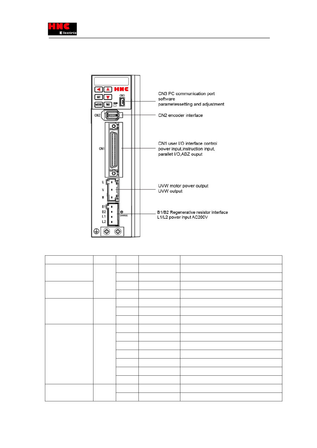
Figure 4.2.1 750W or less Drive connector terminal
Table 4.2.1 Terminal arrangement of drive connector/ SV-E3P 750W or less
Name
Symbol
Pin No.
Signal name
Contents
Regenerative
B1/B2/L1
1
B1
P interface of regenerative resistor
resistance connection
/L2
2
B2
N interface of regenerative resistor
Single-phase 200VAC
3
L
Primary Power 1
input
4
N
Primary Power 2
Motor power output
U/V/W
1
U
Motor power U phase output
2
V
Motor power V phase output
3
W
Motor power W phase output
Encoder
CN2
1
VCC
Encoder power supply 5V output
2
GND
Signal grounding
3
NC
-
4
NC
-
5
+D
Encoder signal: data input/output
6
-D
Encoder signal: data input/output
-
FG
Connect SHIELD to the connector housing
PC communication
CN3
1
VBUS
USB power supply
2
D-
USB data-
33
3
D+
USB data+
4
NC
-
5
GND
USB signal grounding
External fan
CN14
1
24V
24V for external fan
2
G24
GND for external fan
3
NC
-
User I/O
CN1
Refer to “Chapter 8
Operation”
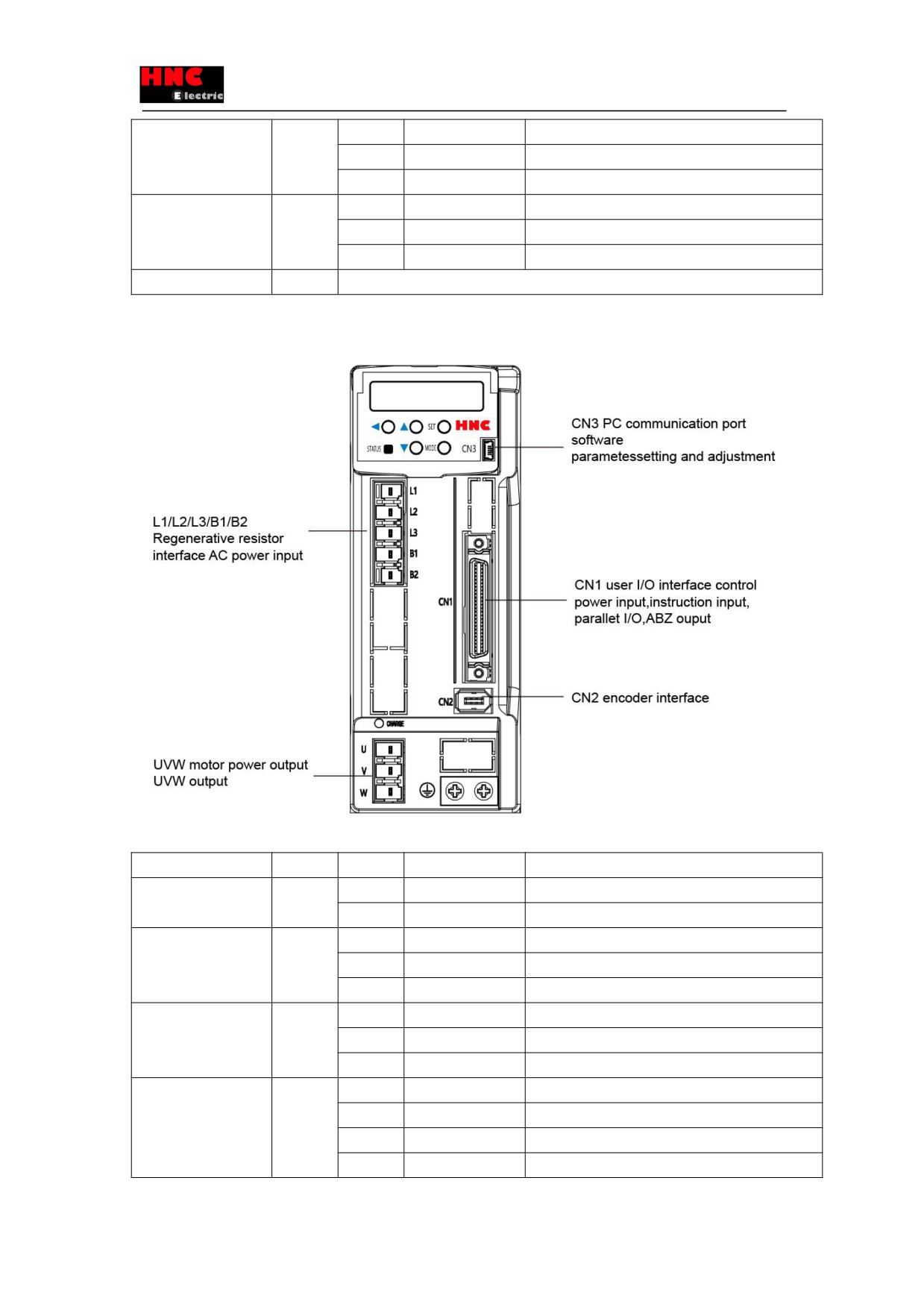
Figure 4.2.2 1KW or more Drive connector terminal
Table 4.2.2 Terminal arrangement of drive connector/ SV-E3P1KW or more
Name
Symbol
Pin No.
Signal name
Contents
Regenerative
B1/B2
1
B1
P interface of regenerative resistor
resistance connection
2
B2
N interface of regenerative resistor
Three-phase 200VAC
L1/L2/L3
1
L1
Primary power 1
input
2
L2
Primary power 2
3
L3
Primary power 3
Motor power output
U/V/W
1
U
Motor power U phase output
2
V
Motor power V phase output
3
W
Motor power W phase output
Encoder
CN2
1
VCC
Encoder power supply 5V output
2
GND
Signal grounding
3
NC
-
4
NC
-
34
5
+D
Encoder signal: data input/output
6
-D
Encoder signal: data input/output
-
FG
Connect SHIELD to the connector housing
PC communication
CN3
1
VBUS
USB power supply
2
D-
USB data-
3
D+
USB data+
4
NC
-
5
GND
USB signal grounding
User I/O
CN1
Refer to “Chapter 8 Operation”
4.3 Terminal arrangement and wiring color of motor connector
4.3.1 Motor connector and pins arrangement (750W or less)
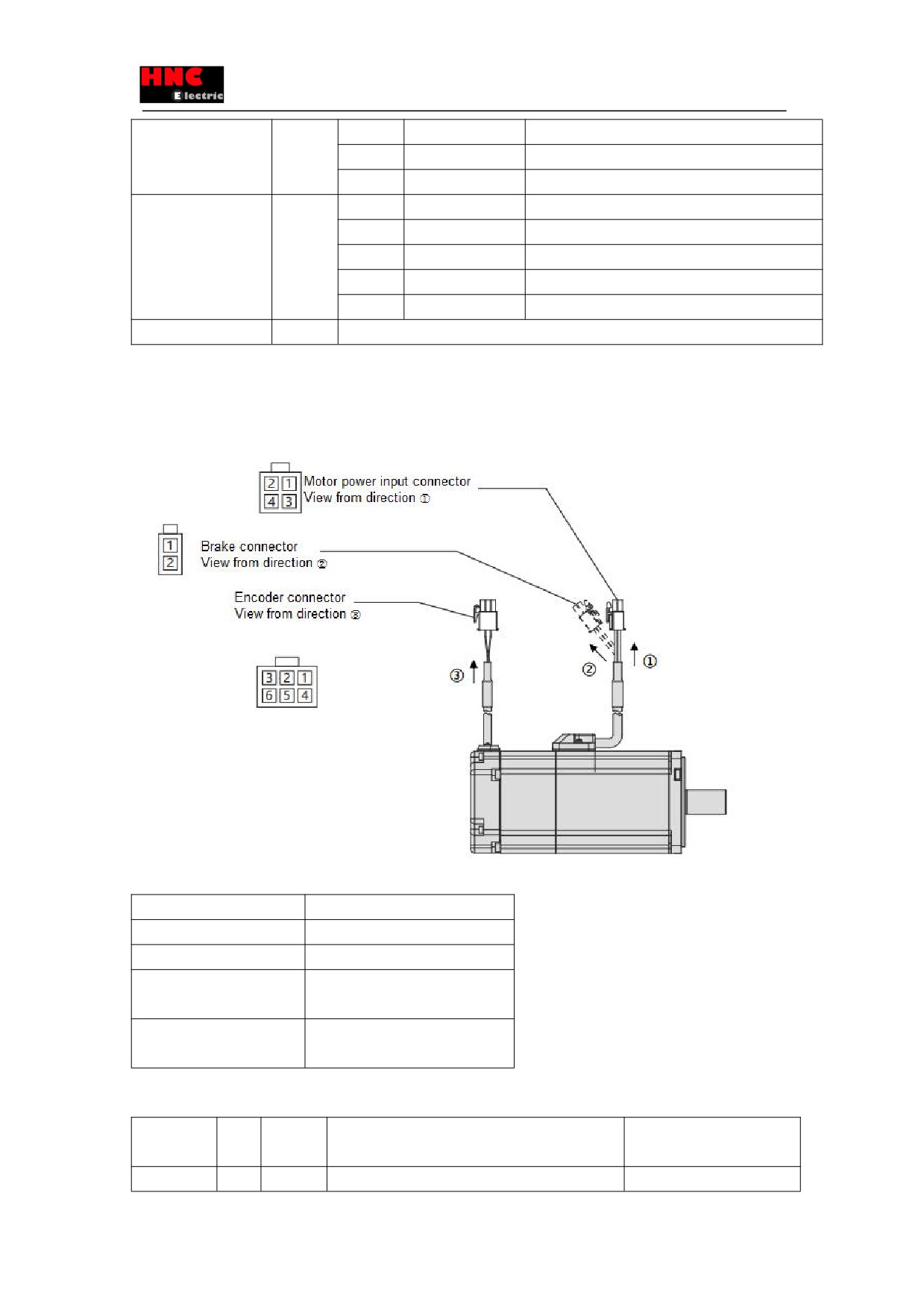
Figure: 4.3.1 Motor connector and pins arrangement
Table 4.3.1 Cable list (For motor of 750W or less)
Name
Cable
Motor power input
AWG18
Brakenote1
AWG22
Encoder (Incremental)
Power supply:AWG22
Signal:AWG24
Encoder (Absolute)
Power supply:AWG22
Signal:AWG24
Note 1 For the motor with brake
Table 4.3.2 For the motor of 750W or less
Name
Pin
Signal
Contents
Wiring color
No.
name
Motor power
1
U
Motor power U phase
Red
35
input
2
V
Motor power V phase
White
3
W
Motor power W phase
Black
4
FG
Motor housing grounding
Green
Brake
1
BRK+
Brake power supply 24VDC
Yellow
(※ 1)
2
BRK-
Brake power supply GND
Blue
Encoder(incr
1
-
NC
-
emental)
2
+D
Serial communication data
+ data
White (red point)
3
-D
Serial communication data
- data
White (black point)
4
VCC
Encoder power supply 5V
Orange (red point)
5
GND
Signal ground
Orange (black point)
6
SHIELD
Shielded wires
Black
Encoder(Abs
1
BAT
External battery (※ 2)
Yellow (black point)
olute)
2
+D
Serial communication data
+ data
White (red point)
3
-D
Serial communication data
- data
White (black point)
4
VCC
Encoder power supply 5V
Orange (red point)
5
GND
Signal ground
Orange (black point)
6
SHIELD
Shielded wires
Black
※1 For motor with brake.
※2 External capacitor and battery are taking GND as the reference potential.
4.3.2 Motor connector and pins arrangement (1kW or more)
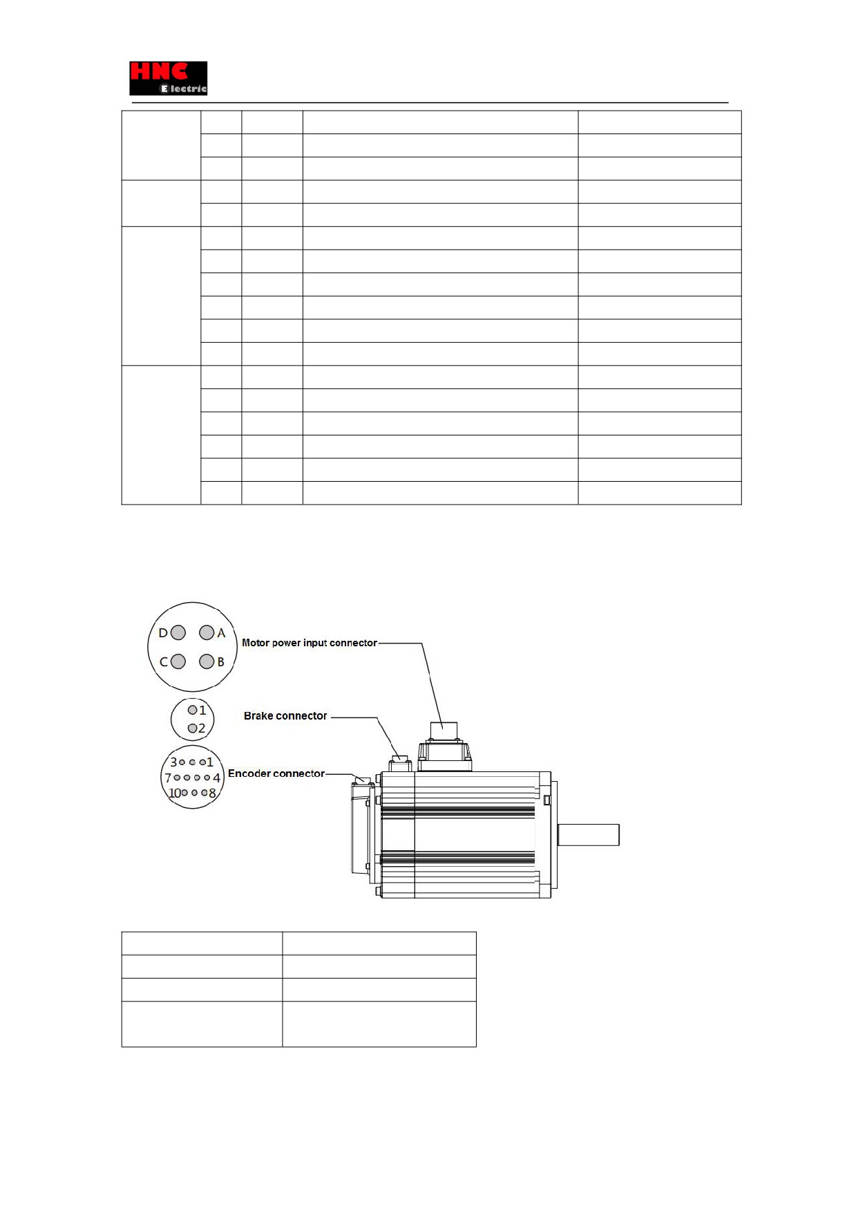
Figure 4.3.2 Motor connector and pins arrangement (1kW or more)
Table 4.3.3 Cable list ( for motor of 1kW or more)
Name
Cable
Motor power input
AWG14
Brakenote1
AWG18
Encoder (Incremental)
Power supply:AWG22
Signal:AWG24
Note 1 For the motor with brake
Table 4.3.4 For the motor of 1kW or more
36
Name
Pin
Signal
Contents
Remark
No.
name
Motor power
A
U
Motor power U phase
input
B
V
Motor power V phase
C
W
Motor power W phase
D
FG
Motor housing grounding
Brake
1
BRK1
Brake power supply 24VDC
(※ 1)
2
BRK2
Brake power supply GND
Encoder(incr
1
VCC
Encoder power supply 5V output
emental)
2
GND
Signal ground
3
-
NC
4
-
NC
5
+D
Serial communication data
+ data
6
-D
Serial communication data
- data
7
-
NC
8
-
NC
9
-
NC
10
SHIELD
Shielded wires
Encoder(Abs
1
VCC
Encoder power supply 5V output
olute)
2
GND
Signal ground
3
CAP
External capacitor (※2)
4
BAT
External battery (※2)
5
+D
Serial communication data
+ data
6
-D
Serial communication data
- data
7
IC
Internal connection (※ 3)
8
IC
Internal connection (※ 3)
9
GND
Signal ground
10
-
NC
※1 For motor with brake.
※2 External capacitor and battery are taking GND as the reference potential.
※3 Internal connection (IC) has been connected internally. Do not connect it with any other wires.
4.4 RS-485 communication wiring description
The wiring between the drives and setting method of communication address are shown below. When using multi-station
communication(the upper controller is wired with one servo drive), the parameters of multiple servo drives can be changed
and the waveform of position deviation and rotation speed can be monitored by the upper controller.
The communication condition shown below.
Table 4.4.1
Communication
Electrical specifications
EIA485
Communication method
Asynchronous serial
communication(half-duplex)
37
Communication speed
57.6 kbps
Data bit
8 bit
Peer bit
None
Stop bit
1 bit
Alarm detection
CRC16-CCITT
Transmission data
8 bit binary
Data length
35 bytes or less
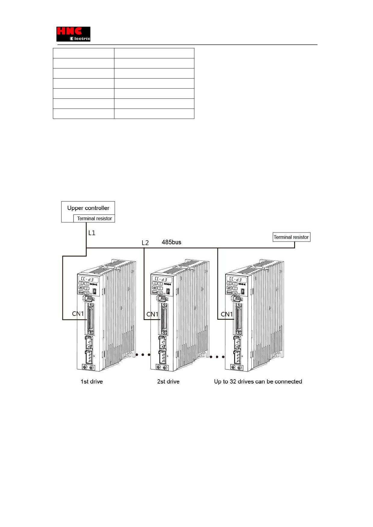
L1= 5m(max)
The wiring length between the upper controller and drive CN1 should be 5m or less.
L2=250mm(max)
The wiring length between each drives CN1 should be 250mm or less.
Terminal resistance
Connect the terminal resistor between 43pin and 44pin of CN1 to the last drive and to the upper controller.
Figure 4.4.1 Multi-station connection example
The wiring between the drives are shown as above. And daisy-chained connection should be performed between the drive
connector CN1 and the upper controller.
[Communication address setting]
When using multi-station communication, set the different communication address for each drive according to the following
steps. There are two setting methods: by set panel and dedicated software.
Input 24V control power supply after wiring, then operate as the following steps For wiring, refer to section 4.1[Wiring
diagram].
38
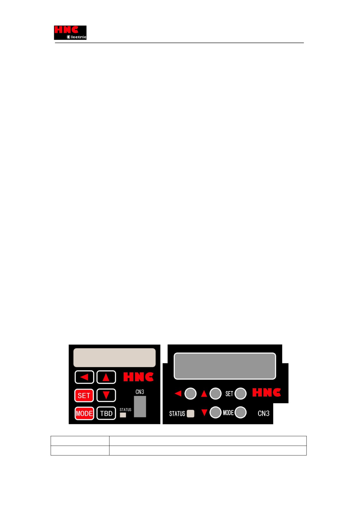
[Setting method by set panel]
①Press the MODE button three times from the initial display status. The leftmost display on the LCD (6 digits) is [P] to come to
the parameter setting mode. There is 3 digits, the point(.) and 1 digit on the right side of [P]. And the rightmost display is blank
or [r]. The parameter number is represented by 3 digits, the point(.) and 1 digit.
②Press the UP/DOWN and SHIFT button, when [P004.0r] shows, press SET button to display the current setting value. The
initial value is [1].
③Press the UP/DOWN and SHIFT button and input the expected communication address. Setting range is from 1 to 32.
④Press the SET button to RAM, the indicator changes from flicker to lit.
⑤Press the MODE button three times to display [SAVE_P].
⑥ Press the SET button, the [P] in [SAVE_P] flicker. When the parameter is stored in the EEPROM normally, [nr_End]
displays.
⑦Notes: Cut off the power supply to the servo drive(Note1). Before restart the power supply, the servo drive operates as the
former communication address.
⑧Set the communication address to the other drive as the same way described from ① to ⑦. When the single-axis drive are
used in parallel, please set the communication address by the set panel of the servo drive.
5. Panel display and operation
5.1 Overview
The functions of operation panel are as follows:
a) Status display (Status display mode)
b) Alarm display (Alarm display mode)
c) Parameter setting (Parameter setting mode)
d) Auto tuning (Auto tuning mode)
e) Parameter saving (parameter saving mode)
f) Auxiliary functions (JOG function mode, parameter clearing mode, encoder clearing mode)
5.2 Part names
Table 5.2.1 Set panel for drive
Items
Description
MODE
Change operation mode and parameters.
39