SERVO DRIVE SV-E3 SERIES. INSTRUCTION MANUAL (v1.5) - page 1
SERVO DRIVE
SV-E3 SERIES INSTRUCTION MANUAL
Preface
3
1. About the instruction manual
3
2. Confirm the following items before unpacking
3
3. Safety precautions
3
1. Product introduction and model selection
7
1.1 Introduction of nameplate and model name (For servo motor and drive)
7
1.2 Parts name of servo motor and drive
8
1.3 Model name of servo drive and motor
9
1.4 Model selection of peripheral braking resistor
10
1.5 Selection of cables and connector accessories for HNC ELECTRIC products... 10
2. Product specifications
11
2.1 Servo drive specifications
11
2.2 Motor specifications
16
3. Installation and size of servo motor and drive
24
3.1 Installation environment conditions
24
3.2 Dustproof and waterproof
24
3.3 Installation method and space
24
3.4 Dimensions of servo motor
26
3.5 Dimensions of servo drive
30
4. Wiring explanation for servo motor and drive
31
4.1 Wiring diagram
31
4.2 Drive connector and pins arrangement
33
4.3 Terminal arrangement and wiring color of motor connector
35
4.4 RS-485 communication wiring description
37
5. Panel display and operation
39
5.1 Overview
39
5.2 Part names
39
5.3 Operation mode change
40
5.4 Status display mode
42
5.5 Alarm display mode
48
5.6 Parameter setting mode
50
5.7 Auto tuning mode
51
5.8 Parameter saving mode
53
5.9 Auxiliary function
54
6. Parameter Description
57
6.1 Parameter list
57
6.2 Parameter list for point table
83
7. Timing chart
83
7.1 Power ON
83
7.2 Servo OFF→ON
84
1
7.3 Servo stop
85
7.4 At occurrence of alarm
86
7.5 Alarm reset
88
8. Operation
89
8.1 Preface
89
8.2 Position control mode (Pulse position command input)
92
8.3 Speed control mode (Analog speed command input)
103
8.4 Speed control mode (Internal speed command)
108
8.5 Torque control mode (Analog torque command input)
112
8.6 Position control mode(Internal position command)
117
8.7 Description of User I/O connector (CN1) terminal arrangements
118
8.8 Adjustment
126
8.9 Home position return
132
9. Troubleshooting and countermeasures
154
9.1 Alarm display
154
9.2 Alarm handling and alarm reset
154
9.3 Troubleshooting
158
Appendix
161
Appendix 1 Recommended wire/cable
161
Appendix 2 SV-E3 positioner function
161
Appendix 3 SV-E3 special I/O setting
167
Appendix 4 Servo drive power connector (L1/ L2/B1/B2, U/ V/ W)wiring
169
Appendix 5 SV-E3 series absolute system description
170
Thank you for purchasing the HNC ELECTRIC products.
This Instruction Manual provides instructions for advanced use of the SV-E3 series servo motors.
●Before use, read this manual and manuals of relevant products fully to acquire proficiency in handling and operating the
product.
●Please read the safety precautions before using.
●Store this manual in a safe place so that you can take it out and read it whenever necessary.
●As for products under development, specifications are subject to change without notice.
2
Preface
Incorrect operation and handling, couldn’t have a full display of the various performance that designed, and may cause
hazardous conditions and shorten the service life. Please operate the product correctly before you have read through the
instruction manual correctly.
1. About the instruction manual
1 We make an effort to perfect this instruction manual, but if you have found some mistakes or uncertain points, please
contact HNC ELECTRIC at any time.
2 Please note the following items on the instruction manual
●Danger exists as it’s the high-voltage device.
●There are some residual voltage on the terminals or the units after power OFF and it is dangerous.
●High temperature locally
●Disassembling is prohibited.
3 The product specifications and functions may change and increase, as the product performance upgraded. They are subject
to change without notice.
4 Plan to obtain the Certificate of safety specification for the product’s device, please consult our sales representative.
5
To extend the service life of motor and drive, it is necessary to use it under the correct conditions. Please follow the
instruction manual for details.
6 The latest information should be recorded in the instruction manual and manual will be updated accordingly. If you need the
latest version, please contact the HNC ELECTRIC distributor.
7 Without the approval of company, it is forbidden to reprint some or all of the instruction manual.
2. Confirm the following items before unpacking.
●Check if the products are the ones you ordered.
●Check if there are some damage to the products during transportation.
●Any questions, please contact the HNC ELECTRIC distributor.
3. Safety precautions
Please pay attention to the flowing safety precautions anywhere and any time during acceptance inspection, installation,
wiring, operation and maintenance.
Indicates that incorrect handling may result in death or severe injury.
Indicates that incorrect handling may result in medium or slight personal injury or physical damage.
Indicates “Prohibitions”(Indicates what must not be done.)
Indicates “Forced”.(Indicates what must be done.)
Installing and wiring
Do not connect the motor to the commercial power.
To prevent fire or malfunction.
Do not place the combustibles around the servo motor and drive.
To prevent fire.
Be sure to protect the drives through the case, and leave specified
To prevent electric shock, fire or
clearances between the case or other equipment and the drive.
malfunction.
3
Install it at the place free from excessive dust and dirt, water and oil mist
To prevent electric shock, fire ,
malfunction or damage
Install the equipment to incombustibles, such as metal.
To prevent fire.
Any person who is involved in wiring and inspection should be fully
To prevent electric shock.
competent to do the work.
FG terminal of motor and drive must be grounded.
To prevent electric shock.
Perform the wiring correctly after cut off the breaker.
To prevent electric shock, injury,
malfunction or damage
Have the insulation processing when connecting cables.
To prevent electric shock, fire or
malfunction.
Operation and running
During operation, never touch the internal parts of the drive.
To prevent burns or electric shock.
The cables should not be damaged, stressed loaded, or pinched.
To prevent electric shock, malfunction
or damage.
During operation, never touch the rotating parts of the servo motor.
To prevent injury.
Do not install the equipment under the conditions with water, corrosive
To prevent fire.
and flammable gas.
Do not use it at the location with great vibration and shock.
To prevent electric shock, injury or
fire.
Do not use the servo motor with its cable soaked in oil or water.
To prevent electric shock, malfunction
or damage
Operate the switches and wiring with dry hand.
To prevent electric shock, injury or
fire.
Do not touch the keyway directly when using the motor with shaft-end
To prevent injury.
keyway
Do not touch the motor and drive heat sink, as they are very hot.
To prevent burns or parts damaged.
Do not drive the motor by external drive.
To prevent fire.
Other safety instructions
Confirm the equipment’s safety after the earthquake happens.
To prevent electric shock, injury or
fire.
Installing and setting correctly to prevent the fire and personal injury when
To prevent injury, electric shock, fire,
earthquake happens.
malfunction or damage.
Provide an external emergency stop circuit to ensure that operation can
To prevent injury, electric shock, fire,
be stopped and power switched off immediately.
malfunction or damage.
Before wiring or inspection, turn off the power and wait for 5 minutes or
To prevent electric shock.
more.
Installing and wiring
Please follow the specified combination of the motor and drive.
To prevent fire or malfunction.
Do not touch the terminals of connector directly.
To prevent electric shock or
malfunction.
Do not block intake and prevent the foreign matters from entering into the
To prevent electric shock or fire.
4
motor and drive.
Fix the motor and have the test run away from the mechanical system.
To prevent injury.
After confirming the operation, the motor can be securely mounted to
mechanical system.
The servo motor must be installed in the specified direction.
To prevent injury or malfunction.
Install the equipment correctly in accordance with its weight and rated
To prevent injury or malfunction.
output.
Operation and running
Do not climb or stand on servo equipment. Do not put heavy objects on
To prevent electric shock, injury, fault
equipment.
or damage.
The parameter settings must not be changed excessively. Operation will
To prevent injury.
be instable.
When power is restored after an instantaneous power failure, keep away
To prevent injury.
from the machine because the machine may be restarted suddenly
(design the machine so that it is secured against hazard if restarted).
Keep it away from the direct sunlight.
To prevent malfunction.
Do not put strong impact on the motor, drive and motor shaft.
To prevent malfunction.
The electromagnetic brake on the servo motor is designed to hold the
To prevent injury or malfunction.
servo motor shaft and should not be used for ordinary braking.
Do not install or operate a faulty servo motor or drive.
To prevent injury, electric shock or fire
Check the power specification.
To prevent fault.
The electromagnetic brake may not hold the servo motor shaft. To ensure
To prevent injury.
safety, install a stopper on the machine side.
A sudden restart is made if an alarm is reset with the run signal on.
To prevent injury.
Connect the relay for emergency stop and for brake in series.
To prevent injury or malfunction.
Transportation and storage
Do not subject the equipment to the place with rain, waterdrop, poisonous
To prevent malfunction.
gases or liquids.
Do not carry the servo motor by the cables, shaft or encoder during
To prevent injury or malfunction.
transportation.
Do not drop or dump the motor during transportation and installation.
To prevent injury or malfunction.
Store the unit in a place in accordance with the instruction manual.
To prevent malfunction.
Other safety instructions
Please dispose the battery according to your local laws and regulations.
When disposing of the product, handle it as industrial waste.
Maintenance and inspection
Do not disassemble and/or repair the equipment on customer side.
To prevent malfunction.
Do not turn on or switch off the main power frequently.
To prevent malfunction.
Do not touch the servo drive heat sink, regenerative resistor, servo motor
To prevent burns or electric shock.
etc. Their temperatures may be high while power is on or for some time
after power-off.
When the drive become faulty, switch off the control circuit and main
To prevent fire.
power.
5
If the servo motor is to be stored for a long time, switch off the power.
To prevent mis-operation and injury.
Warranty period
The term of warranty for the product is 18 months from the date of manufacture. It’s exceptional to brake motors as they are
warranted when acceleration / deceleration times is not beyond the specified service life.
Warranty coverage
This warranty applies only when the condition, method, environment, etc. of use are in compliance with the terms and
conditions and instructions that are stated in the instruction manual and user manual for the Product.
However, even during warranty period, the repair cost will be charged on customer in the following cases.
1) A failure caused by improper storing or handling, repair and modification.
2) A failure caused by the parts which have dropped down or damaged during transportation
3) A failure caused when the products have been used beyond the product specification
4) A failure caused by external factors such as inevitable accidents, including but not limited to fire, earthquake, lightning
stroke, windstorm disaster, flood, salt damage, abnormal fluctuation of voltage and other natural disaster.
5) A failure caused by the intrusion of water, oil, metal and other foreign matters.
The warranty coverage is only for the product itself. We assume no responsibilities for any losses of opportunity and/or profit
incurred by you due to a failure of the Product.
6
1. Product introduction and model selection
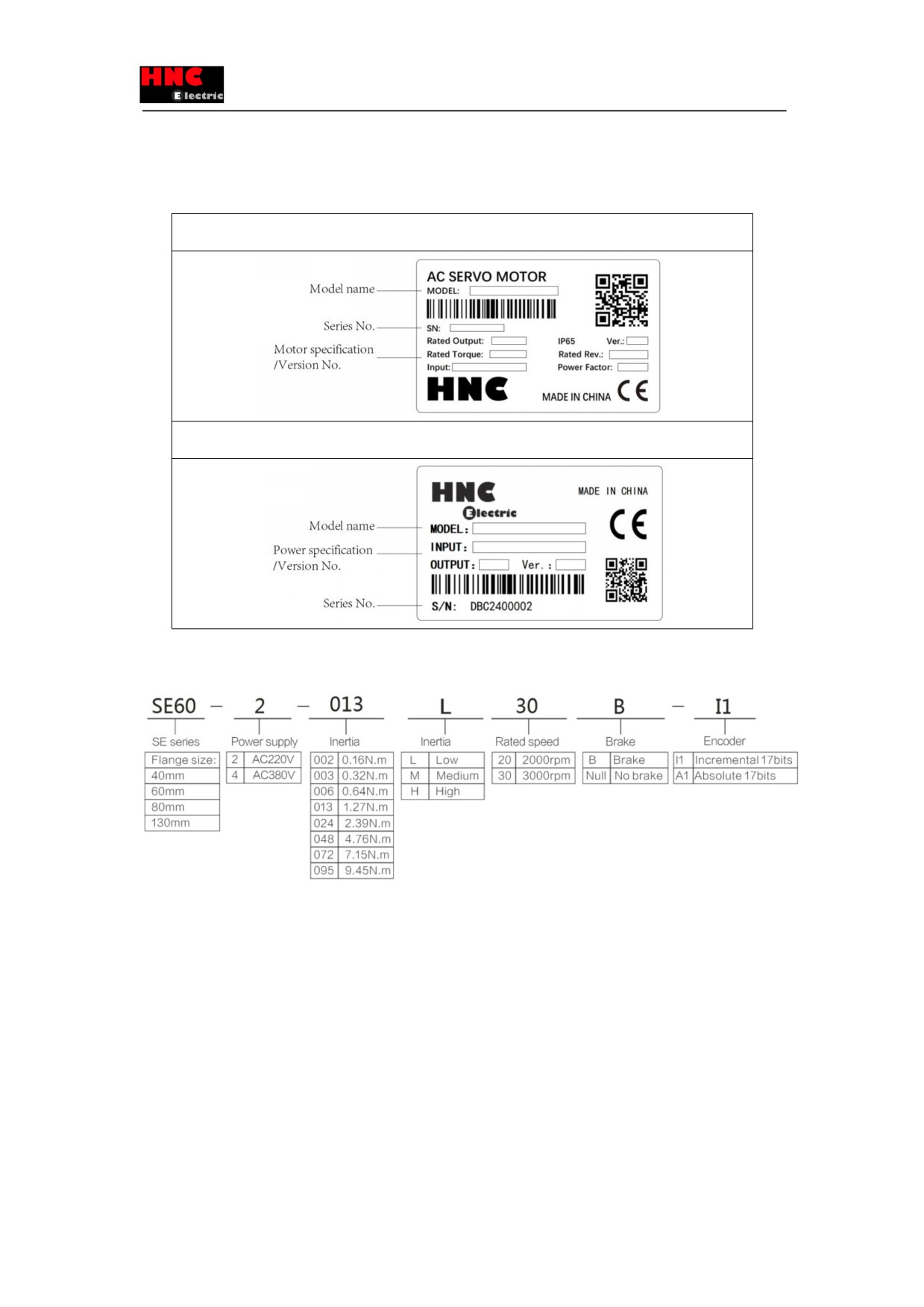
1.1 Introduction of nameplate and model name (For servo motor and drive)
Servo motor nameplate
Servo driver nameplate
Model name
1) Servo motor
Detailed explanation of model naming, take SE60-2-013L30B-I1 as example:
“SE” is motor series,
“60” is motor flange size,
“2”is AC220V,
“013 ” means rated torque is 1.27NM. “M” meas middle inertia,
“30” means rated speed is 3000rpm,
“B” means with brake,
“I1 means” incremental 17bits encoder
7
2) Servo drive
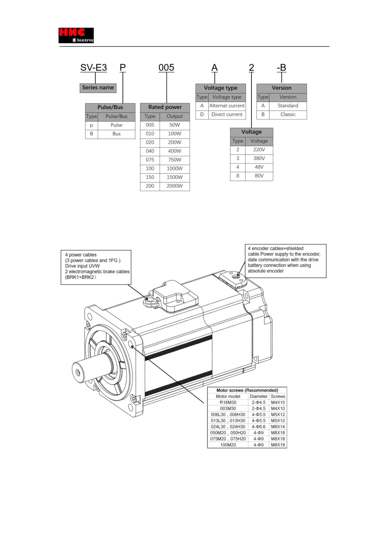
1.2 Parts name of servo motor and drive
Figure 1.1.4 Parts name of servo motor
Figure 1.1.5 Parts name of servo drive
8
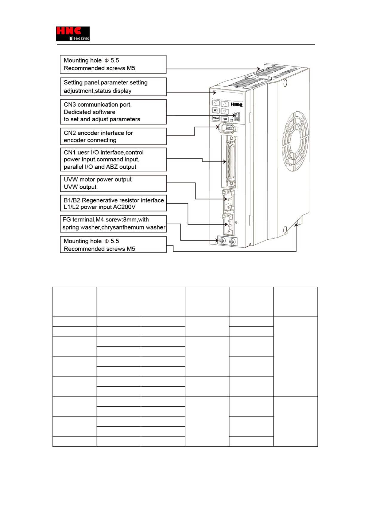
1.3 Model name of servo drive and motor
Capacity
Motor model
Motor size
Drive model
Drive size
SE□□□-2-□□□□□□-A1
(Flange
installation size)
50W
Middle inertia
R16M30
40
SV-E3P005A-A
Frame A
100W
Middle inertia
003M30
SV-E3P010A-A
200W
Low inertia
006L30
60
SV-E3P020A-A
High inertia
006H30
400W
Low inertia
013L30
SV-E3P040A-A
High inertia
013H30
750W
Low inertia
024L30
80
SV-E3P075A-A
High inertia
024H30
1kW
Middle inertia
050M20
130
SV-E3P100A-A
Frame B
High inertia
050H20
1.5kW
Middle inertia
075M20
SV-E3P150A-A
High inertia
075H20
2kW
Middle inertia
100M20
SV-E3P200A-A
9
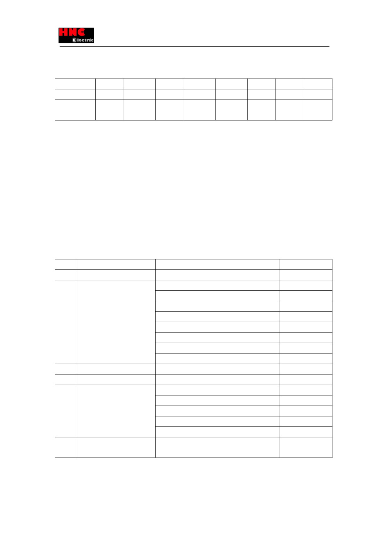
1.4 Model selection of peripheral braking resistor
Rated output
50W
100W
200W
400W
750W
1kW
1.5 kW
2 kW
Resistance
40~50Ω
40~50Ω
40~50Ω
40~50Ω
40~50Ω
30Ω
30Ω
20Ω
Allowable
20W
20W
20W
20W
20W
40W
40W
60W
power
The Status monitoring mode on the setting panel can be used to confirm whether a regenerative resistor is needed. Select
「St_REG」on the setting panel to display 「in00_-」. When the display changes from 「in00_-」 to 「in00_A」, it means the
regenerative resistor is needed. For details, refer to [5.4 Status display mode [Regenerative resistor]].
Starting from low speed operation (20% of the max. speed) to the desired operation and observing if the display value
changes from 「in00_-」 to 「in00_A」 If 「in00_A」displays, a regenerative resistor is needed.
If the regenerative resistor is needed, refer to the installation of regenerative resistor. The use of regenerative resistor cannot
necessarily guarantee the performance. When heating temperature is too high, please increase the resistance, or the
permissible power.
1.5 Selection of cables and connector accessories for HNC ELECTRIC products
● For 750W or less
Items
Usage
Model name
Remark
1
Connector for drive and motor
Power connector (CON-4P-M75A for
750W or less)
2
Power cable
SV-E3-CAB-SE60-PWR-T-R50M
Length: 0.5m
SV-E3-CAB-SE60-PWR-T-1R5M
Length: 1.5m
SV-E3-CAB-SE60-PWR-T-3M
Length: 3m
SV-E3-CAB-SE60-PWR-T-4M
Length: 4m
SV-E3-CAB-SE60-PWR-T-5M
Length:5m
SV-E3-CAB-SE60-PWR-T-6M
Length:6m
SV-E3-CAB-SE60-PWR-T-7M
Length:7m
SV-E3-CAB-SE60-PWR-T-10M
Length: 10m
3
Brake connector
CON-2P-BK (for 750W or less)
4
Encoder cable terminal
SM-6P+172160-1 (for 750W or less)
5
Encoder cable
SV-E3-CAB-SE60-ENC-T-R50M
Length: 0.5m
SV-E3-CAB-SE60-ENC-T-1R5M
Length: 1.5m
SV-E3-CAB-SE60-ENC-T-3M
Length: 3m
SV-E3-CAB-SE60-ENC-T-5M
Length:5m
SV-E3-CAB-SE60-ENC-T-10M
Length: 10m
6
Encoder cable for absolute
SV-E3-CAB-SE60-BOX-T-R30M
Length: 0.3m
(Integrated battery box)
10
● 1KW or more
Items
Usage
Model name
Remark
1
Connector for drive and motor
Power connector (CON-4P-M100A for 1KW or more)
2
Power cable
SV-E3-CAB-SE130-PWR-T-R50M
Length: 0.5m
SV-E3-CAB-SE130-PWR-T-1R5M
Length: 1.5m
SV-E3-CAB-SE130-PWR-T-3M
Length: 3m
SV-E3-CAB-SE130-PWR-T-5M
Length:5m
SV-E3-CAB-SE130-PWR-T-10M
Length: 10m
3
Brake connector
SM10-AP2S-S-C (for 1KW or more)
4
Encoder cable terminal
SM-6P+SM10-SP10S-M-C (for 1KW or more)
5
Encoder cable
SV-E3-CAB-SE130-ENC-T-R50M
Length: 0.5m
SV-E3-CAB-SE130-ENC-T-1R5M
Length: 1.5m
SV-E3-CAB-SE130-ENC-T-3M
Length: 3m
SV-E3-CAB-SE130-ENC-T-5M
Length:5m
SV-E3-CAB-SE130-ENC-T-10M
Length: 10m
6
Encoder cable for absolute
SV-E3-CAB-SE130-BOX-T-R30M
Length: 0.3m
(Integrated battery box)
7
50P pulse connector
Pulse connector CON-50P
2. Product specifications
2.1 Servo drive specifications
2.1.1 Common specifications
Table 2.1.1 Common specifications
Items
Specification
Model Name
005
010
020
040
075
100
150
200
SV-E3P□□□-A
Applicable motor
50W
100W
200W
400W
750W
1kW
1.5kW
2kW
Dimension W(mm)
40
48
61
H(mm)
160
160
160
D(mm)
135
135
175
Weight(Kg)
0.7
0.8
1.5
Input
Main circuit
Single-phase 200~240V
±10%
50/60Hz
Three-phase 200~240V ±10%
power
power
[Note] For the control power, refer to Note 1.
50/60Hz
Control
D3P: DC24V±10% 260mA (Typ.)/Inrush current is excluded.
I/O power supply:24VDC±10%
power
100mA The power is supplied from
internal.
Control type
Three-phase PWM inverters sine-wave driven
Output
Current
0.6
0.9
1.7
2.7
4.3
5.6
9.9
12.2
spec.
(Arms)
11
Frequenc
0 ~ 400
0~333
0~300
0~250
y(Hz)
Encoder feedback
17-bit serial incremental/ absolute encoder
Control
Input
8 points (24VDC, photocoupler insulation) Switched under control mode
signal
Output
8 points (24VDC, photocoupler insulation , open-collector circuit output) Switched under control
mode
Analog
Input
1 point (
±10V) Switched under control mode
signal
Pulse
Input
RS-422 differential, open-collector circuit
signal
Output
A/B/Z-phase RS-422 differential
Open collector output enabled only for Z-phase alone.
Communication
USB: Connection with PC
function
RS-485: remote upper control communication (support multi-station)
Regeneration
External regenerative resistor possible (Note 2)
function
Dynamic brake
None(Note 3)
Control mode
Position control, internal position control, speed control, internal speed control, torque control
Control input
Servo ON, alarm reset, command input prohibition, deviation counter clear,
torque limit selection, CCW/CW drive prohibition
Control output
Alarm state, servo ready, positioning complete, brake release, servo state,
torque limit output
Pulse
Maximum
RS-422 differential:4Mpps
input
command pulse
Open collector: 200kpps
frequency
Input pulse signal
Pulse+ direction, A-/B-phase orthogonal phase difference pulse, CW+CCW
form
pulse(note 4)
Command pulse
A/B A : 1~65535 B : 1~65535 1/1000 < A/B < 1000
multiplication
Smoothing
FIR filter
Pulse
Output pulse signal
Encoder position pulse is output in the following manner:
output
format
A-/B-phase orthogonal phase difference pulse and Z-phase pulse is output
in
RS-422 differential format, Z-phase pulse is output through open collector
Control input
Servo ON, alarm reset, deviation counter clear, CW start, point selection 1, point
selection 2, point selection 3, point selection 4, home position sensor input
Control output
Alarm state, servo ready, brake release, servo state, torque limit output,
operation completion, home position reset completion
Operation mode
Point table, communication operation, manual input pulse
Pulse
Output pulse signal
Encoder position pulse is output in the following manner:
output
format
A-/B-phase orthogonal phase difference pulse and Z-phase pulse is output in
RS-422 differential format, Z-phase pulse is output through open collector
Control input
Servo ON, alarm reset, command inhibited(Zero speed clamp), torque limit
selection 2, CCW/CW rotation prohibition
Control output
Alarm state, servo ready, brake release, servo ON, torque limit output
12
Analog input
Speed
Input voltage -10V to +10V (Maximum speed occurs at ±10V)
command
input
Smoothing
IIR filter, FIR filter
Pulse output
Output pulse
Encoder position pulse is output in the following manner:
signal format
A-/B-phase orthogonal phase difference pulse and Z-phase pulse is output in
EIA-422 differential format, Z-phase pulse is output through open collector
Control input
Servo ON, alarm reset, internal speed command -start 1 &2, internal speed
command 8-phases, torque limit selection 2
Control output
Alarm state, servo ready, brake release, servo ON, torque limit output
Pulse output
Output pulse
Encoder position pulse is output in the following manner:
signal format
A-/B-phase orthogonal phase difference pulse and Z-phase pulse is output in
EIA-422 differential format, Z-phase pulse is output through open collector
Control input
Servo ON, alarm reset, command input prohibition(zero torque command),
torque limit 2, CCW/CW drive prohibition
Control output
Alarm state, servo ready, brake release, servo state, torque limit output
Pulse output
Output pulse
Encoder position pulse is output in the following manner:
signal format
A-/B-phase orthogonal phase difference pulse and Z-phase pulse is output in
EIA-422 differential format, Z-phase pulse is output through open collector
Robust observer
Provided
Vibration control
Provided
Auto-tuning
Provided
Encoder output division and
Provided
multiplication
Tuning/function setting
Adjusted via software
Protective
Hardware
overvoltage, power supply error, overcurrent, overtemperature, overload(refer to
function
alarm
subsection 2,1,1 overload detection description), encoder error
Software
overspeed, too much position deviation, parameter error
alarm
Temperature
Ambient temperature for use
0~55°C(Note 5, Note 6)
Ambient temperature for storage
-20~65°C
Humidity
Ambient humidity for use
20~85%RH or less(Without condensation)
Ambient humidity for storage
20~85%RH or less(Without condensation)
Atmosphere for use& storage
Indoors(Not subject to direct sunlight); free from corrosive
gas, flammable gas, oil mist, or dust
Altitude
1000m or less above sea level
Vibration
5.8m/s2(0.6G) or less, 10~60Hz(No continuous operation
allowed at frequency of resonance)
Dielectric strength
1 minute at 1500 VAC across the primary and FG
Points to note
Grounding is mandatory. ClassⅠrelevant products
”Over voltage categoryⅡ” relevant products
“Pollution degree2” relevant products
Note 1) 24VDC external power supply, as the control power, should meet the following specifications.
13
1. Use SELV power.
※SELV power: Safety Extra Low Voltage
Reinforced insulation is needed for safety extra low voltage, non-dangerous voltage and dangerous voltage
As the overcurrent protection for drive failure, please select the power supply of 100W or less.
Current consumption is the value of I/O signal without the connection of servo ON.
Increase the current consumption for the I/O signal occupied points in the actual usage.
Note 2) The installation of regenerative resistor can be confirmed by the set panel.
1. Select
in the Status Display mode.
2. Show the regenerative state
3. When the device reaches the actual working speed from the low speed (about 20% of the highest speed), confirm the set
panel display is changed to
4. When the panel changes to
, install the regenerative resistor according to [table 1.4.1 Model selection of
peripheral braking resistor].
5. The regenerative resistor value in table 2-2-2 cannot guarantee the performance. If the heating temperature is too high,
please choose the large and high power resistor.
Note 3) The brake is the dynamic brake function controlled by the software.
The brake function becomes invalid when the drive failure occurs or the power supply disconnect.
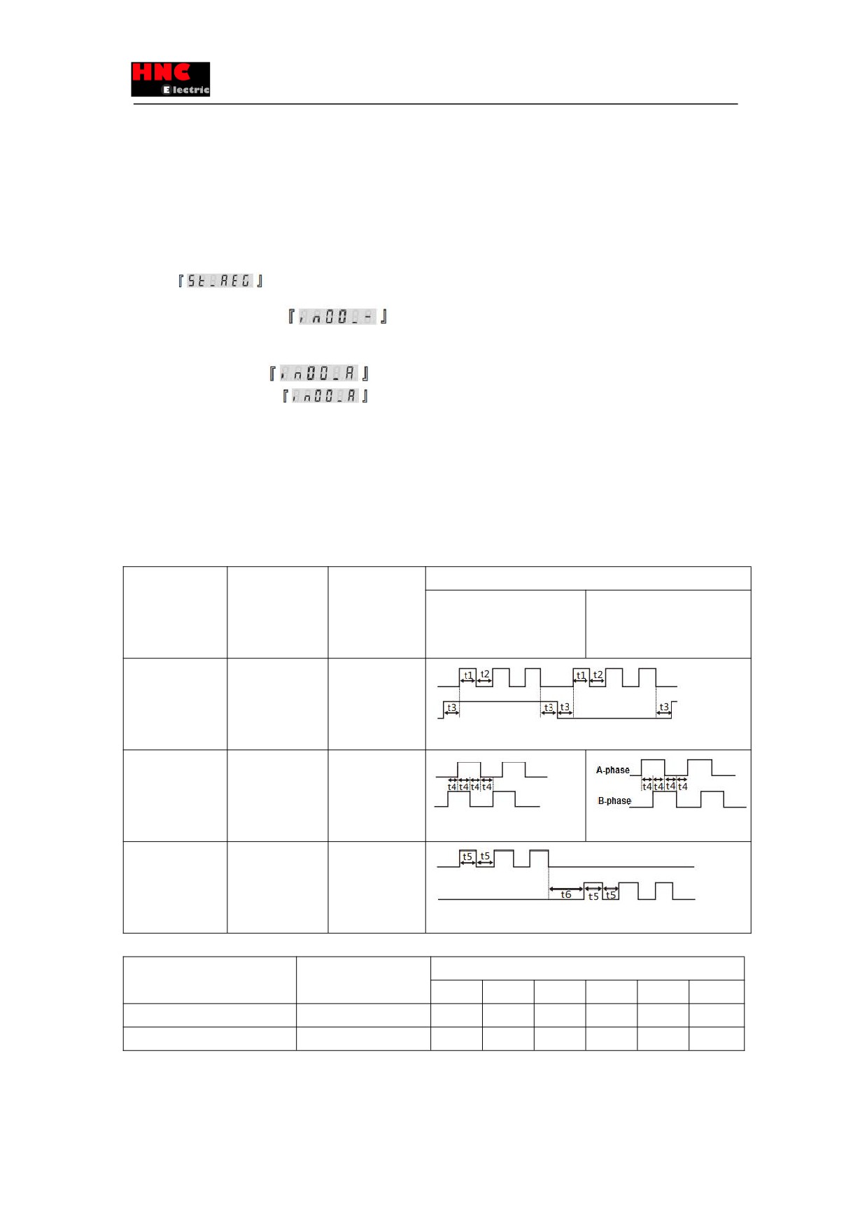
Note 4) Pulse command input is shown below.
Table 2.1.2
Parameter
Input signal
Signal name
The minimum necessary time range (t1, t2, t3, t4, t5, t6)
No.32.0 pulse
Positive direction
Negative direction
command input
mode
0
Pulse · direction
Pulse
(Initial value)
Command pulse
CMD_PLS
Direction
CMD_DIR
1
AB-phase
A-phase
orthogonal phase
CMD_PLS
pulse
B-phase
CMD-DIR
2
Positive direction
CCW CMD-PLS
pulse
CW CMD-DIR
Negative
direction pulse
■Max. pulse frequency and minimum pulse width of command input pulse signal.
Input pulse signal I/F
Max. pulse frequency
The minimum necessary time [μs]
t1
t2
t3
t4
t5
t6
Differential interface
4Mpps
0.125
0.125
2.5
0.25
0.125
0.125
Open collector circuit interface
200kpps
2.5
2.5
2.5
5.0
2.5
2.5
※The rise and fall time of command pulse input signal should be 0.1μs or less.
※The pulse is counted from Low to High.
※Pulse command input filter selection(No.33.0) should be set according to the input frequency.
14
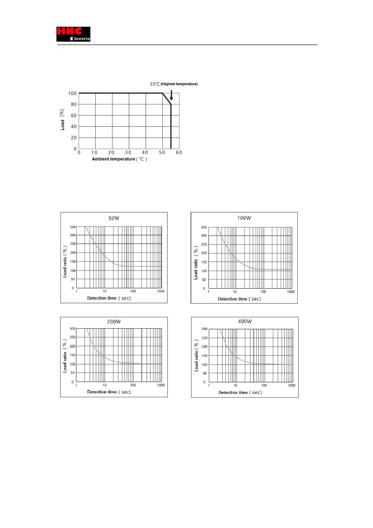
Note 5) Use the screws to fix the drive by the mounting holes according to section 3 [Installation direction and space] to leave
enough space to prevent high temperature.
Note 6) Ambient temperature for 2kW drive(Model name: SV-E3)
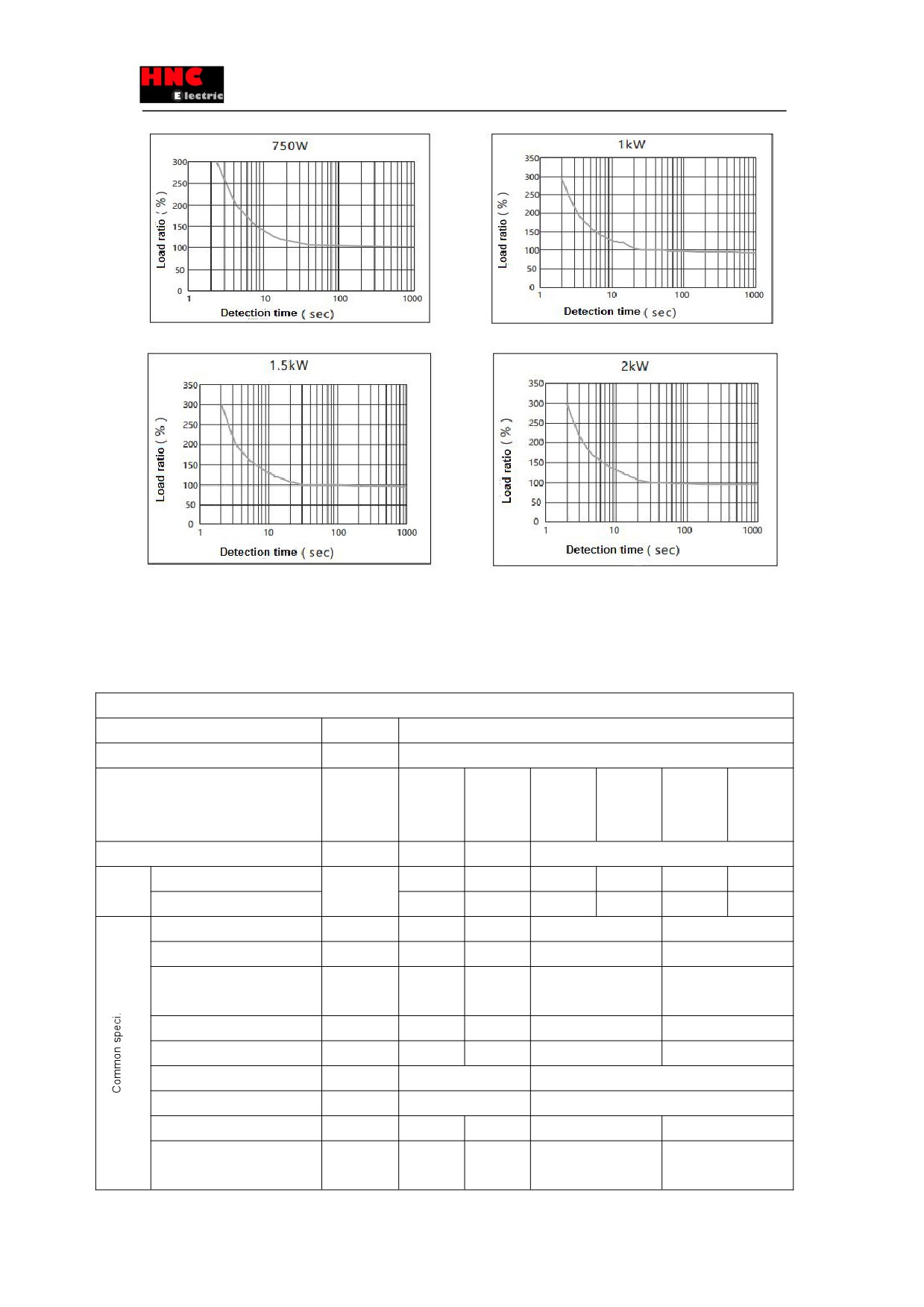
2.1.2 Overload detection characteristics
For SV-E3 series servo drives, when the motor torque exceeds the torque values in the overload detection characteristics,
overload protection will start which outputs overload alarm and the motor stops emergently.
Figure 2.1.1 Overload detection characteristics
15
2.2 Motor specifications
2.2.1 Common specifications
Table 2.2.1 Common specifications
200V~230V AC
Items
Unit
Specifications
Voltage
V
280VDC
Model name
-
002M30
003M30
006L30
006H30
013L30
013H30
(SE□□-2-□□□□□□-□□)
Middle
Middle
Middle
High
Low
High
inertia
inertia
inertia
inertia
inertia
inertia
Flange installation size
mm
□40
□40
□60
Mass
Without brake
kg
0.4
0.5
0.9
1.0
1.3
1.5
With brake
0.6
0.8
1.4
1.5
1.8
2.0
Rated output
W
50
100
200
400
Rated torque
N·m
0.16
0.32
0.64
1.27
Max. instantaneous torque
N·m
0.56
1.12
1.91
3.82
Rated current
Arms
0.6
0.9
1.7
2.7
Max. instantaneous current
Arms
2.1
3.2
5.1
8.1
Rated speed
r/min
3000
3000
Max. speed
r/min
6000
5000
Torque constant
N.m/Arms
0.25
0.36
0.417
0.498
Induced voltage constant of
MV(r/min)
8.8
12.5
14.5
17.4
each phase
16
Rated power
Without
kW/s
5.6
13.6
23.9
9.3
58.7
23.5
change rate
brake
With brake
4.7
12.3
19.5
8.6
51.9
22.4
Mechanical
Without
ms
2.60
1.69
1.12
2.87
2.60
1.66
time constant
brake
With brake
3.06
1.87
1.37
3.12
0.75
1.75
Electrical time constant
ms
0.64
0.76
1.99
2.47
Motor rotor
Without
×10kg·m2
0.045
0.074
0.17
0.43
0.28
0.70
Inertia
brake
With brake
0.053
0.082
0.21
0.47
0.31
0.74
Permissible
Radial load
N
Refer to [2.2.2 Output shaft permissible load]
load
Axial load
N
Encoder
17 bit serial communication (EIA422)
Usage
Holding(Note: not for braking)
Power supply
-
SELV power, reinforced insulation should be performed from the
dangerous voltage.
Rated voltage
V
DC24V±10%
Rated current
A
0.25
0.3
Static friction torque
N·m
0.16 or
0.32 or
1.27 or more
more
more
Absorption time
ms
35 or less
50 or less
Release time
ms
20 or less
15 or less
Release voltage
V
1VDC or more
Rated time
Continuous
Ambient temperature for use
0~40℃(Without condensation)
Ambient humidity for use
20~85%RH(Without condensation)
Ambient temperature for
-20~65℃(Highest temperature guaranteed: 80 degrees, 72hours)
storage
Ambient humidity for storage
20~85%RH (Without condensation)
Atmosphere for use/storage
Indoors(Not subject to rainwater or direct sunlight); free from corrosive gas, flammable
gas, flammables, grinding fluid, oil mist, or dust
Insulation class
Class B
Insulation resistance
1000 VDC megger
5MΩ or more
Dielectric strength
1500 VAC for 1 minute
Altitude
1000m or less above sea level
Vibration class
V 15(JEC2121)
Vibration resistance
49 m/s2
(5G)
Impact resistance
98 m/s2
(10G)
Protective class
IP65
Points to note
Grounding is mandatory. ClassⅠrelevant products
”Over voltage categoryⅡ” relevant products
“Pollution degree2” relevant products
Brake lines have polarity. Red: connected with +24V. Black: connected with GND,
17
200V~230V AC
Items
Unit
Spec.
Voltage
V
280VDC
Model name
-
024L30
024H30
048M20
048H20
072M20
075H20
095M20
(SE□□-2-□□□□□□-□□)
Low
High
Middle
High
Middle
High
Middle
inertia
inertia
inertia
inertia
inertia
inertia
inertia
Flange installation size
mm
□80
□130
Mass
Without
kg
2.5
2.7
5.6
7.6
7.0
9.0
8.4
brake
With
3.3
3.5
7.0
9.0
8.4
10.4
9.8
brake
Rated output
W
750
1000
1500
2000
Rated torque
N·m
2.39
4.77
7.16
9.45
Max. instantaneous
N·m
7.1
14.3
21.5
28.6
torque
Rated current
Arms
4.3
5.6
9.9
12.2
Max. instantaneous
Arms
12.9
16.8
30
36.6
current
Rated speed
r/min
3000
2000
Max. speed
r/min
4500
3000
Torque constant
N.m/Arms
0.61
0.88
0.81
0.85
Induced voltage
MV(r/min)
21.33
30.9
28.4
29.6
constant of each phase
Rated
Without
kW/s
64.1
35.9
50.0
9.2
76.9
13.8
104.9
power
brake
change
With
52.8
32.1
36.5
8.6
61.4
13.3
87.9
rate
brake
Mechanical
Without
ms
0.53
0.94
0.76
4.17
0.60
3.32
0.58
time
brake
constant
With
0.64
1.06
1.05
4.43
0.75
3.46
0.69
brake
Electrical time constant
ms
4.3
10.1
12.2
8.2
Motor rotor
Without
×10kg·m2
0.89
1.62
4.56
24.9
6.67
37.12
8.70
Inertia
brake
With
1.08
1.81
6.24
26.4
8.35
38.65
10.38
brake
Permissible
Radial
N
Refer to [2.2.2 Output shaft permissible load]
load
load
Axial load
N
Encoder
17 bit serial communication (EIA422)
Usage
Holding(Note: not for braking)
18
Power supply
-
SELV power, reinforced insulation should be performed from the dangerous
voltage.
Rated voltage
V
DC24V±10%
Rated current
A
0.4
1.0
Static friction torque
N·m
2.39 or more
9.55 or more
Absorption time
ms
70
120
Release time
ms
20
30
Release voltage
V
1VDC or more
Rated time
Continuous
Ambient temperature for
0~40℃(Without condensation)
use
Ambient humidity for
20~85%RH(Without condensation)
use
Ambient temperature for
-20~65℃(Highest temperature guaranteed: 80 degrees, 72hours)
storage
Ambient humidity for
20~85%RH (Without condensation)
storage
Atmosphere for
Indoors(Not subject to rainwater or direct sunlight); free from corrosive gas, flammable gas,
use/storage
flammables, grinding fluid, oil mist, or dust
Insulation class
Class B
Insulation resistance
1000 VDC megger
5MΩ or more
Dielectric strength
1500 VAC for 1 minute
Altitude
1000m or less above sea level
Vibration class
V 15(JEC2121)
Vibration resistance
49 m/s2
(5G)
Impact resistance
98 m/s2
(10G)
Protective class
IP65
Points to note
Grounding is mandatory. ClassⅠrelevant products
”Over voltage categoryⅡ” relevant products
“Pollution degree2” relevant products
Brake lines have polarity. Red: connected with +24V. Black: connected with GND,
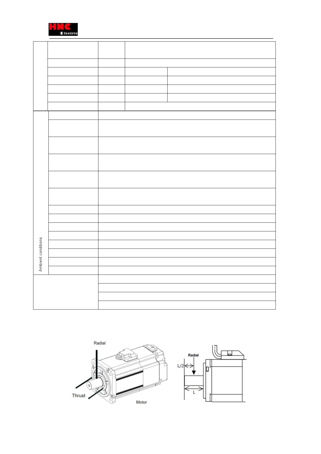
2.2.2 Output shaft permissible load
Figure 2.2.1 Output shaft permissible load
19
//////////////////////