SERVO DRIVE SV-E3 SERIES. INSTRUCTION MANUAL (v1.5) - page 3

SET
Item or value select/confirm
UP
Selected value (flicker) increase
UP (long-press)
Selected value (flicker) increase rapidly
DOWN
Selected value(flicker) decrease
DOWN(long-press)
Selected value(flicker) decrease rapidly
SHIFT
Selected cursor moves left.
SHIFT+DOWN
The screen lock/unlock
SHIFT+UP
Reset the servo drive
SHIFT+S, long press for
The servo drive enabling ON/OFF
2s or more
5.3 Operation mode change
The operation procedures of changing operation mode by set panel are shown below.
Turn on the control power to the drive, the set panel will show
. Press the MODE button once, it will show
Speed feedback(motor speed r/min). Press the MODE button once again, it comes to the Status display mode and shows
「 dP_St 」 . When press the MODE button again, it will come to Alarm display mode, Parameter setting mode, Auto tuning
mode, Parameter saving mode in turn. Press the MODE button again, it returns to the Status display mode. Press the SET
button to come to the selection of operation mode.
40
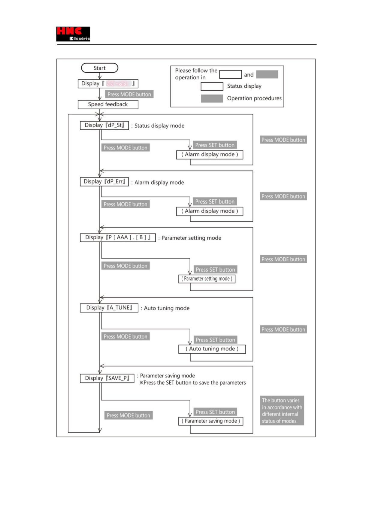
Figure 5.3.1
41
5.4 Status display mode
The operation procedures of Status display mode are shown below.
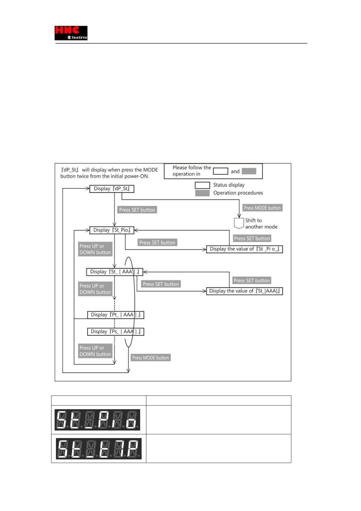
Press the “MODE” button twice from the beginning to get into status display mode and 「dP_St」 displays. Model code and
serial number can be checked in this mode.
Status mark number will be displayed on the right side of「St_」 when press “SET” button. As for the meaning of status mark,
refer to 「Status display list」 or
「Status description」. The status mark number will display alternatively when press “UP”
or “DOWN” button. When status displays, press "SET" button to display its value.
Model code and serial number will be displayed after the status when press “UP” or “DOWN” button. The status mark number
will display alternatively. Model code will be displayed in 「Pt_[AAA]」 and serial number displayed on 「Ps_[AAA]」. In the
display _[AAA], 「Jot」indicates the motor, 「drv」indicates the drive and 「Enc」indicates the encoder.
Figure 5.4.1
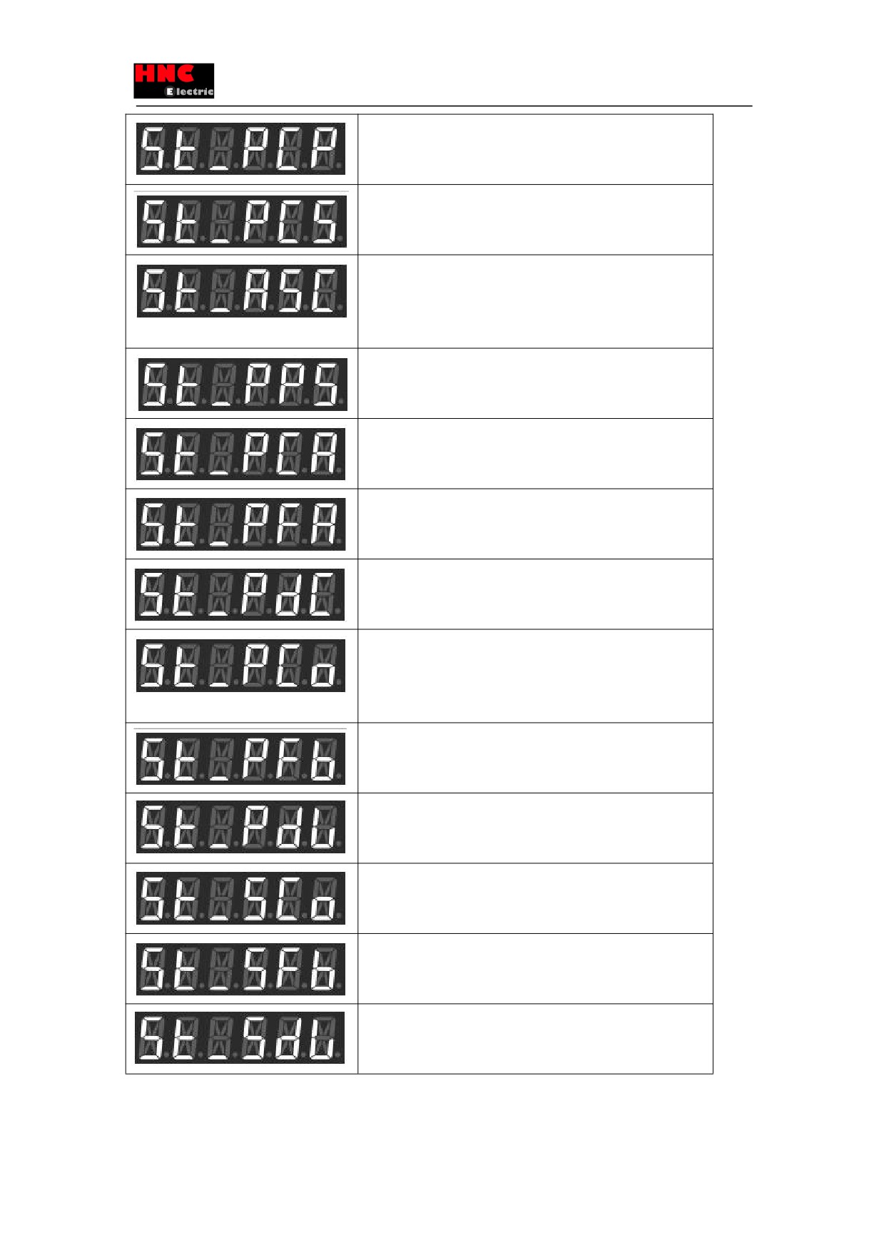
Table 5.4.1 Status display list
Mark number
Status
Parallel I/O status
Display the bit number of assigned parallel IO.
For details, refer to [About parallel I/O status]
Temperature at the control part[℃].
Temperature at the control part of servo drive.
42
Command pulse input (position)[pulse]
To confirm the number of pulse from upper controller.
Command pulse input (speed)
Differential of Command pulse input (position)
Less than 750W: [pulse/160μs], more than 1kW: [pulse/200μs]
Analog command input(command value)[r/min]
By adding input filter and gain, the analog speed command from
upper control device can be regarded as input value of speed
command.
Positioning completion
0: during positioning; 1: positioning completed.
ABS position command [pulse]
Display the position command value according to the command
pulse
ABS position feedback[pulse]
Display the motor position feedback by encoder according to
command pulse
Command position deviation[pulse]
Display the difference value between the position command and
position feedback according to command pulse.
Position command[pulse]
Pulse command input(position). The command value input after
division and multiplication smoothing in internal position command.
Encoder pulse.
Position feedback [pulse]
The actual position values detected by encoder.
Position differential [pulse]
Display the differential between position command value and position
feedback value.
Speed command [r/min]
The value input into the position and speed control of drives.
Speed feedback [r/min]
Motor speed detected by encoder.
Speed deviation[r/min]
Differential between speed command and speed feedback value.
43
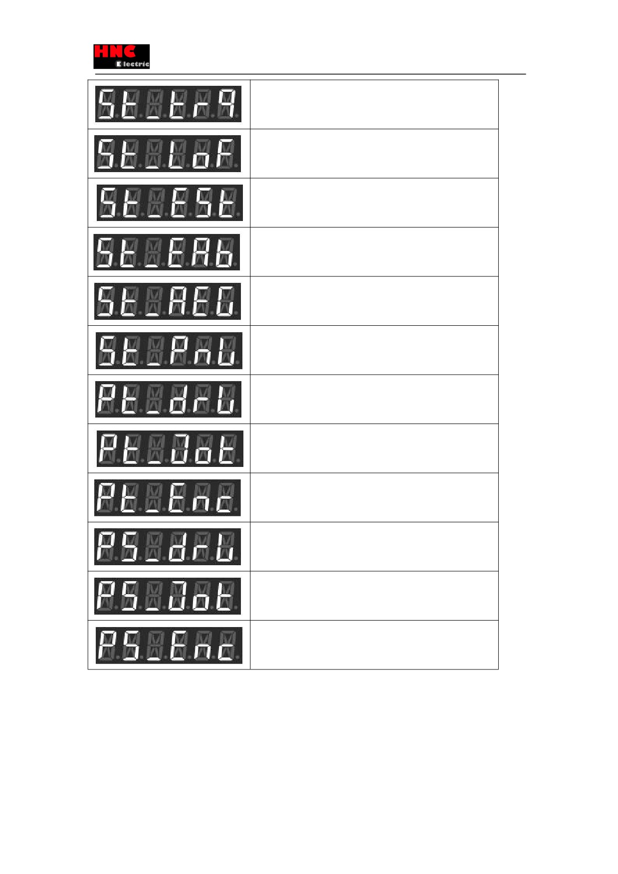
Torque command[0.1%]
The corresponding rated torque of 1000 is 100%, and corresponding
rated torque of 3000 is 300%.
Load ratio[digit]
Permissible value is about 1000(load ratio 100[%]), overload error
occurs when the load continuously exceed 1440s.
Encoder/Rotor mechanical angle (1 rotation) [pulse]
1 rotation absolute angle data of rotor output by the encoder
Encoder/Rotor mechanical angle (integrate) [pulse]
Multi-rotation integrate angle data of rotor output
by
the
encoder
when using absolute encoder.
Regenerative status
Display regeneration status.
For details, refer to [4-4-4 Regenerative status].
Main circuit voltage[0.1V]
Display the main circuit voltage.(reference value)
※Display only in the model「DA2□□2*」
Model code of servo drive.
Display the model code of servo drive.
Model code of servo motor.
Display the model code of servo motor.
Model code of encoder.
Display the model code of encoder.
Serial number of servo drive.
Display the serial number of servo drive.
Serial number of servo motor.
Display the serial number of servo motor.
Serial number of encoder.
Display the serial number of encoder.
Table 5.4.2 Corresponding display for the letters
44
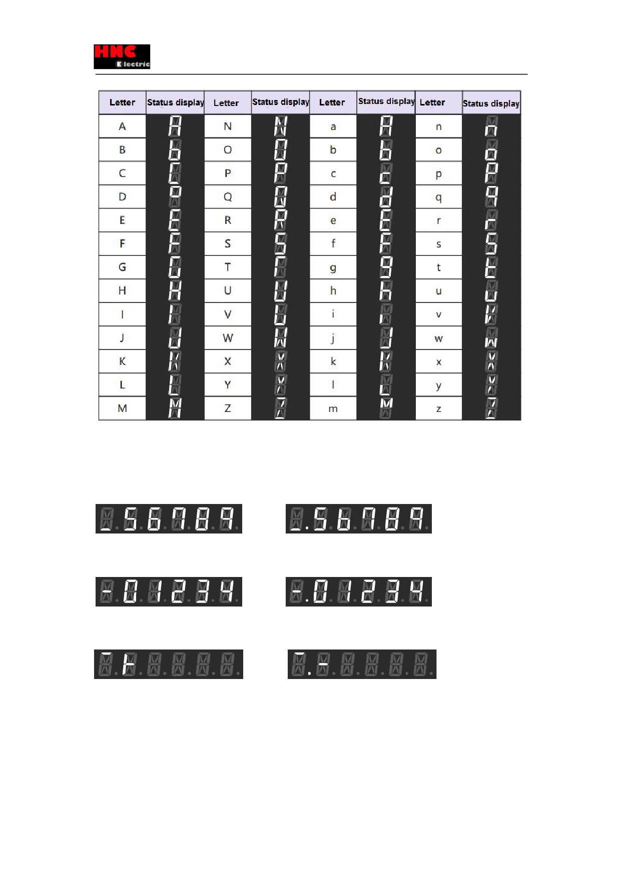
[About LCD display]
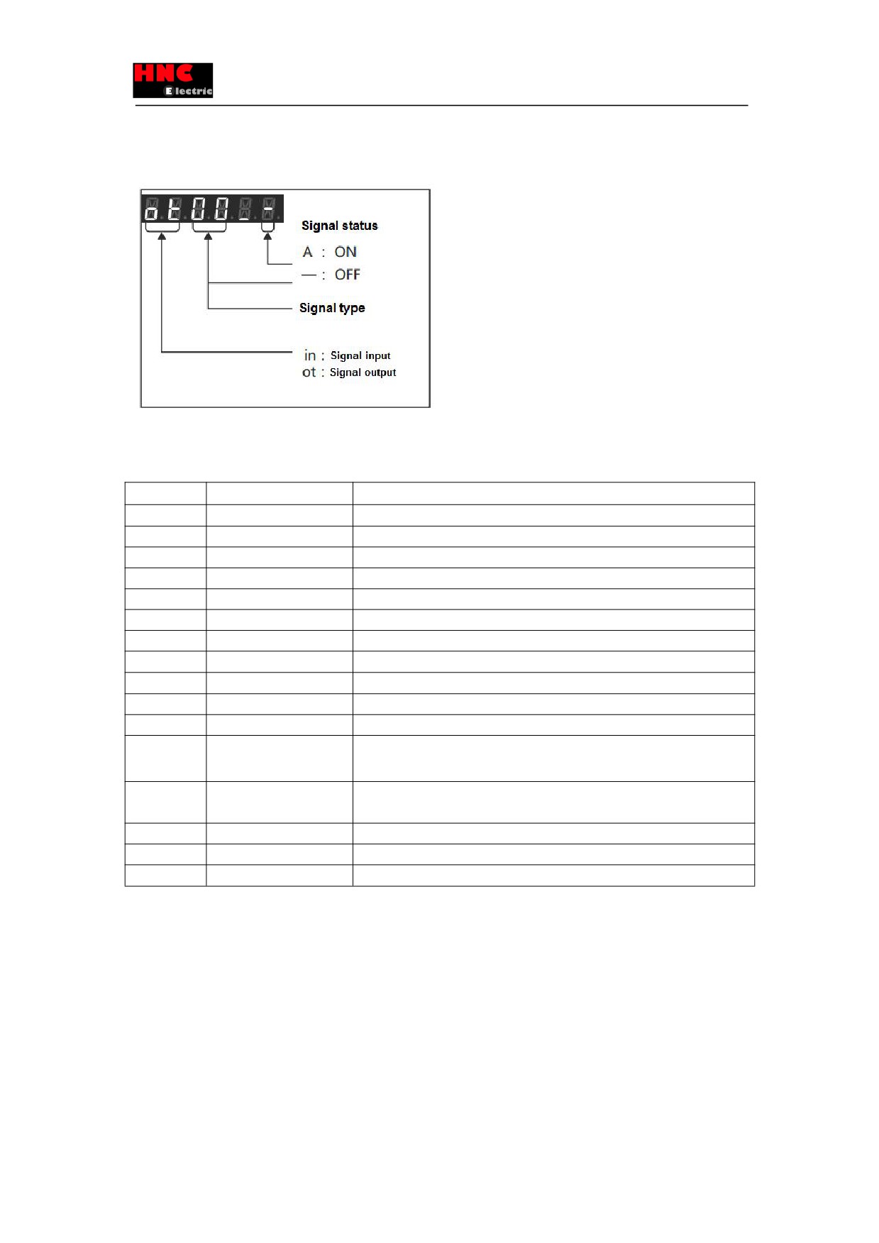
The LCD can display the parameter of more than 6 digits and shows the following screens. Take the positive value
「123456789」and negative value 「-123456789」as example..
1) Screen 1
Display lower 5 digits(lower)
Positive
Negative
2) Screen 2
Display upper 5 digits(middle)
Positive
Negative
3) Screen 3
Symbol display(upper)
Positive(Display「+」)
Negative(Display「-」)
Starting from the right (lower bits) digit, the select cursor moves left when press “SHIFT” button. When the fifth digit
flashes
, press “SHIFT” button and it comes to the next screen. Press “SHIFT” button in Screen 3(Symbol display) and it
comes back to Screen 1(Display for lower 5 digits). That is to say, the screen changes the order of Screen 1(Display for lower
5 digits)→Screen 2(Display for upper 5 digits) →Screen 3(Symbol display) →Screen 1 (Display for lower 5 digits). 「-」on the
left indicates digit position. 「_」indicates the lower digits「―」middle digits; 「 ̄」upper digits. When display negative values,
the left point at the button will always light from lower digit to upper digit. However this left point won’t light When the displayed
45
digital number is less than 6 even if it’s negative.,
[Parallel IO status]
Display the control signal input (8 points) and output (8 points) status of I/O connector (CN1).
The following table lists the signal name of I/O connector (CN1) and parallel IO status display. For the details of user I/O
connector(CN1), refer to 「8.7.1 Signal description」
Table 5.4.3
Display
Signal name
Contents
ot00
O1
(MBRK)
O1 (Brake release output) Output status
ot01
O2
(SERVO)
O2(Servo output)Output status
ot02
O3
(POSIN/-)
O3(Positioning completed /reserved)Output status
ot03
O4
(-)
O4(Reserved)Output status
ot04
O5
(-)
O5(Reserved)Output status
ot05
O6
(OCZ)
O6(Encoder Z phase Open collector output)Output status
ot06
O7
(SRDY)
O7(Servo ready)Output status
ot07
O8
(ALM)
O8(Alarm output) Output status
in00
I1
(SVON)
I1(Servo ON Input) Input status
in01
I2
(RESET)
I2(Alarm reset input) Input status
in02
I3
(HOLD/VCRUN1)
I3(Command input inhibit/Internal speed command-Start 1)Input status
in03
I4
(PCLR/VCRUN2)
I4 ( Deviation counter clearing input /Internal speed command-Start 2 ) Input
status
in04
I5
(-/VCSEL1)
I5(Reserved/ Internal speed command—Speed command selection 1)Input
status
in05
I6
(CCWL/VCSEL2)
I6(CCW drive restriction /Speed command selection 2 Input) Input status
in06
I7
(CWL/VCSEL3)
I7(CW drive restriction / Speed command selection 3 Input) Input status
in07
I8
(TLSEL1)
I8(Torque limit input)Input status
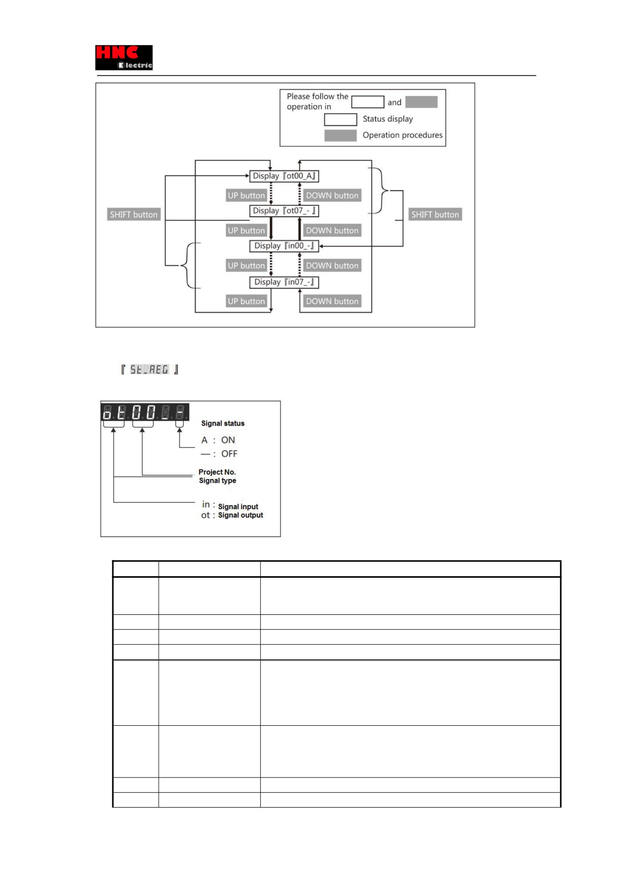
The operation procedures of parallel IO status are shown below.
Press the “UP” or “DOWN” button, the number will be displayed alternatively. When input signal displays, press “SHIFT”
button and it will shift to output signal 「ot00」. When output signal displays, press “SHIFT” button and it will shift to input signal
「in00」.
Figure 5.4.3
46
[Regenerative status]
Display main circuit DC power supply of drive and the working status of regenerative power circuit.
When
displays in the set panel, press SET button to show the following
Figure 5.4.4
Table 5.4.4 Display list of regenerative status
Display
Name
Description
ot00
Regenerative control output
Indicates the drive working status of regenerative power circuit. When the signal is
ON, regenerative power is under the operation by regenerative resistor.
ot01
Reserved
『-』fixed
:
:
:
ot07
Reserved
『-』fixed
in00
When the DC voltage of main circuit reaches the regenerative voltage alarm, the
Regenerative voltage alarm
signal is ON, which indicates the drive regeneration circuit may be on working state. A
regenerative resistor is recommended to be connected.
When voltage is less than regenerative threshold voltage, the signal is ON.
in01
When the DC voltage of main circuit reaches regenerative threshold voltage, the
Regenerative
thresholdsignal is ON, which indicates the drive regeneration circuit is on working state. A
voltage
regenerative resistor must be connected. If not, the power failure may occur.
in02
Reserved
『-』fixed
:
:
:
47
in07
Reserved
『-』fixed
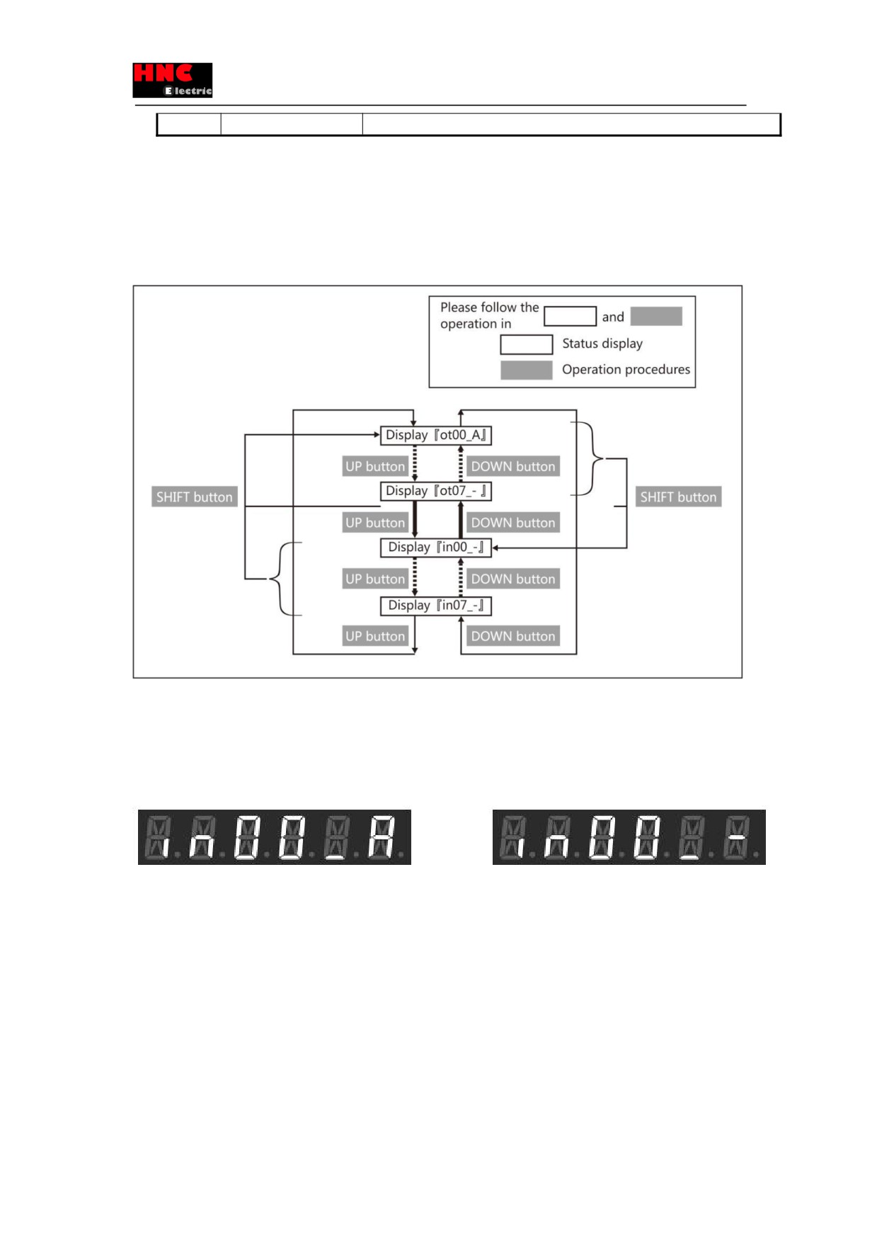
Operating procedures of regenerative status are as follows.
Press the “UP” or “DOWN” button, the number will be displayed alternatively. When input signal displays, press “SHIFT”
button and it will shift to output signal 「ot00」. When output signal displays, press “SHIFT” button and it will shift to input signal
「in00」
Figure 5.4.5
Follow above operating procedures to confirm whether a regenerative resistor is needed or not. When the display changes
from 「in00_-」 to 「in00_A」, the regenerative discharge is opened and the regenerative resistor is needed. For details, refer
to [Regenerative resistor]. Starting from low speed (20% of the highest speed), operating the motor to the expected movement
slowly and observing if the display value changes from「in00_-」to「in00_A」 If 「in00_A」displays, a regenerative resistor
is needed. Operation panel displays as follow:
Need a regenerative resistor
Do not need any regenerative resistor
5.5 Alarm display mode
The following shows the operating procedures of alarm display.
Press the “MODE” button three times from the beginning, 「dP_Err」 indicates the alarm display mode. Press the “SET” button
to display the drive alarm status and 「Err.--」indicates no alarm. If an alarm has occurred, the corresponding alarm number is
output on the right side of 「Err.」. For the details of alarm number, refer to the following [Alarm items]. If several alarms have
occurred, press “UP” or “DOWN” button to display the alarm number.
When an alarm has occurs, 「Err.**」will be displayed on the operation panel except these four modes. (** indicates the alarm
number) ①Parameter setting mode, ②Auto tuning mode , ③In Parameter saving mode, ④Auxiliary functions, when press
48
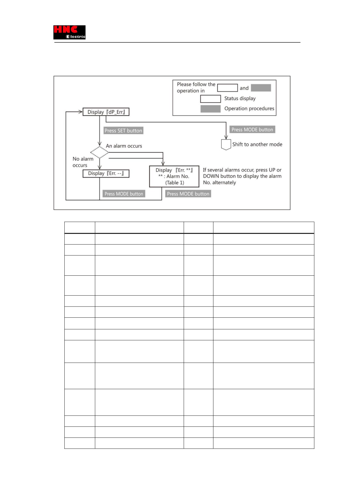
“MODE” button and the display can change from this mode to another, 「Err.**」 will display.
For the remedies and reset method of alarm, refer to [9.2 Alarm disposal and reset].
Figure 5.5.1
Table 5.5.1 Alarm No.
Alarm No.
Alarm description
Alarm No.
Alarm description
00
System error
16
Encoder error (receive data)
01
EEPROM data error
17
Encoder error(no response)
Encoder error (circuit)
02
Model code error
18
04
Overspeed
19
Encoder error (communication)
05
Speed deviation error
20
Encoder error(multi-rotation data)
06
Position deviation error
21
Encoder error(voltage drops)
07
Overload error
22
Power error (control power)
08
Command overspeed error
23
Switch circuit error
09
Encoder pulse output frequency error
24
Overcurrent error
10
Internal position command overflow error/
25
Inverter error 1
Home position return failure
11
Encoder error(multi-rotation counter
26
Inverter error 2
overflow)
12
Overheat
27
Current sensor error
14
Overvoltage
29
Power error (drive internal)
15
Power supply error(main circuit)
49
5.6 Parameter setting mode
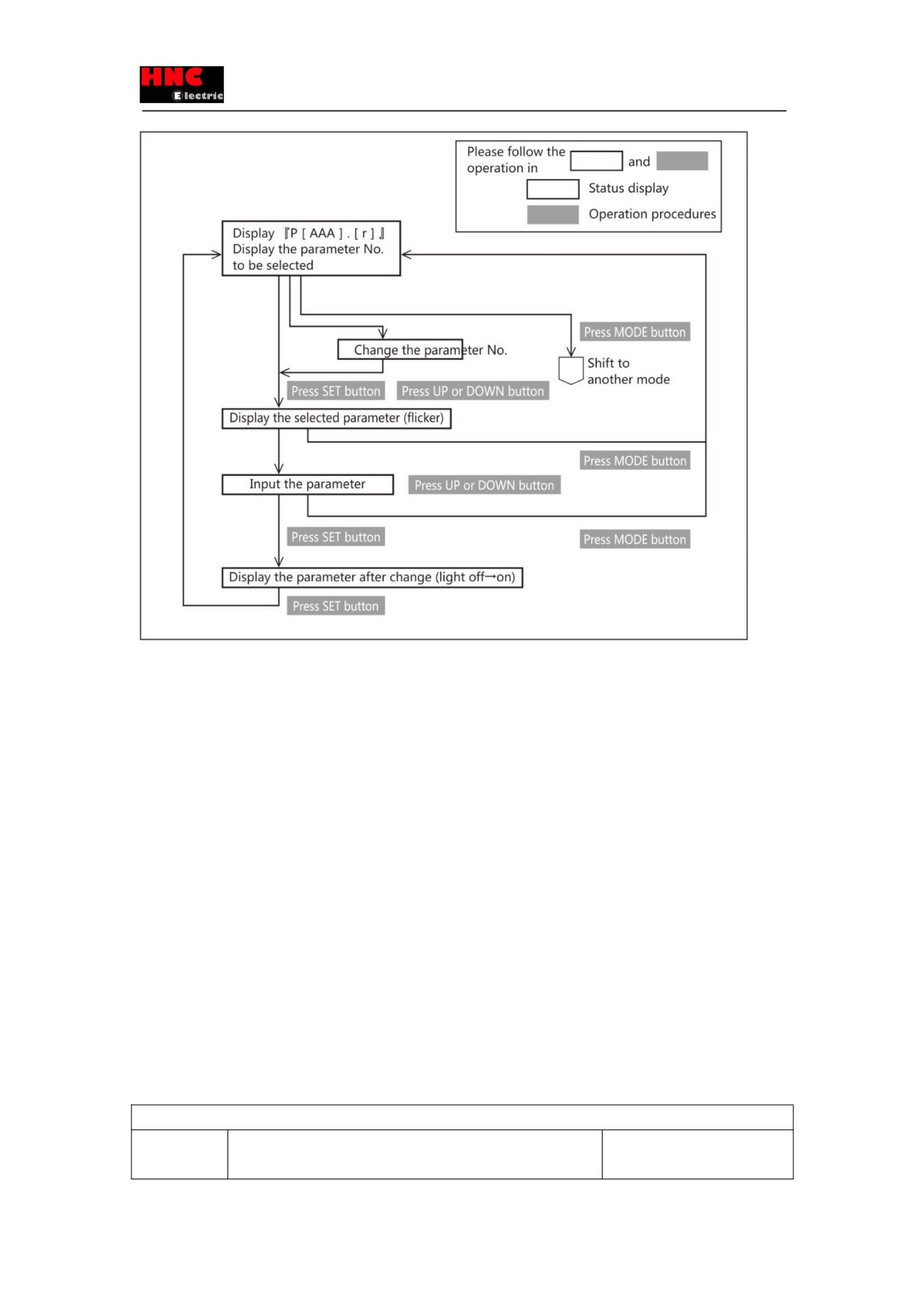
The operating procedures of parameter setting are shown below.
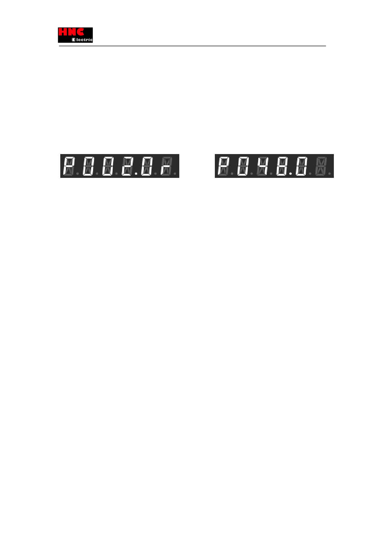
When pressing “MODE” button three times from the initial display, 「P」will be displayed on the leftmost of LCD and it comes
to parameter setting mode. 3 digits, a decimal point, 1 digit and a blank will be displayed in turn on the right side of 「P」. The
combination of 3 digits, a decimal point and1 digit constitute the parameter No. Press UP or DOWN button to the parameter
No. to be set and press SET button to display the parameter value on the servo drive.
For the details of parameter number, refer to [Section 6 Parameter Description]. When「r」is displayed on the rightmost side ,
it means the drive power supply must be restarted after saving the parameter. For the methods of parameter saving, refer to
「Section 5.8 Parameter saving mode」
Restart the power supply to the drive
No need to restart the power supply to the drive
The operating procedures of parameter change are shown below. If parameters displayed, the rightmost LCD will flash and it
comes to the state that parameters can be input.
On the condition that parameter is beyond the range from -99999 to 99999(only for No.087.0 position deviation error
detection value), as said in [Status display mode] and [Signed 6-digit or more parameter on LCD], 5 digits can be displayed
every time. The flashing digit can be changed and press “SHIFT” to select the digit to be changed (flash). Parameter value can
be changed by pressing “UP” or “DOWN” button. Press “SET” button to set the parameter on the drive and the digit will no
longer flicker. If you do not want to change the parameter value and just confirm it, press “MODE” button to return. If the drive
is powered off, the parameter value will return to the state before change.
In order to save the parameter after change in the EEPROM of drive, refer to [Section 5.8 Parameter saving mode] for details.
Figure 5.6.1
50
5.7 Auto tuning mode
Auto tuning mode includes 「Simple adjustment」 and 「Fine adjustment」.
「Simple adjustment」
Select gain level among 5, 10, 15, 20, 30 and then start auto tuning and setting automatically the expected inertia ratio to
achieve the desired operation. Meanwhile, the inertia ratio can be set manually. The most suitable gain can be set
corresponding to inertia ratio.
「Fine adjustment」
To achieve the optimum operation effect after Simple adjustment, some gain parameters need to be set. It’s generally
optimized in accordance with the order of gain level
→ Inertia ratio → FF1 gain. It can also be optimized more easily in
accordance with the order of integral gain→FF2 gain→damping ratio.
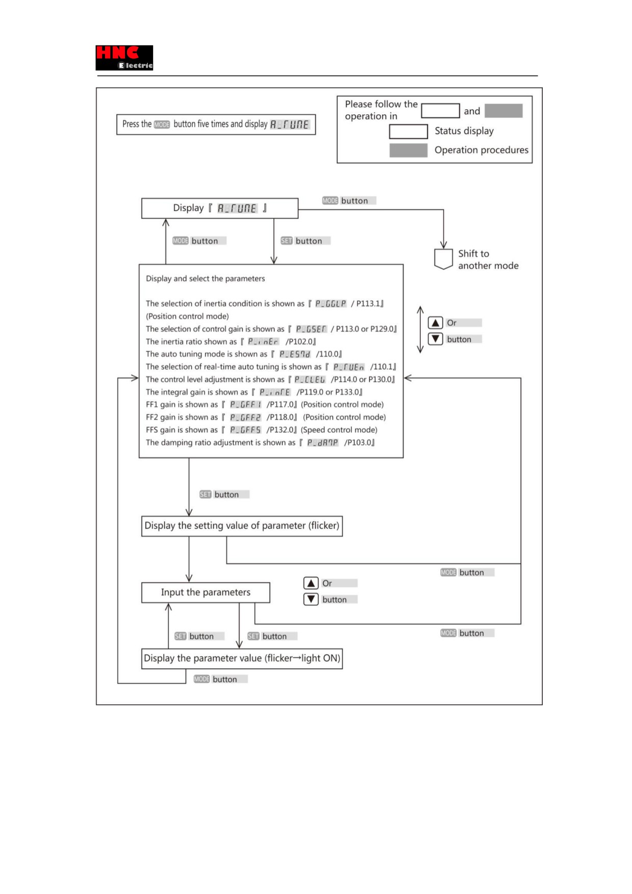
「A_TunE」(Auto tuning mode) will be displayed after press “MODE” button five times from the initial display status.
In auto tuning mode, parameters which are set in Parameter setting mode can be displayed after the 「Simple adjustment」
and 「Fine adjustment」.Please follow the procedures below to operate. This mode will show under position control or speed
control mode.
The parameter group that can be set in position control or speed control mode is as follows. If pressing “SHIFT” button in auto
tuning mode, [Parameter name] on the operation panel will shift to [Parameter number]
Table 5.7.1
Position control
Display order
Name
Parameter
name/
number
displayed on panel
51
1
Inertia condition
P_GGLP / 113.1
2
Control gain setting
P_GSET / 113.0
3
Inertia
ratio
P_inEr /102.0
4
conversion ratio of Inertia ratio
P_inTr /104.0
5
Selection of real-time auto tuning
P_TUEn /110.1
6
Control level
P_CLEv /114.0
7
Integral gain
P_inTE /119.0
8
First gain FF compensation
P_GFF1/117.0
9
Second gain FF compensation
P_GFF2/118.0
10
Damping ratio
P_dAmP/103.0
Table 5.7.2
Speed control
Display order
Name
Parameter
name/
number
displayed on operation panel
1
Control gain level
P_GSET /129.0
2
Inertia ratio
P_inEr /102.0
3
Setting of auto tuning
P_ES7d /110.0
4
Selection of real-time auto tuning
P_TUEn /110.1
5
Control level
P_CLEv /130.0
6
Integral gain
P_inTE /133.0
7
First gain FF compensation
P_GFFS /132.0
8
Damping ratio
P_dAmP/103.0
Figure 5.7.1
52
5.8 Parameter saving mode
「SAVE_P」(Parameter saving mode) will be displayed on the panel if pressing ‘MODE” button six times from the beginning.
The new parameters, set in Parameter setting and auto tuning mode, can be written to EEPROM in the parameter saving
53
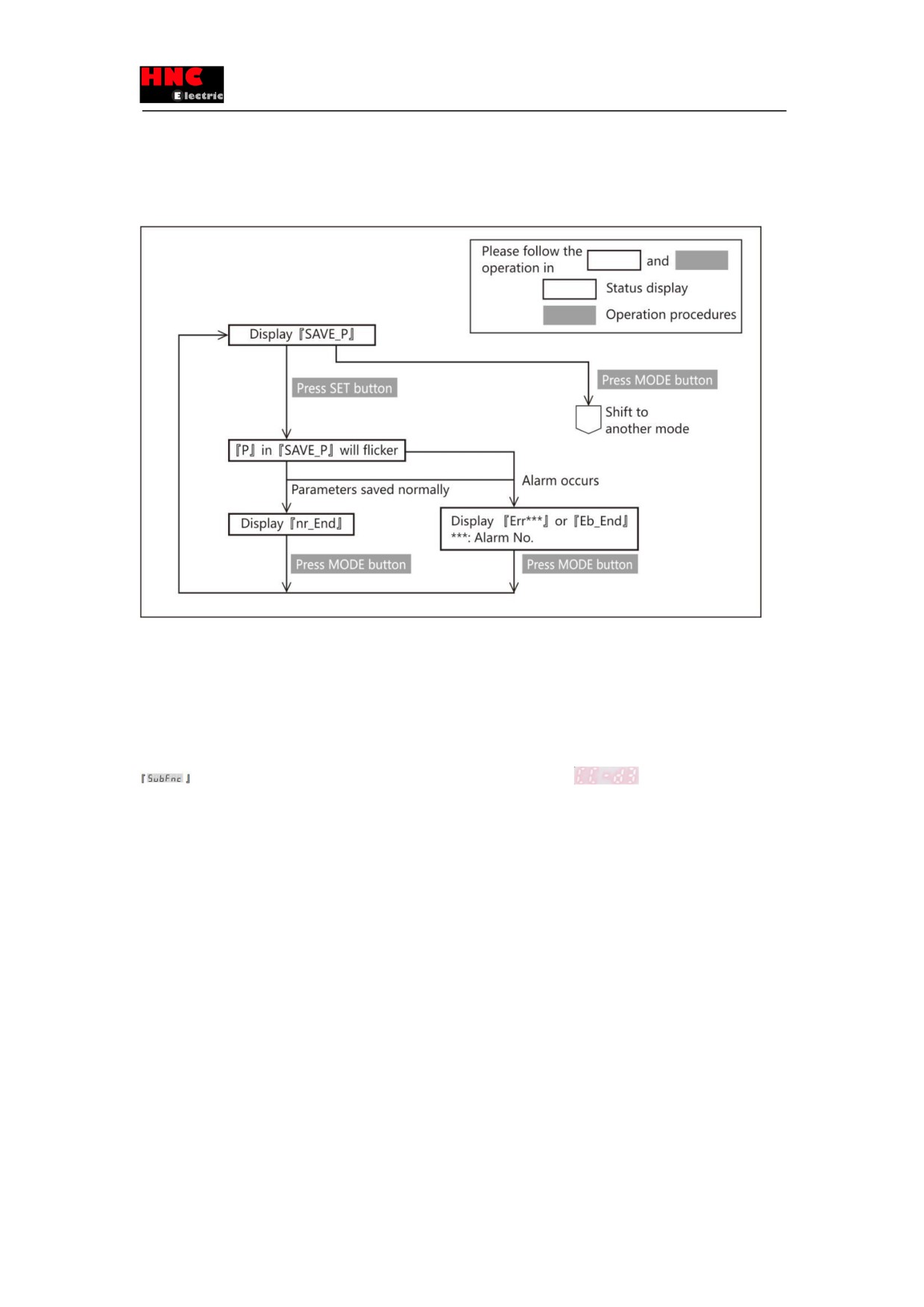
mode. Please note that the newly-set parameters, which have been set in Parameter setting and auto tuning mode but not
saved to EEPROM, will disappear and return to the value before after power-off.
The operating procedures of saving parameters are shown below.
Figure 5.8.1 Parameter saving mode
In parameter setting mode when change the parameters that need restarting 24VDC control power supply, please restart the
control power supply after the above procedures done. The changed parameters become effective after restart control power
supply.(For the models of 1kW or more, power off the main circuit power supply and restart it after the screen display is off)
5.9 Auxiliary function
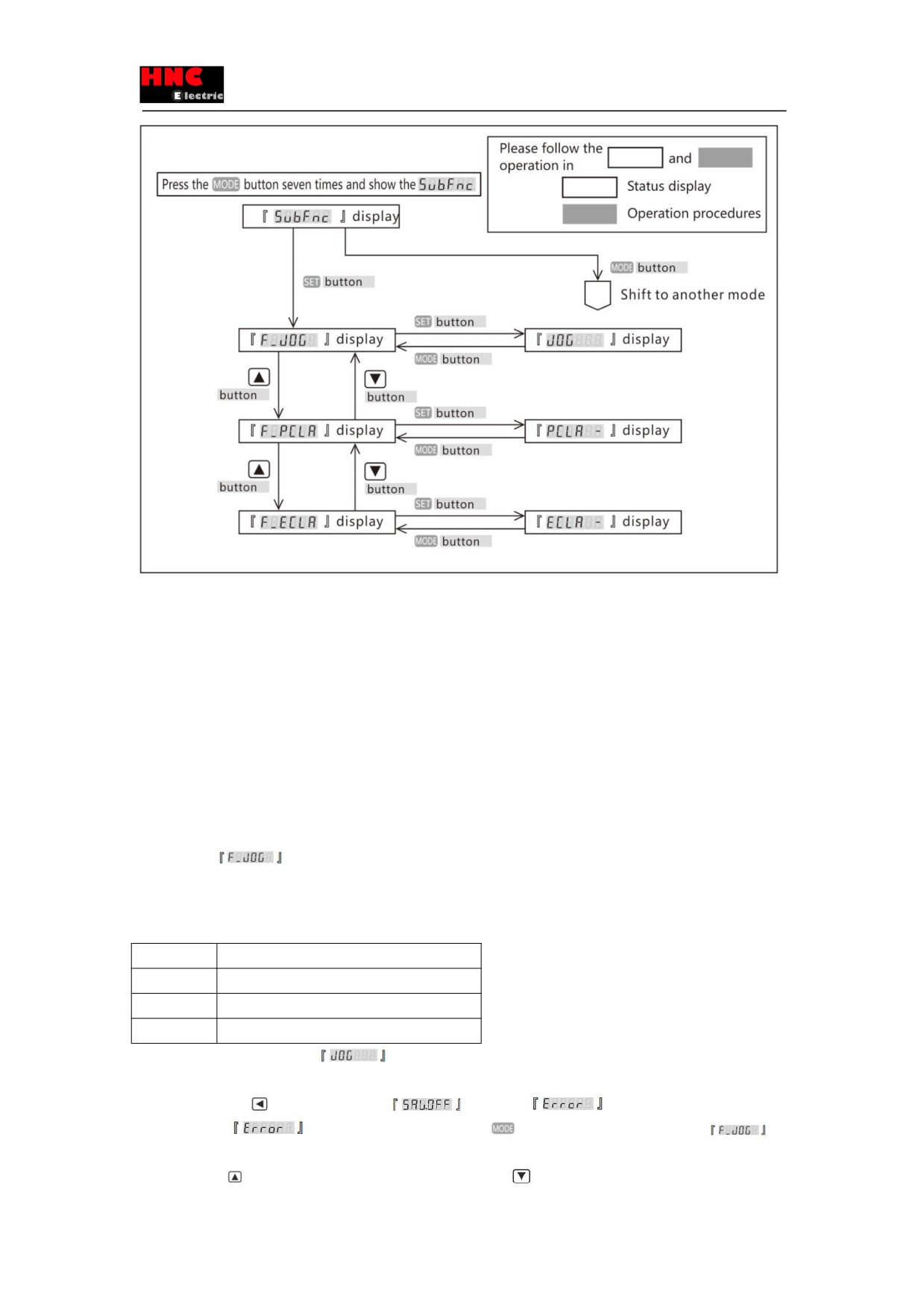
will display after press the MODE button seven times from the initial status
Please operate as the procedures shown in Figure 5.9.1.
Figure 5.9.1 Auxiliary function
54
5.9.1 Drive connector terminal description
JOG function is function for test run without the commands output by the upper controller. Please use the test run function for
the purpose of adjustment. For details.
Working conditions for JOG function
・ The JOG function is available in the pulse command modes of position control and speed control mode. Control the
machines according to the corresponding gain of control modes. Do not use the JOG function in the internal position
command mode (point table, test run) and torque control mode of position control.
・ When using JOG function in speed control mode/ internal speed command mode, the VCRUN1, VCRUN2, VCSEL1,
VCSEL2 and VCSEL3 of parallel I/O input become invalid.
・ Input the 24VDC control power and servo ON signal from I/O connector.
Operating procedures
1. Display the
according to the operating procedures as shown in Figure 5.9.1 Auxiliary function.
2. Set the following three parameters by the set panel .
For the details of parameters, please refer to [Chapter 6 Parameter Description].
Table 5.9.1 Relevant parameter of JOG function
No.
Parameters
385.0
JOG operation: Acceleration time
386.0
JOG operation: Deceleration time(※Note 1)
387.0
JOG operation: Target speed
3.Press SET button and show the
4. Make the servo OFF by I/O
5. Long-press LEFT(
) button and show the
. The alarm
will occur if operating at the servo
ON. If the alarm
occurs at this time, press MODE
button and the display returns to
and
reoperate from procedures 3.
6. Press the UP
button, the motor rotate in CCW direction; if Down
button, in CW direction.
55
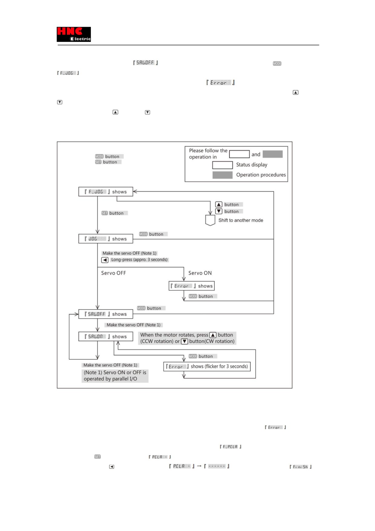
The motor rotates when pressing the button, and stops as releasing the button.
7. Make the servo OFF by I/O and
shows to end the JOG operation. Then press MODE
button and show
, which means the operation status changes from JOG to the general. If the servo is ON, the operation cannot
change from JOG operation to general operation status and the alarm
will occur.
Note 1) Please note that if the JOG operation deceleration time is set longer, the time from pressing the UP
or Down
button to stopping the motor will become longer correspondingly.
Note 2) If press the UP
or Down
button simultaneously, the motor will stop. If the unexpected operating status
happens, switch off the main circuit power or make the servo OFF to stop the operation.
Figure 5.9.2
5.9.2 Parameter clearing function
This function is to return the parameters to the factory settings. After clearing the parameters, restart the power supply and the
parameters will change to the factory settings.
The parameter clearing should be operated at the servo OFF. If the servo is ON, an alarm will occur
Operation procedures
1. Operate as the procedures in section 4.9 Auxiliary function and display the
2.Press the SET
button and show the
3. Long-press the LEFT
button, then display the
and flicker, then change to
4. Restart the power supply and the parameter clearing is done.
56
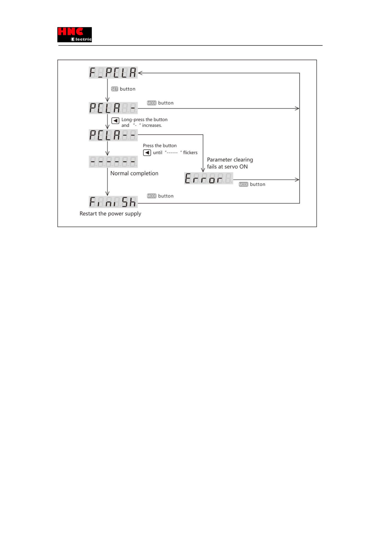
Figure 5.9.3
5.9.3 Encoder clearing function
For details, please refer to [Reference SV-E3 series absolute system].
6. Parameter Description
6.1 Parameter list
This section gives a detailed description of the displayed parameters on the panel.
The column of 「No.」is the parameter number. Two numbers separated by “/” are the numerator and denominator number of
parameters. Take 034.0/036.0 as the example, 034.0 is the numerator number and 036.0 is the denominator number. [Basic
setting] in Parameter list are the initial setting values determined by the device. [Adjustment] indicates gain and other
parameters that need to be adjusted to get the expected operation. [Special setting] indicates the parameters set according to
the actual needs. The parameters with 「r」displayed on the right side of parameter number, are the ones that need to restart
the drive control power supply after saving. 「Yes」will be displayed in the parameters of 「Whether to restart 24VDC power
supply」. After saving the parameters in 「Parameter saving mode」, 「Whether to restart 24VDC power supply」will be
displayed for the parameters which are valid after restarting 24VDC power supply. For the models of 750W or less, the control
power is supplied from external 24VDC. For the models of 1kW or more, the control power is supplied from internal power and
please cut off 220V power of main circuit if restart needed.
<Notice>
Each parameter has its setting range, but it also depends on the setting value of other parameter. There are some parameters
unable to set, even though they are in the setting range. The following is the interdependent parameter number.
No.102.0
Inertia ratio
No.103.0
Damping ratio
No.104.0
Conversion ratio of inertia ratio
No.115.0
Control gain 1 (Position control mode)
57
No.116.0
Control gain 2 (Position control mode)
No.117.0
Gain FF compensation 1(Position control mode)
No.118.0
Gain FF compensation 2(Position control mode)
No.119.0
Integral gain(Position control mode)
No.131.0
Control gain 1(Speed control mode)
No.132.0
Gain FF compensation 1(Speed control mode)
No.133.0
Integral gain(Speed control mode)
6.1.1 Parameters
Table 6.1.1 Parameters
Types
Names
No.
Common
Control mode
2.0
parameters
Command mode
3.0
Operation mode
9.0
Torque command range
Switch
144.0
Value 1
147.0
Value 2
148.0
Torque limit output
144.1
Delay time for Servo off
237.0
Delay time for mechanical brake release
238.0
Selection of an encoder system
257.0
Encoder pulse output
Rotation direction
272. 1
Division and
Numerator
276. 0
multiplication
Denominator
278. 0
RS-485
Switch
8.0
communication
Address
4.0
Communication speed
6.0
Stop bit
6.1
Parity
6.2
Minimum response time
11.0
Error detection
Position error
Switch
65.0
Value
87.0
Delay time
89.0
Speed error
Switch
65.1
Value
90.0
Delay time
91.0
Encoder pulse output
Upper limit for frequency
285.0
Delay time
286.0
Instantaneous voltage
Delay time
305.0
drop
Drive restriction
Settings
67.0
options
Deceleration method
67.1
Stop status
67.2
58
Keep position deviation counting
67.3
Deceleration stop
Method
224.0
Release condition
224.1
Operation time
226.0
Cancel deceleration stop
227.0
Power supply error
Switch
224.2
Operation time
228.0
Torque command range
151.0
Adjustment
Inertia ratio
102.0
Damping ratio
103.0
Auto tuning
Mode switch
110.0
Project
110.1
Position control mode
Control gain set
113.0
Inertia condition
113.1
Control level
114.0
Control gain 1
115.0
Control gain 2
116.0
Gain FF compensation
1
117.0
Gain FF compensation
2
118.0
Integral gain
119.0
Speed control mode
Control gain set
129.0
Control level
130.0
Control gain 1
131.0
Gain FF compensation
1
132.0
Integral gain
133.0
Current control gain
193.0
Position
Filter 1
Selection(*1)
66. 0
command filter
Smoothing filter 1
average moving times
80. 0
Notch frequency
74. 0
Notch width
75. 0
High frequency gain
76. 0
Notch depth
79. 0
Filter 2
Selection
82. 0
Notch frequency
83. 0
Notch width
84. 0
High frequency gain
85. 0
Notch depth
86. 0
Filter 3
Selection
82. 1
Notch frequency
357. 0
Notch width
358. 0
High frequency gain
359. 0
Notch depth
360. 0
Filter 4
Selection(*2)
66.1
59