SERVO DRIVE SV-E3 SERIES. INSTRUCTION MANUAL (v1.5) - page 7

②Orthogonal phase
②Input B phase of AB phase orthogonal phase difference pulse signal from host control
difference B phase
device(differential input)
③CCW+CW pulse CW
③Input CCW+CW of CW pulse from host control device (differential input)
[5V open collector circuit]
[5V open collector circuit] Max. command pulse frequency 200kpps
④5V power supply input of
④5V power supply input terminal of /CMD_DIR.
/CMD_DIR
/CMD_
31
[Differential input]
【Differential input】Max. command pulse frequency
4Mpps
DIR
①Pulse + direction /direction
①Input pulse + direction /direction from host control device(differential input)
②Orthogonal phase
②Input /B phase of AB phase orthogonal phase difference pulse signal from host control
difference /B phase
device(differential input)
③CCW+CW pulse /CW
③Input CCW+CW pulse /CW from host control device (differential input)
[5V/24V open collector
[5V/24V open collector circuit] Max. command pulse frequency 200kpps
circuit]
④Input pulse+ direction of direction from host control device
④Pulse + direction
⑤Input B phase of AB phase orthogonal difference pulse signal from host control device
direction
⑥Input CCW+CW of CW pulse from host control device
⑤Orthogonal phase
difference B phase
⑥CCW+CW pulse CW
A_SPE
32
Analog speed command
●Input speed or torque command in the voltage from -10V to 10V.
ED/
input/ Analog torque
A_TR
command input+
Q
A_GN
33
Signal ground
●Connect the signal ground of analog speed input or analog torque input in the servo drive.
D
Analog speed command
input - /
Signal ground
Analog torque command
input - /
SG
42
Signal ground
●Signal ground of ABZ phase output of position feedback
485
43
485 of RS-485
●485 data (+) signal of RS-485 communication with host control device
communication
/485
44
/485 of RS-485
●/485 data (+) signal of RS-485 communication with host control device
communication
SG
45
Signal ground
●Signal ground of RS-485 communication with host control device
CC-P(
49
[5V open collector input]
[5V open collector input] Max. pulse frequency 200kpps
5V)
①5V for /CMD_PLS
①5V power input terminal of /CMD_PLS
Built-in current limiting
resistor
120
CC-D(
50
[5V open collector input]
[5V open collector input] Max. pulse frequency 200kpps
5V)
①5V for /CMD_DIR
①5V power input terminal of /CMD_DIR
Built-in current limiting
resistor
Table 8.7.2 I/O input signal
Signal
Contents
Function
Control mode
name
P
S
T
○
○
○
SVON
Servo ON
●Servo is ON when connecting COM-.
RESET
○
○
○
Alarm reset
●Reset alarms when connecting to COM-.
●But if alarm occurs in encoder, model No. and system, this signal cannot be used to reset, and
drive control power supply must be restarted(OFF→ON).
HOLD
△
△
○
Command
●When COM- connected, command input is restricted.
input
●If not connected, command input are permitted.
restriction
●Even if pulse is input, the motor cannot operate until the host control device allows command
input.
●When 「Command input prohibited」, whether to clear pulse counter can be set by parameter
No.67.3(the selection of position deviation counter in drive input)
●When the speed command value is 0 in speed control mode, the motor will not operate.
PCLR
△
-
-
Deviation
●When COM- connected, position deviation counter will be cleared.
counter clear
CCWL
△
△
○
CCW drive
●If COM- disconnected, CCW direction drive is prohibited.
restriction
●If the value is beyond the CCW direction movement range, please make the wiring which can
be disconnected with COM-.
●It is effective when 「2: Enable CCW-drive restriction」or「3: Enable CW/CCW-drive restriction
」is selected in parameter No.67.0「Selection of Drive restriction options」. Initial value:
「0:
Disable」
●The deceleration can be selected in parameter No.67.1 「Deceleration method selection when
Drive restriction is enabled 」. Initial value:
「1: Short brake」.
●After-stop state can be selected in parameter No.67.2 「Selection for Stop condition when
Drive restriction is enabled」. Initial value: 「0: Free-run」
●Parameter No.67.3 「Selection for Location deviation counter option when Drive restriction is
enabled」can be set to hold the position deviation counter. Initial value: 「0: Keep」
CWL
△
△
○
CW drive
●If COM- disconnected, CW direction drive is prohibited.
restriction
●If the value is beyond the CW direction movement range, please make the wiring which can be
disconnected with COM-.
●It is effective when 「2: Enable CW-drive restriction」or「3: Enable CW/CCW-drive restriction
」is selected in parameter No.67.0「Selection of Drive restriction options」. Initial value:
「0:
Disable」
●The deceleration can be selected in parameter No.67.1 「Deceleration method selection when
121
Drive restriction is enabled 」. Initial value:
「1: Short brake」.
●After-stop state can be selected in parameter No.67.2 「Selection for Stop condition when
Drive restriction is enabled」. Initial value: 「0: Free-run」
●Parameter No.67.3 「Selection for Location deviation counter option when Drive restriction is
enabled」can be set to hold the position deviation counter. Initial value: 「0: Keep」
TLSEL1
Torque limit
△
○
○
●Torque limit switch.
●It is effective when 「1: Enable」 is selected in parameter No.144.0「Enable/Disable Torque
command limit Override」
●At open circuit, the parameter No.147.0「Torque command limit Override 1」is preferred. At
power On, the parameter No.148.0「Torque command limit Override 2」is preferred.
PCSTAR
CW start
△
-
-
●It is effective when the parameter No.642.0 「Internal speed command - Operation mode」 is
T1
set to “0=Point table”.
●When PCSEL1 to 4 is specified to point No. and connected to COM-, point table No. and home
position reset can execute.
PCSEL1
Selection 1 of
△
-
-
●Specify the point No. and home position reset to be executed.
point No.
●According to the setting of parameter No.646.3 「Point No.0 function selection」, when
PCSEL2
Selection 2 of
specifying the point No.0, you can select home position reset or point No..
point No.
Point No.
PCSEL1
PCSEL2
PCSEL3
PCSEL4
PCSEL3
Selection 3 of
0 or home
OFF
OFF
OFF
OFF
point No.
position reset
PCSEL4
Selection 4 of
1
ON
OFF
OFF
OFF
point No.
2
OFF
ON
OFF
OFF
3
ON
ON
OFF
OFF
4
OFF
OFF
ON
OFF
5
ON
OFF
ON
OFF
6
OFF
ON
ON
OFF
7
ON
ON
ON
OFF
8
OFF
OFF
OFF
ON
9
ON
OFF
OFF
ON
10
OFF
ON
OFF
ON
11
ON
ON
OFF
ON
12
OFF
OFF
ON
ON
13
ON
OFF
ON
ON
14
OFF
ON
ON
ON
15
ON
ON
ON
ON
(HOME)N
Home position
●Start home position reset after connecting COM-.
△
-
-
ote 1)
reset start
ORG
Home position
△
-
-
●Home position reset with home position sensor, input the home position sensor signal.
sensor
122
●Polarity detection can be changed by parameter No.646.1 「Home position sensor input
polarity」.When the initial setting is to be connected to COM- and OFF, the home position sensor
is detected.
VCRUN1
Internal speed
-
△
-
●Enable when select “1=Trapezoid speed command” in parameter No.388.0.
command start
●After connecting to COM-, the motor starts in CCW direction.
1
●Set acceleration/deceleration time and target speed in parameter No.390 to No.399.0. There
are 8 phases for target speed. The target speed can be switched by the combination of
VCSEL1, VCSEL2 and VCSEL3.
VCRUN2
Internal speed
-
△
-
●Enable when select “1=Trapezoid speed command” in parameter No.388.0.
command start
●After connecting to COM-, the motor starts in CW direction.
2
●Set acceleration/deceleration time and target speed in parameter No.390 to No.399.0. There
are 8 phases for target speed. The target speed can be switched by the combination of
VCSEL1, VCSEL2 and VCSEL3.
VCSEL1
Internal
-
△
-
●Enable when select “1=Trapezoid speed command” in parameter No.388.0.
command
●Select the speed command of 8 phases as shown below according to the combination of
selection 1
speed command selection 1 to 3.
VCSEL2
Internal
●Set acceleration/deceleration time and target speed in parameter No.390 to No.399.0.
command
Target speed
VCSEL1
VCSEL2
VCSEL3
selection 2
1
OFF
OFF
OFF
VCSEL3
Internal
command
2
ON
OFF
OFF
selection 3
3
OFF
ON
OFF
4
ON
ON
OFF
5
OFF
OFF
ON
6
ON
OFF
ON
7
OFF
ON
ON
8
ON
ON
ON
(RESET/
Alarm clear/
△
-
-
●After connecting with COM-, RESET and PCLR are executed.
PCLR)
deviation
Note 1)
counter clear
※Control mode:
P: Position control mode, S: Speed control mode, T: Torque control mode indicates it can input signals 「○ 」 and
「 △」
in different control modes. 「 △」can switch signals according to command mode. For details, please refer to user I/O
connector CN1 terminal arrangements for each command mode.
Note 1) For I/O of locator function selection 1.
Signal
Pin
Contents
Function
123
name
No.
O1
13
O1 output
●Parallel I/O output
O2
14
O2 output
●O7+, O7-, O8+ and O8- is differential output.
O3
15
O3 output
●Function varies according to different control modes and command modes. For
details, refer to the following table.
O4
16
O4 output
Control
Position control
Speed control
Torque
O5
17
O5 output
mode
control
O7+
19
O7 output
Command
Pulse train
Internal
Analog
Internal
Analog
+
mode
command
regeneration
command
regeneration
command
O7-
20
O7 output
command
command
-
O1
MBRK
O8+
21
O8 output
O2
SERVO
+
O3
POSIN
MEND
(Reserved)
O8-
22
O8 output
-
O4
(Reserved)
HEND
(Reserved)
O5
T-LIMIT
O7+
SRDY
O7-
O8+
ALM
O8-
O6(OCZ)
18
Encoder Z
●Open collector output of encoder Z-phase signal
phase
●If the Z-phase pulse width is too narrow to be identified by host control device , we
output
can set parameter No.276.0, 278.0 「Encoder pulse output division and multiplication
」 to reduce the division and multiplication. Or reduce the speed to expand the pulse
width. [Pulse width]=1/ speed/(division and multiplication ×217).
●Note 1)
OUT_A
36
Encoder A
●Output position A phase signal to host control device(differential output).
phase
/OUT_A
37
Encoder A
●Output position A phase signal to host control device(differential output).
phase
OUT_B
38
Encoder B
●Output position B phase signal to host control device(differential output).
phase
/OUT_B
39
Encoder B
●Output position B phase signal to host control device(differential output).
phase
OUT_Z
40
Encoder Z
●Output position Z phase signal to host control device(differential output).
phase
●Note 1)
/OUT_Z
41
Encoder Z
●Output position Z phase signal to host control device(differential output).
phase
●Note 1)
Note 1) Z-phase pulse width: Encoder resolution × Division and multiplication (Parameter No.276.0/No.278.0) and the motor
speed. Z-phase pulse and A-phase pulse are output simultaneously.
124
Table 8.7.3 I/O output signal
Signal
Contents
Function
Control mode
name
P
S
T
MBRK
Brake release
●After the electromagnetic brake is released, the connection with COM- should is OFF.
○
○
○
○
○
○
SERVO
Servo status
●When the servo is ON, the connection with COM- is OFF.
○
-
-
POSIN
Positioning
●After positioning was completed, the connection with COM- is OFF.
completion
○
○
○
SRDY
Servo ready
●OFF at servo ready. When there is voltage in main circuit and no alarm, the servo can be ON.
ALM
○
○
○
Alarm status
●Open circuit at alarms and power OFF. Closed circuit at power ON.
T-LIMIT
○
○
○
Torque limit
●If the output torque of the motor is limited, the connection with COM- is closed.
●Select the output condition according to “Selection of Torque limit state output mode”.
MEND
△
-
-
Action
●When the action of point table, communication and home position reset is completed and the
completion
next step will start, the connection with COM- is closed circuit.
●Closed circuit at power OFF.
HEND
△
-
-
Home position
●After the home position reset is completed, the connection with COM- is closed circuit. When
reset
the home position disappears or home position reset, the connection with COM- is open circuit.
completion
(PM1)
△
-
-
Point No.
According to the output signal allocated by the special I/O setting “Position control/ Internal
Note 1)
output 1
regeneration command customized 1).
(PM2)
Point No.
●Output the start or end of the Point NO..
Note 1)
output 2
●Select the time and contents of Point No. according to the setting of Parameter No.644.0 “Point
(PM3)
Point No.
No. output method”.
Note 1)
output 3
●Open circuit (Point No. 0) when the drive power supply is ON and servo OFF, home position
reset.
PM1
PM2
PM3
Contents
OFF
OFF
OFF
Point No.0, 8 and so on
ON
OFF
OFF
Point No. 1, 9
OFF
ON
OFF
Point No.2, 10
ON
ON
OFF
Point No.3, 11
OFF
OFF
ON
Point No.4, 12
ON
OFF
ON
Point No.5, 13
OFF
ON
ON
Point No.6, 14
ON
ON
ON
Point No.7, 15
(MEND/
△
-
-
Action
●Output signal allocated by special I/O setting “Position control/ Internal regeneration command
TLIMIT)
completion/
selection 1”.
Note 1)
Torque limit
●Either MEND or T-LIMIT is ON, the connection with COM- is closed circuit.
●For details, refer to the function of MEND and T-LIMIT in this table.
※Control mode:
125
P: Position control mode, S: Speed control mode, T: Torque control mode indicates it can input signals 「○ 」 and 「 △」
in different control modes. 「 △」can switch signals according to command mode. For details, please refer to user I/O
connector CN1 terminal arrangements for each command mode.
Note 1) For I/O of locator function selection 1.
Table 8.7.4 Reserved pins
Signal name
Pin No.
Contents
Function
NC1
23
Reserved
●Reserved(Disconnected)
SP1
24
Reserved
-
SP2
25
Reserved
-
A_TRQ
34
Reserved
-
A_GND
35
Reserved
-
NC2
46
Reserved
●Reserved(Disconnected)
SP3
46
Reserved
-
SP4
48
Reserved
-
8.8 Adjustment
Table 8.8.1
Before auto tuning, perform the safety measures, such
To prevent the injury and accidents caused by
as danger-prevention, immediate stop and impact
unexpected unstable operation and too much impact.
reducing.
In the auto tuning, the servo motor will operate at the
To prevent the injury and accidents caused by
speed lower than the acceleration/deceleration. After
unexpected unstable operation and too much impact.
confirm it can operate safely, improve the acceleration
/deceleration gradually and adjust them.
■The following occasions may not be suitable for auto tuning.
●The inertia is too small, or too large, or the load inertia changes a lot.
●Mechanical rigidity is too low
●Speed is too low(300r/min or less), and acceleration/deceleration is slow.
●Unbalance load and friction is too large, or the torque is too large or too small
In this case, please set the inertia ratio according to the calculated value.
■The noise and vibration may occur before the estimated load characteristic settles at servo ON or control gain level changes.
After settling, the error may disappear. If not, perform the following measures.
●Reduce the control gain level
●Set the inertia ratio according to the calculated value in the mechanical device.
8.8.1 Simple tuning
■Parameter description
①Selection of inertia condition (only for position control mode)
The characteristic of inertia condition are shown is Table 8.8.2 and Figure 8.8.1. Select it according to the device load
characteristic.
1: Applicable for the device that needs to control the heavy load, or the device that the load changes a lot, or the device of low
rigidity (emphasis on stability).
126
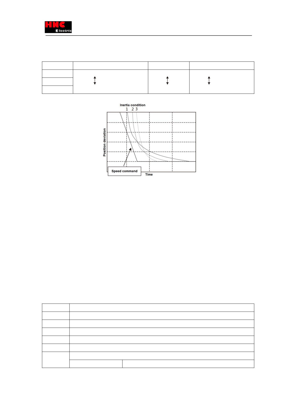
2: Standard setting
3: Applicable for the device that needs to adjust the light load(emphasis on convergence)
Table 8.8.2 The correspondence between the setting value of inertia condition and characteristics
Setting value
Stability of the corresponding load change
Convergence rate
Position deviation at constant speed
1
Strong
Slow
Small
2
3
Weak
Quick
Large
Figure 8.8.1 Convergence difference of position deviation by inertia condition
②Selection of control gain set
■Parameter No.113.0(position control) and No.129.0(speed control)
Control gain set is to change the parameter of control gain 1, control gain 2 and integral gain simultaneously.
If the setting value is larger, the traceability of corresponding command gets better, the interference response gets higher, and
the setting time gets shorter. If the setting value is too large, the servo may vibrate. Adjust the response correspondingly in the
condition that the servo does not vibrate. Set the smaller setting value in the beginning, then increase the value slowly while
confirm the operation.
For models of 750W or less, select from 10, 20,30.
For models of 1kW or more, select from 5,10,15.
③Auto tuning mode
■Parameter No.110.0
Select 1(standard mode) in the condition that there’s no unbalance in the horizontal axis. Select 2 (Unbalanced mode) when
there’s the unbalance.
■Procedures for auto tuning
Table 8.8.3 Procedures for auto tuning
Steps
Operation
1
Make sure all the wiring is correct.
2
Supply the control power to the drive (Note 1)
3
Power ON the main circuit of the dive(200VAC)
4
The SVON input of the drive is ON, the motor starts excitation. (I1 and COM - are connected)
5
The motor operates at the low speed according to the command pulse output by the upper controller.
6
Please follow the methods below to auto tuning.
■Methods by set panel
[Table 8.8.4 auto tuning (by set panel)]
Note 1: The control power supply for the models of 750W or less are supplied by external 24V DC. 1kW or more are supplied
from internal. So the control power supply of models of 1kW or more can be ON or OFF by switching on or cutting off the main
127
circuit AC power.
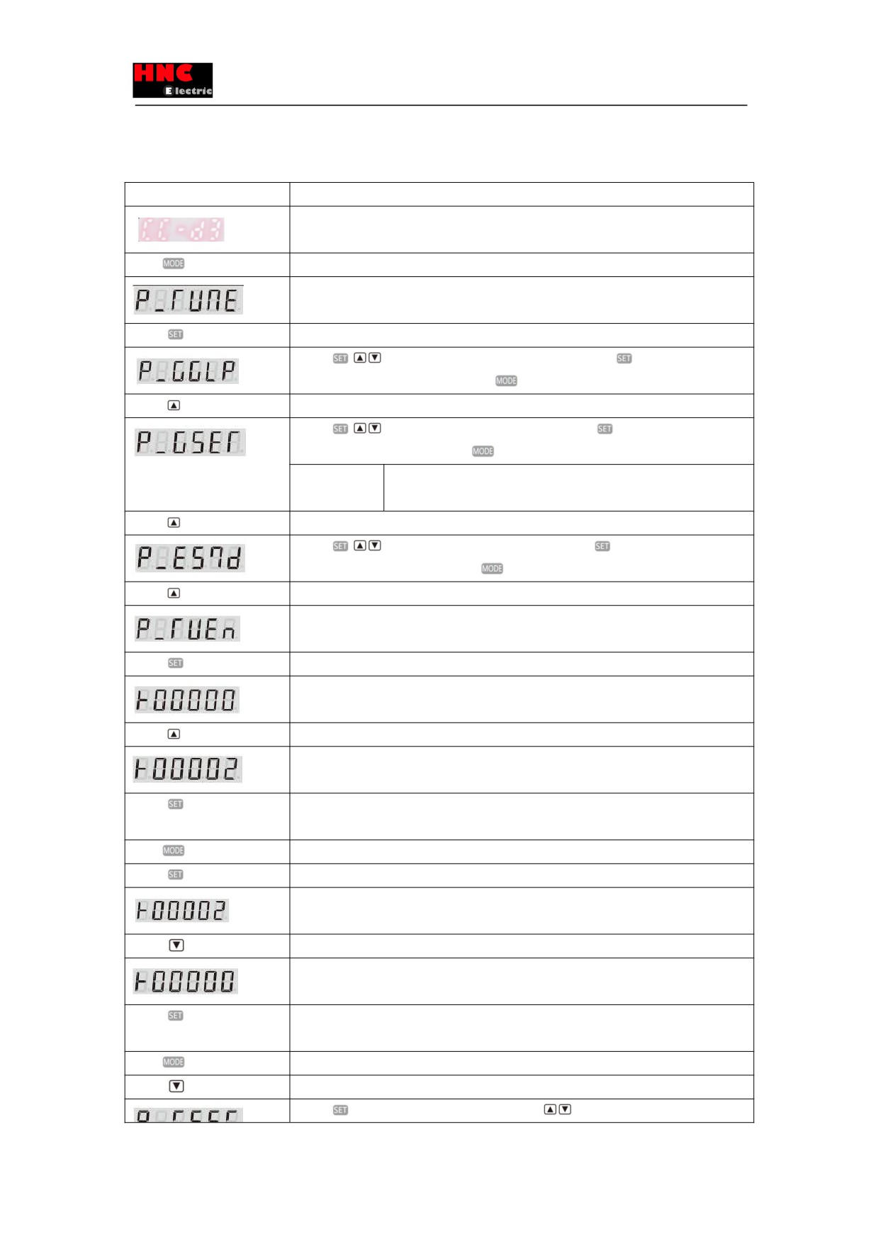
■By set panel
Table 8.8.4 Auto tuning (By set panel)
Display and operation
Description
Initial display.
Press
for five times
Switch to the set panel.
Switch to the auto tuning mode
Press
once
Enter into the auto tuning mode
Press
,
button to change the inertia condition. Press the
button to set the inertia
condition(from flicker to ON). Press the
button to return.
Press
once
Parameter display change.
Press
,
button to change the control gain. Press the
button to set the control
gain(from flicker to ON). Press the
button to return.
Points to note
At adjustment, if vibration occurs, decrease the setting value to no
vibration.
Press
twice
Parameter display change.
Press
,
button to change the auto tuning. Press the
button to set the auto
tuning(from flicker to ON). Press the
button to return.
Press
once
Parameter display change.
Selection whether to use of real-time auto tuning
Press
once
Selection whether to use of real-time auto tuning
Display the setting value of the parameter.
Initial value:”0”. The digit that can be changed will flicker.
Press
twice
Press the UP button to change the setting value.
“2”=Select [inertia ratio + damping ratio]
Press
once
When the parameter is set to drive RAM, the digit will change from flicker to ON.
Auto tuning begins at the same time.
Press
once
Return to the parameter selection.
Press
once
Display the setting value of Selection whether to use of real-time auto tuning
Display the setting value of the parameter.
Setting value:2. The digit that can be changed will flicker.
Press
once
Press the DOWN button to change the setting value.
Select “0” = [Disable real-time auto tuning]
Press
once
When the parameter is set to the drive RAM, the digit will change from flicker to ON.
Meanwhile, the auto tuning stops.
Press
once
Return to the parameter selection.
Press
three times
Change parameter display.
Press
to change the control gain level. Press
button to change the value. Press
128
the
button to set (from flicker to ON).
Points to note
To get the desired response, set the control gain level again.
Press
twice
Auto tuning completed and switch to the set panel mode.
Switch to parameter saving mode.
Press
once
The parameter is stored to EEPROM. ([P] in [SAVE_P] will flicker.)
Normal completion.
8.8.2 Fine tuning
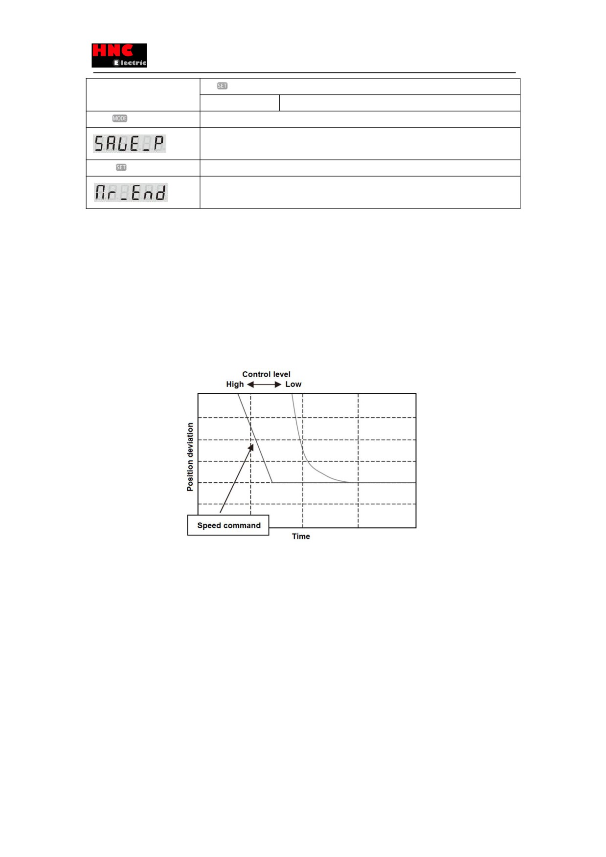
①Control level adjustment
The adjustment method of control level(position control) No.114.0 is shown below.
Control level is the parameter that the combination of control gain 1 and control gain 2 changed.
Increasing the control level can help to get better command traceability and shorten the setting time. And the response has
also improved. If higher, vibration may occur. Please adjust it to the required response in the absence of vibration.
Furthermore, overshoot occurs if set the higher [Gain FF compensation 1 (Position control)(No.117.0)] and improve the control
level. To avoid the overshoot, adjust the control level after reducing the [Gain FF compensation 1 (Position
control)(No.117.0)] .
Figure 8.8.3 Position deviation convergence difference set by control level
②Integral gain adjustment
The adjustment method of [Integral gain (position control)(Parameter No.119.0) is shown below.
Increasing the integral gain can reduce the influence to the convergence caused by friction or load change and shorten the
setting time. But if higher, vibration may occur. Please adjust it to the required response in the absence of vibration.
129
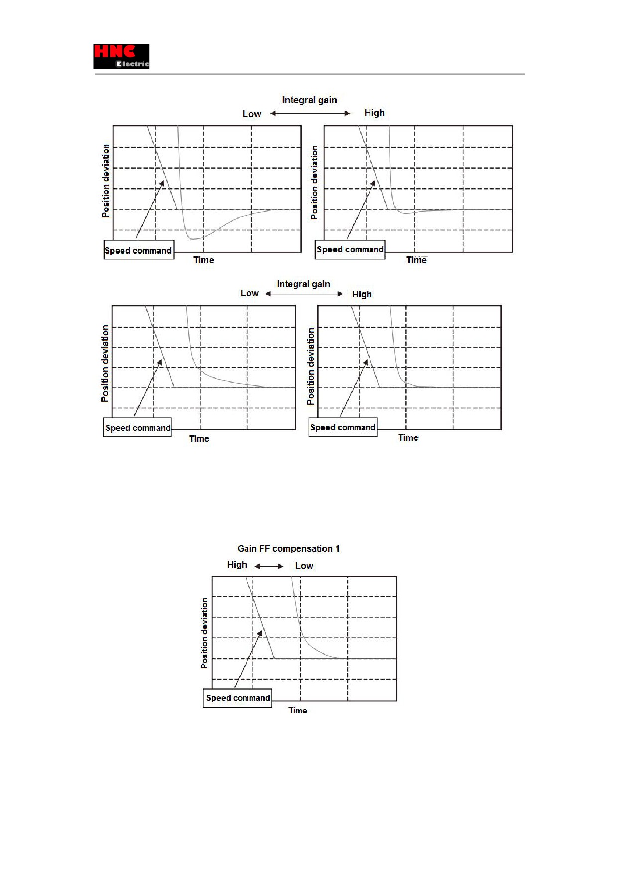
Figure 8.8.4 Position deviation convergence difference set by integral gain
③Gain FF compensation 1 adjustment
The adjustment method of Gain FF compensation 1(Position control) No.117.0 is shown below.
If the Gain FF compensation 1 is higher, the setting time is shorter. But if too high, overshoot may occur. Please adjust it to the
required response in the absence of overshoot.
Figure 8.8.5 Position deviation convergence difference set by Gain FF compensation 1
④Gain FF compensation 2 adjustment
The adjustment method of Gain FF compensation 2(Position control) No.118.0 is shown below.
Please set the correct inertia ratio. If the setting value is 10000, the position deviation is least. If the value is more than 10000,
130
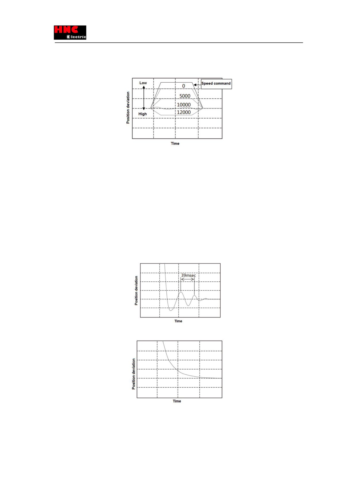
the position deviation will be on the negative side(over compensation).
If set the bigger value at lower resolution, the operation noise will become louder. If the position deviation in the operation has
no any other problems, the setting value can be 0.
Figure 8.8.6 Position deviation convergence difference set by Gain FF compensation 2
8.8.3 Vibration reduction adjustment
①Vibration reduction methods for smoothing filter
The adjustment method for [Position command smoothing filter 1(No.66.0)] and [Position command smoothing filter 1 Moving
average order(No.80.0)] are shown below.
Set the [Position command smoothing filter 1(No.66.0)] to “1” and set the [Position command smoothing filter 1 Moving
average order(No.80.0)] to the value calculated by the cycle time of vibration. The bigger the value is, the longer the command
delay time is.
Formula: Parameter No.80.0 setting value=Vibration cycle time [s] ×6, 250(750W or less)
Parameter No.80.0 setting value=Vibration cycle time [s] ×5, 000(1Kw or more)
In this example, the vibration cycle time is 39ms, and the average order is 6250×0. 039=243.
The delay tie is 243×0. 16ms=38. 88ms.
Figure 8.8.7 Before Position command smoothing filter 1 setting
Figure 8.8.8 After Position command smoothing filter 1 setting
②Vibration reduction methods for notch filter
The adjustment method for torque command notch filter No.160.1, 168. 0、169. 0.170. 0 are shown below. Set the [Torque
command Selection of whether to use notch filter(No.160.1)] to “1” and set the vibration frequency in the [Torque command
Notch filter frequency(No.168.0)]. The vibration frequency is calculated from the waveform such as the torque command when
131
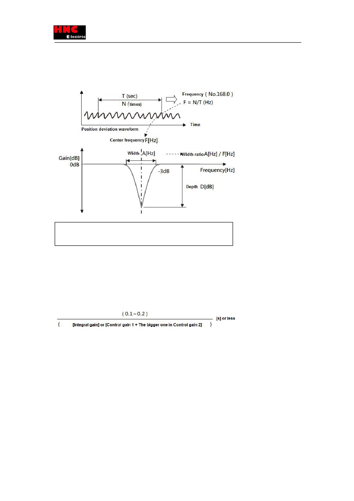
the vibration occurs.
When the gap is too big, even if setting the notch filter, the resonance cannot be suppressed completely. At this time, increase
the [Torque command Notch filter depth selection(No.170.0)] to get the shallower filter performance. When multiple notch
frequency exist, increase the [Torque command Notch filter width selection(No.169.0)] to widen the notch frequency.
Width ratio=[ Torque command Notch filter width selection(No.169.0)]
×0. 125
Depth ratio=[ Torque command Notch filter depth selection(No.170.0)] /256
③Vibration reduction methods for low-pass filter
The adjustment method for torque command low-pass filter No. 160. 0、162. 0 are shown below.
Set the [Option for Torque command low-pass filter(No. 160. 0) to “1”(Enable). The default value is “1”(Enable) at factory
shipment. Increasing [Torque command preliminary filter time constant for Low-pass filter(No. 162. 0)] can help to suppress
the resonance. But if increase too much, it will cause some other vibration.
The maximum value is based on the following formula.
8.9 Home position return
8.9.1 Overview
The home position return is the operation of coordinating the command and mechanical coordinates within the drive. When
using the positioning function in the drive, perform the home position return according to the actual needs.
■Using incremental system
Home position return must be done when power-ON.
■Using absolute system
The encoder battery backs up after power OFF. So when the home position return is performed once in installation, there’s no
need to have the home position return after power ON again
When using the positioning function in the drive, perform the home position return according to the actual needs.
8.9.2 Wiring and basic setting
132
For the wiring and basic parameter setting, refer to [Appendix 2 SV-E3 Positioner function].
■In home position return, there are Arbitrary position, Stopper and Home position DOG front end and used in the situation of
selection of Z-phase as the base signal.
■The home position return can be started by user I/O input.
■If perform the home position return by Home position DOG front end, please use the user I/O input.
8.9.3 Types and parameter by home position return
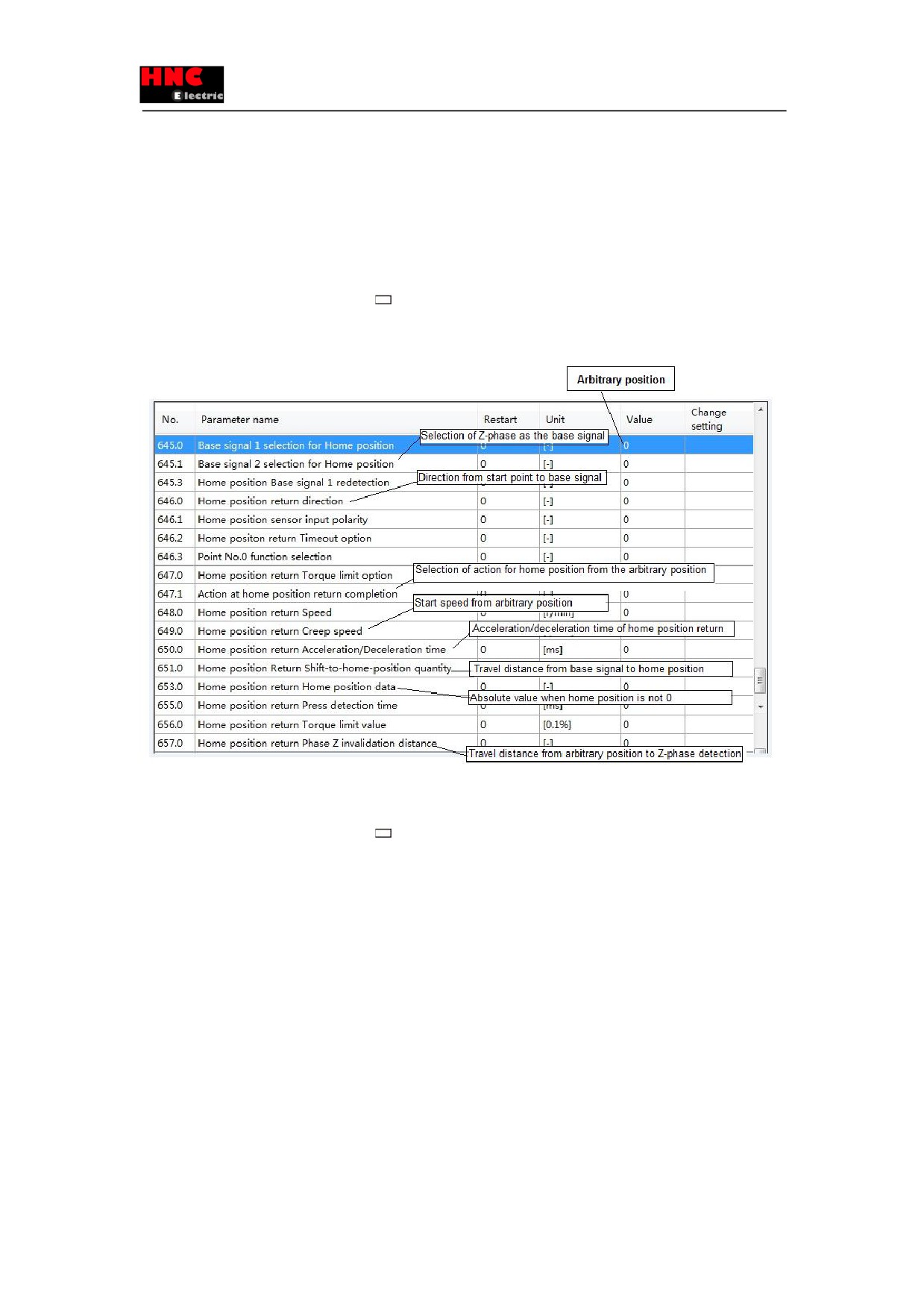
1) Arbitrary position
Use the following parameter items in the box
when use the arbitrary position as the base signal.
For the details of parameters, refer to [8.9.4 Parameter description].
For the examples of parameter setting method, refer to [8.9.8 Parameter description for home position return].
Figure 8.9.1
2) Stopper
Use the following parameter items in the box
when use the stopper.
For the details of parameters, refer to [8.9.4 Parameter description].
For the examples of parameter setting method, refer to [8.9.8 Parameter description for home position return].
133
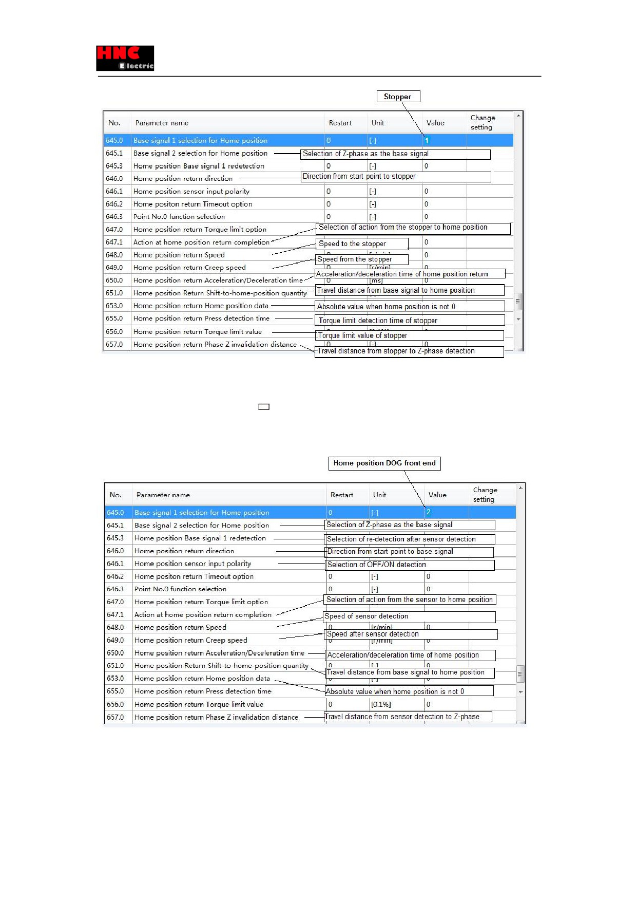
Figure 8.9.2
3) Home position DOG front end (home position sensor)
Use the following parameter items in the box
when use the Home position DOG front end.
For the details of parameters, refer to [8.9.4 Parameter description].
For the examples of parameter setting method, refer to [8.9.8 Parameter description for home position return].
Figure 8.9.3
8.9.4 Parameter description
The home position return can be done by the combination of parameter setting.
The home positon return is specified by the following combination of parameters.
・ No. 645. 0: Base signal 1 selection for Home position
134
・ No. 645. 1: Base signal 2 selection for Home position
・ No. 645. 3: Home position Base signal 1 redetection
・ No. 646. 0: Home position return direction
・ No. 647. 1: Action at home position return completion
No.
Name
Unit
645. 0
Base signal 1 selection for Home position
-
Select Base signal 1 at determine Home position
0 = Arbitrary position
1 = Stopper
2 = Home position DOG frond end [Initial value]
Take the Encoder Phase Z nearest to the current position as the base signal, set the parameter to “Arbitrary position”. Set the
Base signal 2 selection for Home position (No. 645. 1) to “Encoder Phase Z”.
No.
Name
Unit
645. 1
Base signal 2 selection for Home position
-
Set another base signal(Base signal 2)for home position after detecting Base signal 1.
0 = None [Initial value]
1 = Encoder Phase Z
When setting Base signal 1 selection for Home position(No. 645. 0) to “Home position DOG frond end” and setting Base signal
2 selection for Home position to “Encoder Phase Z”, after detecting the Home position DOG front end, move the Home
position return Phase Z invalidation distance(No.657.0), then set the Encoder Phase Z for the home position.
No.
Name
Unit
645. 3
Home position Base signal 1 redetection
-
The selection of redetection can be done after returning in the [Home position return Creep speed] when the Home position
DOG frond end is detected by the Home position return Speed detection. To improve the detection accuracy of home position
base signal, set the Home position return Creep speed to a lower value.
0 = Disable (Initial value)
1 = Enable
Only applicable for the situation that setting the [Base signal 1 selection for Home position] to “2= Home position DOG front
end”.
If set to “1= Enable”, back and return to home position DOG front end after home position speed detects the home position
DOG front end. The home position creep speed detects the home position DOG front end.
The start point of home position return is judged by the internal or external of the home position sensor, which depends on
ORG signal of user input I/O in the home position return.
For details, refer to [8.9.5 Home position sensor exit]
135
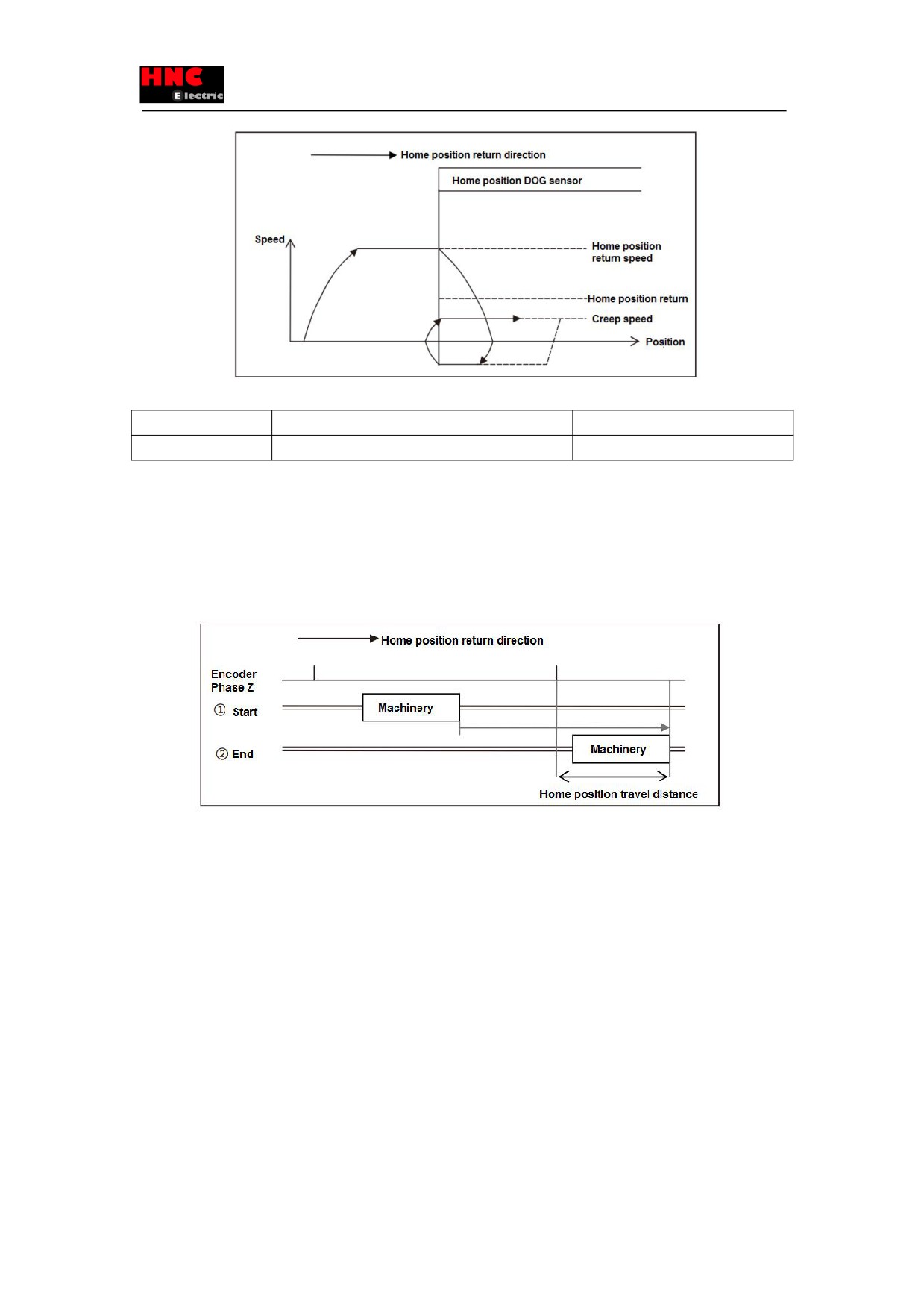
Figure 8.9.4 Home position Base signal 1 redetection
No.
Name
Unit
646.0
Home position return direction
-
Set Home position return base signal 1 direction
0 = CCW [Initial value]
1 = CW
1) Under the condition that home position base signal 1 is “Arbitrary position”.
When set the Base signal 2 selection for Home position to “1=Encoder Phase Z”, the operation direction of Encoder Phase Z
can be detected, that is the home position base signal moves in the direction of home position travel distance.
Figure 8.9.5 Home position return direction (Arbitrary position)
2) Under the condition that home position base signal 1 is “Stopper”.
The operation direction that the home position return starts.
When the Base signal 2 selection for Home position is set to “1=Encoder Phase Z”, the direction is opposite to the one of the
encoder phase Z detection. Figure 8.9.6 is the example to set the home position travel distance after detecting Phase Z. The
direction of moving home position travel distance from home position base signal is opposite. The home position return
direction from ① Start (home position return starts) is opposite to ②Stopper is opposite to the direction from ② to ③ End
(home position return completion).
136
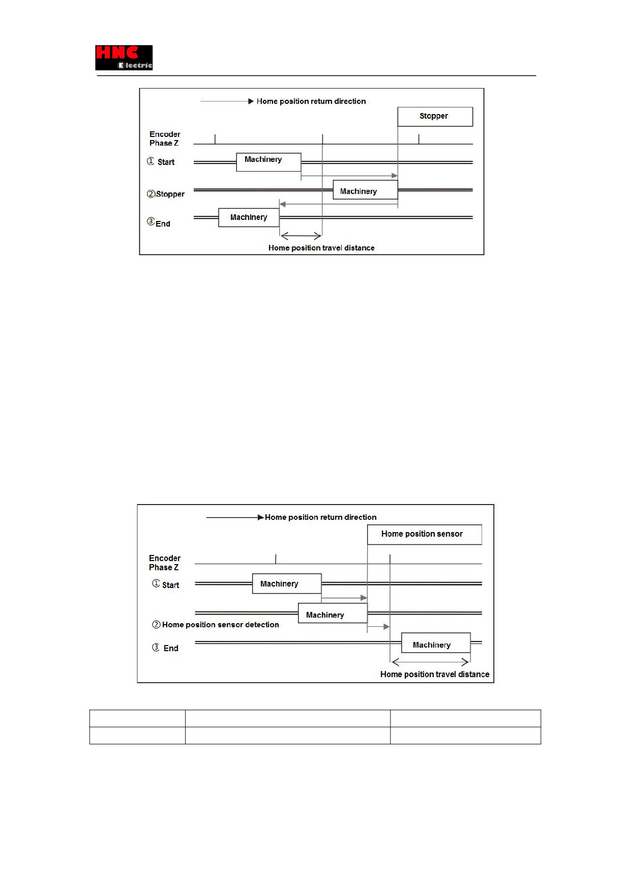
Figure 8.9.6 Home position return direction (Stopper)
3) Under the condition that home position base signal 1 is “Home position DOG frond end ”.
Set the direction from Home position DOG sensor front to Home position DOG front end.
If the start point of home position return is in the front of home position DOG sensor, it is the operation direction after home
position return starts. If the start point is inside the home position DOG sensor, it moves automatically in the opposite direction
of home position return. When it moves out from the home position DOG sensor, the home position DOG front end can be
detected.
When the Base signal 2 selection for Home position is set to “1=Encoder Phase Z”, the direction is same to the encoder phase
Z detection direction.
Figure 6.9.4 is the example of setting home position travel distance after detecting phase Z. The direction from home position
base signal to home position travel distance should be set here, as the start point of home position return is inside the home
position sensor. That is the direction from ①Start(home position start) to② Home position sensor detection (Home position
DOG front end detection), and from ② to ③End (Home position return completion).
The direction from home position base signal to home position travel distance.
Figure 8.9.7 Home position return direction (home position DOG front end)
No.
Name
Unit
646.1
Home position sensor input polarity
-
Set Home position sensor input polarity by user I/O ORG
0 = When OFF, detect Home position dog front end [Initial value]
1=WhenON,detectHomepositiondogfrontend
137
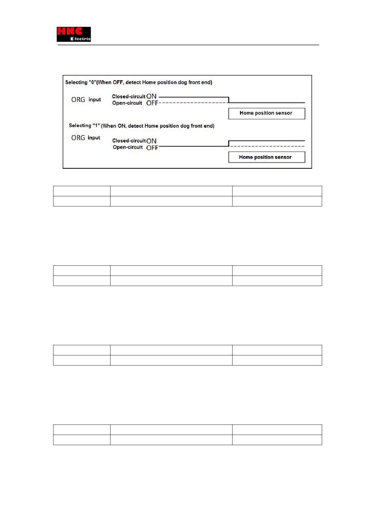
Selecting “0”, detect the home position sensor at open-circuit between ORG and COM-.
Selecting “1”, detect the home position sensor at closed-circuit between ORG and COM-.
Figure 8.9.8 Home position sensor input polarity
No.
Name
Unit
646.2
Home positon return Timeout option
-
Enable/Disable Home position return Timeout.
0 = Disable
1 = Enable [Initial value]
The function corresponds to collision.
When selecting “1 =Enable”, count the elapsed time after home position return starts. If exceeding the home position return
timeout(No.659.0), alarm of “Position command overflow/home position return failure” occurs and make the servo disconnect.
No.
Name
Unit
646.3
Point No.0 function selection
-
Selecting Point No.0 and function of inputting user I/O CW start PCSTART1.
0 = Return to home position [Initial value]
1 = Point table operation
Set “0 = Return to home position”, the home position return starts.
Set “1 = Point table operation”, the operation of Point No.0 starts.
This parameter is used to start the home position return when there’s no home position input HOME in I/O.
No.
Name
Unit
647.0
Home position return Torque limit option
-
This is the safety function against the collision in home position return.
Enable/Disable Home position return Torque limit. Set the home position return torque limit value in Parameter No.656.0.
0 = Disable [Initial value]
1 = Enable
But, when selecting “Stopper” in base signal 1 for home position(No. 645. 0), it is not relevant to this setting. Torque limit value
to the stopper is the Home position return Torque limit value(No. 656. 0).
No.
Name
Unit
647.1
Action at home position return completion
-
Select an action at home position return completion.
0 = No move [Initial value]
1 = Move
When selecting “No move”, after detecting the base signal for home position, deceleration to stop and home position return
138
completed.
When selecting “Move”, after detecting the base signal for home position, deceleration to stop and perform the positioning
operation according to the parameter set.
No.
Name
Unit
648.0
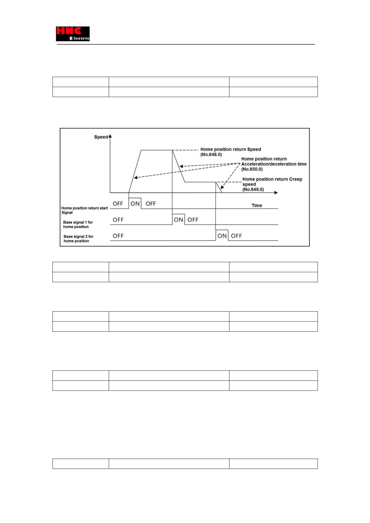
Home position return Speed
rpm
Set Home position return Speed.
[Setting range] 1 to max. speed of the motor
[Initial value] 500
Figure 8.9.9 Home position return Speed
No.
Name
Unit
649.0
Home position return Creep speed
rpm
Set Creep speed after Home position Base signal 1 detection.
[Setting range] 1 to max. speed of the motor
[Initial value] 10
No.
Name
Unit
650.0
Home position return Acceleration/deceleration time
ms/1000rpm
Set Acceleration/Deceleration time for Home position return.
Set the acceleration time from speed 0 to 1000rpm and deceleration time from 1000 to 0rpm.
[Setting range] 0~5, 000
[Initial value] 30
No.
Name
Unit
651.0
Home position Return Shift-to-home-position quantity
Command unit(Note 1)
Set shift quantity from the position where the Base signal was detected to the home position.
In the situation except “1: Stopper” in home position base signal 1(No. 645. 0), the base signal begins to shift to the home
position(No. 646. 0). The home position returns according to the shift quantity(No. 646. 0).
If “1: Stopper” in home position base signal 1 is set, the direction between shift-to-home-position and home position return(No.
646. 0) is opposite.
[Setting range] 0~1, 000, 000, 000
[Initial value]
0[command unit]
No.
Name
Unit
139