SERVO DRIVE SV-E3 SERIES. INSTRUCTION MANUAL (v1.5) - page 9

■Troubleshooting 4 (Motor operation is not steady)
The motor operates unsteadily.
Table 9.3.4
Cause
What to do
FG and GND connection is wrong.
Connect FG and GND correctly.
Speed and position command is not steady.
Check the contact of cables and connectors.
Misadjustment
Adjust the parameters.
The motor rotate without host command input.
Set the appropriate values for No.33.0 「Pulse train command - Input filter
selection」in position control mode.
Adjust parameter No.60.0 「Analog speed command
- Fixed offset
value」 in speed control mode.
Adjust parameter No.300.0 「Analog torque command Fixed offset value」
in torque control mode.
Command is interfered.
The shielded twisted-pair cable is used for I/O cable in a vulnerable
environment. So is the encoder cable. The encoder cable should be 20m
or less.
Position deviation occurs.
Set the appropriate values for No.33.0 「Pulse train command - Input filter
selection」in position control/pulse train command mode. Check whether
the pulse output of host control device (such as PLC) is beyond the limit
value. Check whether the product of ①No.33(Pulse command
input(position) and host control device output, ②No.65(Position
command) and No.67(Position feedback), ③No.67 and parameter
No.276.0/278.0(Encoder pulse output division and multiplication) is
consistent with the position feedback of host control device. If inconsistent,
it may be interfered. Then connect FG correctly and adjust parameter
No.33.0.
Please use shielded twisted-pair for I/O cable.
Deviation occurs when home position reset.
Check the command input of host control device. Check whether to get the
Z-phase correctly from the host control device. If the Z-phase pulse
amplitude is small, adjust No.276.0 and 278.0 「Encoder output division
and multiplication」to increase the pulse amplitude.
■Troubleshooting 5(Vibration and sound)
Vibration and sound occurs when the motor operates.
Table 9.3.5
Cause
What to do
Large gain
Adjust the gain.
The machine or devices loosen.
Check the installment of motor, reducer and coupling.
Interference occurs.
Check the cables’ length and shielding.
The high-voltage cable(motor power cable) should be isolated from the
signal cable (encoder cable).
Resonance occurs between motor and device.
Adjust position command smoothing filter at low-vibration; Adjust low-pass
filter or notch filter at high-vibration.
160
The drive and motor do not match.
If the drive and motor do not match, clear the EEPROM parameter and
change the motor models.
Appendix
Appendix 1 Recommended wire/cable
Cable name
AWG
UL
Heat-resistance
Remark
Motor power cable (750W or less)
18
2517
105℃
Motor power cable (1KW or less)
14 Note 1)
2501
105℃
200VAC input (750W or less)
18
1015
105℃
FG cable Note 2)
200VAC input
(1KW or more)
14 Note 1)
1015
105℃
FG cable Note 2)
Encoder
Power:22
20276
80℃
Max.20m for shielded cable of 5P(10
Signal:24
cores) (when using shielded
twisted-pair cable)
User I/O
26
1007
80℃
Shielded twisted-pair cable
Recommended length: 50m or less
Regenerative resistor connection
18
1015
105℃
Brake
18
2517
105℃
1P(2 cores)
Main circuit DC power (750W or
18
1015
105℃
less) Note 2)
Main circuit DC power (1KW or
14 Note 1)
1015
105℃
more) Note 2)
Communication between the drives
28
20539
80℃
Ribbon cable 10 cores
Note 2)
Accessories ((2.54mm spacing)
The length of cable depends on the actual situation.
Note 1) AWG16 cable can be used for 1kW motor.
Note 2)For multi-axial drives
Appendix 2 SV- E3 positioner function
1. Overview
This product has the positioning function of using point table.
Preset the data by the point table in the drive and set the Point No. to be started through I/O input by the upper controller. After
inputting the start signal, the positioning will be done according to the selected Point No.
2. Basic setting
[2.1 User I/O connector (CN1) wiring]
Table 2.1 User I/O connector CN1 connector pins arrangements
Name
Symbol
Pin No.
Signal name
Contents
User I/O
CN1
1
24V
Drive control power supply 24V input
161

●24V power
2
G24V
Drive control power supply GND
supply input
3
COM+
I/O power supply 24V input
●Parallel I/O
4
I1
(SVON) Servo ON input
●Pulse train
5
I2
(RESET/PCLR)Alarm reset/ deviation counter clearing input
Command
6
I3
(PCSTART1)CW start input
input
7
I4
(PCSEL1)Point NO. 1 input
●ABZ output
8
I5
(PCSEL2) Point NO. 2 input
9
I6
(PCSEL3) Point NO. 3 input
10
I7
(PCSEL4) Point NO. 4 input
11
I8
(ORG)Home position sensor input
12
COM-
I/O power supply GND
13
O1
(MBRK) Brake release output
14
O2
(SERVO) Servo status output
15
O3
(MEND)Action completion output
16
O4
(HEND)Home position return completion output
17
O5
(T-LIMIT) Torque limit output
18
O6
(OCZ )Encoder Z-phase output (open collector)
19
O7+
(SRDY+) Servo ready output +
20
O7-
(SRDY-) Servo ready output -
21
O8+
(ALM+) Servo alarm output+
22
O8-
(ALM-) Servo alarm output-
23
NC1
Reserved (Disconnected)
24
SP1
Reserved
25
SP2
Reserved
26
CMD_PLS
Reserved
27
/CMD_PLS
Pulse command Pulse, orthogonal phase difference A-phase,
CCW
28
CC-P
Pulse command 24V of PLS
29
CC-D
Pulse command 24V of DIR
30
CMD_DI R
Reserved
31
/CMD_DI R
Pulse command Direction, orthogonal phase difference
B-phase, CW
32
A SPEED
Reserved
33
A_GND
Reserved
34
A_TRQ
Reserved
35
A_GND
Reserved
36
OUT_A
Encoder A phase output
162
37
/OUT_A
Encoder /A phase output
38
OUT_B
Encoder B phase output
39
/OUT_B
Encoder /B phase output
40
OUT_Z
Encoder Z phase output
41
/OUT_Z
Encoder /Z phase output
42
SG
Signal ground
43
485
RS-485 communication data
44
/485
RS-485 communication /data
45
SG
Signal ground
46
NC2
Reserved(Disconnected)
47
SP3
Reserved
48
SP4
Reserved
EDM+
49
Reserved
EDM-
50
Reserved
[2.2 Basic parameters setting]
Set the basic parameters.
The following parameters must be set if using the positioning function.
Table 2.2 Parameter of control mode change
Parameter No.
Parameter
Description
2.0
Select control mode.
Set to “0”.
3.0
Select command mode.
Set to “3”.
Selection method for different operation modes.
Table 2.3
Operation modes
Internal position command
Selection of operation
Starting method
Selection of operation modes
modes
(No. 642. 0)
(No. 9. 0)
Point table
0
0
I /O input(PCSTART1)
Manual pulse input
2
Arbitrary
I /O input(pulse command input)
[2.3 User I/O description]
The user I/O related to the positioning function are shown below.
■Input
ON when connection with COM- is close; OFF when open.
1) PCSEL1. . . 4 Point NO. selection
・Specify the Point No. and home position return to be started
・Select home position return or Point No.0 for starting Point No.0 according to the setting 「Point No.0 function selection(No.
646. 3).
Table 2.4
PCSEL4
PCSEL3
PCSEL2
PCSEL1
Description
163

OFF
OFF
OFF
OFF
Home position return or Point No.0
OFF
OFF
OFF
ON
Point No.1
OFF
OFF
ON
ON
Point No.2
OFF
OFF
ON
ON
Point No.3
---
---
---
---
------
OFF
ON
ON
ON
Point No.7
---
---
---
---
------
ON
ON
ON
ON
Point No.15
2) PCSTART1 CW start
・The action and home position return of Point No. can be specified when the connection with COM- from OFF to ON.
・When set the 「Point No.0 function selection」(No. 646. 3)to “0= Return to home position” and specify 0 to the Point No.,
the home position return can be started by inputting PCSTART1.
3) ORG home position sensor
・Input the home position sensor signal at home position return by home position sensor.
For details, refer to 「8. 9 Home position return」.
4) HOME position return start
・Set the input signal of “Position control/internal generation command dedication 1” to the special I/O. About the special I/O
setting, refer to 「Appendix 3 SV-E3 special I /O setting」.
・The home position return starts when the connection with COM- from open-circuit to close-circuit.
■Output
ON when connection with COM- is close; OFF when open.
1) MEND completion
・If the action of Point table and home position return completed and ready for the next operation, it will become close-circuit.
・OFF when the operation from starts to pauses.
・Make sure the MEND is close-circuit before inputting PCSTART 1. The start command will be ignored when MEND is
open-circuit.
・It is open-circuit at servo OFF.
2) HEND home position return completion
・Close-circuit when home position return completed
・When the command method is absolute, home position return must be done if HEND is open-circuit.
・For details, refer to 「8. 9Home position return」.
3) P M1. . . 3 Point No. output
・Set the input signal of “Position control/internal generation command dedication 1” to the special I/O. About the special I/O
setting, refer to 「Appendix 3 SV-E3 special I /O setting」.
・Point No. that output starts or ends
・Select the Point No. output time and description in 「Point No. output method」(No. 644. 0).
・Open-circuit (Point NO.0) at servo OFF and home position return after power ON to the drive.
Table 2.5
PM3
PM2
PM1
Description
OFF
OFF
OFF
Point No.0 and 8
OFF
OFF
ON
Point No.1 and 9
OFF
ON
OFF
Point No.2 and 8
OFF
ON
ON
Point No.3 and 7
164

---
---
---
---
ON
ON
ON
Point No.7 and 15
The running operation and dwell time of Point NO. output in 「Point No. output method」 are shown below.
Table 2.6
Point No.
Running operation
Dwell time
1
Continuous
0
2
Continuous
0
3
Single
Arbitrary value
3. Point table operation
[3.1 Point table data]
The Point table setting are shown below.
Table 3.1 Point table data
Items
Description
Unit
Setting range
Command
Absolute value: Take the position data as the target position
-
Absolute value and
method
Relative value: Take the travel distance from current position to target
relative value
position as the position data
Running
Single: Executing the selected one Point No.
-
Single, continuous
operation
Continuous: Execute the next Point No. continuously
Position
1)Select absolute value according to command method
[Command
-1, 073, 741, 823
Set the target position
unit]
~ 1, 073, 741, 823
2) Select relative value according to command method
Set travel distance. Positive value: CCW rotation
Negative value: CW rotation
Speed
Set the motor speed at positioning. And the setting value must not be
[ rpm]
1~ max.speed of the
outside the max. speed of the motor.
motor
Acceleration
Set the acceleration time for the motor, that is the time from 0rpm to
[ms/
0~5000
time
1000rpm
1000rpm]
Deceleration
Set the deceleration time for the motor, that is the time from 1000rpm
[ms/
0~5000
time
to 0rpm
1000rpm]
Dwell time
Set the dwell time for pause after the positioning completion has been
[ms]
0~20, 000
detected by Point no. positioning completion (range). Execute the
position command for the next Point No. after the dwell time. When
set the running operation to 「Continuous」,the dwell time is 「0」 and
the next Point No. continues.
Positioning
Set the position deviation value to determine positioning completion.
[pulse]
0~32, 767
completion
The dwell time begins after the position command completed
specified by the Point No. and the position deviation is within the
setting range. The unit is same to the encoder pulse unit.
Valid/ invalid
Set the valid or invalid to the operation. When set the operation to
-
Valid/ invalid
invalid, the Point No. will not execute until the next valid Point No.
[3.2 Command unit setting]
165
The command unit is the unit used for position and distance between upper controller and drives. The mini. Command unit is 1.
The function of command division and multiplication is to change the position data from command unit to encoder pulse unit.
Set the command division and multiplication b「command division and multiplicatio(Numerator)」No. 34. 0)and 「command
division and multiplicatio(Denominator)
No. 36. 0).Save the parameters if the command division and multiplication changes
and execute the home position return after the power ON again.
Make sure the range for the ratio of command division and multiplication is 1 to 1000. (In pulse command mode, the range is 0.
001 to 1000).
[3.3 Operation range for position and position command overflow detection]
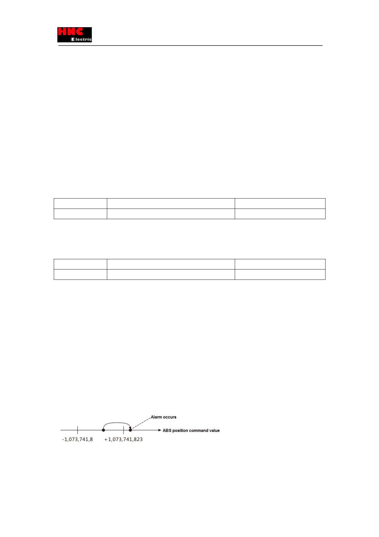
The operation range for position (ABS position command) of Point table:
Absolute position: -1, 073, 741, 823~+1, 073, 741, 823 [command unit]
Whether the「Position command overflow/ home position return failure」alarms or not, after the position of Point table (ABS
position command value) exceeds the range described above, can be selected by「Internal speed command - Overflow
detection option」(No. 643. 0). When set it to “0=Disable”, the absolute value cannot be specified to the command method. For
details, refer to「Parameter description Internal speed command - Overflow detection option」.
[3.4 Parameter description]
No.
Name
Unit
642. 0
Internal speed command - Operation mode
-
Set Operation mode for internal position command.
0 = Point Table
1 = Communication operation
2 = Manual pulse input
No.
Name
Unit
643. 0
Internal speed command - Overflow detection option
-
Enable/Disable Internal position command Overflow detection function
0 = Disable
1 = Enable (Initial setting)
The function of Internal speed command - Overflow detection option is to prevent the target position of Point table and
communication operation(test run) exceeding the absolute position range to make the absolute position disappear. If the target
position (ABS position command value) exceeds absolute position range(-1, 073, 741, 823~+1, 073, 741, 823), here can be
set for「Position command overflow/ home position return failure」to alarm or not.
Set it to “0= Disable” when outside the absolute position range and have the relative position command to the same direction
repeatedly.
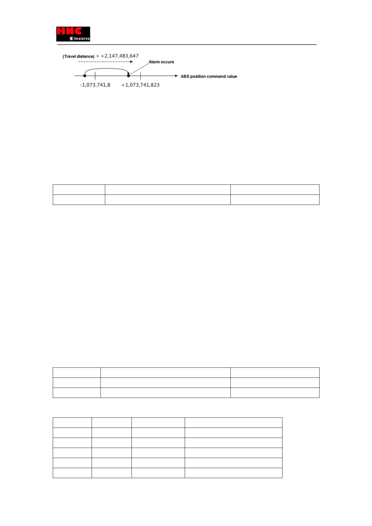
■Conditions for alarm occurrence
1)Set to “1=Enable”
The alarm occurs when the target position of ABS position command value exceed the range of -1, 073, 741, 823~+1, 073,
741, 823.
The alarm occurs when the ABS position command value exceeds the range of -1,073,741,823 to +1,073,741,823 after servo
On and the travel distance exceeds the range of -2,147,483,647 to +2,147,483,647.
166
2)Set to “0=Disable”
In the relative command, no alarm occurs even if the ABS position command value exceeds the absolute position range. But
alarm occurs in the absolute command.
The alarm occurs when “Absolute value” exist in the command method of Point table.
■Time for alarm occurrence
No alarm occurs when the ABS position command value exceed absolute position range at servo ON.
The alarm occurs when the operation starts in a single operation setting.
In the continuous operation setting, after the operation starts, the alarm occurs before the Point No. of which the ABS position
command value exceeds the range.
No.
Name
Unit
644. 0
Point No. output method
-
Set Point No. output method to the user I/O PM1. . . 3.
0 = Output Operation start point at Operation start
1 = Output Operation start point at Operation end
2 = Output each point No.at each operation start
For details, refer to 「2-3 User I/O description PM1. . . 3 Point No. output」
Appendix 3 SV- E3 special I/O setting
1. Preface
The parallel I/O setting changes automatically after setting the control mode and command mode for the drive.
2. Special I/O setting
The parallel I/O can be set specially based on the control mode and command mode. The setting are shown below. There is
only the default I/O setting when no special settings.
[2. 1 Position control mode(pulse command input)]
As shown in Table 3.1 to set the parameters and Table 3.2 to set the special I/O.
For signal details, refer to 「8.7.1 Signal description」.
Table 3.1 Parameter setting at position control mode(pulse command input)
Parameter No.
Parameter
Description
2.0
Select control mode.
Set to “0”.
3.0
Select command mode.
Set to “1”.
Table 3.2 Special I/O setting(dedication 1) at position control mode(pulse command input)
Pin No.
Signal name
Description
Function
4
I1
SVON
Servo ON
5
I2
RESET
Alarm reset
6
I3
HOLD
Command input restriction
7
I4
PCLR
Deviation counter clearing
8
I5
HOME
Home position return start
167
9
I6
CCW
CCW drive restriction
10
I7
CWL
CW drive restriction
11
I8
TLSEL1
Torque limit selection 1
47
I9
Reserved
13
O1
MBRK
Break release
14
O2
SERVO
Servo status output
15
O3
POSIN
Positioning completion output
16
O4
Reserved
17
O5
HEND
Home position return completion
18
O6
MEND/T-LIMIT
Operation completion/ torque limit
19
O7
OCZ
Encoder phase Z output
21
O8
SRDY
Servo ready
48
O9
ALM
Alarm status
[2. 2 Position control mode(internal position command)]
As shown in Table 3.3 to set the parameters and Table 3.4 to set the special I/O.
For signal details, refer to 「8.7.1 Signal description」.
Table 3.3 Parameter setting at position control mode(internal position command)
Parameter No.
Parameter
Description
2.0
Select control mode.
Set to “0”.
3.0
Select command mode.
Set to “3”.
Table 3.4 Special I/O setting(dedication 1) at position control mode(internal position command)
Pin No.
Signal name
Description
Function
4
I1
SVON
Servo ON
5
I2
RESET/PCLR
Alarm reset/deviation counter clearing
6
I3
PCSTART1
CW start
7
I4
PCSEL1
Point No.1
8
I5
PCSEL2
Point No.2
9
I6
PCSEL3
Point No.3
10
I7
HOME
Home position return start
11
I8
TLSEL1
Torque limit selection 1
47
I9
Reserved
13
O1
PM1
Point No. 1 output
14
O2
PM2
Point No. 2 output
15
O3
PM3
Point No. 3 output
16
O4
Reserved
17
O5
HEND
Home position return completion
168
18
O6
MEND/T-LIMIT
Operation completion/ torque limit
19
O7
OCZ
Encoder phase Z output
21
O8
SRDY
Servo ready
48
O9
ALM
Alarm status
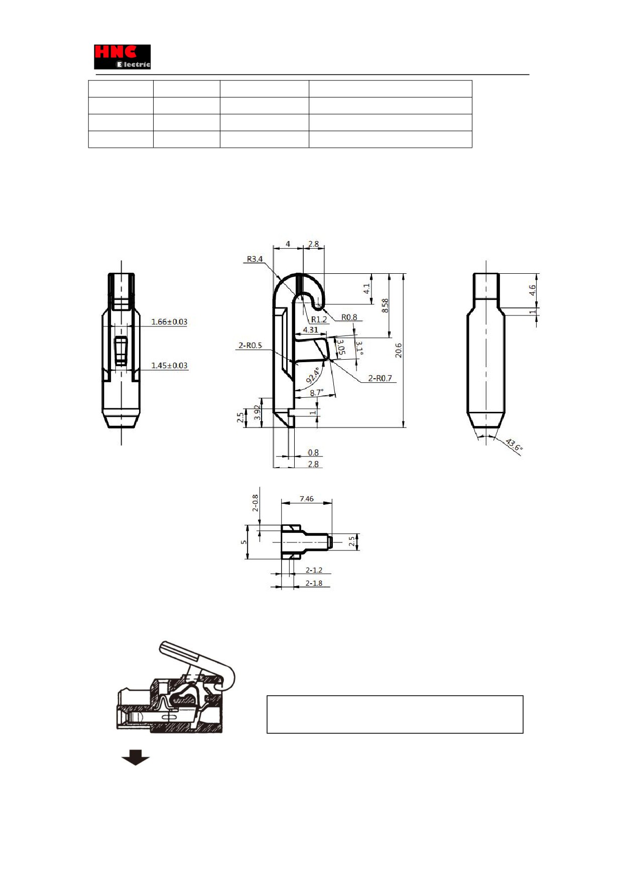
Appendix 4 Servo drive power connector (L1/ L2/ B1/B2, U/ V/ W)wiring
Use the crowbar packed with the servo while wiring.
1)The crowbar is packed with the power connector at shipping
2) Cable connection procedures
1) Attach the crowbar to the handling slot on the upper portion
(removable)
169
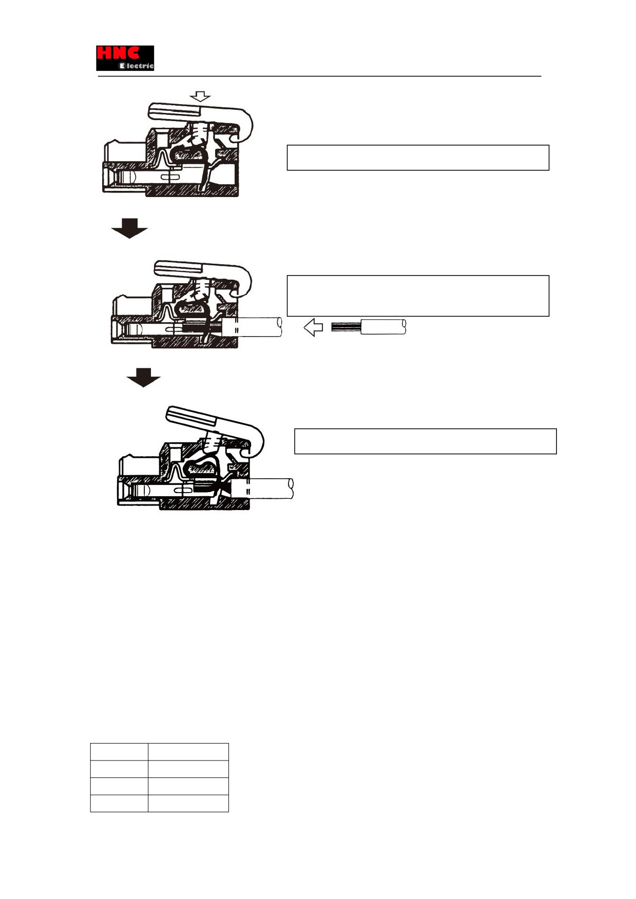
2) Press down the crowbar to push down the spring.
3) Insert the peeled cable while pressing down the lever, until it hits
the insertion
4)Release the crowbar.
Appendix 5 SV-E3 series absolute system description
1. Overview
This product constitutes the absolute system by using the unique magnetic absolute encoder. Have the encoder clearing after
home position return and no need for home position return when restarting the power supply.
The following procedures are ready for the absolute system:
①Use the motor equipped with the absolute encoder and drive with absolute specifications
②Connecting the encoder battery.
③The upper controller can get the absolute data by RS-485.
2. Applicable models
Use the following motor and drive combination when using absolute system.
Table 1 Applicable motor and drive
Output
Drive
50W
SV-E3P005A2-A
100W
SV-E3P010A2-A
200W
SV-E3P020A2-A
170

400W
SV-E3P040A2-A
750W
SV-E3P075A2-A
1KW
SV-E3P100A2-A
1.5KW
SV-E3P150A2-A
2KW
SV-E3P200A2-A
3. Setting
[3.1 Setting for absolute system]
■Parameter setting is needed for absolute system of the drive.
■Change the Selection of an encoder system (No.257.0) from 0 (initial setting, incremental system) to “1(absolute system).
This can be set by the set panel.
■Refer to 「5 Absolute encoder initialization」 for the operation procedures.
[3.2 RS-485 communication setting]
Parameter setting must be done for the upper controller to get the absolute data of the drive by RS- 485 communication.
Change the Communication address (No.4.0) from “1(initial value) to the desired address No and the setting range is 1 to 32.
Change the Selection of host communication method(No.8.0) from “0(initial value” to “1(485 asynchronous serial
communication). The parameter change can be done by the set panel.
Refer to 「5 Absolute encoder initialization」 for the operation procedures.
Table Parameter setting
No.
Parameter
Description
Whether to
restart the
24VDC power
4.0
Communication
Set the communication address of servo drive.
Yes
address
Set to “1” when not the multi-station communication. If using multi-station
communication, set different values for each axis.
[Initial value] 1
[Setting range] 1 to 32
8.0
Selection of host
Select host communication mode.
Yes
communication
0= Disable
method
1= RS-485 asynchronous serial communication
When connecting RS-485 signal cable and using RS-485 asynchronous
serial communication, select to “1”. If not, select to “0”.
When use USB, it is irrelevant to this setting and can communicate
anytime.
[Initial value] 0 (Disable)
[Setting range] 0 or 1
257. 0
Selection of an
Select an option for Absolute system or Incremental system.
Yes
encoder system
0 = Incremental system
1 = Absolute system
[Initial value] 0 (Incremental system)
[Setting range] 0 to 2
4 The installation of battery box cable(Optional)
[4.1 Installation of battery box cable]
171
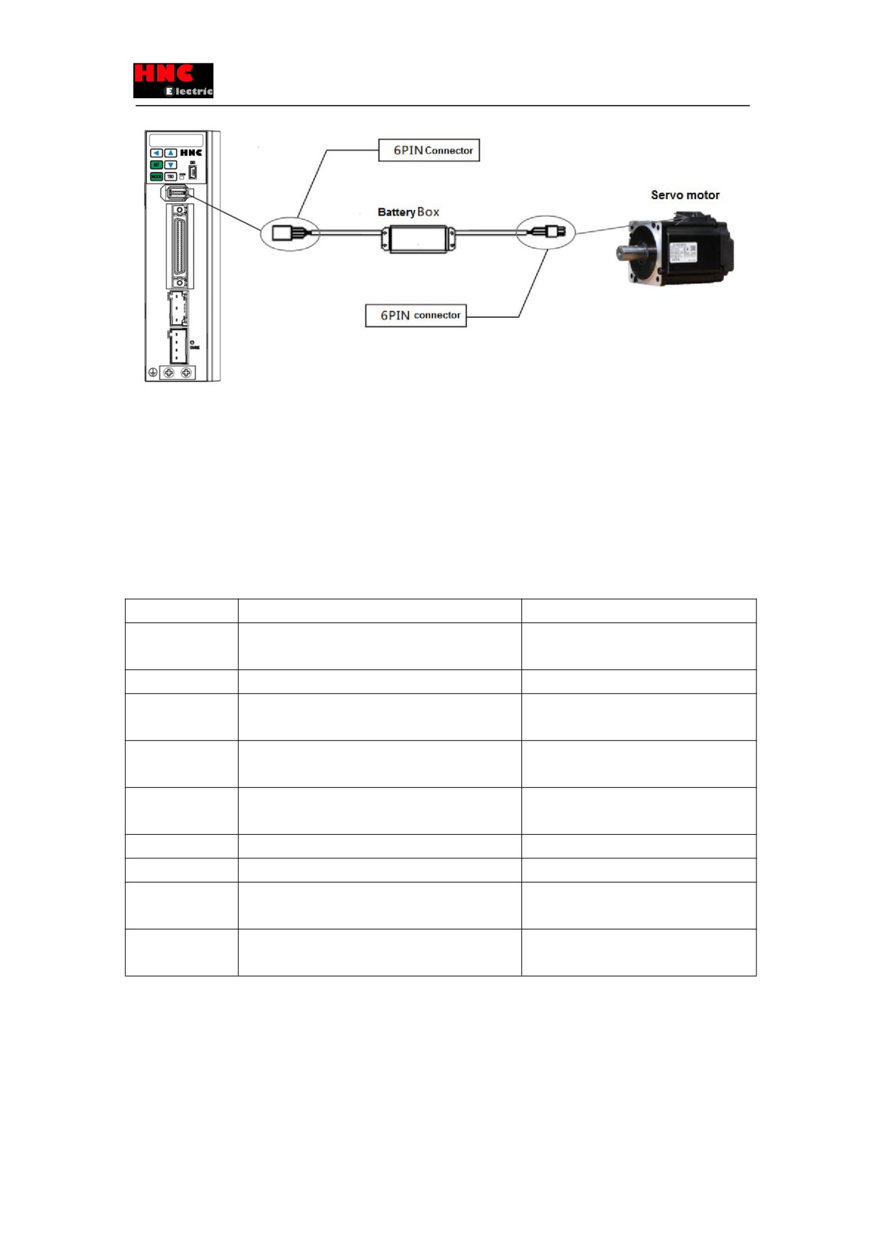
Figure 1 Installation of battery box cable
Install the battery box on the cable between the drive and motor encoder.
①Cut off 200VAC and 24VDC, take off the encoder cable from the motor
②Connect the battery box after check the connection direction
③Operate as the「5 Absolute encoder initialization」
[4.2 Battery specification]
The battery for absolute system are recommended as below:
Table 3 Basic specifications(recommended battery)
Items
Description
Remark
Battery
CR-AGB/C23P
Made by Panasonic Note 1)
Series : CR-AG
Nominal voltage
3. 0V
Nominal capacity
2400mAh
Capacity at the temperature of 20℃,
standard discharge current, voltage 1.8V
Standard discharge
2. 5mA
current,
Max. continuous
1A
At the temperature of 20℃
discharge current
Appearance
As shown in the <Appearance>
Note 2)
Weight
24g
Temperature
Working temperature:-40℃ ~ +70℃
No condensation
Storage temperature:-20℃ ~ +45℃
Recommended
Temperature:5℃ ~ 35℃
storage condition
Humidity:70%RH or less
Note 1) Primary lithium battery. Do not charge to avoid the burst.
Note 2) No significant appearance damage and have the obvious identification.
<Appearance>
172
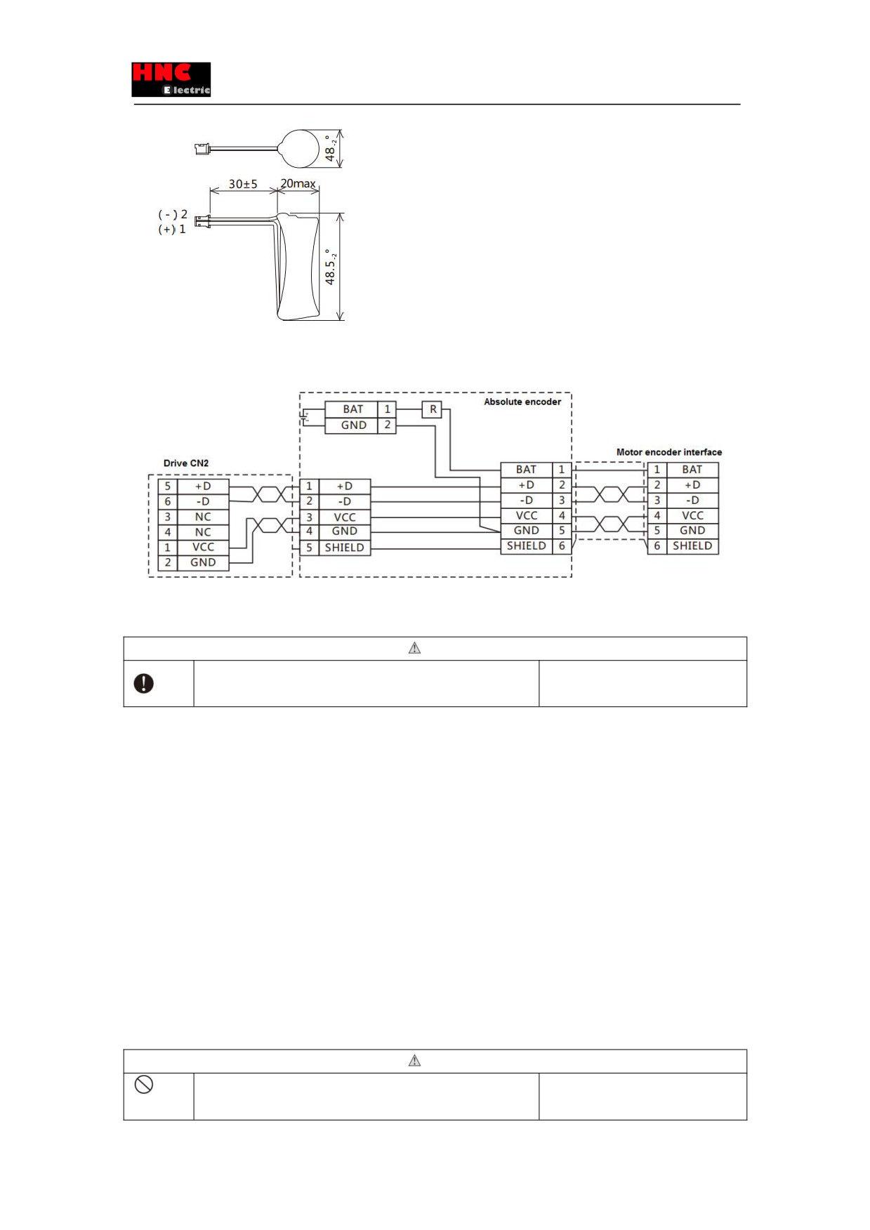
Figure 2 Recommended battery
[4.3 Battery box wiring]
Figure 3 Battery wiring
< When you make your own cable for absolute encoder >
Caution
Please use the battery recommended by our company.
To avoid the electric shock, injury,
Wire correctly.
malfunction or damage.
Please follow the wiring diagram as above. End user prepare the connectors and cables.
The batteries recommended by the company must be used. Using the battery, which does not meet the specifications, may
damage the battery in the worst situation.
For the operating and storage location
・Indoors, free from rain and direct sunlight
・Free from the corrosive gas, oil mist, iron powder
・Good ventilation, no moisture
・No excessive pollution and dust
・No vibration
・No impact to the battery
[4.4 Battery change]
When the battery voltage is too low, the alarm occurs.
At this time, it is necessary to change the battery, which should be done under the condition that the 24V control power for the
servo drive is ON. If not, the multi-rotation data will be lost and need to operate the mechanical home position return once
again.
Caution
・Check the polarity of the battery
To avoid the electric shock, injury,
・Do not disassemble the battery
malfunction or damage.
173
・Do not short-circuit the battery
・Do not charge the recommended battery
5 Absolute encoder initialization
Absolute encoder initialization is the encoder clearing. This can be done by the set panel . After encoder clearing, switch off
the 24VDC power. The multi-rotation data has been cleared after switch on the control power again.
[5.1 Method for encoder clearing by set panel]
1) Change the drive parameters(set absolute system and RS-485 communication)
1. Turn on 24VDC power when not connected with the encoder. Change the parameters if no alarm occurs.
2. Change the Parameter No.4.0 Communication address from “initial value 1” to the expected communication address
No. . The setting range is from 1 to 32. Change Parameter No.8.0 Selection of host communication method from “initial value
0” to “1(RS-485 asynchronous serial communication)”. Change the parameterNo.257.0 from “initial value 0 (Incremental
system) to “1(Absolute system)”. For the parameter change method, refer to SV-E3 User Manual「5-6
Parameter setting
mode」
3. Refer to SV-E3 User Manual「5-8
Parameter saving mode」to save the parameters. If not save the parameters, the
changed parameters will be invalid when power ON next time.
4. Switch off the control power (24V).
2) Restart the power
1. Refer to「4-1 Battery box cable installation 」to connect the battery box to the encoder and turn on the control power.
2. When restart the control power, the encoder error (
) will display on the set panel. Simultaneously, the
multi-rotation data error ( Er r . 20) and encoder low-voltage error occur (Err. 21).
3) Move to the home position
Move the axis which does not set the home position to the home position. When moving to the home position by manual is
possible, move it to the home position. This should be done at servo ON. Move them around the home position and perform
the operation of 4) to 6), then 4) to 5).
4) Operating the encoder clearing by set panel
1. Make the panel display
. When display
, press the MODE(
) button for seven times.
2. Refer to the following figure to press the SET (
) button once and UP(
) button once to display
3. Press the SET(
) button to display
4. After long-press the LEFT(
) button to show
,
displays and the multi-rotation data
become 0.
5.Switch off the control power. Until now, the absolute encoder initialization has been completed.
The operation procedures to have the encoder clearing by set panel are shown blow.
Operate the encoder clearing at servo OFF. If servo ON, the alarm
will occur.
174
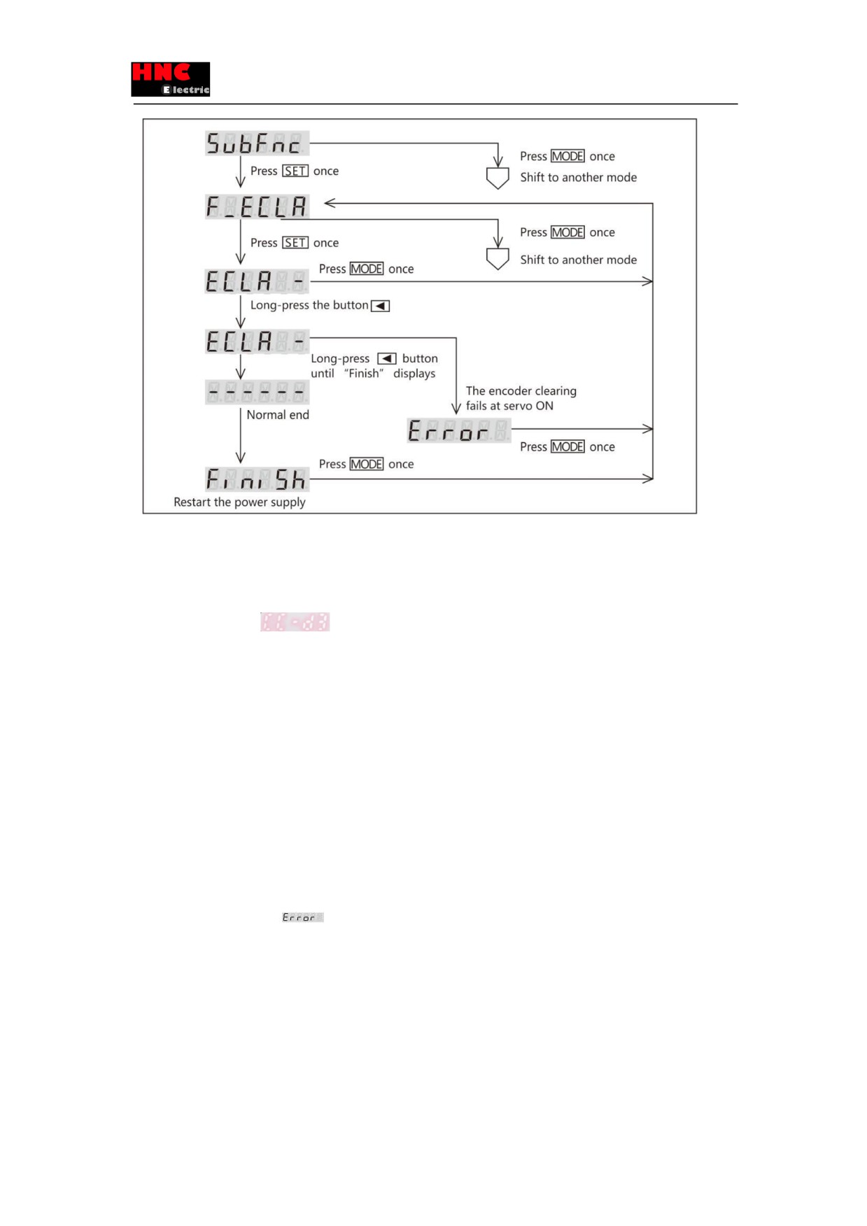
Figure 4 Operation procedures by set panel
5) Check if the encoder clearing succeeds
1. Turn on the control power
2. No alarm occurs and
display. No need for home position return even though switch off the power, unless
remove the battery.
3. Check the following items if alarm occurs.
★Install the battery or not.
★The battery voltage is normal or not.
★Cable connection is correct or not.
★Wiring is correct or not
After check the items above, do the 3) operation.
4. When determine the home position by manual, the absolute encoder setting completes. When the servo drive determines
the home position, after performing 6) operation procedures, then 4) and 5). The setting completes.
6) The servo drive moves to the home position(cannot move to the home position by manual)
1. The drive moves to the home position at servo ON. Please note that the current absolute data will change as the encoder
clearing will be done later.
2. Servo OFF. The alarm of
will occur at servo ON.
3. The absolute encoder setting completes after operation procedures of 4) and 5).
6) The servo drive moves to the home position(cannot move to the home position by manual)
1. The drive moves to the home position at servo ON. Please note that the current absolute data will change as the encoder
clearing will be done later.
2. Servo OFF. Cannot select [Encoder clearing] at servo ON.
3. The absolute encoder setting completes after operation procedures of 4) and 5).
175
6. Method of obtaining absolute data
The upper controller device can get the absolute data from the drive by RS-485 communication.
[6.1 Wiring for RS-485 communication]
Refer to 「4. 4 RS-485 communication 」for RS-485 communication wiring.
[6.2 About the communication between the upper controller and servo drive]
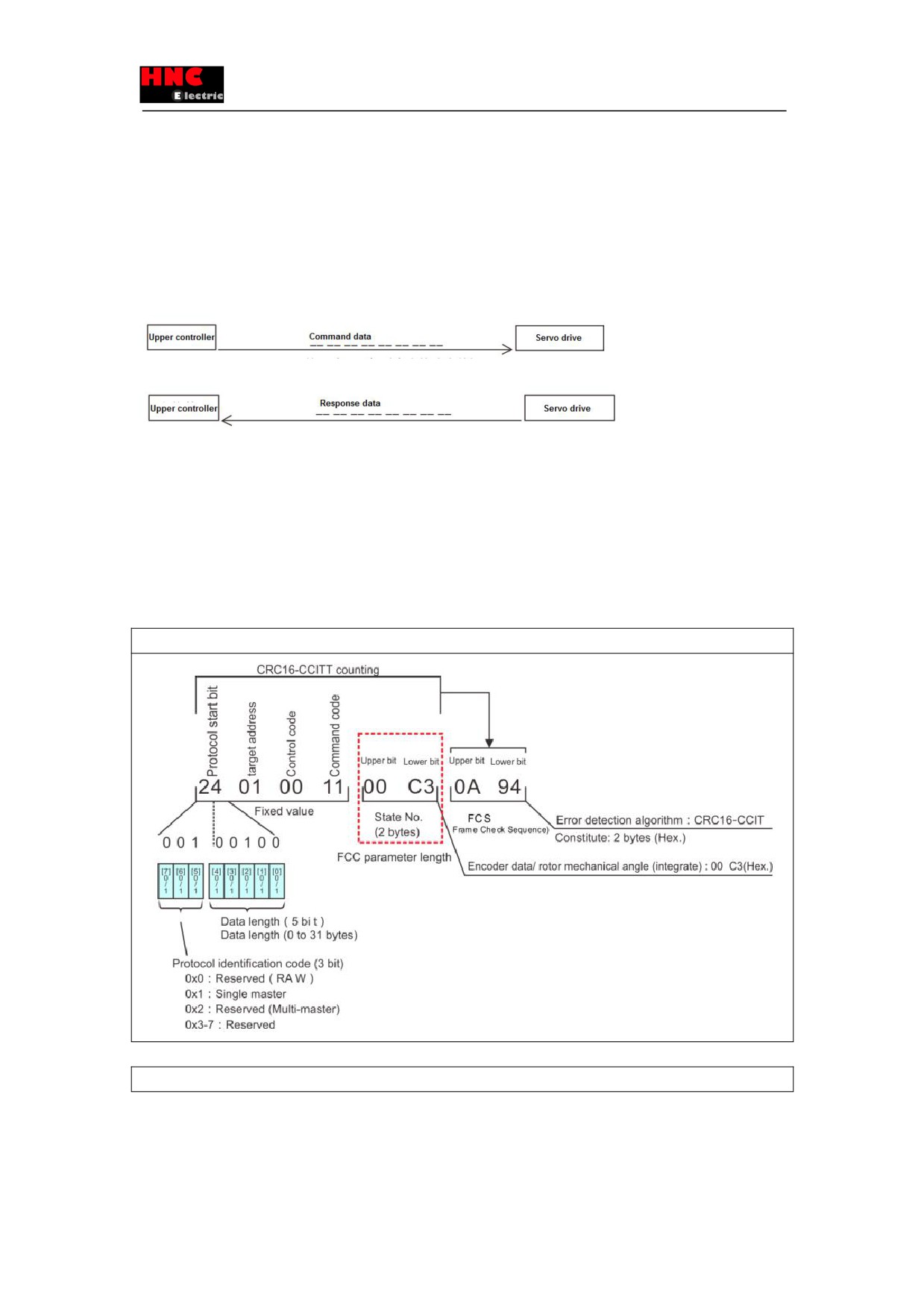
The upper controller device send communication command GET_STATE_VALUE_4 to read the encoder data by RS-485
communication. This communication command read the state value in 4 bytes.
STEP1) GET_STATE_VALUE_4 Send command
STEP2) G ET_STATE_VALUE_4 Answer the response data to the command from the drive
[6.3 Communication command description]
The absolute data are recorded by “Encoder/ rotor mechanical angle (integrate)”. The upper controller device get the
“Encoder/ rotor mechanical angle (integrate)”, that is the absolute data, from the communication data GET_STATE_VALUE_4.
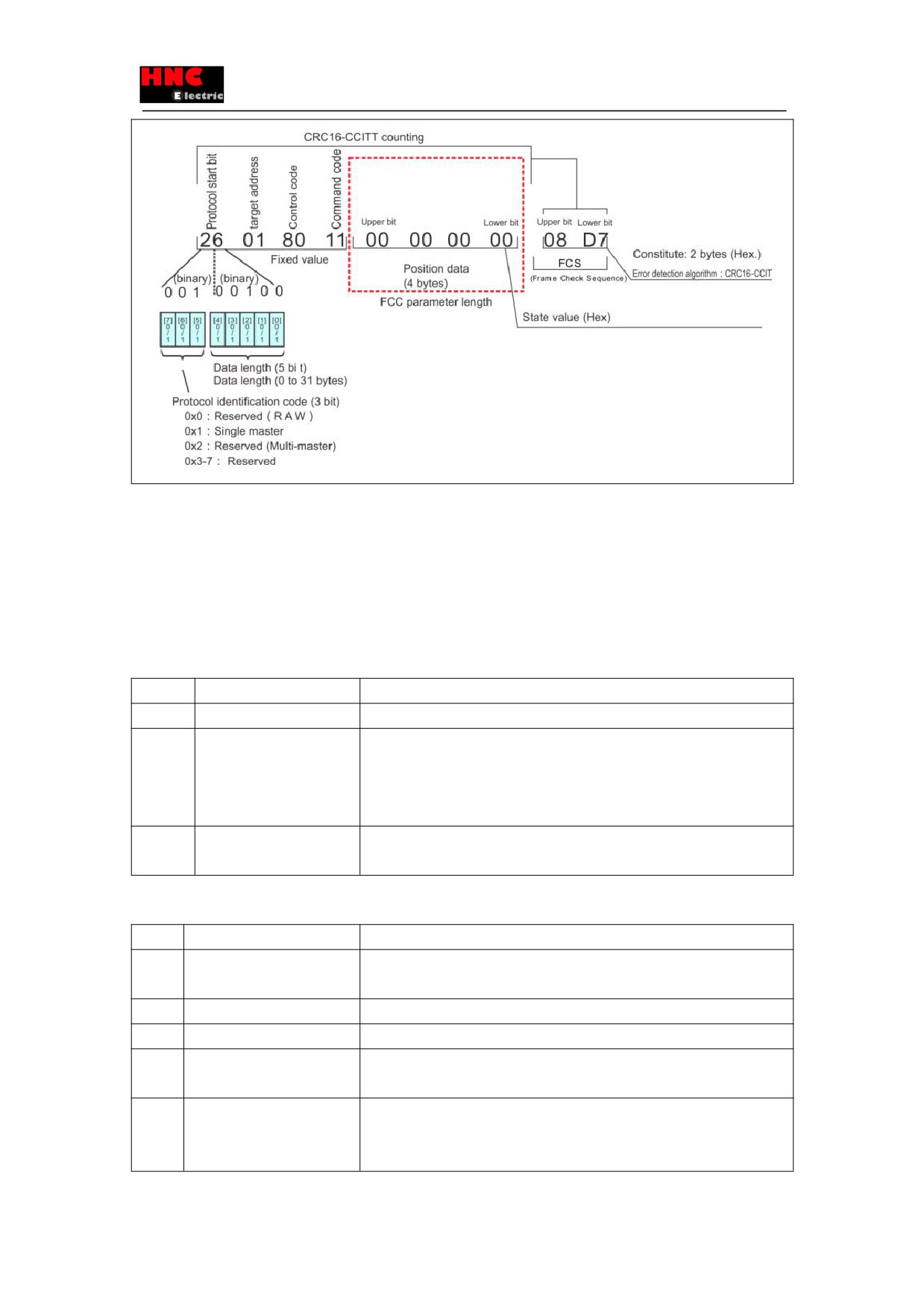
The sending and receiving method are shown in the following data example. Take the communication address (target address)
“01” as the example.
1. Execute the communication command GET_STATE_VALUE_4. The command code for GET_STATE_VALUE_4 is “11”.
2. The “Encoder/ rotor mechanical angle (integrate)” is used as the transmission data to input. The state variable code for
“Encoder/ rotor mechanical angle (integrate)” is “00C3”.
Sending data Example: Encoder / rotor mechanical angle (integrate)
3. Receives data with the specified state number.
Example of data reception
176
7. About alarms
The alarms in absolute system are shown below.
Relative to the incremental system alarm items, the absolute system adds the items of encoder error(( Err. 18)), multi-rotation
data error ((Er r. 2 0) and encoder low-voltage error(Err. 21). These alarms cannot be cleared by alarm resetting or restarting
the 24VDC control power. Restart the control power supply after encoder clearing.
Check the alarms on the [State display] screen
Table 9 Check the alarms on the [State display] screen
No.
Alarm items
Description・handling ways
18
Encoder error
The encoder itself error occurs.
20
Multi-rotation data error
☆The multi-rotation data changes sharply.
☆Check the encoder cable wiring and PIN contact
☆Perform FG grounding and countermeasures such as separation of power
cable and encoder cable.
21
Encoder low-voltage error
☆The multi-rotation data changes sharply.
☆Check if the battery voltage is too low for the absolute or battery cable loosen
For alarm details of the encoder, refer to the [Encoder] on the [Auxiliary function] screen.
Table 10 Alarm details for the encoder
No.
Alarm items
Description・handling ways
0
Speed error
The multi-rotation ABS sensor conversion error occurs at backup or speed error
occurs at power ON
1
MR
Low battery voltage warning
2
Multi-rotation ABS
Sensor communication error, cannot get the multi-rotation data at power ON.
3
Position error
The sensor error results in the different value between the 1-rotation ABS sensor
and multi-rotation ABS sensor, which unable to confirm the encoder position.
4
Low -voltage error
Only for multi-rotation ABS encoder
The supply voltage is under the voltage specification described in the manual at
power OFF.
177
5
EEPROM error
Cannot confirm the data stored in the EEPROM
6
Overheat alarm
The encoder base circuit temperature is beyond the setting temperature
7
Battery low-voltage error
The battery voltage is below the specified value (Note 1)
Note 1) Confirm the battery voltage at power ON and then check it every one hour.
178