HV610C Series Frequency Inverter. User Manual (Version: 3.1.14) - page 5
Section V. Parameter Function Table
Communication
5
AI1+AI2
6
MAX(|AI1|,|AI2|)
7
MIN(|AI1|,|AI2|)
8
It is used to select the feedback channel of PID
Feedback value of process PID is a relative value, set range is 0.0%~100.0%.
Positive action
0
FA.03
PID action direction
0
☆
Negative action
1
Positive action: If the feedback signal is smaller than the PID reference signal, it is required to boost
the output frequency of the inverter to make PID reach balance. The winding tension PID control is such a
case.
Negative action : If the feedback signal is smaller than the PID reference signal, it is required to
decrease the output frequency of the inverter to make PID reach balance.The unwinding tension PID
control is such a case.
This function is influenced by function 35,please pay attention during operation.
FA.04
PID reference feedback range
0~65535
1000
☆
PID reference feedback range is a dimensionless unit which is used to display U0.15 PID setup and
U0.16 PID feedback.
PID reference feedback related to the value 100.0%, corresponding to a given feedback range FA.04.If
FA.40 is set to 2000,PID is set to 100.0%,PID given display U0.15 is 2000.
FA.05
Proportional gain KF1
0.0~100.0
20.0
☆
FA.06
Integration time Ti1
0.01s~10.00s
2.00s
☆
FA.07
Differential time Td1
0.00~10.000
0.000s
☆
Proportional gain KF1 : the parameter determines the adjustable strength of PID regulator. The larger
P is, the greater the adjustable strength will be.When the parameter is set to 100.0, it means that when the
deviation between PID feedback value and reference value is 100.0%, the range for the PID regulator to
regulate the output frequency commands is the maximum frequency (integration effect and differential
effect are omitted).
Integration time Ti1 :determines the strength of PID integration regulation. The shorter the integration
time , the greater adjustable strength will be.Integration time means that when the deviation between PID
feedback value and reference value is 100%, the adjustment by the integration regulator (proportional
effect and differential effect are omitted) after continuous adjustment in this period reaches the maximum
frequency.
Differential time Td1 : determines the degree of adjustment that PID regulator performs on the
derivation between PID feedback value and reference value.Differential time means that if the feedback
value changes100% within this time, the adjustment by the differential regulator (proportional effect and
differential effect are omitted) will reach the maximum frequency.The longer differential time is, the higher
the degree of adjustment will be.
PID cutoff frequency of
FA.08
0.00~maximum frequency
2.00Hz
☆
reverse rotation
In some cases, only when the frequency of the PID output is negative (i.e., frequency inversion ) could
PID put the reference and feedback to the same state. High inversion frequency is not allowed in some
certain cases, FA.08 is used to determine reverse frequency upper limit.
90
Section V. Parameter Function Table
FA.09
PID deviation limit
0.0%~100.0%
0.0%
☆
It is used to set the maximum allowable deviation between the system feedback value and reference
value. When the deviation between the PID feedback and reference is within this range, the PID stops
adjustment. The deviation limit is calculated according to the percentage of the PID setup source (or
feedback source).When deviation between reference value and the feedback value is small,output
frequency is stability constant.It’s especially effective for some closed loop control occasions.
PID differential amplitude
FA.10
0.00%~100.00%
0.10%
☆
limit
In PID regulation, the role of differential is relatively sensitive that system oscillation may be easily
caused. Therefore, range of PID differential regulation has been limited to a small range. FA.10 is used to
set PID differential output range.
FA.11
PID reference change duration
0.00s~650.00s
0.00s
☆
PID reference changes according to this parameter value, which corresponds to the time taken for the
PID reference to change from 0% to 100%.
When PID reference changed,PID given value linear changes in accordance with given time,which can
reduce system adverse effect caused by given mutation.
FA.12
PID feedback filter time
0.00s~60.00s
0.00s
☆
FA.13
PID output filter time
0.00s~60.00s
0.00s
☆
FA.12 is used for filtering of PID feedback. The filtering helps to reduce the influence of the feedback
interference, but brings response performance of process closed-loop system.
FA.13 is used for filtering of PID output frequency. The filtering helps to reduce the mutations of the
output frequency, but brings response performance of process closed-loop system.
FA.14
Reserved
-
-
-
FA.15
Proportional gain KF2
0.0~100.0
20.0
☆
FA.16
Integration time Ti2
0.01s~10.00s
2.00s
☆
FA.17
Differential time Td2
0.00~10.000
0.000s
☆
No switching
0
PID parameter switching
FA.18
Switching through DI terminal
1
0
☆
condition
Switching through deviation
2
PID parameter switching
0.0%~FA.20
FA.19
20.0%
☆
deviation1
PID parameter switching
FA.20
FA.19~100.0%
80.0%
☆
deviation2
91
Section V. Parameter Function Table
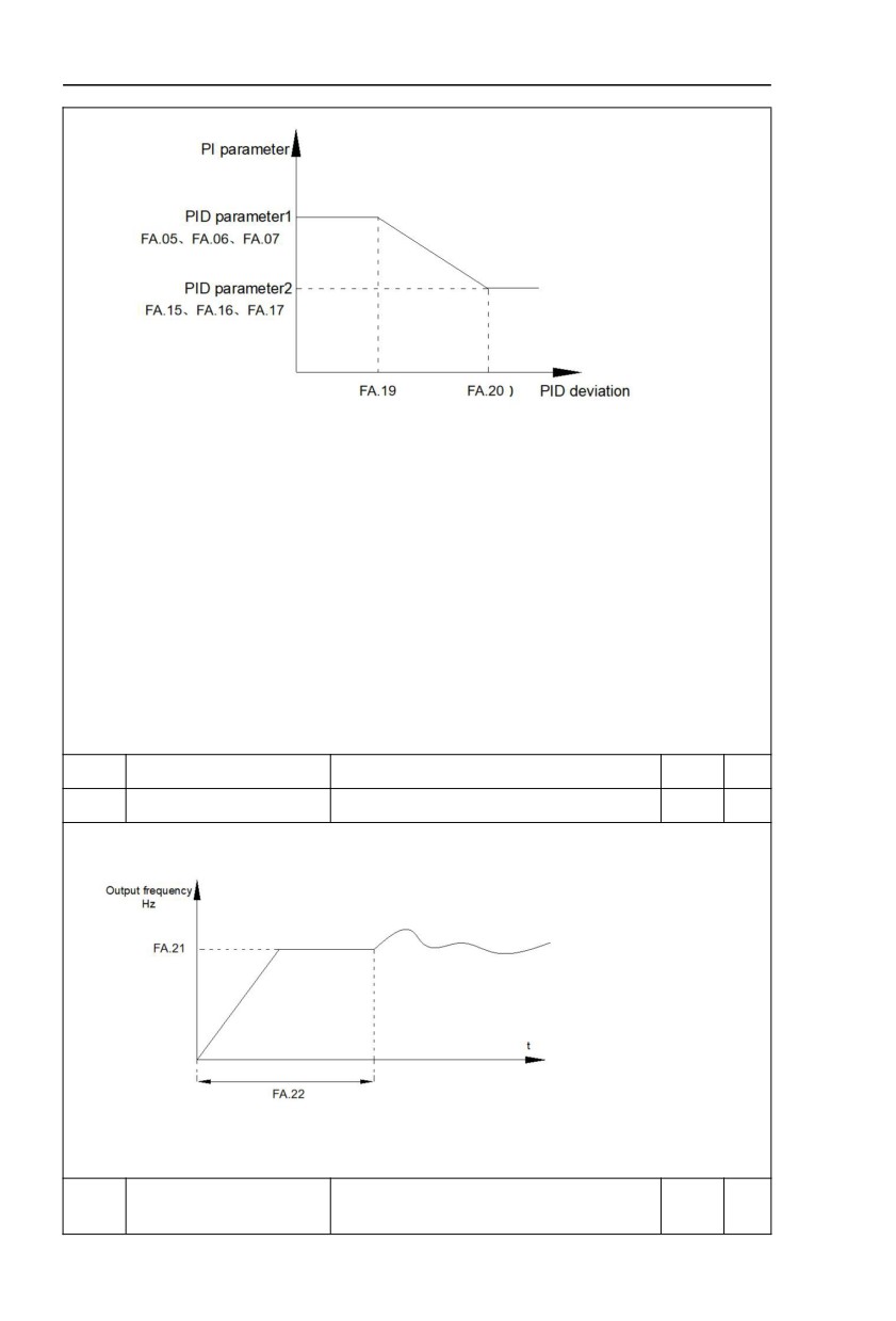
Fig.5-26 PID parameter switching schematic diagram
In some applications, one group of PID parameters can not meet the needs of the whole operation
process. Different parameters are used for different situations.
This group of function codes is used to switch 2 groups of PID parameters. Regulator parameters
FA.15~FA.17 and parameter FA.05~FA.07 have the same setting method.
Two groups of PID parameters can be switched through multi-function digital DI terminal as well as
PID deviation auto switching.
FA.18=1 : Set multi-function terminal to 43(PID parameter switching terminal). Choose parameter
group 1(FA.05~FA.07) when terminal invalid,while valid please choose parameter group 2 (FA.15~FA.17).
FA.18=2 : When deviation absolute value between reference and feedback is less than FA.19 set
value, PID parameters select parameter group 1. When deviation absolute value between reference and
feedback is greater than FA.20 set value, PID parameters select group 2. When deviation absolute value
between reference and feedback is within the range of switching deviation 1 &2 , PID parameters select
linear interpolation value of the 2 PID parameter groups.As shown in 5-26.
FA.21
PID initial value
0.0%~100.0%
0.0%
☆
FA.22
PID initial value retention time
0.00s~650.00s
0.00s
☆
Inverter fixed startup value is PID initial value(FA.21) .PID starts closed-loop regulation after PID initial
value retention time(FA.22).
Fig.5-27 PID initial function schematic diagram
This function is used to limit difference between the PID output two beat (2ms/ beat ), which
suppressing rapid change of PID output, so that the inverter operation tends to be stable.
Output deviation forward
FA.23
0.00%~100.00%
1.00%
☆
maximum value
92
Section V. Parameter Function Table
Output deviation reverse
FA.24
0.00%~100.00%
1.00%
☆
maximum value
FA.23 and FA.24 correspond to the output deviation maximum absolute value of forward running and
reverse running respectively.
1bit
Integration separation
Invalid
0
Valid
1
FA.25
PID integration attribute
00
☆
Whether stop integration when reaching
10bit
output limit
Continue integration
0
Stop integration
1
1bit :Integration separation
If integration separation valid, then when the multi-function digital DI integration suspended (function
22) effective, the PID integration stop operation, and only proportion and differential function effectively.
If integration separation invalid, regardless of validity of multi-function digital DI ,integration separation
is invalid.
10bit :Whether stop integration when reaching output limit
When PID operation output reaches the maximum or minimum value, user could choose whether to
stop integration or not.
If you choose to stop integration, then the PID integration stops calculation, which may contribute to
the reduction of PID overshoot.
No judging
0.0%
PID feedback loss detection
FA.26
0.0%
☆
value
0.1%~100.0%
0.1%
PID feedback loss detection
FA.27
0.0s~20.0s
0s
☆
time
This function is used to judge if PID feedback has been lost.
When PID feedback value is less than FA.26 set value, and lasted for more than FA.27 set value,
inverter fault alarm. Fault No. 31= Err31.
Stop without operation
0
FA.28
PID stop operation
0
☆
Stop with operation
1
It is used to select if PID keeping operation under PID stop status. Generally FA.28=0 in stop status.
5.13 Swing frequency, fixed length and counting:Fb.00-Fb.09
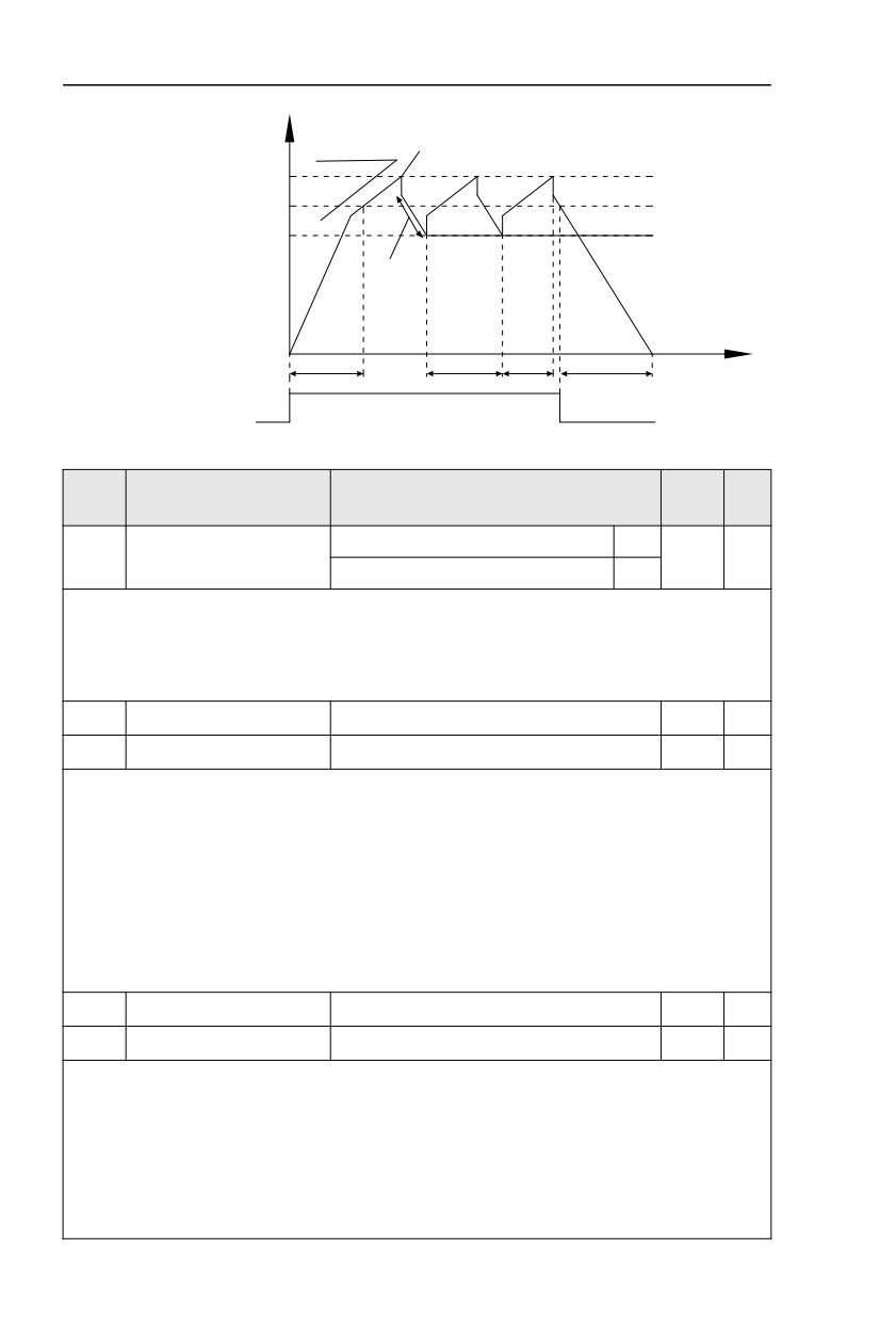
The swing frequency function is applicable to textile and chemical fiber industries and
applications where traversing and winding functions are required.
Swing frequency means that the inverter output frequency swings up and down with the
setup frequency as the center, and the trace of running frequency at the time axis is as shown in
Fig. 5-28.The swing amplitude is set by Fb.00 and Fb.01.
When Fb.01 is set to 0, it means the swing amplitude is 0, and the swing frequency is invalid.
93
Section V. Parameter Function Table
Output frequency
Swing frequency amplitude
Hz
Pb.00=0:Aw=Fset*Pb.01
Pb.00=1:Aw=Fmax*Pb.01
+Aw
Swing frequency upper limit
Central frequency Fset
-Aw
Swing frequency lower limit
Textile hopping frequency
=Aw*Pb.02
t
Acceleration according to acceleration time
Swing frequency cycle
Deceleration according to deceleration time
Triangle wave rise time
Running command
Fig.5-28Swing frequency schematic diagram
Description/
FactoryChange
Code
Setting Range
Keyboard Display
Setting
Limit
Relative to the center frequency
0
Fb.00
Swing setup mode
0
☆
Relative to the maximum frequency
1
It is used to determine the swing amplitude benchmark value.
0: Relative to the center frequency (F0.04 frequency source): It is a variable swing amplitude
system, with the swing amplitude changing with the center frequency (setup frequency).
1: Relative to the maximum frequency (F0.10 maximum output frequency): It is a fixed swing
amplitude system, with fixed swing amplitude that is calculated by the maximum frequency.
Fb.01
Swing frequency amplitude
0.0%~100.0%
0.0%
☆
Fb.02
Jump frequency amplitude
0.0%~50.0%
0.0%
☆
It is used to determine the amplitude value and the jump frequency value. Swing relative to the center
frequency (variable swing, select Fb.00=0) : Swing (AW) =frequency source F0.04 setup times swing
amplitude Fb.01. Swing relative to the maximum frequency (fixed swing, Fb.00=1) : Swing (AW) =
maximum frequency F0.10 times swing amplitude Fb.01. When the swing is running, the jump frequency
relative to the swing= Swing (AW) times jump frequency amplitude Fb.02.
If
“Swing relative to the center frequency (variable swing amplitude, Fb.00=0)” is selected, the jump
frequency is variable value.
If “Swing relative to the maximum frequency (fixed swing, Fb.00=1)” is selected, the jump frequency is
fixed value.
The swing operation frequency is constrained by upper frequency limit and lower frequency limit.
Fb.03
Swing frequency cycle
0.0s~3000.0s
10.0s
☆
Fb.04
Triangle wave rise time coef.
0.0%~100.0%
50.0%
☆
Swing frequency cycle : It defines the time of a whole cycle for rising and falling of the swing
frequency.
The coefficient of triangle wave rising time is Fb.04,it is time percentage of triangle rising time relating
to swing frequency cycle Fb.03.
Triangle wave rising time= Swing frequency cycle Fb.03 times triangle wave rising time coefficient
Fb.04(unit: s)
Triangle wave falling time= Swing frequency cycle Fb.03 times (1-triangle wave rising time coefficient
Fb.04) (unit: s)
94
Section V. Parameter Function Table
Fb.05
Setup length
0m~65535m
1000m
☆
Fb.06
Actual length
0m~65535m
0m
☆
Fb.07
Pulse number per meter
0.1~6553.5
100.0
☆
The three parameters such as setup length, actual length and number of pulses per meter are mainly
used for fixed-length control.
Length information needs to be collected through multi-function digit input terminal,you can get Fb.06
actual length by division of terminal sampling pulse number and Fb.06.When actual length is longer than
reference length Fb.05,multi-function digit terminal DO output “length arrival” ON signal.
During the process of fixed-length control,length reset operation(by multi-function terminal DI)is
permitted(choose DI function selection as 28),for specifications please refer to F4.00~F4.09.
Set corresponded input terminal function to “length counting input”(function 27).When pulse frequency
is high,only X5 port can be used.
Fb.08
Counting value setup
1~65535
1000
☆
Fb.09
Designated counting value
1~65535
1000
☆
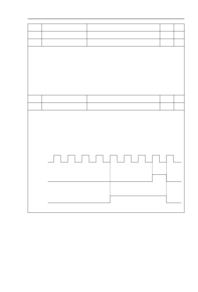
Counting value should be collected through multi-function digital input terminal. Corresponding input
terminal should be set to the function of “counter input”(function 25) in application. X5 terminal should be
used when pulse frequency is high.
When counting value reaches Fb.08 set value, multi-function digit DO output “setup counting value
arrival” ON signal, then stop counting.
When counting value reaches Fb.09 set value, multi-function digit DO output “designatedcounting
value arrival”ON signal, then continues to count until reaching “setup counting value”.
Specified counting value should not be greater than setup counting value Fb.08.
1
2
3
4
5
6
7
8
9
Pulse counting
DI5
Set counting
DO1
Designated counting
relay
Fig.5-29 Setup counting value&designated counting value schematic diagram
95
Section V. Parameter Function Table
5.14 MS speed function&simple PLC function:FC.00-FC.51
The multi-stage speed command of this inverter has more abundant functions than the
usual multi-stage speed. In addition to realizing the multi-stage speed function, it can also be
used as a voltage source for V and F separation and a given source of process PID. For this
reason, the dimension of the multi-segment command is relative value. Simple PLC can only
complete simple combined operation of multi-segment instructions.
Description/
FactoryChange
Code
Setting Range
Keyboard Display
Setting
Limit
FC.00
MS command 0
-100.0%~100.0%
0.0%
☆
FC.01
MS command 1
-100.0%~100.0%
0.0%
☆
FC.02
MS command 2
-100.0%~100.0%
0.0%
☆
FC.03
MS command 3
-100.0%~100.0%
0.0%
☆
FC.04
MS command 4
-100.0%~100.0%
0.0%
☆
FC.05
MS command 5
-100.0%~100.0%
0.0%
☆
FC.06
MS command 6
-100.0%~100.0%
0.0%
☆
FC.07
MS command 7
-100.0%~100.0%
0.0%
☆
FC.08
MS command 8
-100.0%~100.0%
0.0%
☆
☆
FC.09
MS command 9
-100.0%~100.0%
0.0%
FC.10
MS command 10
-100.0%~100.0%
0.0%
☆
FC.11
MS command11
-100.0%~100.0%
0.0%
☆
☆
FC.12
MS command 12
-100.0%~100.0%
0.0%
FC.13
MS command 13
-100.0%~100.0%
0.0%
☆
FC.14
MS command 14
-100.0%~100.0%
0.0%
☆
☆
FC.15
MS command 15
-100.0%~100.0%
0.0%
MS speed command can be used on three occasions : frequency source, VF saparation voltage
source, process PID set source.
Dimension of MS speed command is a relative value ranging from -100.0% to 100.0%. When used as
command source, it’s the percentage of maximum frequency. When used as VF separation voltage source,
it’s the percentage of motor rated voltage. When used as PID set source, dimension conversion is not
needed during the process.
MS command should be selected according to the different states of multi-function digit DI terminals.
For details please refer to F4 group.
Single running stop
0
FC.16
PLC running mode
Single running end remaining final value
1
0
☆
Continuous circulation
2
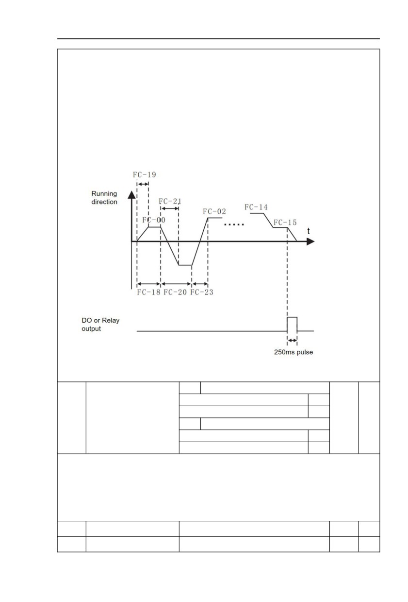
Simple PLC command can be used on two occasions:frequency source, VF saparation voltage source.
Fig 5-30 is the schematic diagram of simple PLC that used as frequency source. Positive & negative of
FC.00~FC.15 determines the running direction.
96
Section V. Parameter Function Table
PLC has 3 running modes as frequency source(VF saparation voltage source is not provided with the
3 modes):
0: Single running stop
Upon completion of one single cycle of the inverter, it will stop automatically and will not start until
running command is given again.
1:Single running end remaining final value
Upon completion of one single cycle of the inverter, the inverter will remain the running frequency and
direction of last one phase. After the inverter restarted upon stop, it will run from the initial status of PLC.
2: Continuous circulation
Upon completion of one single cycle of the inverter, it will enter next cycle and not stop until stop
command is given.
Fig.5-30Simple PLC schematic diagram
1bit
Power off memory selection
Power off without memory
0
PLC power off memory
Power off with memory
1
FC.17
00
☆
selection
10bit
Stop memory selection
Stop without memory
0
Stop with memory
1
PLC power off memory refers to memorizing the PLC running stage and running frequency before
power off, and continues to run from the memory stage upon next power-on. If 1bit is set to 0, PLC process
would restart upon power-on.
PLC stop memory refers to the record of PLC running stage and running frequency of the time before.
Next time PLC continues to run from the memory stage. If 10bit is set to 0, PLC process would restart upon
power-on.
☆
FC.18
PLC 0 segment running time
0.0s(h) ~ 6553.5s(h)
0.0s(h)
FC.19
PLC 0 segment acc./dec. time
0~3
0
☆
97
Section V. Parameter Function Table
FC.20
PLC 1segment running time
0.0s(h)~6553.5s(h)
0.0s(h)
☆
☆
FC.21
PLC 1segment acc./dec. time
0~3
0
☆
FC.22
PLC 2segment running time
0.0s(h)~6553.5s(h)
0.0s(h)
FC.23
PLC 2segment acc./dec. time
0~3
0
☆
FC.24
PLC 3segment running time
0.0s(h)~6553.5s(h)
0.0s(h)
☆
☆
FC.25
PLC 3segment acc./dec. time
0~3
0
FC.26
PLC 4segment running time
0.0s(h)~6553.5s(h)
0.0s(h)
☆
FC.27
PLC 4segment acc./dec. time
0~3
0
☆
☆
FC.28
PLC 5 segment running time
0.0s(h)~6553.5s(h)
0.0s(h)
FC.29
PLC 5segment acc./dec. time
0~3
0
☆
FC.30
PLC 6segment running time
0.0s(h)~6553.5s(h)
0.0s(h)
☆
☆
FC.31
PLC 6segment acc./dec. time
0~3
0
☆
FC.32
PLC 7segment running time
0.0s(h)~6553.5s(h)
0.0s(h)
FC.33
PLC 7segment acc./dec. time
0~3
0
☆
FC.34
PLC 8segment running time
0.0s(h)~6553.5s(h)
0.0s(h)
☆
☆
FC.35
PLC 8segment acc./dec. time
0~3
0
FC.36
PLC 9segment running time
0.0s(h)~6553.5s(h)
0.0s(h)
☆
FC.37
PLC 9segment acc./dec. time
0~3
0
☆
☆
FC.38
PLC 10segment running time
0.0s(h)~6553.5s(h)
0.0s(h)
FC.39
PLC 10segment acc./dec.time
0~3
0
☆
FC.40
PLC 11segment running time
0.0s(h)~6553.5s(h)
0.0s(h)
☆
☆
FC.41
PLC 11segment acc./dec. time
0~3
0
☆
FC.42
PLC 12segment running time
0.0s(h)~6553.5s(h)
0.0s(h)
FC.43
PLC 12segment acc./dec. time
0~3
0
☆
FC.44
PLC 13segment running time
0.0s(h)~6553.5s(h)
0.0s(h)
☆
☆
FC.45
PLC 13segment acc./dec. time
0~3
0
FC.46
PLC 14segment running time
0.0s(h)~6553.5s(h)
0.0s(h)
☆
FC.47
PLC 14segment acc./dec. time
0~3
0
☆
☆
FC.48
PLC 15segment running time
0.0s(h)~6553.5s(h)
0.0s(h)
FC.49
PLC 15segment acc./dec. time
0~3
0
☆
S(second)
0
FC.50
Running time unit
0
☆
H(hour)
1
Function code FC.00 reference
0
FC.51
MS command 0 reference
0
☆
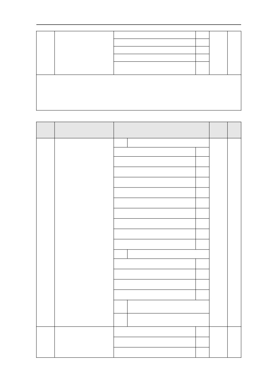
AI1
1
98
Section V. Parameter Function Table
mode
AI2
2
AI3
3
PULSE
4
PID
5
Preset frequency(F0.08) reference,
6
UP/DOWN can be modified
It is used to select the reference channel of MS speed 0.
Besides choosing FC.00, MS command 0 has many other options, which is convenient for switching
between MS command and other set modes.
Both MS command and simple PLC used as frequency source can easily realize switching between
the two frequency sources.
5.15 Communication function group:Fd.00-Fd.06
Description/
FactoryChange
Code
Setting Range
Keyboard Display
Setting
Limit
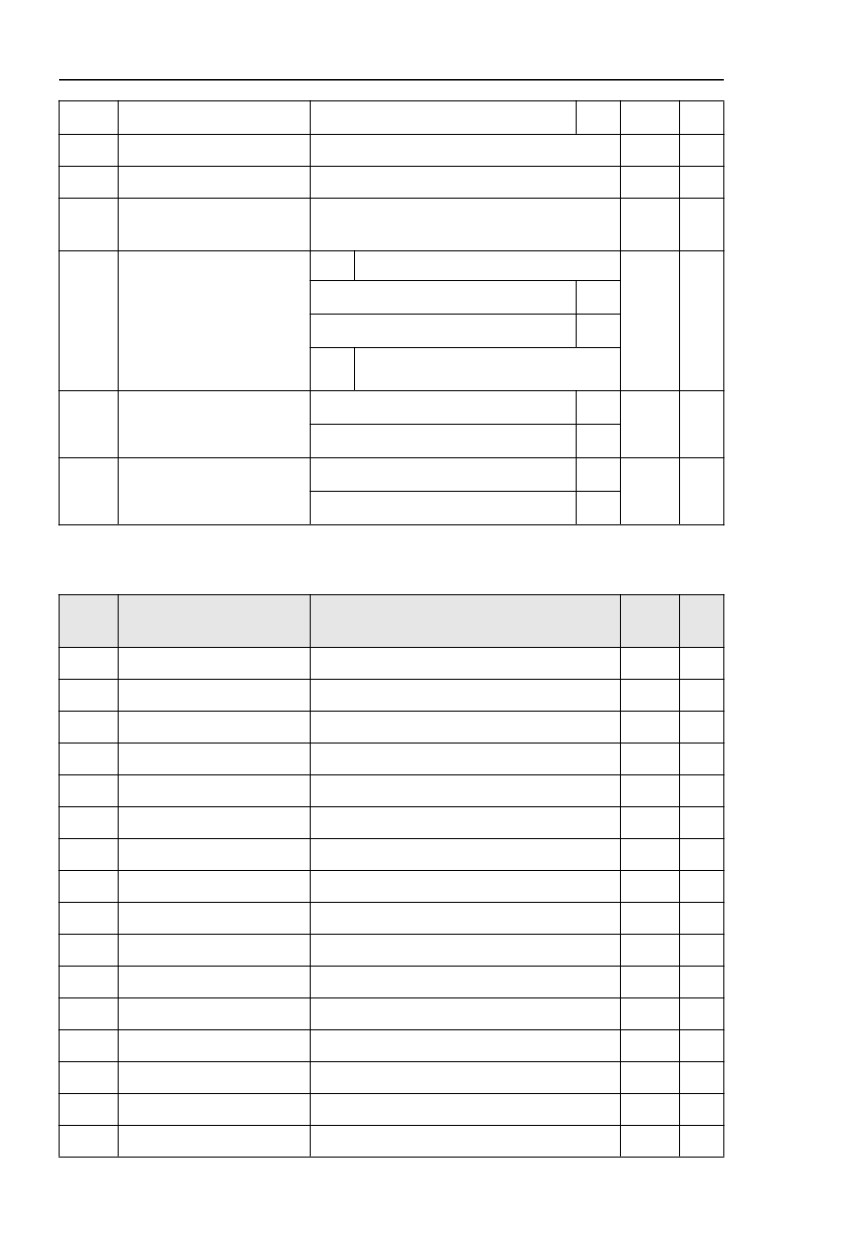
1bit
MODBUS
300BPS
0
600BPS
1
1200BPS
2
2400BPS
3
4800BPS
4
9600BPS
5
19200BPS
6
38400BPS
7
Fd.00
Baud rate
6005
☆
57600BPS
8
115200BPS
9
10bit
Profibus-DP
115200BPS
0
208300BPS
1
256000BPS
2
512000BPS
3
100
Reserved
bit
1000
Reserved
bit
None parity check (8-N-2)
0
Fd.01
Data format
Even parity check (8-E-1)
1
0
☆
Odd parity check(8-O-1)
2
99
Section V. Parameter Function Table
None parity check (8-N-1)
3
Fd.02
Local address
1-247, 0 is broadcast address
1
☆
Fd.03
Response delay
0ms-20ms
2
☆
Excessive communication
Fd.04
0.0(invalid), 0.1s-60.0s
0.0
☆
time
1bit
MODBUS
Non-standard MODBUS protocol
0
Fd.05
Data transformation selection
30
☆
Standard MODBUS protocol
1
10
Reserved
bit
0.01A
0
Communication read
Fd.06
0
☆
current resolution
0.1A
1
MODBUS protocol
0
Serial communication
Fd.08
0
☆
protocol selection
Reserved
1
5.16 User customization function code:FE.00-FE.29
Description/
FactoryChange
Code
Setting Range
Keyboard Display
Setting
Limit
FE.00
User function code 0
F0.00~FP.xx,A0.00~Ax.xx,U0.xx
F0.09
☆
FE.01
User function code 1
F0.00~FP.xx,A0.00~Ax.xx,U0.xx
F0.02
☆
FE.02
User function code 2
F0.00~FP.xx,A0.00~Ax.xx,U0.xx
F0.03
☆
FE.03
User function code 3
F0.00~FP.xx,A0.00~Ax.xx,U0.xx
F0.04
☆
FE.04
User function code 4
F0.00~FP.xx,A0.00~Ax.xx,U0.xx
F0.07
☆
FE.05
User function code 5
F0.00~FP.xx,A0.00~Ax.xx,U0.xx
F0.19
☆
FE.06
User function code 6
F0.00~FP.xx,A0.00~Ax.xx,U0.xx
F0.20
☆
FE.07
User function code 7
F0.00~FP.xx,A0.00~Ax.xx,U0.xx
F3.00
☆
FE.08
User function code 8
F0.00~FP.xx,A0.00~Ax.xx,U0.xx
F3.01
☆
FE.09
User function code 9
F0.00~FP.xx,A0.00~Ax.xx,U0.xx
F4.00
☆
FE.10
User function code 10
F0.00~FP.xx,A0.00~Ax.xx,U0.xx
F4.01
☆
FE.11
User function code 11
F0.00~FP.xx,A0.00~Ax.xx,U0.xx
F4.02
☆
FE.12
User function code 12
F0.00~FP.xx,A0.00~Ax.xx,U0.xx
F5.04
☆
FE.13
User function code 13
F0.00~FP.xx,A0.00~Ax.xx,U0.xx
F5.07
☆
FE.14
User function code 14
F0.00~FP.xx,A0.00~Ax.xx,U0.xx
F6.00
☆
FE.15
User function code 15
F0.00~FP.xx,A0.00~Ax.xx,U0.xx
F6.10
☆
100
Section V. Parameter Function Table
FE.16
User function code 16
F0.00~FP.xx,A0.00~Ax.xx,U0.xx
F0.18
☆
FE.17
User function code 17
F0.00~FP.xx,A0.00~Ax.xx,U0.xx
F0.00
☆
FE.18
User function code 18
F0.00~FP.xx,A0.00~Ax.xx,U0.xx
F0.00
☆
FE.19
User function code 19
F0.00~FP.xx,A0.00~Ax.xx,U0.xx
F0.00
☆
FE.20
User function code 20
F0.00~FP.xx,A0.00~Ax.xx,U0.xx
F0.00
☆
FE.21
User function code 21
F0.00~FP.xx,A0.00~Ax.xx,U0.xx
F0.00
☆
FE.22
User function code 22
F0.00~FP.xx,A0.00~Ax.xx,U0.xx
F0.00
☆
FE.23
User function code 23
F0.00~FP.xx,A0.00~Ax.xx,U0.xx
F0.00
☆
FE.24
User function code 24
F0.00~FP.xx,A0.00~Ax.xx,U0.xx
F0.00
☆
FE.25
User function code 25
F0.00~FP.xx,A0.00~Ax.xx,U0.xx
F0.00
☆
FE.26
User function code 26
F0.00~FP.xx,A0.00~Ax.xx,U0.xx
F0.00
☆
FE.27
User function code 27
F0.00~FP.xx,A0.00~Ax.xx,U0.xx
F0.00
☆
FE.28
User function code 28
F0.00~FP.xx,A0.00~Ax.xx,U0.xx
F0.00
☆
FE.29
User function code 29
F0.00~FP.xx,A0.00~Ax.xx,U0.xx
F0.00
☆
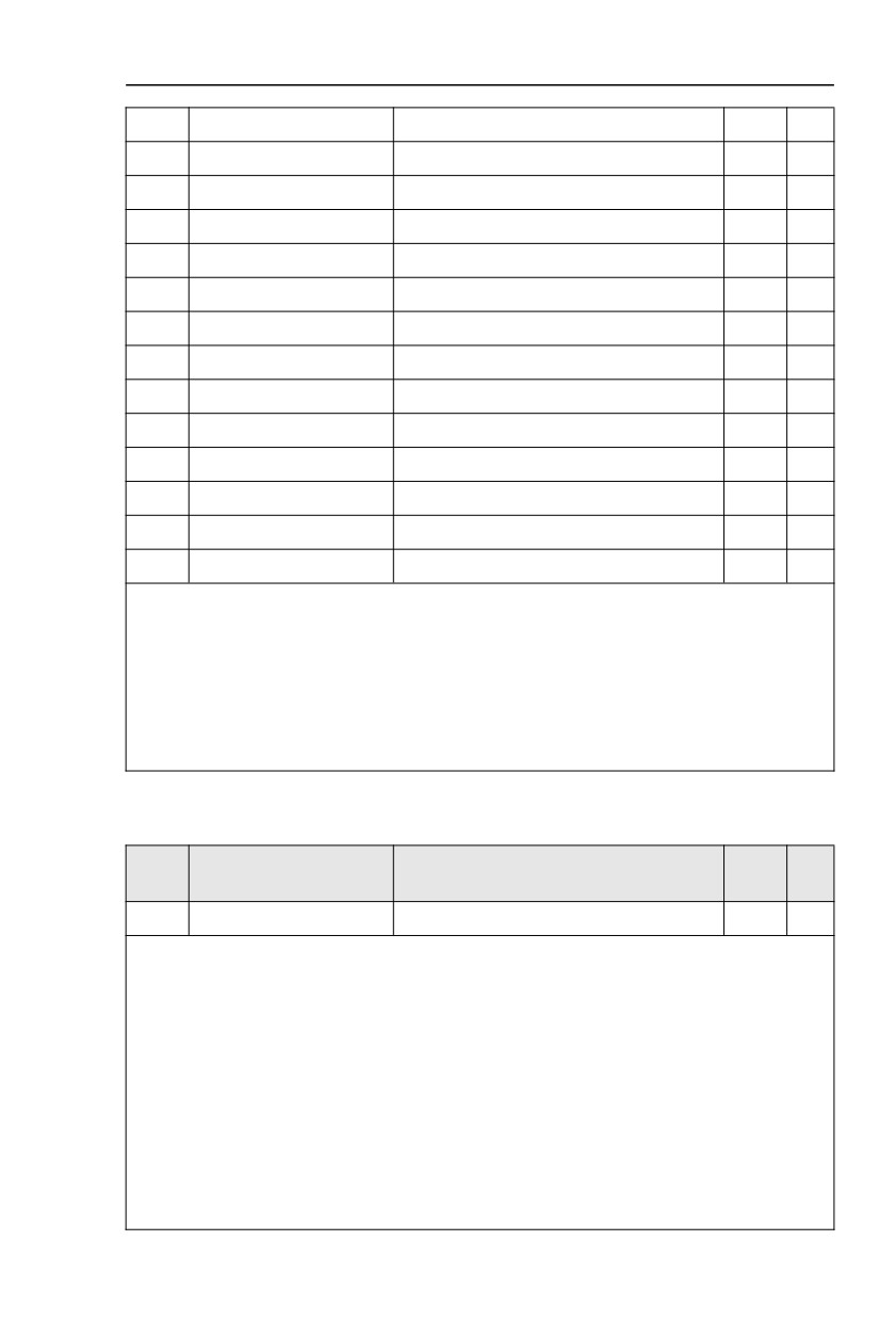
This function group is the user customization function code.
Users can put the required parameters (among all HV610C function codes) to the FE group as the
user customization function group.
FE group can offer 30 user customization function codes at most.When FE displays F0.00, it means
user function code is null.
In user customization function mode, display of the function codes is defined through FE.00~FE.31.
Sequence is consistent with the FE function codes, skip F0.00.
5.17 Function code management:FP.00-FP.04
Description/
FactoryChange
Code
Setting Range
Keyboard Display
Setting
Limit
FP.00
User password
0~10000
0
☆
The password set function is used to prohibit the unauthorized person from viewing and modifying
the parameters.
When the parameter is set to any non-zero number, the password protection function is enabled. If
no password is needed, change the parameter value to 00000.
After the user password is set and takes effect, when entering the password setting state, if the
user password is incorrect, you cannot view and modify the parameter. You can only view the operation
display parameters and stop displaying parameters.
Please keep your password in mind. If you set the password mistakenly orforget the password,
please contact the manufacturer.
101
Section V. Parameter Function Table
No function
0
Restore to factory default value,motor
FP.01
Parameter initialization
1
0
★
parameter not included
Clear memory
2
0: No function.
1:Restore to factory default value,motor parameter not included
Motor parameters, F0.22, fault record information, F7.09, F7.13, F7.14.will not be restored.
2:Clear memory
The inverter clears the fault records , F7.09, F7.13 and F7.14 to zero.
1bit
U group display selection
No display
0
Display
1
FP.02
Parameter display attribute
11
★
10bit
A group display selection
No display
0
Display
1
1bit
Custom parameter display selection
No display
0
Personalized parameter
Display
1
FP.03
00
☆
display selection
10bit
User change parameter display selection
No display
0
Display
1
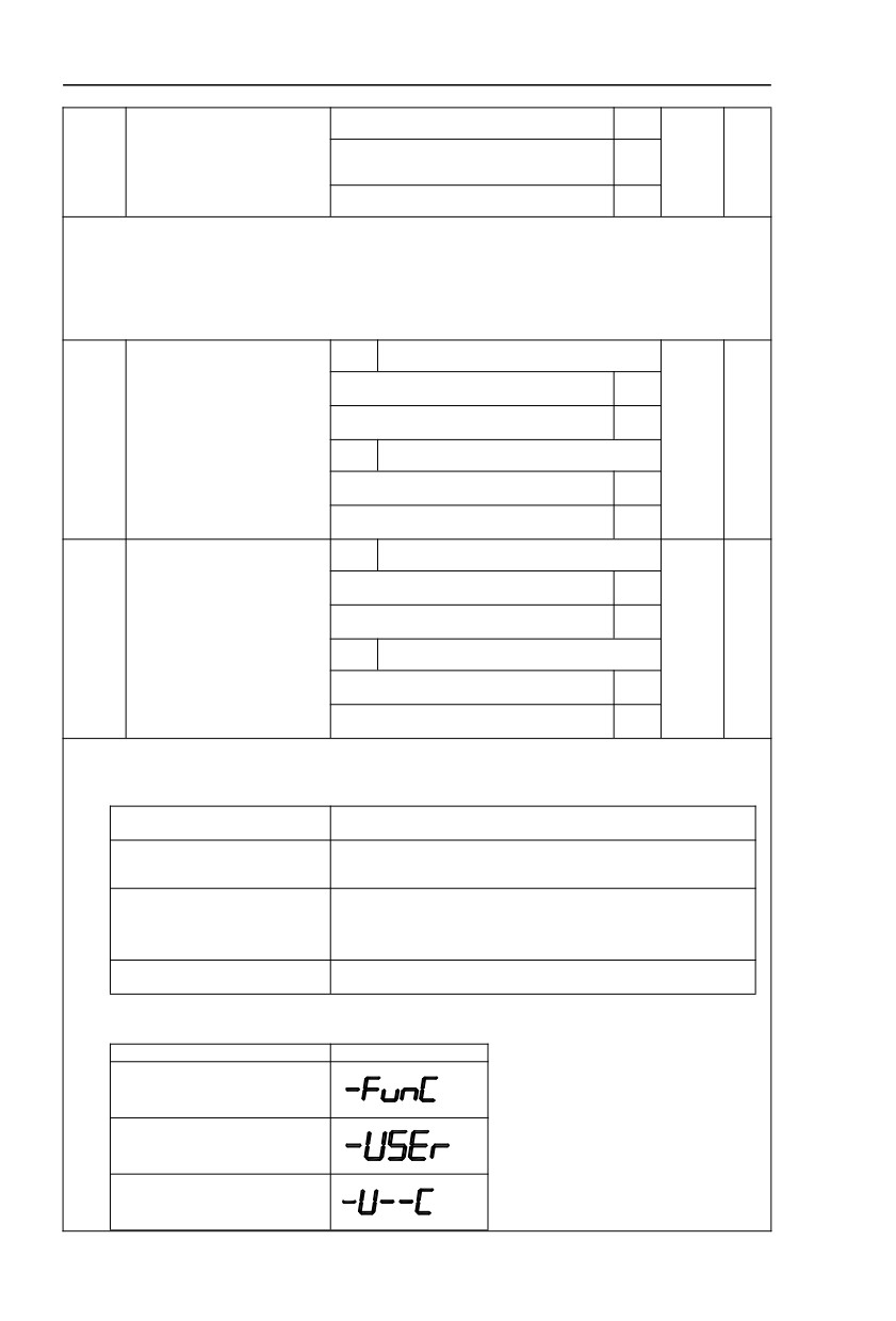
The establishment of parameter display selection is basically convenient for the users viewing the
different arrangement forms of function parameters according to the actual needs. Three display
methods are offered as below:
Name
Description
Sequence display inverter function parameters, respectively
Function parameter mode
F0~FF、A0~AF、U0~UF.
User customization display of specified function
User customization parameter
parameters(32
at most). The display parameters is
mode
determined through FE group.
User change parameter mode
Parameters which are different from factory default.
When existing display for FP.03, user could switch into different display mode through QUICK key.
Function parameter display mode as default.
Parameter display mode
Display
Function parameter mode-
FunC
User customization parameter
mode-USEt
User change parameter
mode-U--C
102
Section V. Parameter Function Table
Display codes as below:
HV610C series offers two groups of personalized parameter display mode : user customization
function mode, user change parameter mode.
In user customization parameter mode, sign u is added to the user customization function code as
default.
In user change parameter mode, sign c is added to the user customization function code as
default. E.g:F1.00 is displayed as cF1.00 .
Can be modified
0
Function codes modification
FP.04
0
☆
attribute
Can not be modified
1
This function is used to prevent misoperation of the function parameters.
FP.04=0:All the function codes can be modified.
FP.04=1:All the function codes can only be viewed, but not modified.
5.18 Torque control group: A0.00-A0.08
Description/
FactoryChange
Code
Setting Range
Keyboard Display
Setting
Limit
Speed control
0
Speed/ torque control mode
A0.00
0
★
selection
Torque control
1
A0.00 is used to select inverter control mode:speed control or torque control.
Multi-function digit DI terminal of HV610C is equipped with two functions relating torque control :
Torque control banned(Function29), speed control/torque control switching (function 46). The two terminals
should be matched with A0.00 to realize switching between speed control and torque control.
A0.00 set the control mode when speed/torque control switching terminal invalid. If the speed/torque
control switching terminal is valid, control mode is equivalent to the inversion of A0.00 value.
When function 29 is valid, speed control mode is fixed for the inverter .
Digital setup(A0.03)
0
AI1
1
AI2
2
AI3
3
Torque setup source selection
A0.01
0
★
in torque control mode
PULSE
4
Communication setup
5
MIN(AI1,AI2)
6
MAX(AI1,AI2)
7
Torque digital setup in torque
A0.03
-200.0%~200.0%
150%
☆
control mode
A0.01 is used to select torque set source. There are totally 8 kinds of torque set mode.
Torque set is a relative value, which 100% corresponding to inverter rated torque. Set range :
200.0%~200.0%.Maximum torque is 2 times that of inverter rated torque
When the torque is set by selection 1~7, 100% of communication ,analog input, pulse input
corresponding to A0.03.
Torque control forward
A0.05
0.00Hz~Maximum frequency(F0.10)
50.00Hz
☆
maximum frequency
103
Section V. Parameter Function Table
Torque control reverse
A0.06
0.00Hz~Maximum frequency(F0.10)
50.00Hz
☆
maximum frequency
A0.05, A0.06 are used to set forward or reverse maximum running frequency in torque control mode.
In inverter toque control mode, if load torque is less than motor output toque, the motor Speed
would speed up. In case of galloping or other accidents of mechanical system , motor maximum Speed
must be limited.
A0.07
Torque control acc. time
0.00s~65000s
0.00s
☆
A0.08
Torque control dec. time
0.00s~65000s
0.00s
☆
In torque control mode , rate of speed change of motor and load is decided by the difference
between motor output toque and load torque. Therefore, motor speed may change fast, causing noise
or excessive mechanical stress problems. By setting the torque control acc./dec. time, can make the
motor speed changes smoothly.
A0.07 and A0.08 should be set to 0.00s in situations where torque rapid response is needed.
E.g:Two motors drive the same load, to make sure of load uniform distribution , one is set as host
inverter(speed control mode) and another is the slave one(torque control mode). Actual output torque of
the host inverter is the torque command of the slave, and slave torque is required to quickly follow the
host torque, then torque control acc./dec. time is set to 0.00s for the slave inverter.
5.19 Virtual IO: A1.00-A1.21
Description/
FactoryChange
Code
Setting Range
Keyboard Display
Setting
Limit
A1.00
Virtual VX1 function selection
0~59
0
★
A1.01
Virtual VX2 function selection
0~59
0
★
A1.02
Virtual VX3 function selection
0~59
0
★
A1.03
Virtual VX4 function selection
0~59
0
★
A1.04
Virtual VX5 function selection
0~59
0
★
Functions of virtual VX1~VX5 are equal to DI terminals on control board. VX1~VX5 can be used as
multi-function digital input terminals, for details please refer to description of F4.00~F4.09 .
1bit
Virtual VX1
State of virtual VYx decides whether
0
VDI is effective
Function code A1.06 decide whether
1
VDI is effective
Virtual VD1
terminal valid
A1.05
10bit
Virtual VX2
00000
★
state set mode
State of virtual VYx decides whether
0
VDI is effective
Function code A1.06 decides whether
1
VDI is effective
100
Virtual VX3
bit
104
Section V. Parameter Function Table
State of virtual VDOx decides whether
0
VDI is effective
Function code A1.06 decides whether
1
VDI is effective
1000
Virtual VX4
bit
State of virtual VDOx decides whether
0
VDI is effective
Function code A1.06 decides whether
1
VDI is effective
10000
Virtual VX5
bit
State of virtual VDOx decides whether
0
VDI is effective
Function code A1.06 decides whether
1
VDI is effective
1bit
Virtual VX1
Invalid
0
Valid
1
10bit
Virtual VX2
Invalid
0
Valid
1
100bit
Virtual VX3
Invalid
0
A1.06
Virtual VD1 terminal state
00000
★
Valid
1
1000
Virtual VX4
bit
Invalid
0
Valid
1
10000
Virtual VX5
bit
Invalid
0
Valid
1
State of virtual VDI terminal can be set through 2 setting methods, which is different from common
digit input terminals, and select through A1.05.
When choosing the corresponding VDO state as the decision of VDI state , valid state of VDI is
depending on VDO output as valid or not. VDIx only binding VDOx( x :1~5).
Binary bits of function code A1.06 decide vitual input terminal states respectively.
105
Section V. Parameter Function Table
The following example illustrates the method of using virtual VDI.
E.g1 : When choosing VDO state deciding VDI state, to complete “AI1 input exceeding limit,
inverter fault alarm and stop”:
Set VX1 to “ user-defined fault 1”(A1.00=44);
Set VDO (A1.05=xxx0) to decide VX1 terminal valid state;
Set VDO output function to “AI1 excessive input”(A1.11=31);
When AI1 exceeding the upper / lower limit , VDO output ON signal, VX1 input terminal state is
valid, VX1 receives “ user-defined fault 1”, and inverter fault alarm and stop , fault No. 27= E.USt1.
E.g2 : When choosing function code A1.06 deciding VDI state, to complete “ Auto into running
state after power-on ”:
Set VX1 to “Forward command FWD”(A1.00=1);
Set function code (A1.05=xxx1) to decide VX1 terminal valid state;
Set VX1 termianl to valid state(A1.06=xxx1);
Set command source to “Terminal control”(F0.02=1);
Set startup protection selection to invalid state.( F8.18=0);
After inverter power-on and the initialization, VX1 is detected as valid, the terminal corresponding
to forward running, which is equivalent to inverter receiving a forward running command, and then start
forward running.
A1.07
AI1 as DI function selection
0~59
0
★
A1.08
AI2 as DI function selection
0~59
0
★
A1.09
AI3 as DI function selection
0~59
0
★
1bit
AI1
High level valid
0
Low level valid
1
100bit
AI2
High level valid
0
A1.10
AI as DI valid mode selection
000
★
Low level valid
1
1000
AI3
bit
High level valid
0
Low level valid
1
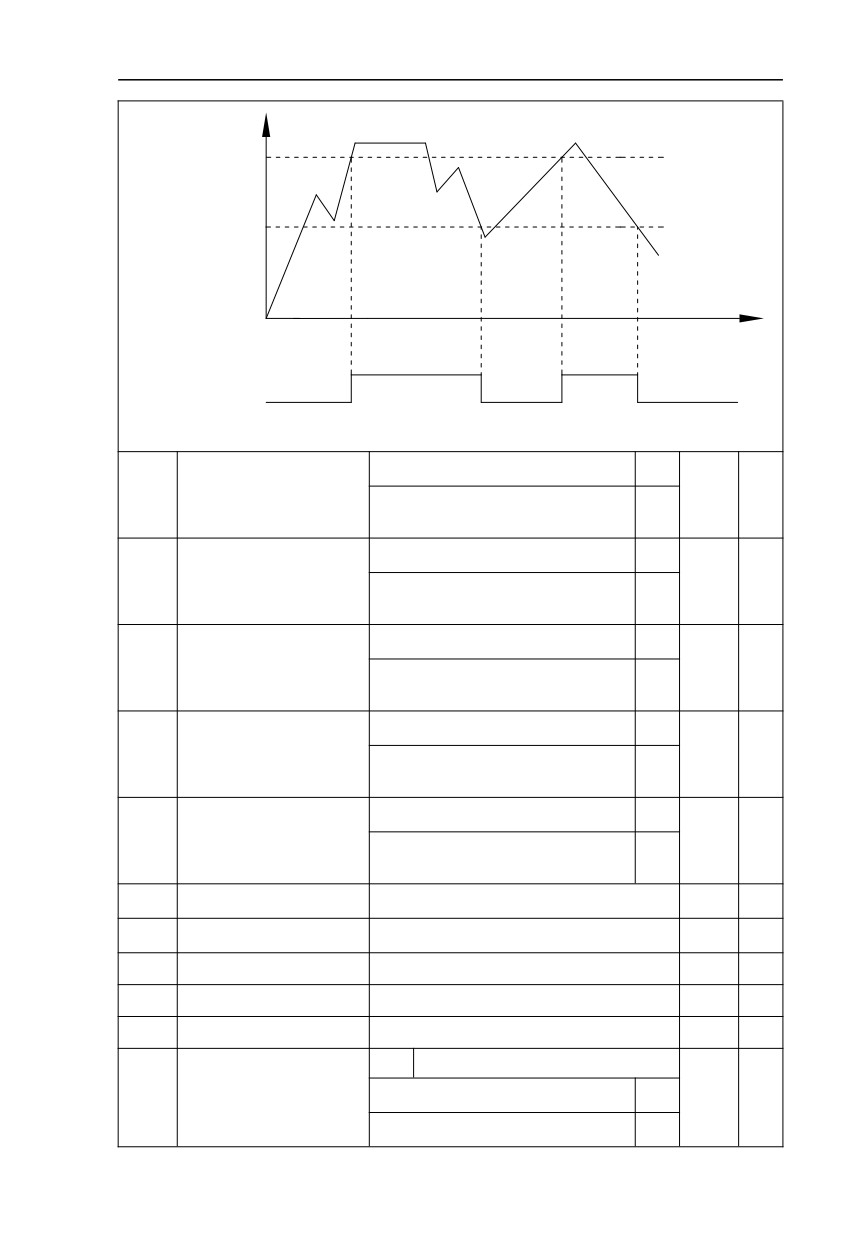
AI is used as DI for this function group. AI input voltage is greater than 7V, corresponding AI terminal
state is high level. AI input voltage is less than 3V, corresponding AI terminal state is low level. 3V~7V for
hysteresis loop .
Whether AI (as DI) high level valid or low level valid is determined through function code A1.10. For
AI(as DI) function settings, they are same with common DI settings, for details please refer to F4 group .
Fig. 5-31 takes AI input voltage as an example, explains the relationship between AI input voltage and
corresponding DI state:
106
Section V. Parameter Function Table
AI input voltage
DC7V
DC3V
t
ON
ON
OFF
AI terminal status
Fig.5-31AI terminal valid state schematic diagram
Short circuit with physics DIx internals
0
A1.11
Virtual VDO output function
0
☆
See F5 group for physics DO output
1~40
selection
Short circuit with physics DIx internals
0
A1.12
Virtual VDO2 output function
0
☆
See F5 group for physics DO output
1~40
selection
Short circuit with physics DIx internals
0
A1.13
Virtual VDO3 output function
0
☆
See F5 group for physics DO output
1~40
selection
Short circuit with physics DIx internals
0
A1.14
Virtual VDO4 output function
0
☆
See F5 group for physics DO output
1~40
selection
Short circuit with physics DIx internals
0
A1.15
Virtual VDO5 output function
0
☆
See F5 group for physics DO output
1~40
selection
A1.16
VDO output delay time
0.0s~3600.0s
0.0s
☆
A1.17
VDO2 output delay time
0.0s~3600.0s
0.0s
☆
A1.18
VDO3 output delay time
0.0s~3600.0s
0.0s
☆
A1.19
VDO4 output delay time
0.0s~3600.0s
0.0s
☆
A1.20
VDO5 output delay time
0.0s~3600.0s
0.0s
☆
1bit
VDO
VDO output terminal valid
A1.21
Positive logic
0
00000
☆
state selection
Negative logic
1
107
Section V. Parameter Function Table
10bit
VDO2
Positive logic
0
Negative logic
1
100bit
VDO3
Positive logic
0
Negative logic
1
1000
VDO4
bit
Positive logic
0
Negative logic
1
10000
VDO5
bit
Positive logic
0
Negative logic
1
Virtual digit output function , which is similar with control board DO output function , can be used to
cooperate with virtual digit input VDIx, to realize some simple logic control.
When virtual VDOx output function selecting 0, VDO~VDO5 output states is determined by input
states of X1~X5 on the keyboard.VDOx and DIx one-to-one corresponding.
When virtual VDOx output function selecting non-zero digits, VDOx function setting and use
method are same with F5 group DO output relevant parameters, for details please refer to F5 group.
Similarly, VDOx output valid state can choose positive or negative logic, and set through A1.21.
For VDOx use reference , please refer to applications for VDIx use .
5.20 The second motor control:A2.00-A2.65
HV610C can switch operation between 4 motors. The 4 motors could set motor nameplate
parameters, tune motor parameters, use V/F control or vector control, set encoder relating
parameters and set V/F control or vector control relating parameters respectively.
Groups of A2 、 A3 、 A4 are corresponding to motor2 、 motor3 、 motor4 respectively. And
the layout of the 3 groups of function codes are completely consistent .
For details please refer to relating parameters of motor1.
Description/
FactoryChange
Code
Setting Range
Keyboard Display
Setting
Limit
General asynchronous motor
0
A2.00
Motor type selection
Variable frequency asynchronous motor
1
0
★
Permanent magnet synchronous motor
2
A2.01
Rated power
0.1kW~1000.0kW
-
★
A2.02
Rated voltage
1V~2000V
-
★
0.01A~655.35A(Inverter power <=55kW)
A2.03
Rated current
-
★
0.1A~6553.5A(Inverter power >55kW)
108
Section V. Parameter Function Table
A2.04
Rated frequency
0.01Hz~maximum frequency
-
★
A2.05
Rated Speed
1rpm~65535rpm
-
★
Asynchronous motor stator
0.001Ω~65.535Ω(Inverter power <=55kW)
A2.06
-
★
resistance
0.0001Ω~6.5535Ω(Inverter power >55kW)
Asynchronous motor rotor
0.001Ω~65.535Ω(Inverter power <=55kW)
A2.07
-
★
resistance
0.0001Ω~6.5535Ω(Inverter power >55kW)
Asynchronous motor leakage
0.01mH~655.35mH(Inverter power <=55kW)
A2.08
-
★
inductance
0.001mH~65.535mH(Inverter power >55kW)
Asynchronous motor mutual
0.1mH~6553.5mH(Inverter power <=55kW)
A2.09
-
★
inductance
0.01mH~655.35mH(Inverter power >55kW)
Asynchronous motor no load
0.01A~A2.03(Inverter power <=55kW)
A2.10
-
★
current
0.1A~A2.03(Inverter power >55kW)
A2.27
Encoder pulses number
1~65535
2500
★
ABZ incremental encoder
0
UVW incremental encoder
1
A2.28
Encoder type
Rotary transformer
2
0
★
Sine/cosine encoder
3
UVW encoder
4
Local PG
0
A2.29
Speed feedback PG selection
Expansion PG
1
0
★
PULSE pulse input(X5)
2
ABZ incremental encoder AB
Forward
0
A2.30
0
★
phase
Reserve
1
A2.31
Encoder installation angle
0.0°~359.9°
0
0
★
Forward
0
A2.32
UVW phase sequence
0
★
Reverse
1
A2.33
UVW encoder offset angle
0.0°~359.9°
0.00
★
A2.34
Rotary transformer pole pairs
1~65535
1
★
No action
0.0s
A2.36
PG dropped inspection time
0.0s
★
0.1s~10.0s
0.1s
No operation
0
Asynchronous static tuning
1
A2.37
Tuning selection
Asynchronous complete tuning
2
0
★
Synchronous static tuning
11
Synchronous complete tuning
12
A2.38
Speed loop proportional gain 1
1~100
30
☆
109
Section V. Parameter Function Table
A2.39
Speed loop integration time1
0.01s~10.00s
0.50s
☆
A2.40
Switching frequency1
0.00~A2.43
5.00Hz
☆
A2.41
Speed loop proportional gain 2
0~100
20
☆
A2.42
Speed loop integration time 2
0.01s~10.00s
1.00s
☆
A2.43
Switching frequency 2
A2.40~maximum output frequency
10.00Hz
☆
A2.44
Vector control slip gain
50%~200%
150%
☆
A2.45
Speed-loop filtering time
0.000s~0.100s
0.000s
☆
A2.48 setup
0
AI1
1
AI2
2
Torque upper limit source in
AI3
3
A2.47
0
☆
speed control mode
PULSE setup
4
Communication setup
5
MIN(AI1,AI2)
6
MAX(AI1,AI2)
7
Torque upper limit digital
A2.48
setup in speed control
0.0%~200.0%
150.0%
☆
mode
Excitation regulation
A2.51
0~60000
2000
☆
proportional gain
Excitation regulation
A2.52
0~60000
1300
☆
integration gain
Torque requlation
A2.53
0~60000
2000
☆
proportional gain
Torque regulation
A2.54
0~60000
1300
☆
integration gain
1bit
Integration separation
Speed loop integration
A2.55
Invalid
0
0
☆
attribute
Valid
1
Speed sensorless vector control(SVC)
0
A2.61
Motor2 control mode
Speed sensor vector control(FVC)
1
0
★
V/F control
2
Same with the first motor
0
Motor 2 acc./dec. time
Acceleration time1
1
A2.62
0
☆
selection
Acceleration time 2
2
Acceleration time 3
3
110
Section V. Parameter Function Table
Acceleration time 4
4
Auto torquehoist
0.0%
A2.63
Motor 2 torque hoist
-
☆
0.1%~30.0%
Motor 2 oscillation
A2.65
0~100
-
☆
suppression gain
5.21 The third motor control: A5.00-A5.09
Description/
FactoryChange
Code
Setting Range
Keyboard Display
Setting
Limit
DPWM switching frequency
A5.00
0.00Hz~15.00Hz
12.00Hz
☆
upper limit
A5.00 is only valid for VF control mode. In asynchronous motor VF running mode, square wave
determine the continuous modulation mode. Wave value < A5.00 : 7-stage continuous modulation
mode. Wave value>A5.00:5-stage continuous modulation mode.
In 7-stage continuous modulation mode, inverter switch loss is relatively big, but current ripple is
small. In 5-stage continuous modulation mode, inverter switch loss is relatively small, but current ripple
is big. High frequency may lead to motor operation instability, generally there is no need of modification.
For VF operation instability please refer to F3.11. For inverter loss and temperature rise please
refer to F0.15.
Asynchronous modulation
0
A5.01
PWM modulation mode
0
☆
Synchronous modulation
1
This parameter is only valid for VF control mode. Asynchronous modulation refers to carrier
frequency that linear changes with output frequency, and ensure that the ratio of them (carrier ratio)
remains the same. Generally high output frequency is benefit for output voltage quality.
Generally, synchronous modulation is not needed at low frequencies ( below 100Hz), because the
ratio of carrier frequency and output frequency is relatively high,asynchronous modulation advantage is
more obvious.
When running frequency is greater than 85Hz, synchronous modulation is valid. And fixed as
asynchronous modulation mode when below this frequency.
Dead-zone compensation
No compensation
0
A5.02
1
☆
mode selection
Compensation mode 1
1
Generally speaking , A5.02 needs not to be modified. Only when the output voltage waveform quality
has special requirements or motor appears abnormal phenomenon would users switch the compensation
mode.
Random PWM invalid
0
A5.03
Random PWM depth
0
☆
PWM carrier frequency random depth
1~10
Set the random PWM, monotonous and harsh electromagnetic noise can be changed to the
heterogeneous and soft, the external electromagnetic interference can be effectively reduced.
0
indicates that the PWM is invalid. Different random PWM depth represents different regulation effect.
Invalid
0
A5.04
Rapid current-limiting enable
1
☆
Valid
1
Enable the rapid current-limiting function so as to minimize inverter overcurrent protection fault and
111
Section V. Parameter Function Table
make the inverter work normally.
If the inverter long time continuous staying in rapid current-limiting state, it may occur overheating
fault, which is not allowed during operation. Fault alarm of long time rapid current-limiting is 40= Err40 ,
which refers to inverter overload and necessary stop.
Current detection
A5.05
0~100
5
☆
compensation
It is used to set inverter current detection compensation. Excessive setting may lead to decrease of
control performance.Generally do not need to be modified.
A5.06
Under-voltage point setup
60.0%~140.0%
100.0%
☆
A5.06 is used to set value of inverter under-voltage fault 9= E.LU. Different voltage level of 100.0%
corresponds to different voltage point,respectively:
Single phase 220V or three-phase 220V:220V
Three-phase 380V:350V
Three phase 480V:450V
Three-phase 690V:650V
No optimization
0
SVC optimization mode
A5.07
Optimization mode 1
1
1
☆
selection
Optimization mode 2
2
0:No optimization
1: Optimization mode 1
It is used when there is high torque control linearity requirements.
2: Optimization mode 2
It is used when there is high speed stability requirement.
A5.08
Dead zone time adjustment
100%~200%
150%
☆
This parameter is set according to 1140V voltage level. By adjusting the value can improve the
voltage effective use rate. Users are not suggested to modify.
A5.09
Overvoltage point setup
200.0V~2500.0V
810.0V
☆
A5.09 is over-voltage point set through software, which is not related
to
hardware overvoltage
point.
5.22 AI curve setup: A6.00-A6.29
Description/
FactoryChange
Code
Setting Range
Keyboard Display
Setting
Limit
A6.00
AI curve 4 minimum input
-10.00V~A6.02
0.00V
☆
AI curve
4 minimum input
A6.01
-100.0%~100.0%
0.0%
☆
corresponding setup
AI curve
4inflection point
1
A6.02
A6.00~A6.04
3.00V
☆
input
AI curve 4 inflection point 1
A6.03
-100.0%~100.0%
30.0%
☆
input corresponding setup
AI curve 4 inflection point 2
A6.04
A6.02~A6.06
6.00V
☆
input
AI curve 4 inflection point 2
A6.05
-100.0%~100.0%
60.0%
☆
input corresponding setup
A6.06
AI curve 4 maximum input
A6.06~10.00V
10.00V
☆
112
Section V. Parameter Function Table
AI curve 4 maximum input
A6.07
-100.0%~100.0%
100.0%
☆
corresponding setup
A6.08
AI curve 4 minimum input
-10.00V~A6.10
-10.00V
☆
AI curve
5 minimum input
A6.09
-100.0%~100.0%
-100.0%
☆
corresponding setup
AI curve 5 inflection point 1
A6.10
A6.08~A6.12
-3.00V
☆
input
AI curve 5 inflection point 1
A6.11
-100.0%~100.0%
-30.0%
☆
input corresponding setup
AI curve 5 inflection point 2
A6.12
A6.10~A6.14
3.00V
☆
input
AI curve 5 inflection point 2
A6.13
-100.0%~100.0%
30.0%
☆
input corresponding setup
A6.14
AI curve 5 maximum input
A6.12~10.00V
10.00V
☆
AI curve 5 maximum input
A6.15
-100.0%~100.0%
100.0%
☆
corresponding setup
Function of curve 4 and curve 5 are similar with curve 1~curve 3’s. Curve 1~curve 3 are straight
lines, while curve 4 and curve 5 are 4-point curves which could realize more flexible correspondence.
Analog input
100%
corresponding setting
AI maximum input
corresponding setting
AI inflection point 1
corresponding setting
AI input voltage
AI inflection point 2
0V(0mA)
AI inflection point 1
10V(20mA)
AI inflection point 2
corresponding setting
AI minimum input
corresponding setting
-100%
Fig.5-32Curve4 and curve 5 schematic diagram
Notice : When setting curve 4 and curve 5, minimum input voltage, inflection point 1 voltage,
inflection point 2 voltage and maximum voltage must be increased in turn.
A6.24
AI1 set hopping point
-100.0%~100.0%
0.0%
☆
A6.25
AI1 set hopping amplitude
0.0%~100.0%
0.5%
☆
A6.26
AI2 set hopping point
-100.0%~100.0%
0.0%
☆
A6.27
AI2 set hopping amplitude
0.0%~100.0%
0.5%
☆
A6.28
AI3 set hopping point
-100.0%~100.0%
0.0%
☆
A6.29
AI3 set hopping amplitude
0.0%~100.0%
0.5%
☆
113
Section V. Parameter Function Table
Analog input AI1~AI3 of HV610C are all provided with hopping function for set value.
Hopping frequency refers to fixing of analog corresponding setup to the value of hopping point
when analog corresponding setting varies within jump point upper/lower limit.
E.g:
Voltage of analog input AI1 is in 5.00V fluctuation, which range is 4.90V~5.10V. Minimum input
0.00V corresponding to 0.0%, while maximum input 10.00V corresponding to 100.%.The corresponding
setting of AI1 fluctuates between 49.0%~51.0%.
Set A5.16 to 50.0% and A5.17 to 1.0%, after hopping function processing, AI1 is fixed as 50.0%. In
this way, AI1 is converted into a stable input, and fluctuation is eliminated.
5.23 User programmable card parameters: A7.00-A7.09 Reserved
5.24 Point to point communication:A8.00-8.11
Description/
FactoryChange
Code
Setting Range
Keyboard Display
Setting
Limit
Invalid
0
Master slave control
A8.00
0
☆
function selection
Valid
1
Master
0
A8.01
Master slave selection
0
☆
slave
1
0 bit
Do not follow the Master
0
command
follow the Master command
1
10 bit
Do not send fault
0
Master slave information
A8.02
information
011
☆
exchange
send fault information
1
100 bit
Do not warning when slave
0
off line
warning when slave off line
1
Master slave control frame
0
A8.03
Message frame selection
0
☆
Droop control frame
1
Receive data zero
-100.00%~100.00%
A8.04
0.00
★
offsettorque
A8.05
Receive data gain torque
-10.00~100.0
1.00
★
Communication interrupt
0.0s~10.0s
A8.06
1.0s
☆
detection time
Communication Master
0.001s~10.000s
A8.07
0.001
☆
data transmission cycle
114