HNC-8 System Operating. Manual (Milling Machine) V2.4 Series - page 6
HNC-8 System Operating Manual (Milling Machine)
7 Auto Operation
7.1 Auto Operation
7.1.1 Load Machining Program
Machining program can be loaded only under "Machining" function set. Although new programs can be created
under "Program" function set, the interface will switch to "Machining" function set when this operation is
conducted and it cannot be loaded as machining program automatically
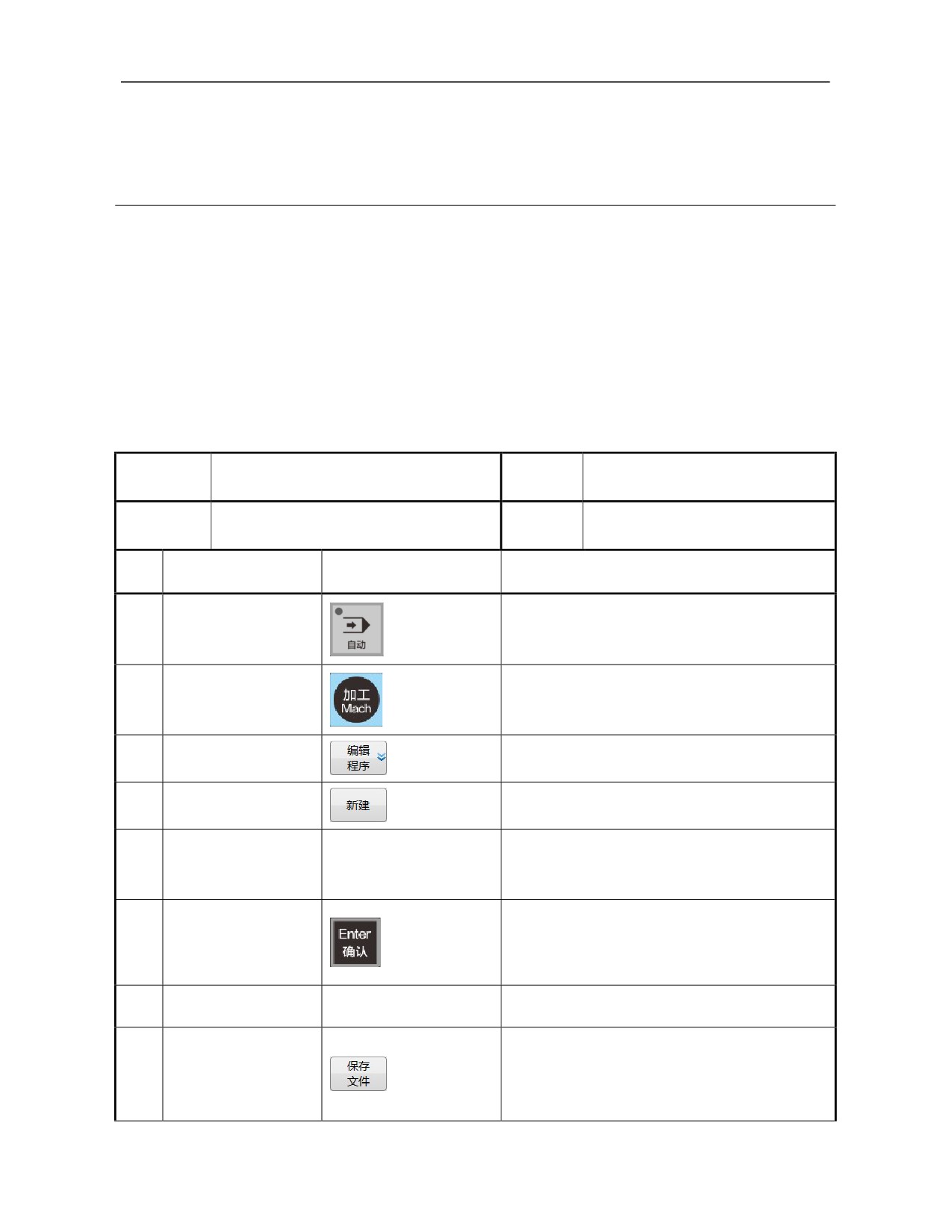
7.1.1.1 Load a new program as machining program
Operation
Working
Load a new program as machining program
Auto, single block, jog
name
mode
Basic
Create new programs under "Machining"
Display
3.2.3 "Edit program" sub-interface
requirements
function set
interface
SN
Operation steps
Key
Description
1
Press 【Auto】
Maintain the original interface
2
Press 〖Machining〗
Default interface, main menu
The cursor enters the loaded program editing
3
Press 『Edit program』
area
4
Press 『New』
Enter a new file name, such as “nc123”
5
(Enter a file name)
---
Address word of the new file name is O and
needs not inputted
Confirm the input, file name is Onc123
6
Press 「Enter」
The cursor enters the editing area
7
(Edit program)
---
Edit program and complete
The newly edited program is loaded as the
machining program immediately
8
Press 『Save file』
A prompt message File has been saved will be
given
126
HNC-8 System Operating Manual (Milling Machine)
Note:
After the new program is saved under "Machining" function set,
it can be loaded as current machining program automatically
The new program cannot be loaded as machining program under
"Program" function set.
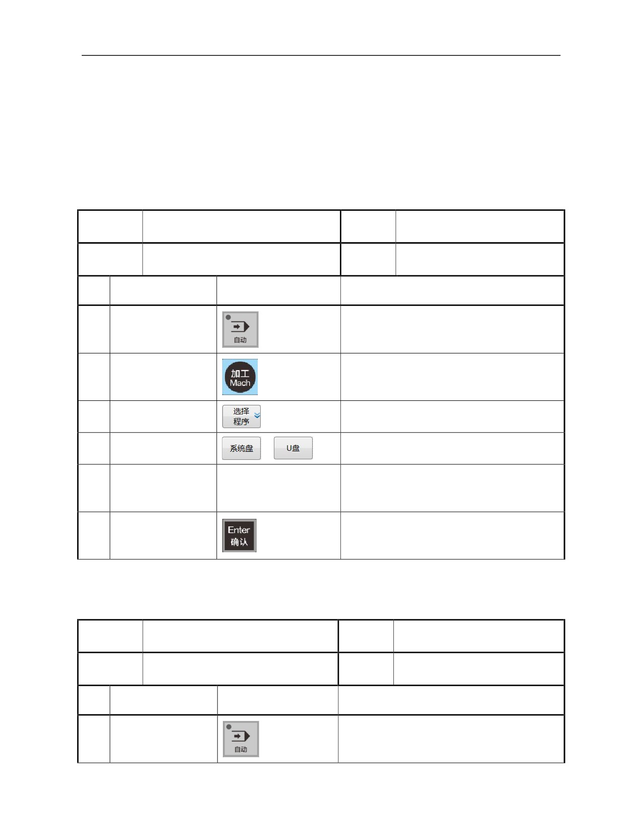
7.1.1.2 Load existing programs as machining program
Operation
Load existing programs as machining
Working
Auto, single block, jog
name
program
mode
Basic
The program to be loaded has already
Display
3.2.2 "Select program" sub-interface
requirements
existed in the disk
interface
SN
Operation steps
Key
Description
1
Press 【Auto】
Maintain the original interface
2
Press 〖Machining〗
Default interface, main menu
Press
『 Select
3
Search programs as per 6.1.2
program』
Press 『System disk』,
Select system disk/USB flash disk/network
4
etc.
disk/user disk
Select programs to be loaded as "Current
(Search
loading
5
---
machining program"
program)
Search programs as per 6.1.1
6
「Enter」
Loading is completed
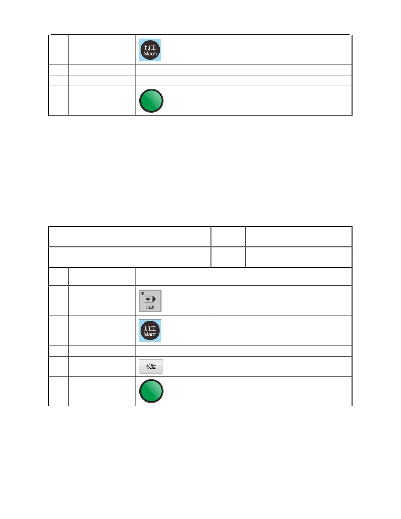
7.1.2 Program Run
Operation
Working
Program run
Auto
name
mode
Basic
Display
Machining program has been loaded
3.2 "Machining" function set interface
requirements
interface
SN
Operation steps
Key
Description
1
Press 【Auto】
Maintain the original interface
127
HNC-8 System Operating Manual (Milling Machine)
2
Press 〖Machining〗
Default interface, main menu
3
(Loading program)
---
Load machining program as per 7.1.1
4
(Safety inspection)
---
Complete deceleration and lock
Run a program automatically
5
Press [Cycle start]
Note:
Before running a new program automatically, complete tool
setting;
Although automatic machining is not conducted under
"Machining" function set, it is easier to operate and observe
under "Machining" function set.
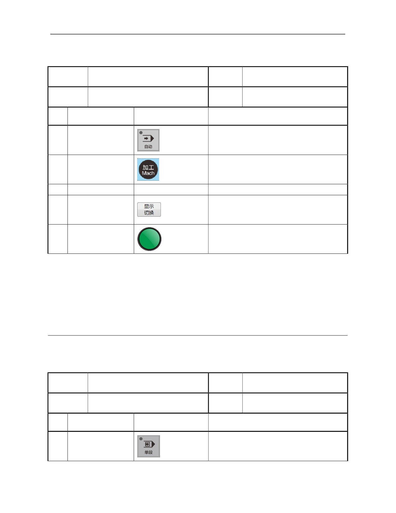
7.1.3 Program Verify
Operation
Working
Program verify
Auto, single block
name
mode
Basic
Display
Machining program has been loaded
3.2.4 "Verify program" sub-interface
requirements
interface
SN
Operation steps
Key
Description
1
Press 【Auto】
Maintain the original interface
2
Press 〖Machining〗
Default interface, main menu
3
(Loading program)
---
Load machining program as per 7.1.1
Working mode is displayed as "Verify"
4
Press 『Verify』
The『Verify』 soft key is highlighted.
Exit the verification after automatic operation
5
Press [Cycle start]
Press [Reset] to exit the verification
128
HNC-8 System Operating Manual (Milling Machine)
7.1.4 Program Graphics Simulation
Operation
Working
Program graphics simulation
Auto, single block
name
mode
Basic
Display
Machining program has been loaded
3.2 "Machining" function set interface
requirements
interface
SN
Operation steps
Key
Description
1
Press 【Auto】
Maintain the original interface
2
Press 〖Machining〗
Default interface, main menu
3
(Loading program)
---
Load machining program as per 7.1.1
Press this key once, and the interface is
Press
『 Display
4
switched
switch』
Select “Graphics+ program” interface
Conduct automatic operation and realize
5
Press [Cycle start]
graphics simulation
Note
For size and position of workblank used for graphics simulation,
refer to the description of 3.2.7 "Graphics setup" sub-interface.
7.2 Automatic Operation Control
7.2.1 Single-block Operation
Operation
Working
Single-block operation
Single block
name
mode
Basic
Display
Complete loading of machining program
3.2 "Machining" function set interface
requirements
interface
SN
Operation steps
Key
Description
1
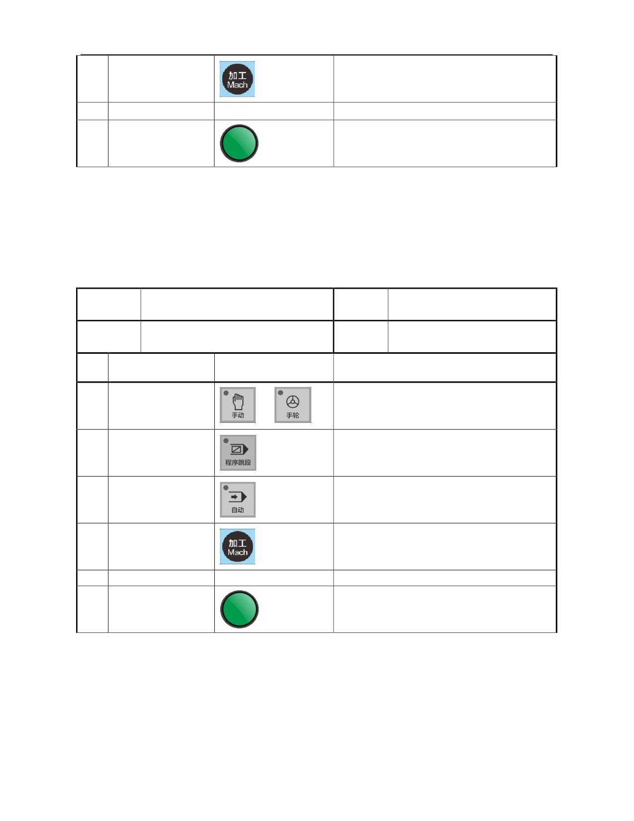
Press 【Single block】
Maintain the original interface
129
HNC-8 System Operating Manual (Milling Machine)
3
Press 〖Machining〗
Default interface, main menu
4
(Loading program)
---
Load machining program as per 7.1.1
5
Press [Cycle start]
Press Cycle start once to execute a block of
program, and cycle in turn
Note:
Like the auto operation mode, in the single block mode the
verification and simulation can also be performed.
7.2.2 Block Skip Operation
Operation
Working
Block skip operation
Auto, single block
name
mode
Basic
Program block number is prefixed with “/”,
Display
3.2 "Machining" function set interface
requirements
e.g.: /N1 X30 Z5
interface
SN
Operation steps
Key
Description
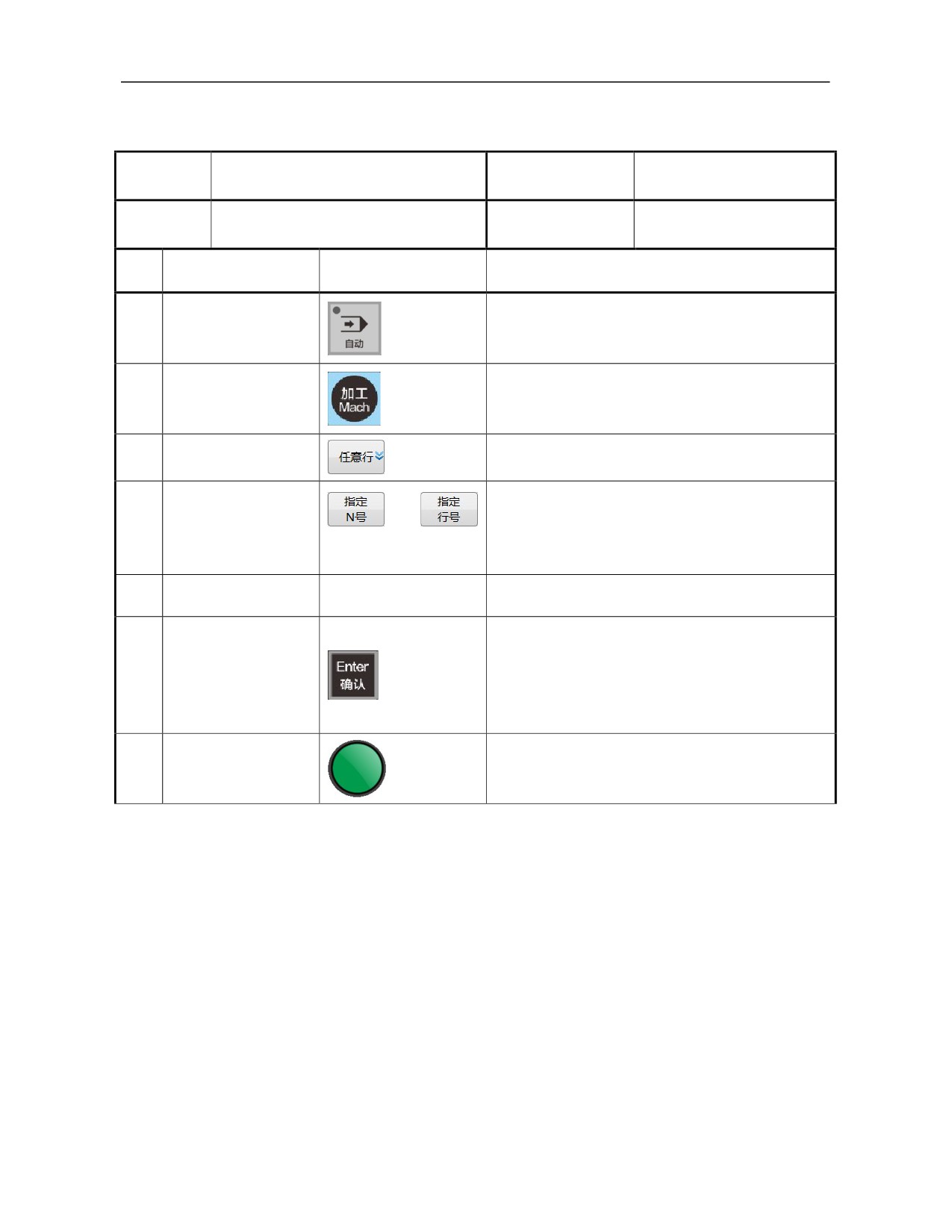
Press
【 Jog 】 or
Block skip operation function is set only under
1
【Handwheel】
jog, handwheel or incremental mode
or
Program blocks with the skip symbol will be
2
Press [Block skip]
skipped
3
Press 【Auto】
Maintain the original interface
4
Press 〖Machining〗
Default interface, main menu
5
(Loading program)
---
Load machining program as per 7.1.1
Skip the marked block during automatic
6
Press [Cycle start]
operation.
Note:
If program blocks with the skip symbol “/” are executed after
[Block skip] is pressed, the system skips over this line of
commands, and directly executes the next line of commands.
If the [Block skip] is not pressed, the system still executes this
line of commands in order.
130
HNC-8 System Operating Manual (Milling Machine)
7.2.3 Execute from Any Line
Operation
Execute from any line
Working mode
Auto, single block
name
Basic
3.2 "Machining" function set
Cannot start from the subprogram line
Display interface
requirements
interface
SN
Operation steps
Key
Description
1
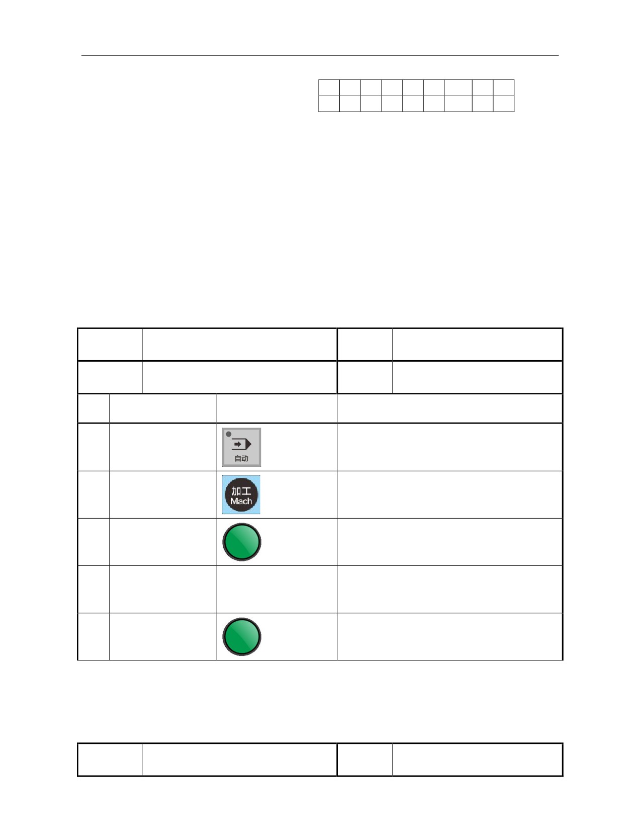
Press 【Auto】
Maintain the original interface
Default interface, main menu
2
Press 〖Machining〗
Correctly load the programs which need the any
line execution
3
Press 『Any line』
Enter the "Any line" submenu
Press
『 Specify line
Or
number 』
and
The indicator light lights off
4
『 Specify N
Suspend operation
number』
5
(Input line number)
---
Input a value, such as 8
Confirm the input
The cursor moves to the line before the inputted
6
Press 「Enter」
line
Move the cursor to the selected any line by
「Cursor」
7
Press [Cycle start]
Start to run from the specified line
Note:
"Any line mode selection" parameter 040113 can be set as 0-2 and
the function is shown below:
0: Non-scanning mode. The modal before the target line is not
inherited;
1: Scanning mode except Z axis. The modal before the target line is
inherited except Z axis mode;
2: Full scanning mode. The modal before the target line is inherited.
The parameter Any axis in-position sequence 040114 can set the
in-position sequence of each axis. The parameter is of the numerical
type. The corresponding relationship between the bit and the axis is
131
HNC-8 System Operating Manual (Milling Machine)
shown below:
1
2
3
4
5
6
7
8
9
X
Y
Z
A
B
C
U
V
W
XYZABCUVW from low bit to high bit. The larger the value is the
later the axis reaches in-position. 0 means the axis is not configured.
For milling machine, 040114=211 means X/Y axis moves to the right
position and then Z axis reaches the right position.
For milling machine, 040114=101, it means that X/Z arrives at the
right position simultaneously and Y does not move.
While using the "Designated N number" function, there should be
instruction address N at the block head.
7.2.4 Stop Operation
Operation
Working
Stop operation
Auto
name
mode
Basic
There is M00 "Stop operation" command in
Display
3.2 "Machining" function set interface
requirements
loading program
interface
SN
Operation steps
Key
Description
1
Press 【Auto】
Maintain the original interface
Default interface, main menu
2
Press 〖Machining〗
Load machining program correctly
3
Press [Cycle start]
The program is running
The program suspends its execution
(Execute
M00
4
----
Manual tool change and other operations can
command)
be executed
Continue running subsequent programs
5
Press [Cycle start]
7.2.5 Optional Stop
Operation
Working
Optional stop
Auto
name
mode
132
HNC-8 System Operating Manual (Milling Machine)
Basic
There is M01 "Optional stop" command in
Display
3.2 "Machining" function set interface
requirements
loading program
interface
SN
Operation steps
Key
Description
1
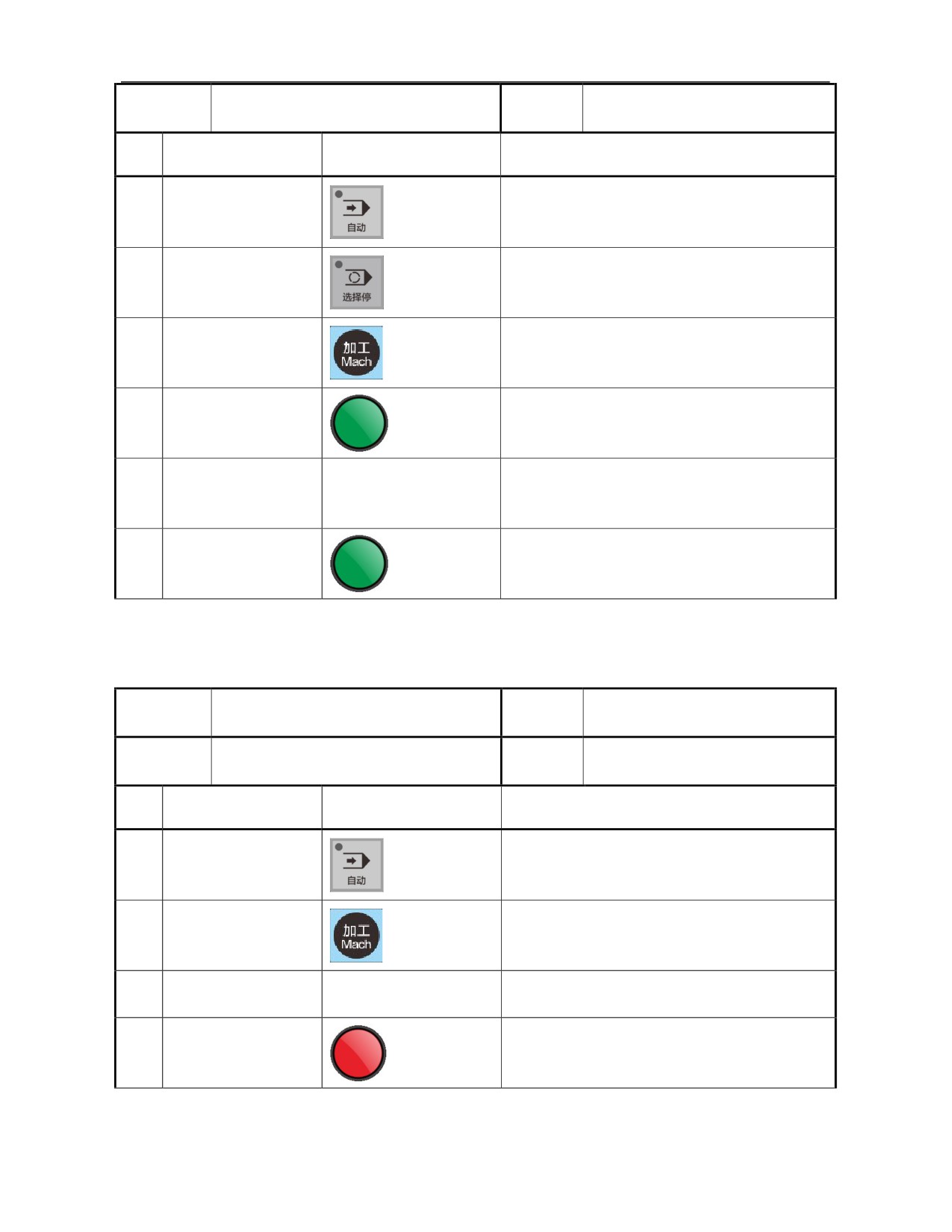
Press 【Auto】
Maintain the original interface
If this step is not executed, continuously run
2
Press [Optional stop]
the program
Default interface, main menu
3
Press 〖Machining〗
Load machining program correctly
4
Press [Cycle start]
The program is running
The program suspends its execution
(Execute
M01
5
----
If the step 2 is not executed, the program does
command)
not stop but runs continuously
Continue running subsequent programs
6
Press [Cycle start]
7.2.6 Dwell
Operation
Working
Dwell
Auto
name
mode
Basic
Display
The program continuously runs
3.2 "Machining" function set interface
requirements
interface
SN
Operation steps
Key
Description
1
Press 【Auto】
Maintain the original interface
2
Press 〖Machining〗
Default interface, main menu
(Running
the
3
---
The program is running
program)
The indicator light lights off
4
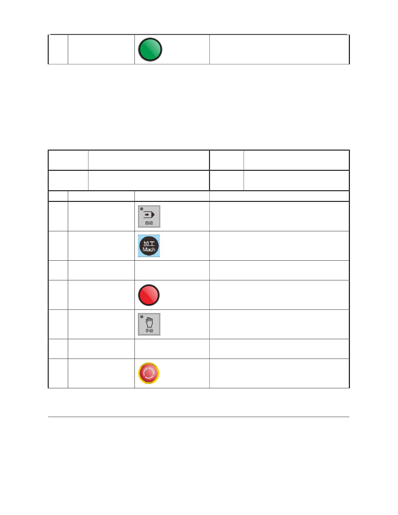
Press [Feed hold]
The operation is suspended
133
HNC-8 System Operating Manual (Milling Machine)
Continue the operation
5
Press [Cycle start]
Note:
During thread machining, feed hold cannot be validated
immediately, and it is not validated until thread instruction is
completed.
7.2.7 Terminate Operation
Operation
Working
Terminate operation
Auto
name
mode
Basic
Display
The program continuously runs
3.2 "Machining" function set interface
requirements
interface
SN
Operation steps
Key
Description
1
Press 【Auto】
Maintain the original interface
2
Press 〖Machining〗
Default interface, main menu
(Running the
3
---
The program is running
program)
The indicator light lights off
4
Press [Feed hold]
The operation is suspended
To close MST manually
5
Press 【Jog】
(Disable M and S
6
---
Disable MST manually
functions)
Press [Emergency
Terminate the operation
7
stop]
Reset
7.3 MDI Operation
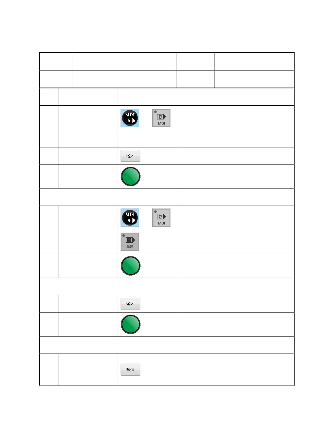
“MDI” function of HNC-8 system has two forms,
MDI key is the working mode key【MDI】 of MCP panel
MDI key is the function set key 〖MDI〗 of NC panel
The【MDI】 key of HNC-808DiM system is on MCP panel. Operation and
134
HNC-8 System Operating Manual (Milling Machine)
function of two types of "MDI" keys are basically identical.
Operation
MDI operation
Working mode
MDI
name
Basic
Display
The system can run normally
requirements
interface
SN
Operation steps
Key
Description
or
Enter the MDI interface and the main menu
1
Press 【MDI】
The cursor is in the editing area
2
(Edit MDI program)
---
Edit multiple lines at a time before operation
3
Press 『Input』
Input all programs in the editing area
The machine tool runs as per the input program
4
Press [Cycle start]
Programs in the editing area are reserved, even
though the interface is switched
5.1 To run MDI program in single block
or
Enter the MDI interface and the main menu
5.1.1
Press 【MDI】
The cursor is in the editing area
The indicator light of single-block mode lights
5.1.2
Press 【Single block】
up
The machine tool runs as per the input program
5.1.3
Press [Cycle start]
Programs in the editing area are reserved, even
though the interface is switched.
5.2 To rerun programs in the editing area
5.2.1
Press 『Input』
Repeat steps 3 and 4
5.2.2
Press [Cycle start]
---
5.2 To suspend a program
The machine tool stops operation and is at feed
hold status
5.3.1
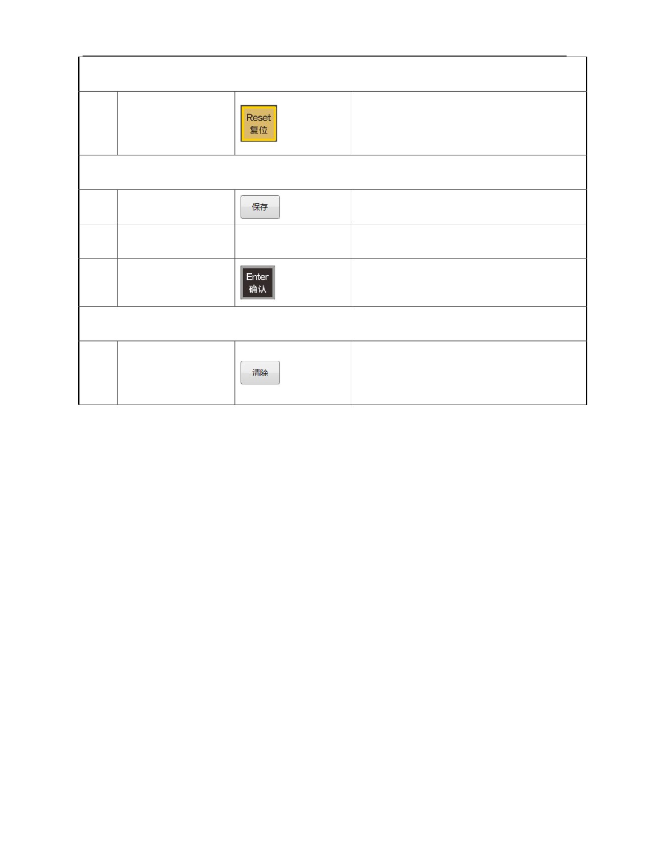
Press 『Dwell』
Press [Cycle start] to continuously run the
subsequent programs
135
HNC-8 System Operating Manual (Milling Machine)
5.3 To cancel this operation
This operation is canceled, and reenter to
resume operation
5.4.1
Press 「Reset」
Reset is not allowed during threading and
drilling
5.4 To save MDI program in the system disk
The input box gives a prompt message: Please
5.5.1
Press 『Save』
enter a file name
The program will be saved to PROG directory
5.5.2
(Enter a file name)
---
of the system disk
The program has been saved and a prompt
5.5.3
Press 「Enter」
message will be given
5.5 To clear programs in the MDI editing area at a time
Power off to clear programs in the MDI editing
area
5.6.1
Press 『Clear』
The interface is switched, the edited MDI
program cannot be cleared
Note:
When the parameter 000371 is set as 0, The MDI is the key mode
of MCP panel; when it is set as 1, it is the key mode of NC panel.
If【MDI】key is on the NC panel, “MDI” is the function set key.
There is an independent interface for the MDI working mode. If
the working mode is switched, the interface changes accordingly.
If〖MDI〗key is on the MCP panel, “MDI” is the working mode
key. This function is valid under auto mode or single block mode.
136
HNC-8 System Operating Manual (Milling Machine)
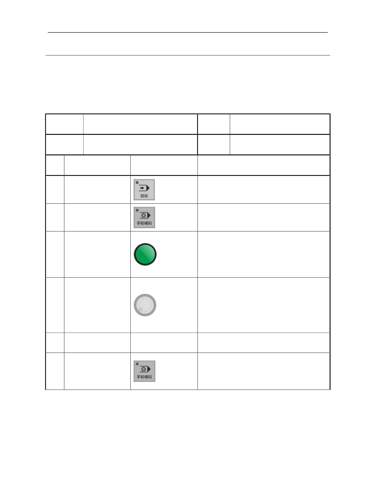
7.4 Handwheel Precutting
This function controls the machine tool axis to run as per the programmed
path through the MPG. It is often used to check whether tool setting is
correct when the tool approaches the workpiece in order to avoid
damaging the workpiece. This function is valid under automatic mode or
single block mode.
Operation
Working
Handwheel precutting
Auto
name
mode
Basic
The machining preparation is in the state of
Display
See Chapter 3 "Machining" function
requirements
automatic program running
interface
set interface
SN
Operation steps
Key
Description
This function can be executed under automatic
1
Press 【Auto】
operation
Press
[Handwheel
If this function is valid, the indicator light
2
simulation]
lights up
The commands run normally before the
machine tool axis moves, such as the spindle
3
Press [Cycle start]
rotation CW.
The machine tool axis does not move at this
moment
If the handwheel rotates clockwise, the
machine tool axis moves forward with the
program
4
(Rotate the handwheel)
If the handwheel rotates counterclockwise, the
machine tool axis moves backward with the
program
5
(Check tool position)
---
Visually inspect correctness of tool position
Function is released and the indicator light
Press
[Handwheel
lights off
6
simulation]
The machine tool continuously runs the
subsequent programs until shutdown
137
HNC-8 System Operating Manual (Milling Machine)
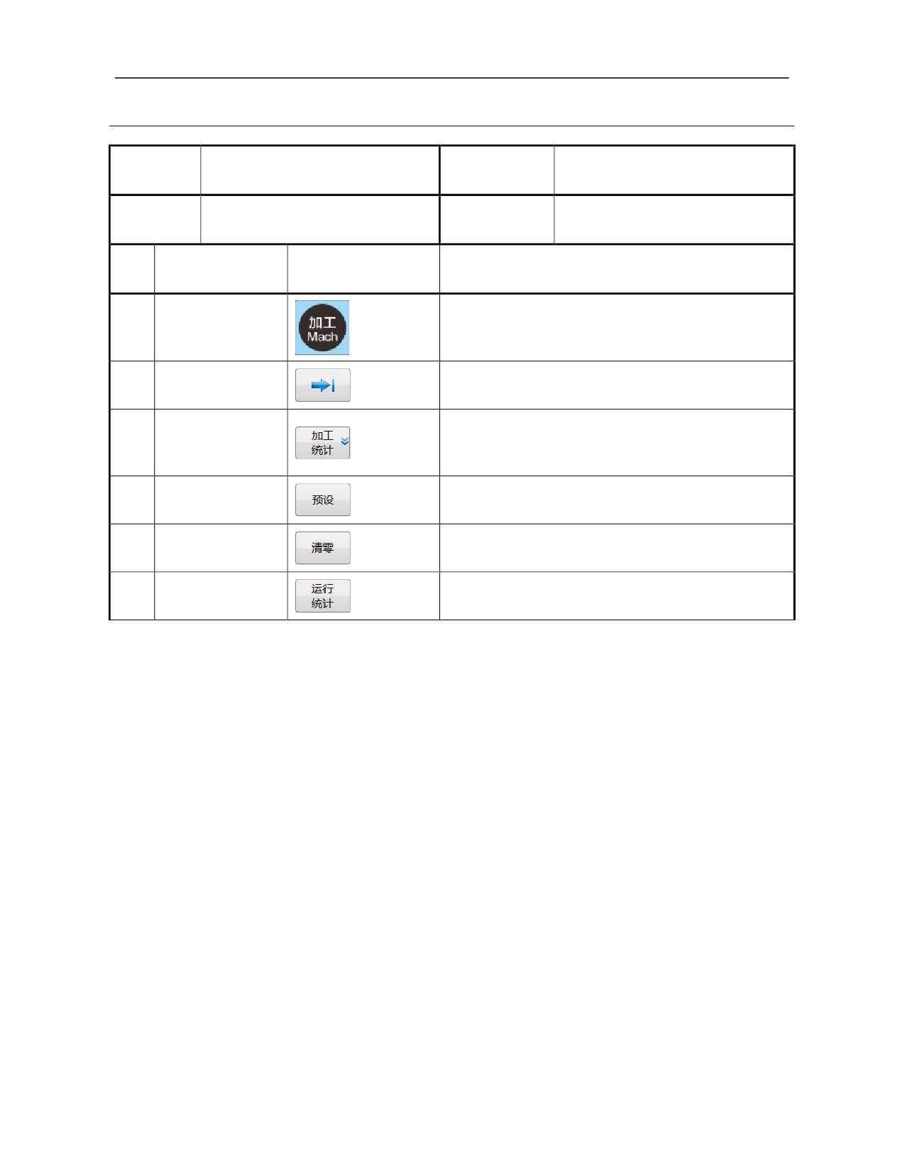
7.5 Machining Information Query
Operation
Auto, jog, handwheel, reference point
Machining information query
Working mode
name
return
Basic
Display
---
See Chapter 3 "Machining" interface
requirements
interface
SN
Operation steps
Key
Description
1
Press 〖Machining〗
Default interface, main menu
2
Press 『→』
Enter the extension menu
Enter the "Machining statistics" sub-interface
Press
『Machining
3
The system displays number of processed parts and
statistics』
information related to system operation time
4
Press 『Preset』
Set total number of processed parts needed, etc.
Reset time and number of processed parts
5
Press 『Reset』
Press
『 Operation
6
Export or eliminate machining information file
statistics』
138
8
Tool Setting and Machining Setup
Manual tool setting is completed mainly in "Coordinate system" and
"Tool compensation" sub-interfaces. For ease of user operation, the
system set two sub-interfaces in both "Machining" and "Setup" function
sets to reduce interface switching. The operating steps for both are
basically the same.
For some specific parts, the system can simplify manual tool setting
through "Workpiece measurement" function in "Setup" function set. This
function includes "Center measurement", "Plane measurement" and
"Circle center measurement" and is mainly used to set coordinates of X,
Y and Z axes automatically.
With the popularity of CNC machine tools, the application of tool setter
has become more widespread, and automatic tool setting has been
increasingly used. The system is configured with "Auto tool setting"
function in "Setup" function set, which can be used for automatic setup of
Z axis coordinates and tool length compensation.
8.1 Manual Tool Setting
Manual tool setting is taken as an example under "Setup" function set in
this quarter.
Operation
Working
Manual tool setting
Jog, handwheel
name
mode
3.2
"Coordinate system" and "Tool
Display
compensation" sub-interfaces under "Setup"
interface
function set
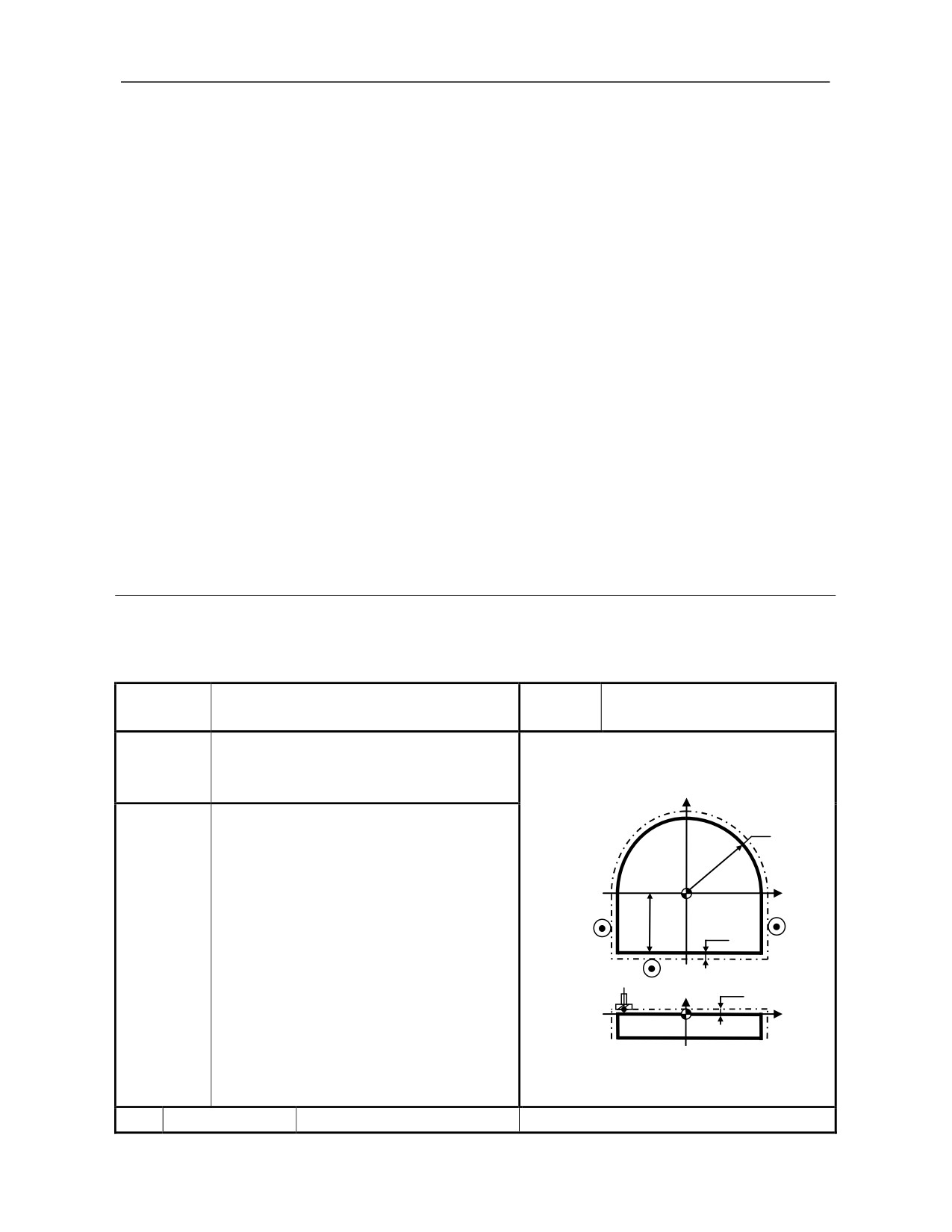
Y
1. Peripheral allowance is uniform and is
R10
0.6mm;
零
2. Allowance of the upper surface is 0.1mm;
件
3. Straight edge of the blank is basically
X
对
parallel to the coordinate axis;
A2
刀 A1
8
4. Roughing tool and finishing tool are
0.6
Basic
示
adopted, and the tool diameter is 10mm;
requirements
意
B
5. When A1 and A2 are the tool setting on X
图
0.1
C
Z
axis, the tool just touches the workpiece;
X
6. When B is the tool setting on Y axis, the
tools just touches the workpiece;
7. When C is the tool setting onZ axis, the tool
just touches the workpiece.
SN
Operation steps
Key
Description
139
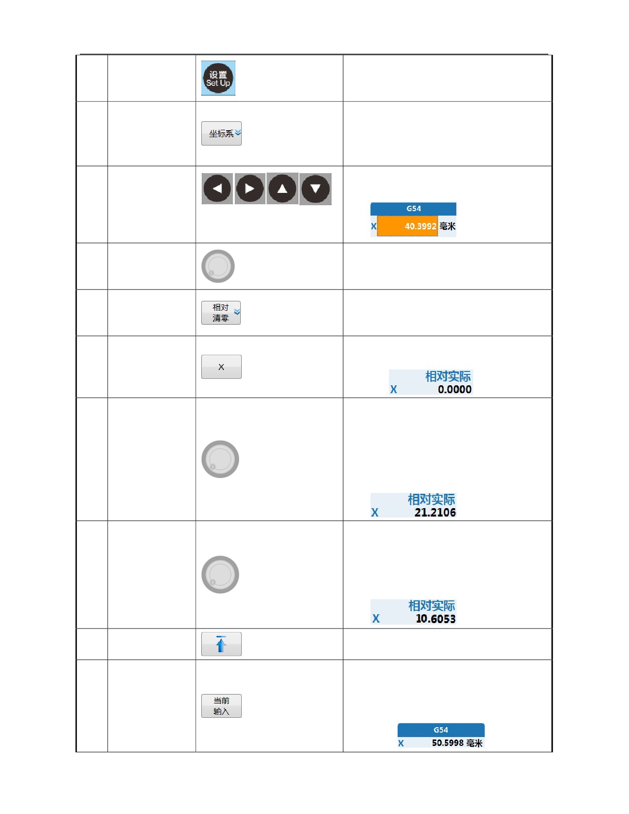
1
Press 〖Setup〗
Enter the "Setup" function interface
Press
『Coordinate system』 is the soft key of
2
『 Coordinate
level 1 menu;
system』
Select X axis coordinates of G54 using
Select coordinate
cursor as below:
axis
and tool
3
setting axis
(X
axis)
Move the tool to
The tool just touches the left edge of
4
A1 point with
workpiece (precutting mode);
handwheel
Switch the interface to "Relative clear"
Press
『 Relative
5
sub-interface;
clear』
Relative clear of X axis, and "Relative
actual" coordinate is displayed as 0;
6
Press 『X』
After avoiding the workpiece, the tool just
touches the right edge of workpiece;
Read "Relative actual" coordinate value. If
Move the tool to
it is
21.2106 (error of precutting position
7
A1 point with
value, cannot be greater than allowance
handwheel
value); at this time it is displayed as
Move to the A1A2 midpoint, namely half
of
"Relative
actual"
value
Move the tool to
21.2106/2=10.6053;
the
point
of
8
The midpoint of A1A2 is the workpiece
"Relative actual"
coordinate zero on C, and is displayed as
10.6053 of X axis
Return to the previous "Coordinate system"
9
Press 『↑』
sub-interface.
Press 『Current input』 to set machine
coordinate value of the tool as the
Press
『 Current
workpiece coordinate zero on X. Replace
10
input』
the original value, and display the present
value
140
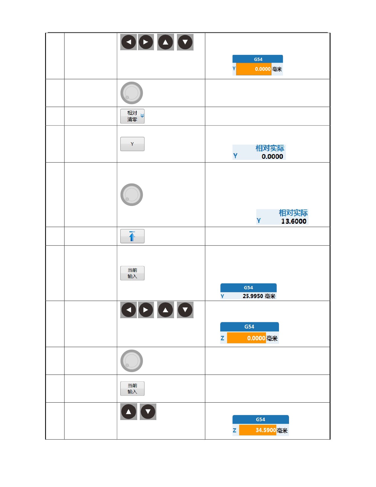
Select Y axis coordinates of G54 using
Select coordinate
cursor as below:
system and tool
11
setting axis
(Y
axis)
Move the tool to B
The tool just touches the lower edge of
12
point
with
workpiece (precutting mode)
handwheel
Press
『 Relative
Switch the interface to "Relative clear"
13
clear』
sub-interface;
Relative clear of Y axis, and "Relative
actual" coordinate is displayed as 0;
14
Press 『Y』
。
The distance between the workpiece
coordinate zero on Y and the tool is: The
Move the tool to
distance from the zero point to workpiece
the
point
of
15
edge
+ allowance
+ tool radius
"Relative actual"
8+0.6+10/2=13.6;
13.6 of Y axis
Displayed as:
Return to the previous "Coordinate system"
16
Press 『↑』
sub-interface.
After tool setting of workpiece zero on Y is
completed, record the machine coordinate
Press
『 Current
value on Y axis of current tool in the
17
input』
coordinate system.
Select Z axis coordinates of G54 using
Select coordinate
cursor as below:
axis
and tool
18
setting axis
(Z
axis)
Move the tool to C
The tool just touches the upper surface of
19
point
with
the workpiece (precutting mode)
handwheel
Record the machine coordinate value on Z
Press
『 Current
20
axis of current tool in the coordinate
input』
system .
Returning to Z axis coordinates
21
Press 「Cursor」
141
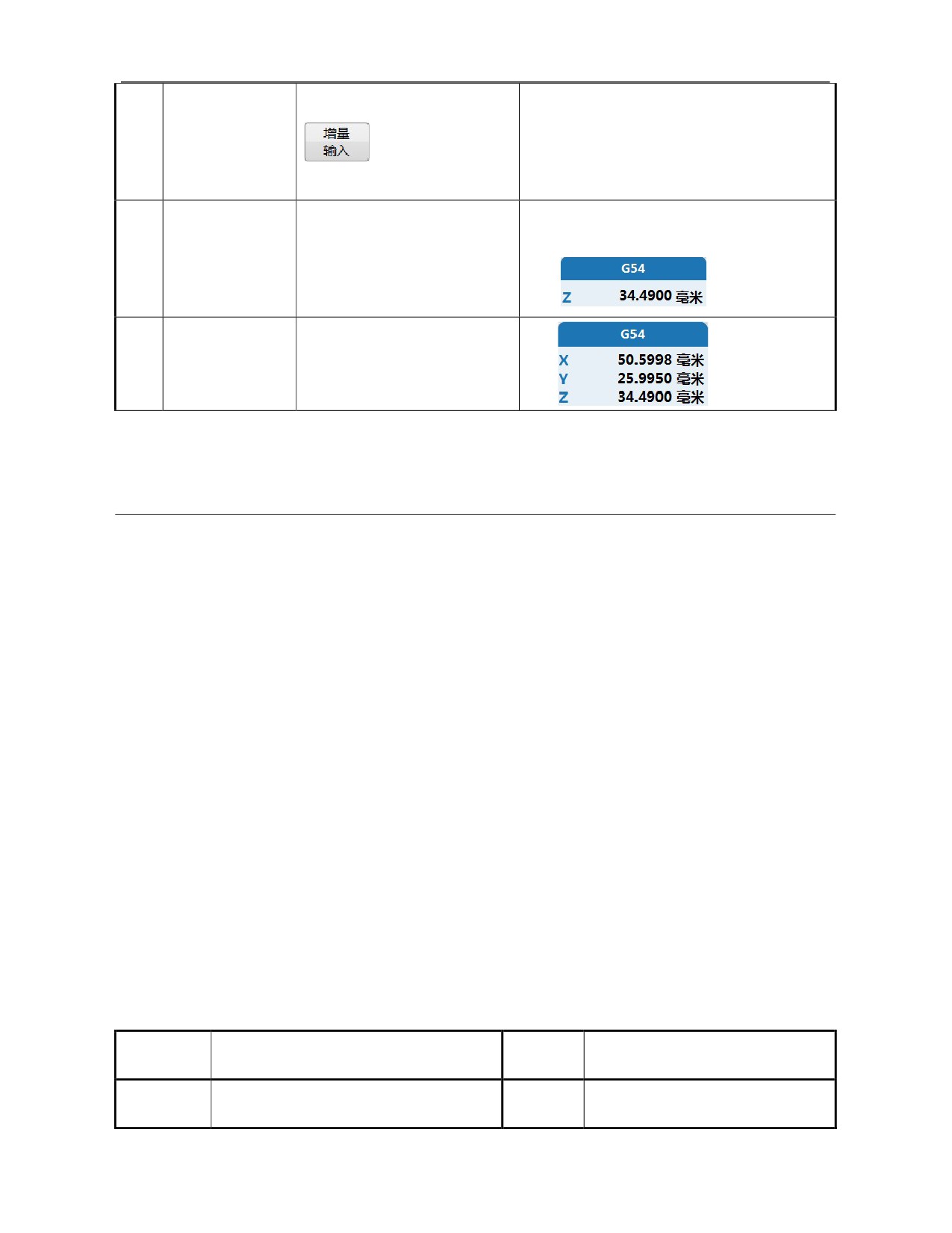
The workpiece zero is at the distance equal
to an allowance below the tool, -0.1mm.
Press
22
(The direction of the workpiece zero
『Incremental』
relative to the tool is opposite to the
direction of the work coordinate system)
Increase "-0.1"mm based on the above
value and confirm, it is displayed as
Input incremental
23
--
value “-0.1”
After tool setting
is completed, the
24
--
zero of G54 is
displayed
8.2 Workpiece Measurement
"Setup" function set supports the workpiece measurement function. This
function supports center measurement, plane measurement and circle
center measurement, and the measurement results are calculated and
saved in the selected coordinate system.
8.2.1 Center Measurement
When the zero of the workpiece coordinate system is set in the symmetric
central position of the workpiece, this tool setting mode is applicable. The
system reads the coordinate value of machine tool in the same axial
direction when the tool touches both ends of the workpiece, and then
calculates the value of the zero of workpiece coordinate.
For vertical machine tools, the Z axis direction of the workpiece is not
centered. Thus, move the tool to the workpiece zero(generally on the
upper surface of the workpiece) during precutting, and keep the tool
position unchanged while setting A and B points on the interface. At this
time, press the 『Read measurement』 to read the machine coordinate
value of the tool, and the point is set as the zero point value of the
workpiece.
Operation
Working
Center measurement
Jog, handwheel
name
mode
Basic
The system is allowed to run under jog
Display
See
Chapter
3
"Workpiece
requirements
mode and handwheel mode
interface
measurement" interface
142
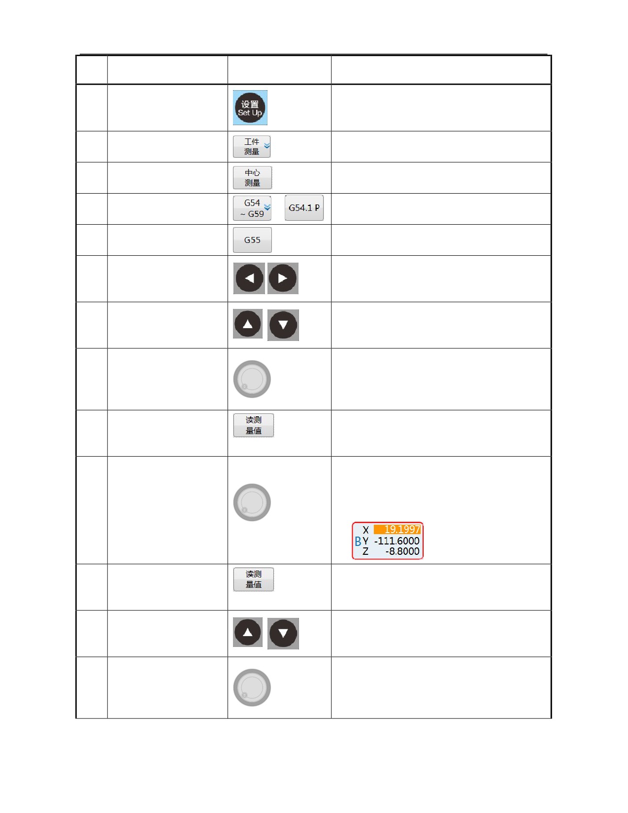
SN
Operation steps
Key
Description
Enter the main interface of "Setup" function
1
Press 〖Setup〗
set.
Press
『 Workpiece
Enter the "Workpiece measurement" function
2
measurement』
interface.
Press
『 Center
Switch to the center measurement workpiece
3
measurement』
interface.
4
Press 『G54-G59』
Select the type of coordinate system.
or
5
Press 『G55』
Select the coordinate system.
Press left and right
6
Select the point A for tool setting.
「Cursor」
Press up and down
7
Select the X coordinate axis;
「Cursor」
The tool just touches the left edge of workpiece
8
Move the tool to the left
blank (precutting mode);
size of the workpiece by
At this time, select point A corresponding to the
handwheel
left side of the workpiece.
Press
『 Read
The cursor skips to B point automatically on X
9
measurement』
axis
After avoiding the workpiece, the tool just
touches the right edge of workpiece blank;
10
Move the tool to the right
The error of precutting position cannot be
size of the workpiece by
greater than the allowance value.
handwheel
Press
『 Read
The cursor returns to A point automatically and
11
measurement』
the coordinate axis remains unchanged
Press up and down
12
Select Y coordinate axis;
「Cursor」
The tool just touches the rear edge of
13
Move the tool to the rear
workpiece blank precutting mode);
side of the workpiece by
Then, select the A point corresponding to the
handwheel
rear of workpiece.
143
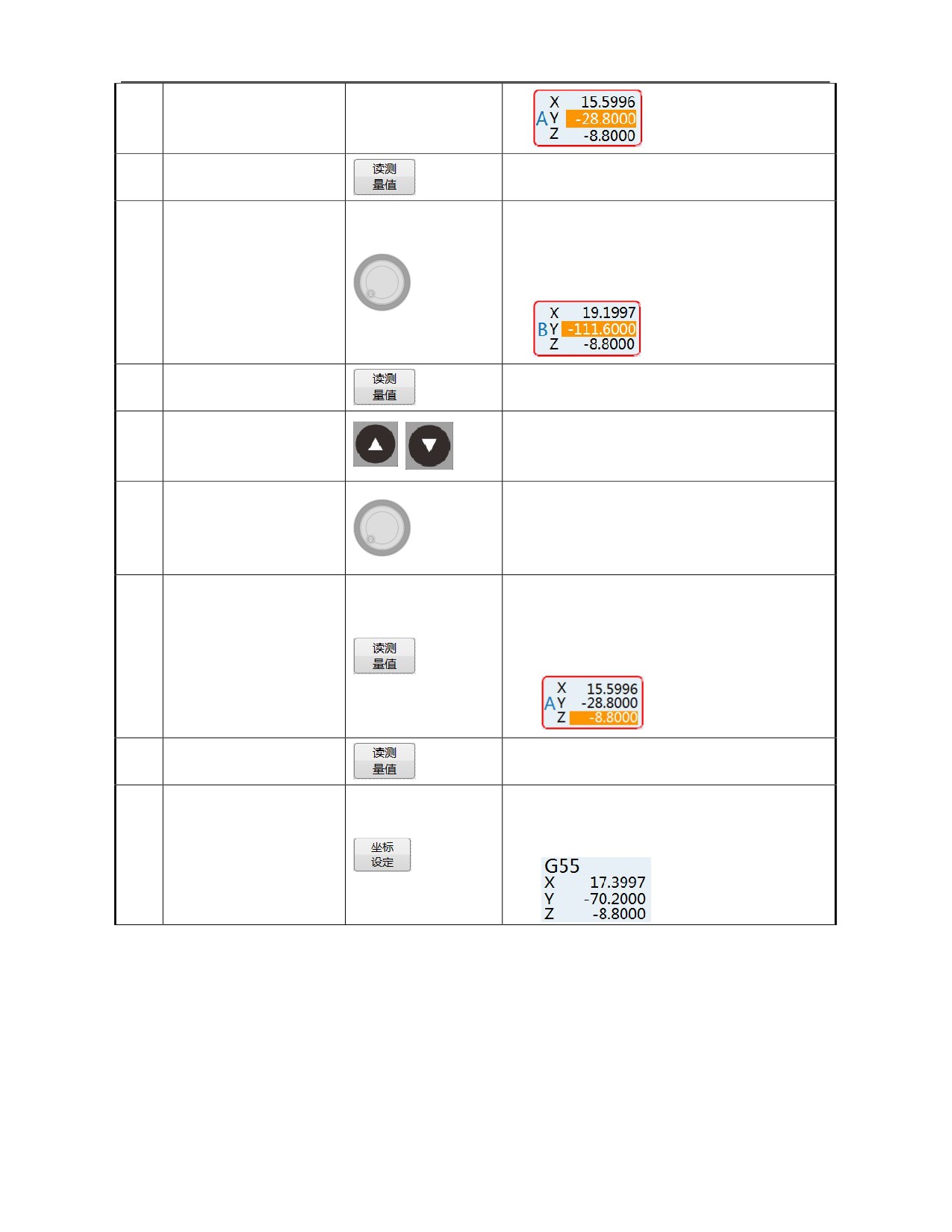
Press
『 Read
The cursor skips to B point automatically on Y
14
measurement』
axis
After avoiding the workpiece, the tool just
touches the front edge of workpiece blank;
15
The tool moves to the
The error of precutting position value cannot be
front side of the workpiece
greater than allowance value.
by handwheel
Press
『 Read
The cursor returns to A point automatically and
16
measurement』
the coordinate axis remains unchanged
Press up and down
17
Select Z coordinate axis;
「Cursor」
The tool just touches the upper surface of the
18
The tool moves to the
workpiece blank (precutting mode);
upper surface of the
Then, the upper surface of the workpiece is the
workpiece by handwheel
Z axis zero point of the workpiece.
The cursor skips to B point automatically on
(Z) axis;
Keep the tool position unchanged and execute
Press
『 Read
19
subsequent operations.
measurement』
Press
『 Read
The cursor returns to A point automatically and
20
measurement』
the coordinate axis remains unchanged
The system calculates measurement results
and assign them to the selected coordinate
system.
21
Press 『Coordinate setup』
8.2.2 Plane Measurement
This measurement mode sets the current coordinate value of the tool
under the machine tool coordinate system as the zero point of workpiece
coordinates. It is applicable to building the workpiece coordinate system
with Z axis as the upper surface of workpiece and with the distance from
X and Y axes to edges of the workpiece equal to a radius during plane
144
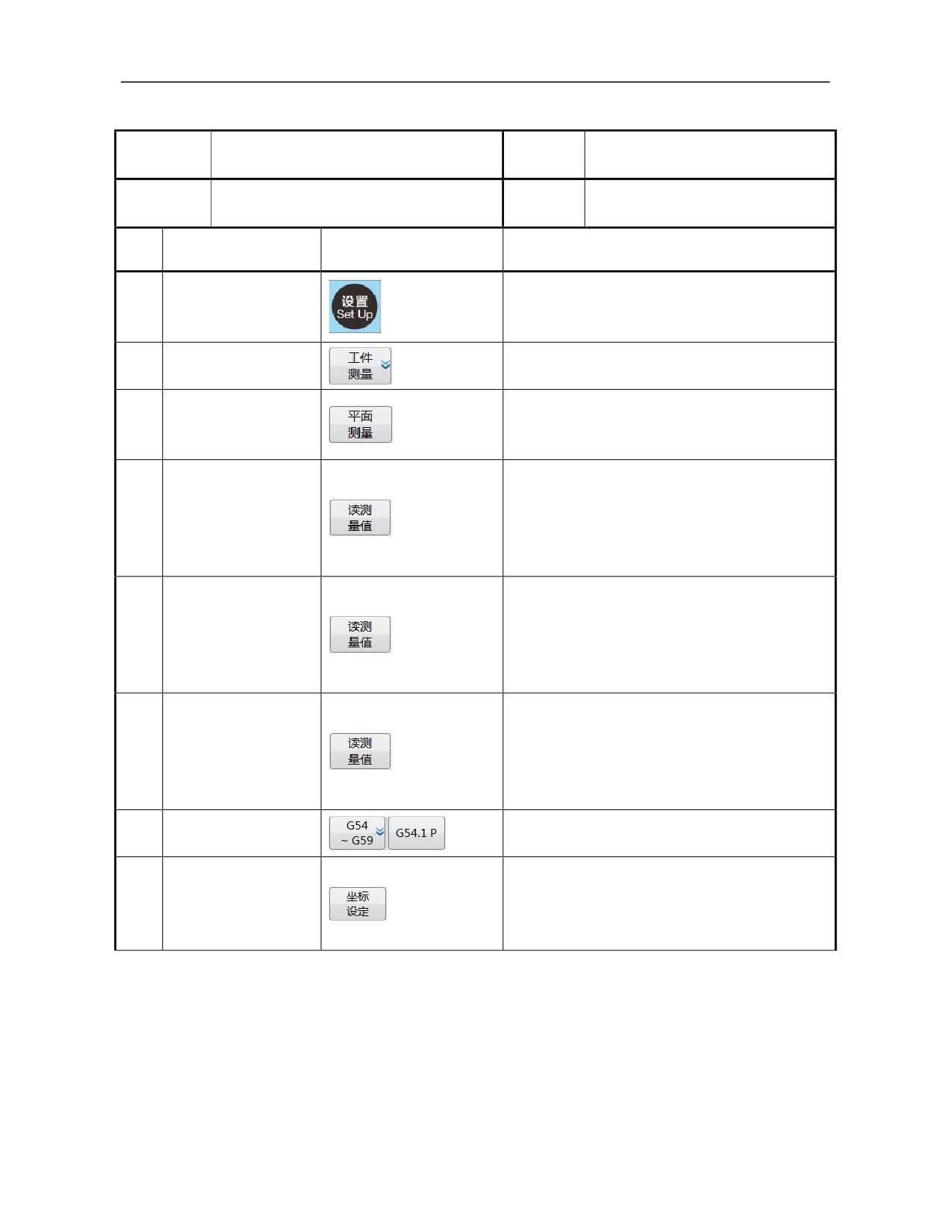
machining.
Operation
Working
Plane measurement
Jog, handwheel
name
mode
Basic
The system is allowed to run
under
jog
Display
See
Chapter
3
"Workpiece
requirements
mode and handwheel mode
interface
measurement" interface
SN
Operation steps
Key
Description
Enter the main interface of "Setup" function
1
Press 〖Setup〗
set
Press
『 Workpiece
Enter the default interface of "Workpiece
2
measurement』
measurement" function
Switch to the plane measurement function
Press
『 Plane
3
interface
measurement』
Input the cursor on X axis coordinates
Take
X axis
Move the tool to a point on the edge of X axis
4
coordinates
of
of the workpiece in handwheel mode, and
workpiece
acquire coordinates of X axis based on the
measured value
Input the cursor on Y axis coordinates
Take
Y axis
Move the tool to a point on the edge of Y axis
5
coordinates
of
of the workpiece in handwheel mode and
workpiece
acquire coordinates of Y axis based on the
measured value
Input the cursor on Z axis coordinates
Take
Z
axis
Move the tool to a point on the edge of Z axis
6
coordinates
of
of the workpiece in handwheel mode and
workpiece
acquire coordinates of Z axis based on the
measured value
Select
coordinate
Select the coordinate system to be set
7
system
The system calculates measurement results
Press
『 Coordinate
and assign them to the selected coordinate
8
setup』
system
8.2.3 Circle Center Measurement
This measurement mode determines the circle center through three points
and sets the circle center as the zero point of workpiece coordinate. (A, B
and C in the specification represent three points on the circle)
145
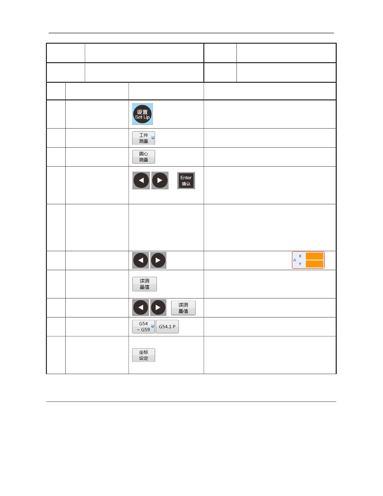
Operation
Working
Circle center measurement
Jog, handwheel
name
mode
Basic
The system is allowed to run under jog mode
Display
See
Chapter
3
"Workpiece
requirements
and handwheel mode
interface
measurement" interface
SN
Operation steps
Key
Description
Enter the main interface of "Setup" function
1
Press 〖Setup〗
set
Press
『 Workpiece
Enter the default interface of "Workpiece
2
measurement』
measurement" function
Press
『Circle center
Switch to the plane measurement function
3
measurement』
interface
Select and confirm arc plane using 「Cursor」
Select
coordinate
and 「Enter」;
4
plane
Display of coordinate axis of A, B and C
points changes with plane setup.
Move the tool to A point manually (the tool
touches the arc of workpiece);
Move the tool to A
5
--
A, B and C points can be any unrepeated
point of the circle
points on the arc and should be distributed
evenly.
Select A point setup display.
6
Press 「Cursor」
Press
『 Read
Read the machine coordinates when the tool
7
measurement 』 soft
is at A point.
key
Read coordinates of
8
Repeat steps 5, 6 and 7.
the points B and C
Select
coordinate
Select the coordinate system to be set.
9
system
The system calculates the measurement
Press
『 Coordinate
results and assign them to the selected
10
setup』
coordinate system.
8.3 Automatic Tool Setting
"Automatic tool setting" submenu under "Setup" function set can measure
tool length automatically. The "Auto tool setting" function includes single
tool single workpiece measurement mode, single tool multiple workpiece
measurement mode and multiple tools multiple workpiece measurement
mode. The function interface is shown below. In the multiple tools
146
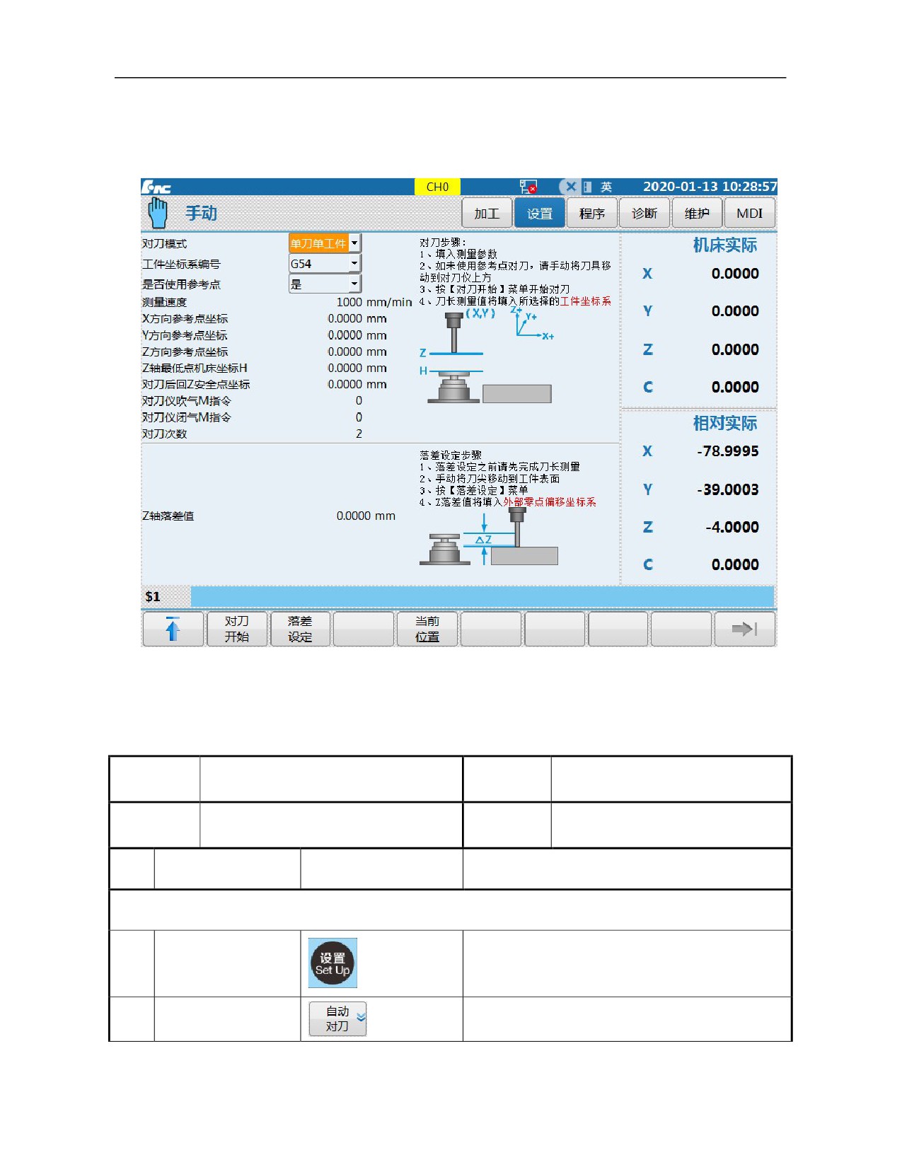
multiple workpiece measurement mode, the multiple tools can be
replaced automatically and the measured value of tool length can be
saved in the tool compensation interface.
8.3.1 Single Tool Single Workpiece Measurement
Operation
Working
Single tool single workpiece measurement
Jog, handwheel
name
mode
Basic
The machine tool is equipped with the
Display
"Auto tool setting" sub-interface
requirements
environment of tool setter test
interface
SN
Operation steps
Key
Description
I. Preparation for tool setting
Enter the default interface of "Setup" function
1
Press 〖Setup〗
set and level 1 menu.
Press
『 Auto tool
2
Enter the "Auto tool setting" function interface.
setting』
147
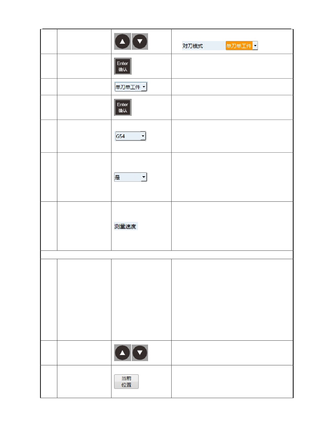
Move the cursor to "Tool setting mode".
3
Press 「Cursor」
4
Press 「Enter」
Activate "Tool setting mode" drop-down box.
Select "Single tool
5
Select "Single tool single workpiece".
single workpiece"
6
Press 「Enter」
Confirm the selection of "Tool setting mode".
Select
the
set
workpiece coordinates
Select
workpiece
corresponding to the tool;
7
coordinate system
Perform the selection and confirmation as per
the steps 3, 4, and 6 above.
When the position of tool setter has never been
set, select and use the reference point;
Select whether to use
If "No" is selected, the steps of tool setter
8
the reference point
presetting will be skipped;
Perform the selection and confirmation as per
the steps 3, 4, and 6 above.
Select suitable measurement speed according to
Z axis height of the reference point,
Input
measurement
When the tool touches the tool setter, it is set as
9
speed
F50 by default;
Perform the selection and confirmation as per
the steps 3, 4, and 6 above.
II. Presetting of initial position for tool setting
"Coordinates of reference point in X, Y and Z
directions" preset the initial position of tool
setting. During automatic tool setting, all tools
quickly reach this position from the safe point
Move the tool to the
Handwheel or
jog
axis
and then touch the tool setter at the
10
preset position of tool
movement key
measurement speed;
setter manually
On X and Y axes, try to make the tool in the
center of tool setter;
On Z axis, ensure all tools do not touch the tool
setter while reaching this position.
Move the cursor to "Reference point coordinates
11
Press 「Cursor」
in X direction"
The system sets X axis position of current tool
Press
『 Current
as the X axis position of the tool setter in the
12
position』
machine coordinate system;
Then, the positions of Y and Z axes remain
148
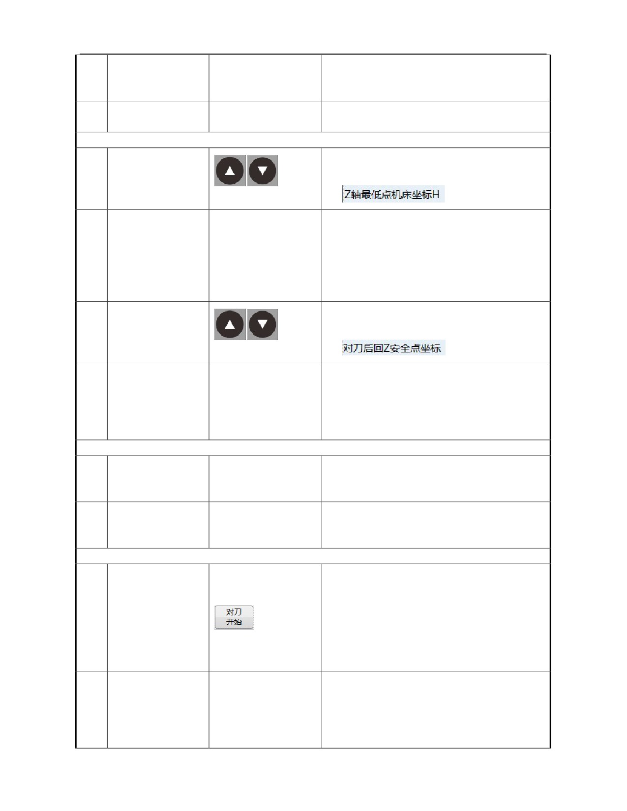
unchanged;
The value also can be set manually based on
steps 3, 4 and 6.
Repeat steps
11 and
Set reference point coordinates in Y and Z
13
--
12
directions respectively.
III. Safe position presetting
Move the cursor to "Machine tool coordinates H
of the lowest point on Z axis"
14
Press 「Cursor」
The lowest position of spindle, ensuring all tools
can touch the tool setter;
Input machine tool
The shortest tool can make the upper surface of
15
coordinates H of the
---
the tool setter be pressed down within
5mm
lowest point on Z axis
distance;
Input mode: "Jog" and "Current position".
Move the cursor to "Return to Z safe point after
tool setting".
16
Press 「Cursor」
This position is where the tool reaches rapidly
Input tool setting and
after tool changing;
17
return to coordinates
--
This position should ensure that all tools cannot
of Z safe point
touch the tool setter;
Input mode: "Jog" and "Current position".
IV. Auxiliary action presetting
Input the command
Set if the tool setter has blowing function;
18
for the tool setter to
otherwise, it is 0 by default.
blow and hold the air
Refer to the slow-speed tool setting times. The
Input tool setting
19
collision of the tool with the tool setter at the
times
first rapid drop is not counted.
V. Automatic tool setting and drop setup
Start tool setting;
After tool setting, save the measured value in the
workpiece coordinate system;
Press
『 Start tool
20
If an alarm is given in the process of
setting』
measurement, the measurement is stopped, and
the measurement is performed again after check
and debugging.
Move the tool nose to
"Drop setup" is to set the drop between the
the position where Z
upper surface of tool setter and zero position of
21
axis of the workpiece
--
Z axis of workpiece coordinate;
coordinate system is 0
This operation requires that the tool reaches Z0
in handwheel mode
of workpiece coordinate accurately;
149
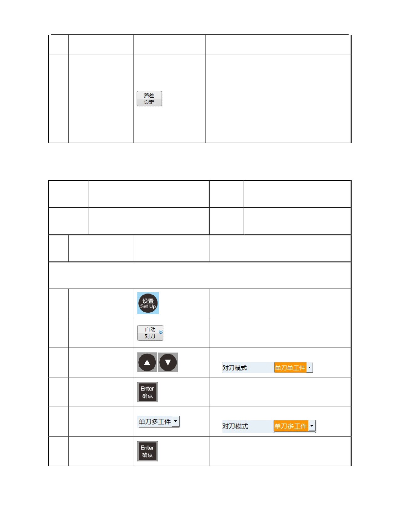
If the tool cannot reach Z0 of workpiece
coordinate, treat after "Drop setup".
Drop is set when no machine tool runs. After
calculation, drop of Z axis is set in the offset
coordinates of external zero point;
If the tool cannot reach the workpiece
22
Press 『Drop setup』
coordinates Z0 position, but coordinates of the
tool on Z axis in the workpiece coordinate
system can be accurately identified
(such as
"a"), input "-a" in incremental mode based on
the external zero offset set.
8.3.2 Single Tool Multiple Workpiece Measurement
Operation
Single
tool
multiple
workpiece
Working
Jog, handwheel
name
measurement
mode
Basic
The machine tool is equipped with the
Display
"Automatic tool setting" sub-interface
requirements
environment of tool setter test
interface
SN
Operation steps
Key
Description
I. Preparation for tool setting
Enter the default interface of "Setup" function
1
Press 〖Setup〗
set and level 1 menu.
Enter the "Auto tool setting" function
Press
『 Auto tool
2
interface.
setting』
Move the cursor to "Tool setting mode" column.
3
Press 「Cursor」
4
Press 「Enter」
Activate "Tool setting mode" drop-down box.
Select "Single tool multiple workpiece".
Select "Single tool
5
multiple workpiece"
6
Press 「Enter」
Confirm selection of "Tool setting mode".
150