HNC-8 System Operating. Manual (Milling Machine) V2.4 Series - page 4
Note:
Parameter setup and modification are limited, input a password of
corresponding permission while setting and modifying parameters.
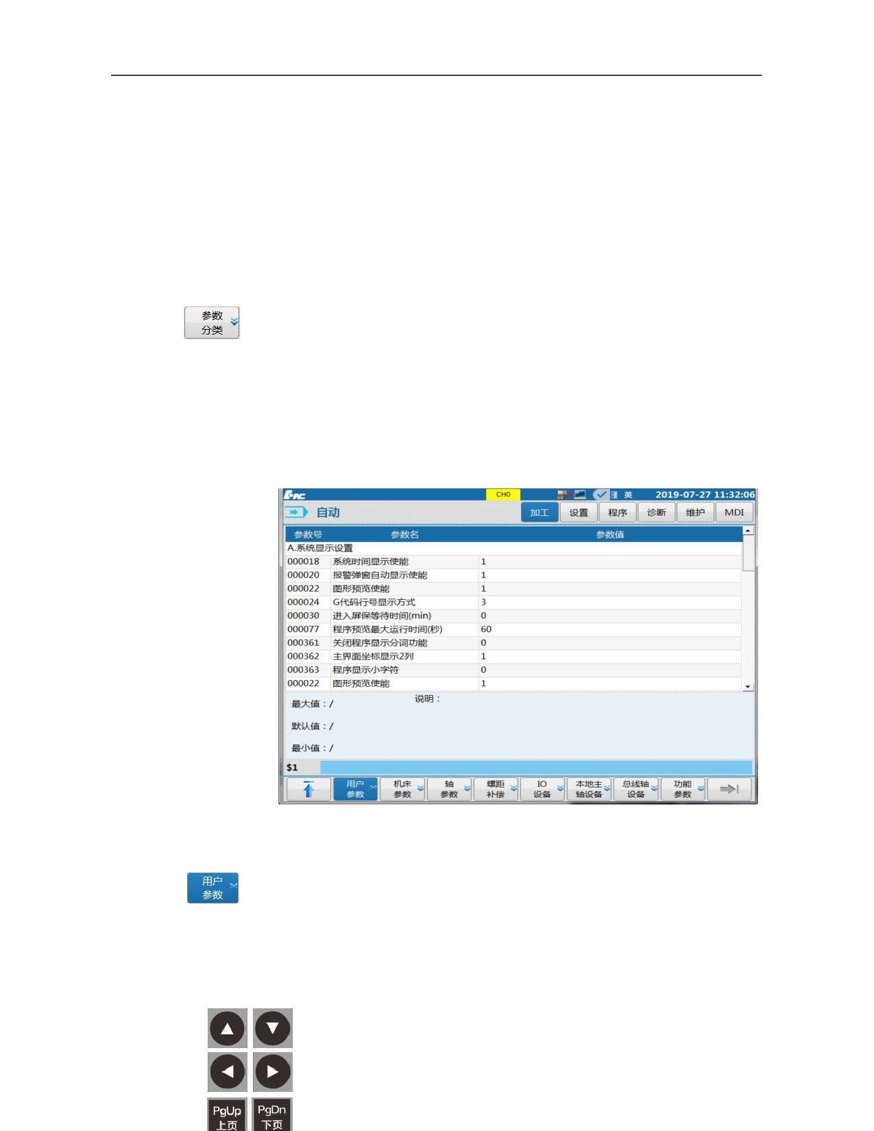
3.6.4 "Parameter Classification" Sub-interface
The "Parameter classification" sub-interface can be used to set device
interface parameters such as axis, MCP and IO as well as user parameter,
machine parameter and machining parameter. Pitch compensation function is
also under this function set.
Generally, parameter values can be inputted by keys on the panel or backed
up and imported. This section introduces direct input by panel keys only. For
parameter backup and import, refer to 9 Machine tool commissioning.
All soft key functions under the "Parameter configuration" sub-interface are
limited functions, and password should be entered to enable them.
3.6.4.1 Direct input of parameter classification value
Press 『User parameter』, 『Machine parameter』 and 『Axis
parameter』 soft keys to enter different sub-interfaces;
Press 『Enter password』 to activate the input box;
Enter user password, such as the machine tool manufacturer
permission password "HOD";
Press 「Enter」 to confirm the input;
76

Press 「Cursor」 or 「PgUp/PgDn」 to select the value on the
right of parameter name;\
Press 「Enter」 to activate the value input status;
Input the value to be set such as “1”;
Press 「 Enter」 to confirm, and a prompt message "Setup
succeeds, save to take effect" will be given;
Press 『 Save』 soft key and a prompt message "Save the
modification or not" will be given;
Press 「Y」, a prompt message "Save successfully" will be given
and parameters will be validated immediately.
3.6.4.2 Direct input of pitch error compensation value
Press
「 Pitch compensation 」 soft key to enter the
"Compensation information" sub-interface;
Select compensation type, such as "Unidirectional
compensation";
Press 「Cursor」 to move the cursor to the value setup area of
"Starting
point",
"Compensation interval", "Backlash
compensation type", "Compensation points", "Initial number of
data table" and "Backlash value";
Press 「Enter」 to activate the value input status;
Input the corresponding value in the input box (initial number of
data table is often 71000)
Press 「Enter」 to confirm the input;
Press 『Save』 soft key and a prompt message "Parameters have
been saved" will be given.
3.6.5
Classification and Switching of Management Permission
In response to the different application requirements of CNC machine tools, the
system has 5 types of operating permissions, which are operator, workshop
administrator, machine tool manufacturer, CNC manufacturer and system
administrator. Management functions of various permissions are roughly as
follows:
"System administrator": Development, test and customer service with system
software maintenance permission.
77

"CNC manufacturer": Product manufacturing and quality inspection. It has
permissions of system upgrade, system parameter setup, PLC program editing and
limited-time shutdown setup. Permission login password is HIG.
"Machine tool manufacturer": Machine tool commissioning. It has permissions of
partial system parameter modification, error compensation data entry and
shutdown timer setting. Permission login password is HOD.
"Workshop administrator": Machining commissioning. It has permissions of
partial user parameter modification, editing parts program and editing tool
compensation data. Permission login password is GOD.
"Operator": Machining operation. It has permissions of editing tool compensation
data and selecting program. There is no password need for this permission.
Permission type
System
System
Machine tool
Workshop
Operator
Operation function
administrator
manufacturer
manufacturer
administrator
User parameter
Yes
Yes
Yes
No
No
Machine parameter
Yes
Yes
Yes
No
No
Axis parameter
Yes
Yes
Yes
No
No
Pitch error
Parameter
Yes
Yes
Yes
No
No
compensation
Classification
I/O device
Yes
Yes
No
No
No
Local spindle device
Yes
Yes
No
No
No
Bus axis device
Yes
Yes
No
No
No
Function parameter
Yes
Yes
Yes
No
No
System upgrade
Yes
Yes
No
No
No
Permission management
Yes
Yes
Yes
Yes
Yes
Batch commissioning
Yes
Yes
Yes
No
No
User setup (except display setup)
Yes
Yes
Yes
Yes
No
Data management
Yes
Yes
Yes
Yes
No
Spatial compensation
Yes
Yes
Yes
No
No
Time setup
Yes
Yes
Yes
No
No
Process package
Yes
Yes
Yes
No
No
Register
Yes
Yes
Yes
No
No
Alarm history
Yes
Yes
Yes
Yes
No
Ladder monitoring
Yes
Yes
Yes
Yes
No
Ladder
Ladder editing
Yes
Yes
Yes
No
No
diagram
Ladder information
Yes
Yes
Yes
No
No
Signal tracking
Yes
Yes
Yes
No
No
Status display
Yes
Yes
Yes
Yes
No
78

Macro-variable
Yes
Yes
Yes
Yes
No
User macro
Yes
Yes
Yes
Yes
No
Servo adjustment
Yes
Yes
Yes
No
No
Clear log
Yes
No
No
No
No
Select program, find,
Yes
Yes
Yes
Yes
No
sort
Verify, any line
Yes
Yes
Yes
Yes
Yes
Relative clear
Yes
Yes
Yes
Yes
Yes
Display mode, path
Yes
Yes
Yes
Yes
Yes
switching
Program
Machining statistics
Yes
Yes
Yes
Yes
Yes
function set
Machining
Yes
Yes
Yes
Yes
No
optimization
Program editing
Yes
Yes
Yes
Yes
No
Read only, writable
Yes
Yes
Yes
Yes
No
attribute setup
User macro
Yes
Yes
Yes
Yes
No
Tool compensation
Yes
Yes
Yes
Yes
Yes
Coordinate system
Yes
Yes
Yes
Yes
Yes
Workpiece
Yes
Yes
Yes
Yes
Yes
Setup
measurement
function set
Magazine, tool life
Yes
Yes
Yes
Yes
No
setup
Broken tool detection
Yes
Yes
Yes
Yes
No
Automatic tool setting
Yes
Yes
Yes
Yes
No
Parameter
Yes
Yes
Yes
No
No
configuration
User macro
Yes
Yes
Yes
Yes
No
Machining
Edit program
Yes
Yes
Yes
Yes
No
function set
Select program (except
Yes
Yes
Yes
Yes
No
"System disk")
Other operations
Yes
Yes
Yes
Yes
No
This system can set the permission of "Operator" or "Workshop administrator" as
the default permission through parameter 000359 in NC parameter table, and
other permissions can be switched through entering a password after startup.
Permission switching is shown as below:
Press 〖Maintain〗 function key to enter the default interface of the
"Maintain" function set
Press 〖Permission manage〗 soft key to enter the "Permission manage"
79
sub-interface
Press 〖Logout〗 soft key to exit the current permission;
Press 〖Left and right cursors〗 to select the required permission;
Press 〖Login〗 soft key to activate the input box, and a prompt message
"Please enter a login password" will be given;
If the machine tool manufacturer permission is selected, please enter:
“HOD”;
Press 「Enter」 to confirm the input. Then permission is modified
successfully.
3.6.6 System Upgrade
"System upgrade" function is available for the system manufacturer only. Thus,
users should set the permission under the "Maintain" function set after startup
(The permission is not saved after shutdown).
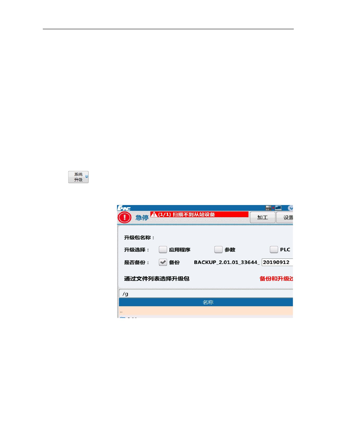
After permission setup, press 『System upgrade』 soft key under "Maintain"
function set to enter the "System upgrade" sub-interface (as shown below).
Press 『Window switch』 soft key to select the "Upgrade selection"
window on the upper part of the interface
Press 「Left and right cursors」 to select the required items; (BTF is to
upgrade all items)
Press 「Enter」 to confirm;
For backup, select "Backup" (the default backup target disk is the user
disk);
Press 『Window switch』 soft key to select the upgrade package file
80
source selection window on the lower part of the interface (the default
upgrade source disk is the USB flash disk);
Press 「Up and down cursors」 to select the upgrade package file (the
upgrade package file name must be suffixed with . BTF);
Press 「Enter」 to confirm and start the upgrade
Note:
Upgrade can be conducted with system permission by HNC CNC
technical personnel .
System upgrade must be conducted under "Emergency stop" status
Upgrade patch file must be .BTF file and file name is suffixed
with .BTF
The default backup disk is the user disk, pay attention to the size of
user disk during backup
3.6.7
Data Management
In the data management interface, single file of parameters, PLC, canned
cycle, log, compensation, oscilloscope can be loaded/backed. This section
takes the example of loading/backing up system parameter files. The
operation steps of loading and backing up other files (except the error
compensation file) are the same.
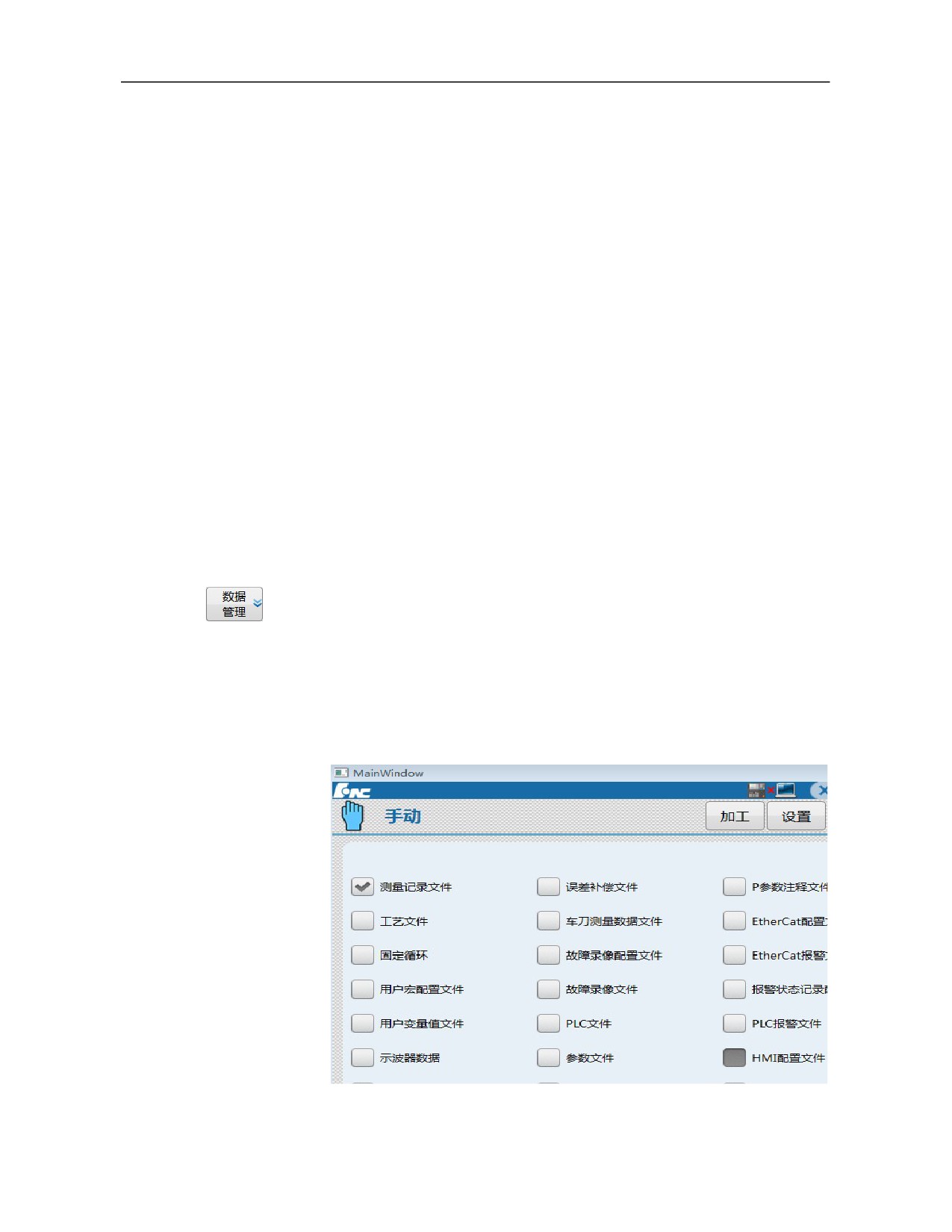
Press
『Data management』 soft key under the main menu of the
"Maintain" function set to enter the data management sub-interface (as
shown below).
81
Press 「Cursor」 to select the type of data to be loaded or backed up;
Press 「Enter」 to confirm the selection;
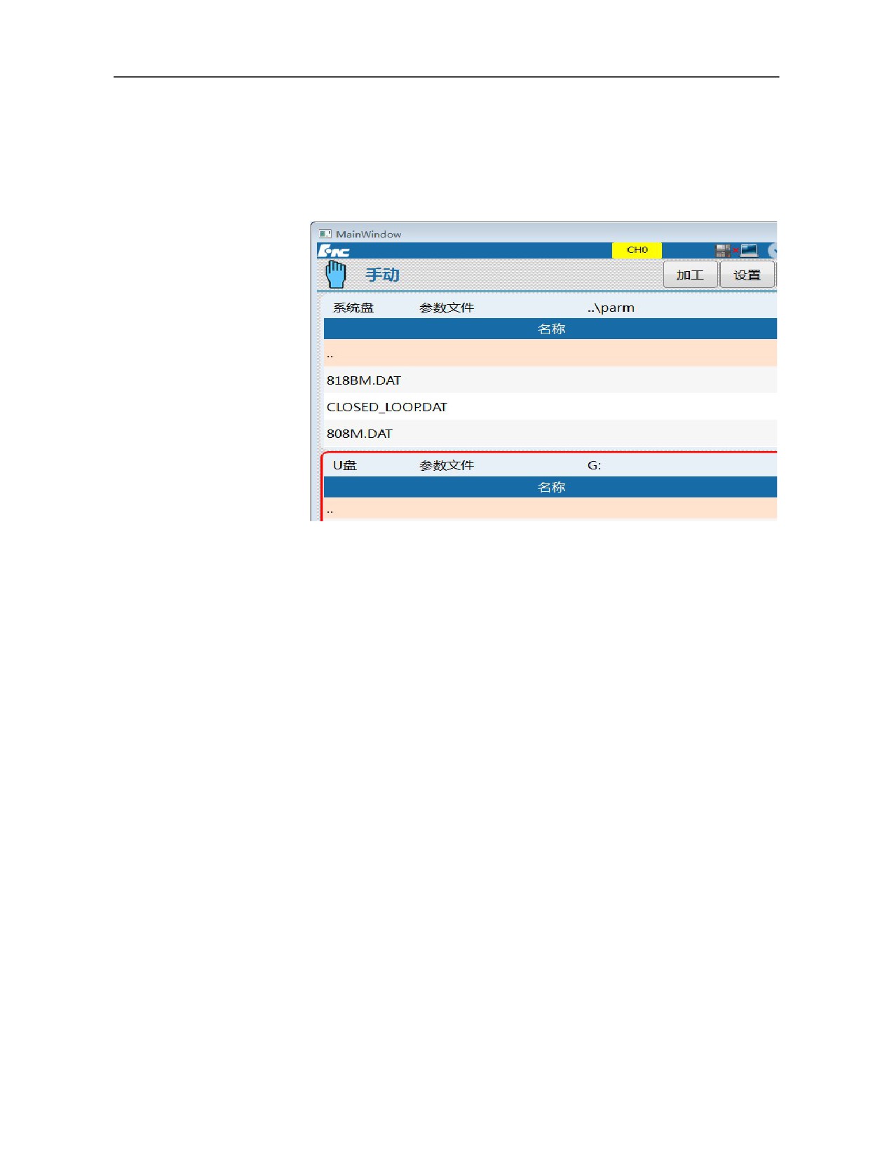
Press 『USB flash disk』 or 『User disk』 and select 『Load』 or
『Backup』 to enter the load or backup sub-interface (as shown
below)
To load data in USB flash disk or user disk to system disk, press
『Window switch』 soft key to move the red box to USB flash disk or
user disk on the lower part of the above figure;
Press 「Enter」 to open the file directory and press 「Cursor」 to
select the data file to be loaded;
Press 『Load』 soft key, and the input box gives a prompt message
"Whether to load the selected file?"
Press 「Y」 to load the data file;
Press 「N」 or 「Reset」 to abandon loading data file.
To back up data in system disk in USB flash disk or user disk, press
『Window switch』 soft key to move the red box to the system disk
above the above figure;
Press 「Enter」 to open the file directory and press 「Cursor」 to
select the data file to be backed up;
Press 『Backup』 soft key and the input box gives a prompt
message "Whether to back up the selected file?"
Press 「Y」 to back up data file;
Press 「N」 or 「Reset」 to abandon backing up data file.
Note Power failure is not allowed during backup or loading.
82
3.6.8 User Setup
User setup is used for control switches of some common display and PLC
so that users can set different functions based on different needs.
Press 『User setup』 soft key under the main menu of the "Maintain"
function set to enter the "User setup" submenu (as shown below).
3.6.8.1 Display setup
As mentioned in the introduction of the processing interface, the soft key
"Display Switching" under the "Processing" function set can switch
between "Large-character coordinates + program", "joint coordinates",
"graphics
+ program", and "program". "Big character coordinate
+
program" and "Joint coordinate" interfaces can be set here.
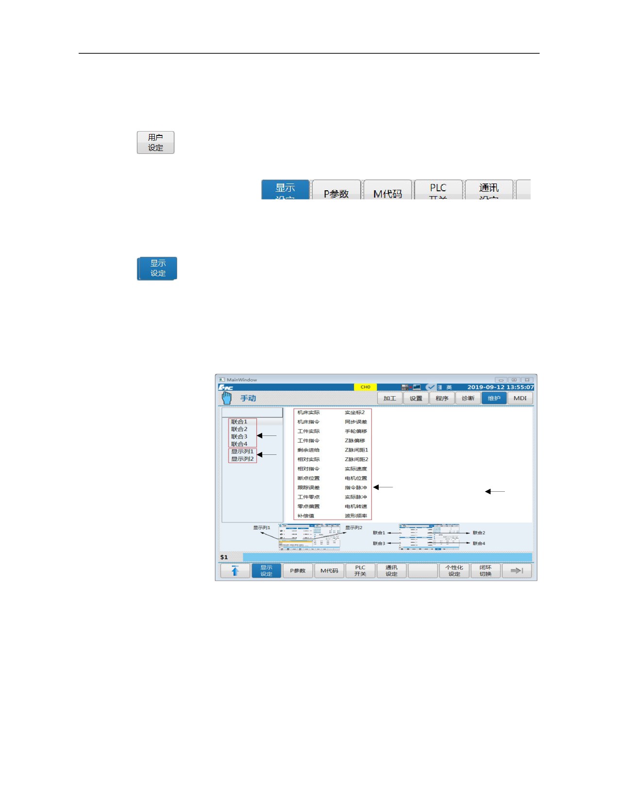
Press『User setup』soft key under the "User setup" sub-interface to enter
the "Display setup" submenu (as shown below).
Left
column 1
Left
column 2
Right
Right
column 1
column 2
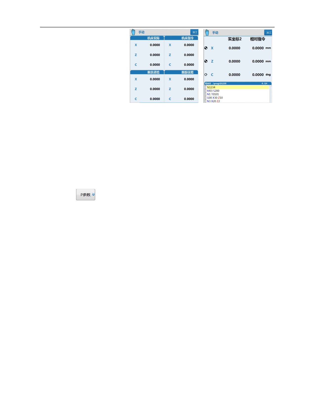
When the cursor moves to the left column 1 in the above figure (joint
coordinates 1-4), the content of the right column 1 is displayed on the
right of the above figure, and the display content in the "Joint coordinate"
interface can be selected from the right column 1 (as shown in the below
left figure).
83
Joint coordinate display
Big character coordinate + program display
When the cursor moves to the left column 2 in the above figure (display
columns 1-2), the content of the right column 2 is displayed on the right
of the above figure and the display content in the "Big character
coordinate + program" interface can be selected from the right column 2
(as shown in the above right figure)
3.6.8.2 Set "P parameter"
P parameter is a parameter relating to machining and system operation.
All PLC subprogram switches and PLC determinations of system are set
by P parameter, and P parameter can be set under the "User setup"
interface. Whereas this parameter has a great effect on safety of machine
tool, please be sure to modify it under the guidance of related authorized
person.
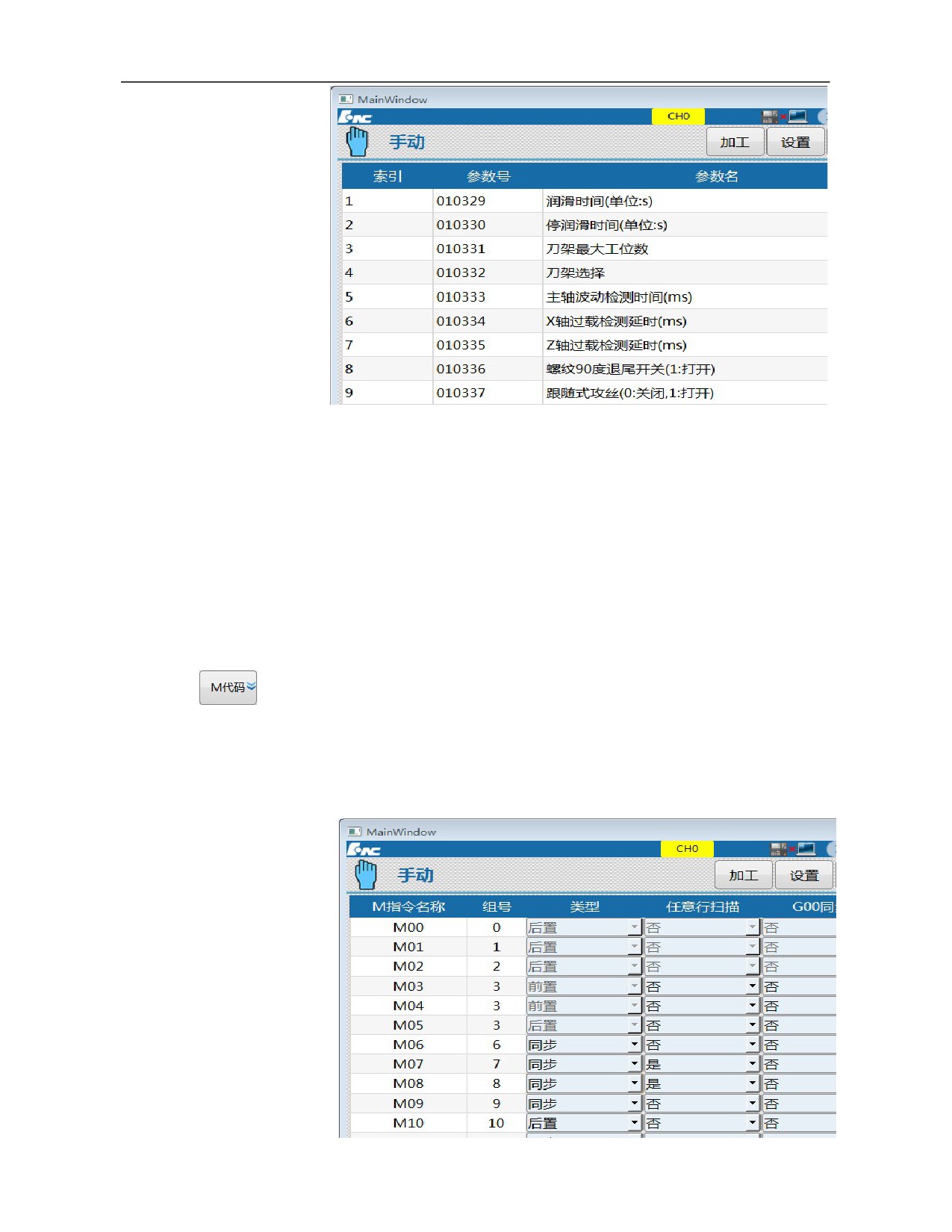
P parameter corresponds to the parameters after machine tool user
parameter 010300 and correspond to the same memory address with these
user parameters. 『P parameter』 soft key is a shortcut key.
Press 『P parameter』 soft key under the "User setup" sub-interface to
enter the "P parameter" sub-interface (as shown below).
84
It should be noted that when a function is enabled through setting P
parameter, not only should PLC switch be set, but also other relevant
parameters and functions should be set. e.g.: When rotation function of
mill spindle is enabled, not only should parameters of spindle rotation
ON/OFF be set, but also spindle rotation parameters should be set;
otherwise, the spindle cannot rotate.
3.6.8.3 Set "M code"
M code table is mainly used to set the determinations such as M code
validation, validation sequence when M codes and G00 are in the same line and
whether M codes are identified in any line scanning.
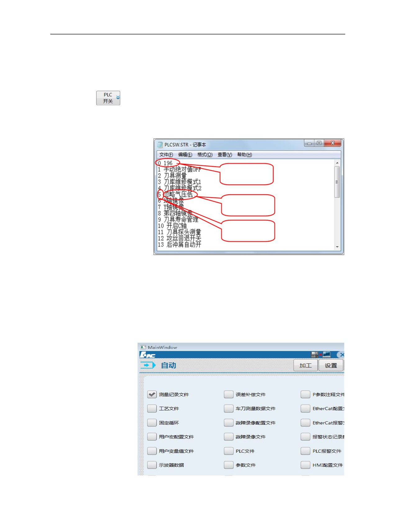
Press 『M code』 soft key under the "User set" sub-interface to enter the "M
code" submenu (as shown below).
85
Under the "M code" sub-interface, M codes have four setups: type (pre or
post), whether any line is scanned, G00 synchronization, and spindle
control. Where, setup of M00, M01, M02, M05, M30, M92 and M93 codes
is cured of the system, of which the Pre/Post attribute cannot be changed.
M00: Program suspension
While executing M00 command, the execution of current program is
suspended, and the system is at feed hold state, so that the operator can
conducts the operations including size measurement of tool and workpiece,
workpiece turn-around and manual speed change. Press [Cycle start] to
continue to run the program;
M01: Optional stop
If this function key on the system panel lights up, the system suspends the
execution of current program while executing M01 command, and at time
tim the system is at feed hold state; so that the operator can conducts the
operations including size measurement of tool and workpiece, workpiece
turn-around and manual speed change. Press [Cycle start] to continue to
run the program;
If the “Optional stop” key on the system panel does not light up, the system
does not suspend the execution of current program while executing M01
command.
M92: Program suspension (wait for user's manual intervention)
While executing M92 command, the system suspends the execution of
current program and waits for user's manual intervention before cycle start.
The difference from M00 is that the user can manually intervene with axes,
and move axes under "Jog" mode. Then, press "Cycle start" under "Auto "
mode to continue running the current program.
Note: When M92 is used, The channel parameter 040059【Automatic
breakpoint block number return】 must be set as 0, that is, the function of
returning to the breakpoint position automatically after manual intervention
is turned off. Otherwise, manual intervention is invalid.
M93: Program suspension (manual intervention is not allowed)
M93 command is equal to M00 command. Differnet from M92, user's
manual intervention is not allowed when M93 suspends the program.
M02: Program end
M02 is often edited in the last block of the main program. When the system
executes M02 code, spindle, feed and cooling of the machine tool stop, and
the machining is completed.
After a program using M02 ends, to re-execute the program, users should
recall and load the program and press [Cycle start].
86
M30: Program termination
M30 is often edited in the last block of the main program. When the system
executes M30 code, spindle, feed and cooling of the machine tool stop and
the machining is terminated, and then the system returns to program header
automatically.
After a program using M30 ends, to re-execute the program, recall and load
the program and press [Cycle start].
a) Pre or post
Pre: M code takes effect first when M code and G code are in the same
line;
Post: G code takes effect first when M code and G code are in the same
line;
Synchronization: M code and G code are executed simultaneously when
they are in the same line.
The synchronous execution of M code and G00 rapid traverse positioning
command is not included in the above three situations.
b) Scanning of any line
Yes: After the scanning mode of the channel parameter 040113 【Any line
mode selection】 is turned on, the system scans the M code while using any
line function.
No: While using any line function, the system does not scan the M code
whether any line function is turned on or not.
c) G00 synchronization
Yes: M code and G00 code are executed simultaneously;
No: M code and G00 code cannot be executed synchronously.
In HCNC system, the synchronous execution of M code and G00 is used as
a configurable attribute. If the system do not conduct cutting while
executing G00 command, some designated M codes can be executed
synchronously to improve efficiency, such as M03 spindle CW rotation,
M04 spindle CCW rotation, and M08 cooling ON, etc. After M code is
executed, the response conditions of M codes in PLC must trigger
G2562.13 signal and notify the system of executing the next block of
movement.
0
d) Spindle control
When M code is used to control CW rotation, CCW rotation and stop of
spindle, it can be marked and prompted using this configuration, and it has
87
no effect on the actual attribute and action of M code. It is often used for
marking M code of multiple channels and multiple spindles.
3.6.8.4 Set "PLC switch"
PLC switch setup function is to decompose the designated user P parameter
to
32 bits and every bit is a configurable PLC switch. PLC switch is
configured by PLCSW.STR configuration file under parm directory. The
file format is shown below:
User parameter number
cannot be modified.
Bit name, can be empty.
Bit index, starts from 1. The
lowest bit is 1 and the highest
bit is
32, may not be
continuous.
Note: Machine tool user parameter P196 of HNC-8 system is used as the PLC
switch file by default. The setting is closely related to PLC function and
cannot be modified without the guidance of CNC system commissioning
personnel.
After PLCSW.STR file is made, select “PLC switch file” to import PLCSW.STR
file into the system through "Data management". As shown below.
88
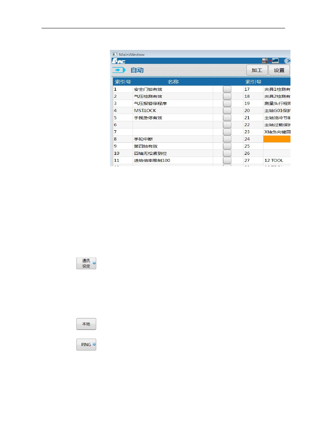
Press “Maintain→ User setup→ PLC switch” menu to enter the PLC switch
function interface and operate the designated P parameter by bit, as shown below:
Effective setup: Protect “ON” and “OFF” menus which can be operated only
through pressing "Effective setup" menu;
ON: Set bit of focus as ON;
OFF: Set bit of focus as OFF;
Setup result is saved in the designated user P parameter.
3.6.8.5
Communication setup
This function can realize communication between the upper computer of
the CNC system and the computer and the communication of shared disk of
regional machine tools.
Note: Network can be connected only after NC parameter 000050
【Whether to enable network】 is enabled
a) Communication between the upper computer of the CNC system and the computer
For communication between the upper computer of the CNC system and
the computer, ip of the computer and ip of the CNC system should be set in
the same block,
ip of the CNC system is 192.168.1.113 by default. ipv4 of the computer is
set to 192.168.1.XXX at the time of connection, and default gateway and
subnet mask of the computer are consistent with those of the CNC system.
Specific steps:
Press『Communication set』soft key under "Maintain" function set to
enter the sub-interface;
89
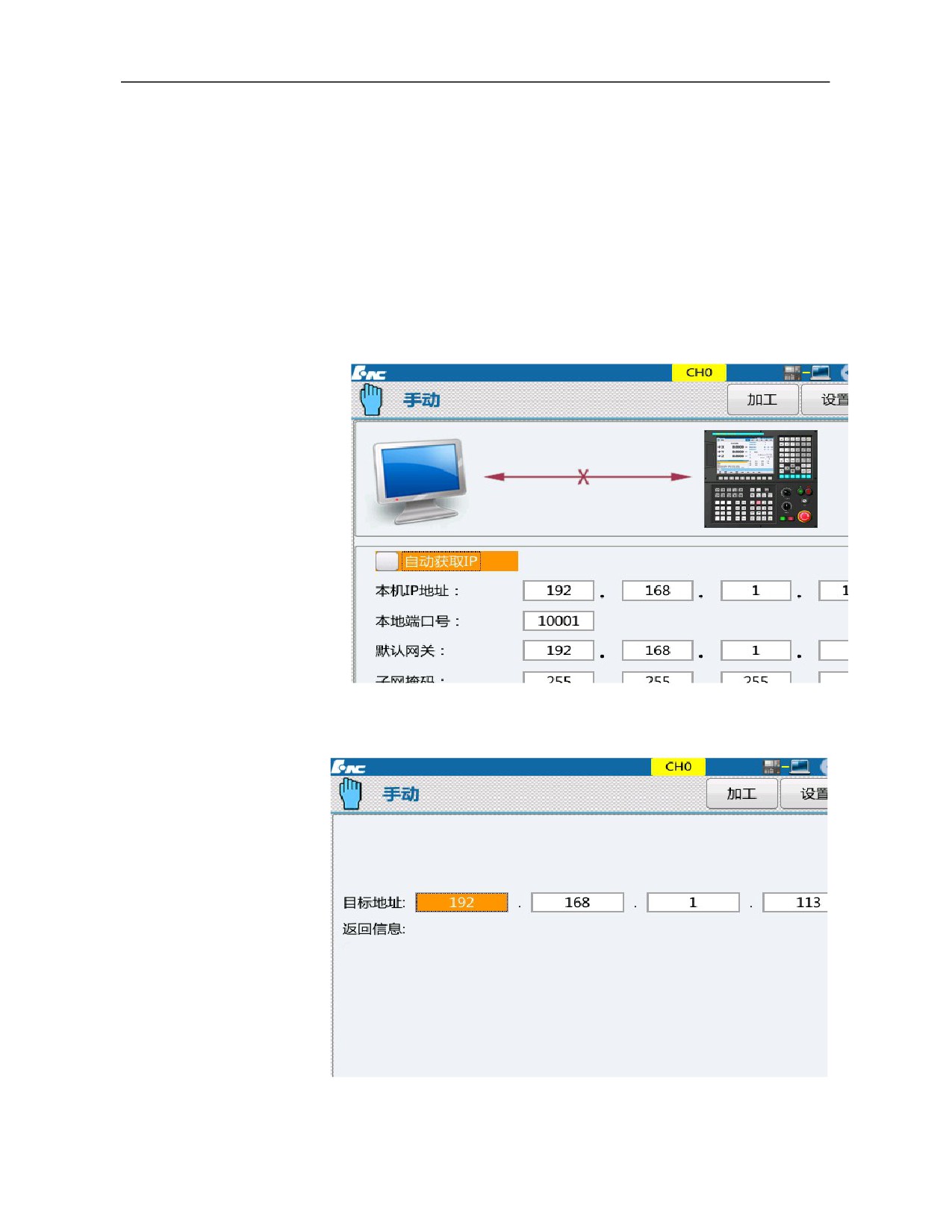
Press 『Local』 soft key to enter the "Local" connection sub-interface
(as shown below);
Move the cursor to where "Server IP address" is set, and set the
default IP address of the system, namely 192.168.1.113.
Move the cursor to "Local port number", "Default gateway" and
"Subnet mask" of the system and set them as the "Local port number",
"Default gateway" and "Subnet mask" of the computer.
Connect Internet access of computer and that of system IPC using
network cable. Pay attention not to connect to M3 or ETH port of
system IPC.
Users can PING system on computer or PING computer on system.
The PING interface of this system is shown in the figure.
While PING computer in the system, fill ip address of the computer
90
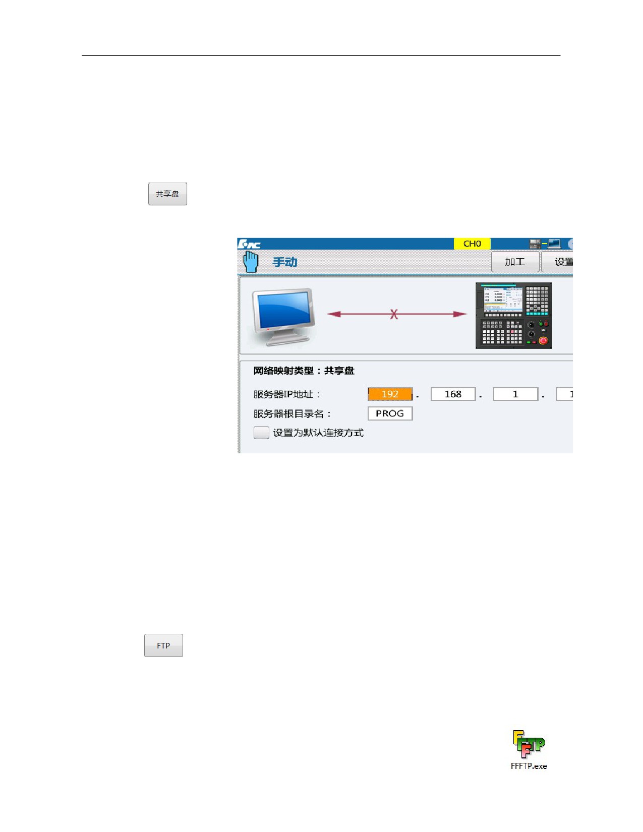
in PING interface and click on 『PING start』 soft key;
To terminate PING, press 「Reset」.
Note: Network cable must be connected well and Internet access must be
selected correctly.
b) Shared disk communication
If all machine tools in the machine tool factory are networked, all machine
tools can share codes and various configuration files in the shared disk.
When the machine tools are connected to the shared disk, open the shared
disk interface, as shown below:
Press『Communication setup』soft key under "Maintain" function set
to enter the sub-interface;
Press 『Shared disk』 soft key to enter the "Shared disk" connection
sub-interface (as shown above);
Move the cursor to where "Local IP address" is set and fill IP address
of shared disk of machine tool manufacturer.
c) FTP
FTP is a kind of connection software used to copy data from the computer
to the system or from the system to the computer.
Before FTP is used, ensure smooth network according to the previous
section.
Then, install the software FFFTP on computer (download
from the official website of HCNC, see the right icon)
91
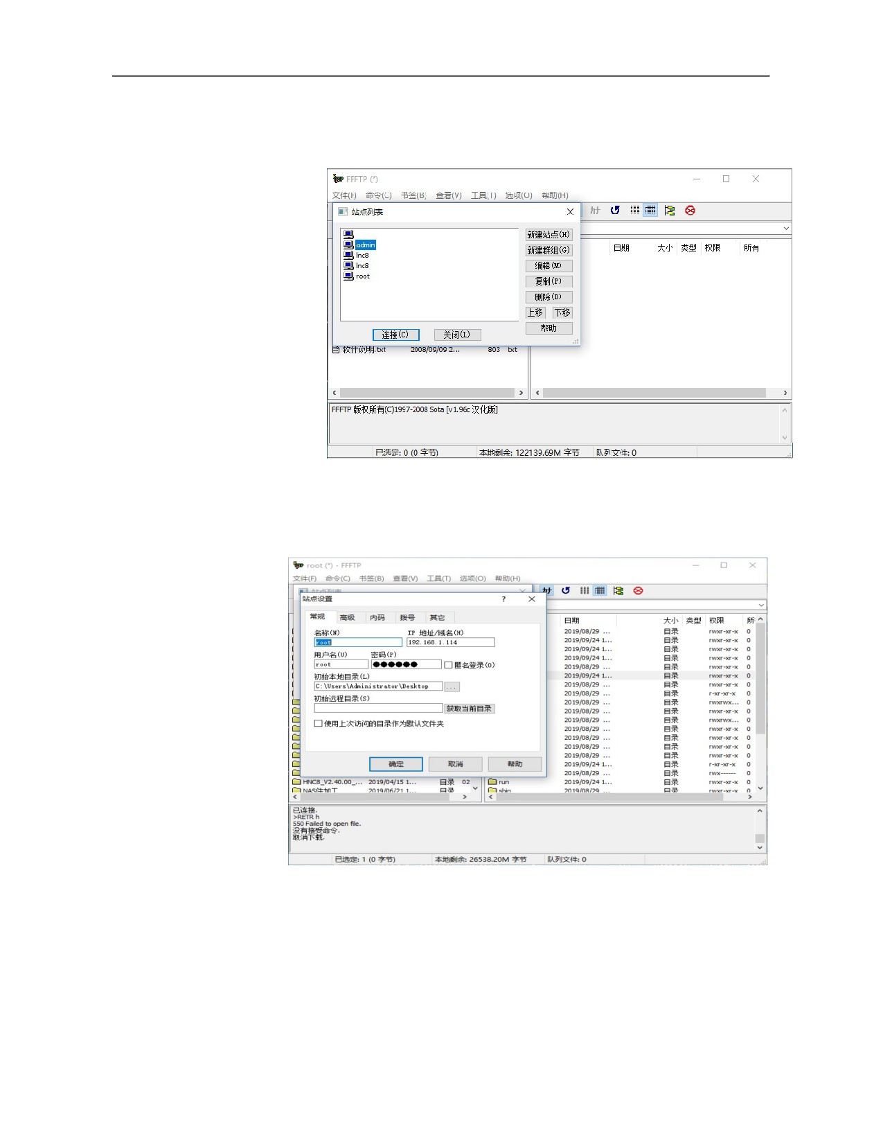
After ping the system and the computer, click on FFFTP icon and the
interface is displayed as below:
Users can select root login from the above interface station list. If there is
no required station, build a new station (such as root) and the station
setup interface is shown below:
ip address is set as the ip of the system;
Select and set the user name (such as root);
Login password is set as 111111;
Click on Enter to log in to the system and the login interface is
shown below.
92
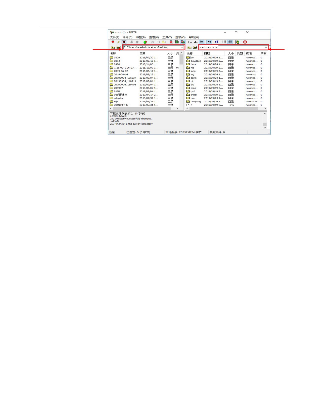
Area 1
Area 2
The transmission path of the system can be set in the above interface area
2 and system is often written in /h/lnc8/prog. The computer path can be
set in area 1.
After a path is designated, drag the file using mouse and transmit files
between the system and the computer.
Note: If ffftp cannot be connected, check the following setups
1.
Whether the network parameter 00050 enables the network, and
whether it is opened
2.
Whether the computer and the system are connected can be pinged
3.
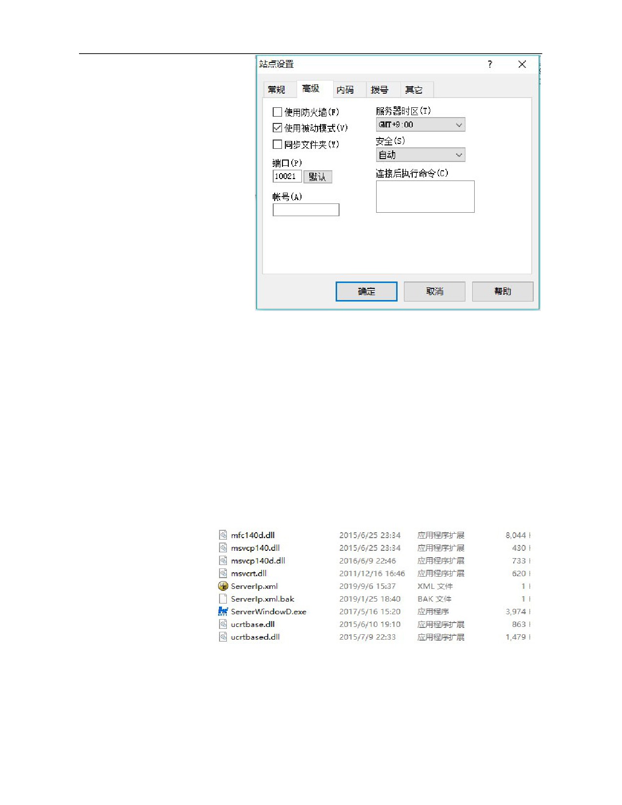
Whether port number is correct, including port number 10001 in the
CNC system interface and port number under the advanced menu of
ffftp.
93
d) plc online commissioning
Online commissioning of PLC refers to monitoring and modifying PLC
of system on computer. If it is inconvenient to modify and commission
PLC on system, this function can be used. The following conditions must
be met in use
The system and the computer must be connected, as shown in the
second section.
A suitable adapter is needed,
Setup steps for HCNC controller adapter software are as follows (it
should be noted that 1.26 and 2.XX series adapters are different).
(1) Turn on the adapter and find ServerWindowD.exe and Serverlp.xml
(2) Open Serverlp.xml and replace LocalIP to IP of this computer, which is
192.168.1.115 in this example. The port number must be consistent with that on the
system and should be edited and saved.
94
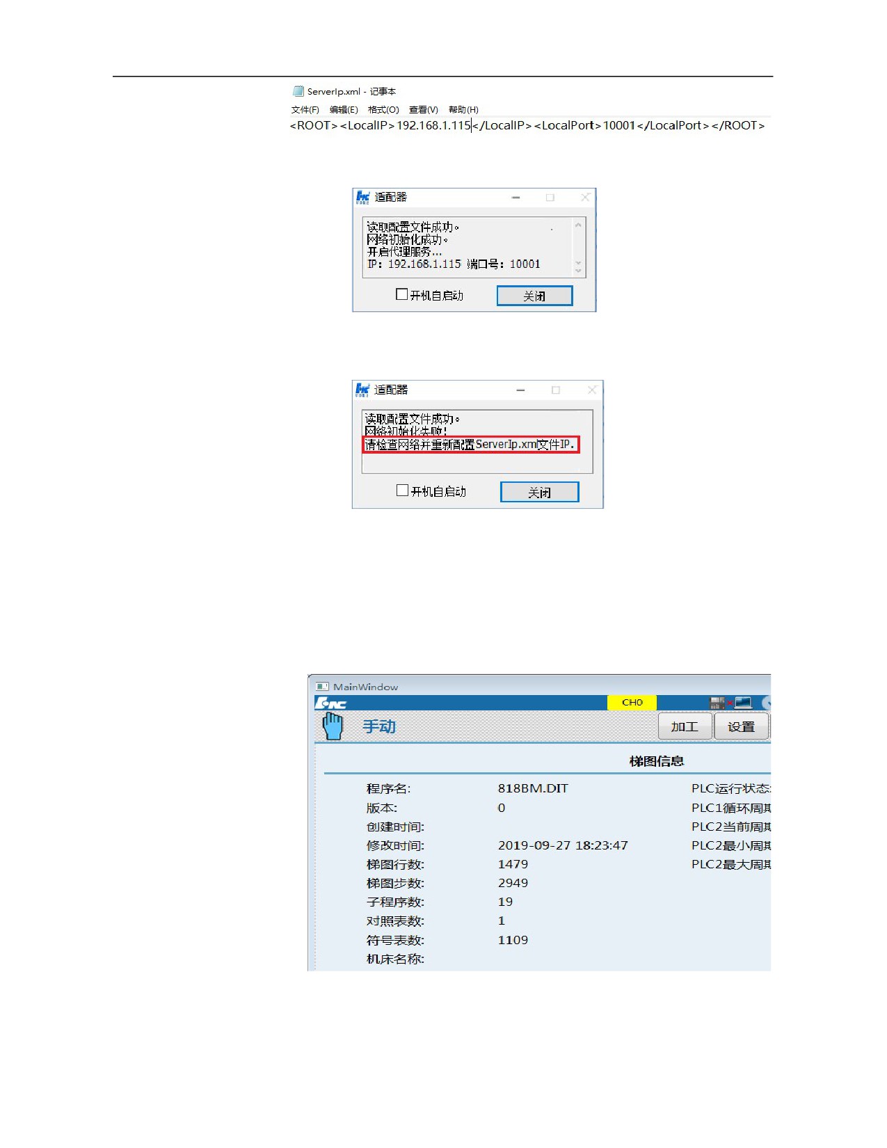
(3) Open ServerWindowD.exe, and the normal effect is shown below
If Serverlp.xml is not modified, an alarm will be given as shown in the
following figure
(4) Find the online commissioning in the second page of ladder diagram----ladder
diagram information menu under the diagnosis interface and click on it, the system
will give a prompt message that PLC is being commissioned online.
(5) Open the ladder diagram editing tools of 2.0, and click Network connection under
setup
95
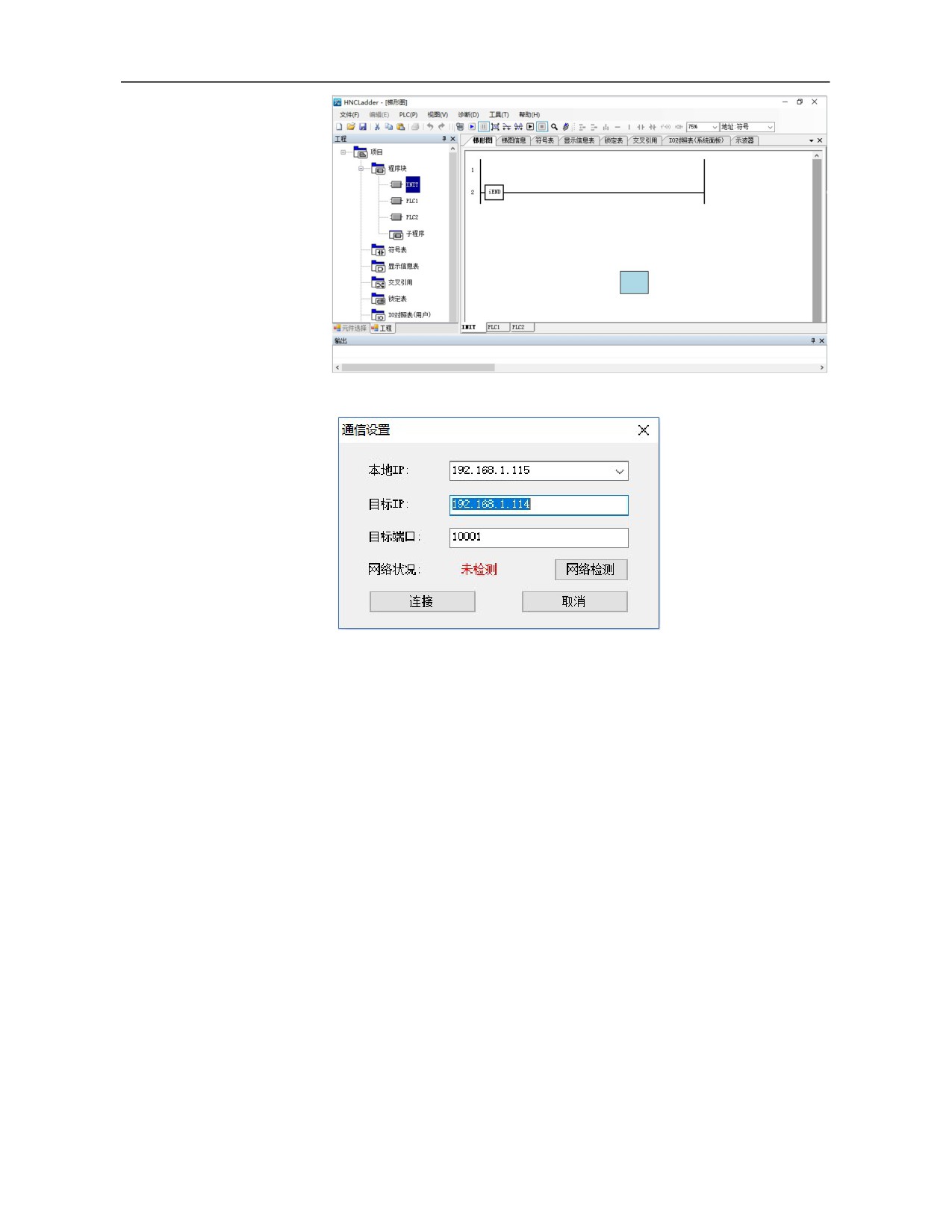
Correctly fill in IP of the computer and IP of the system and click to connect
96
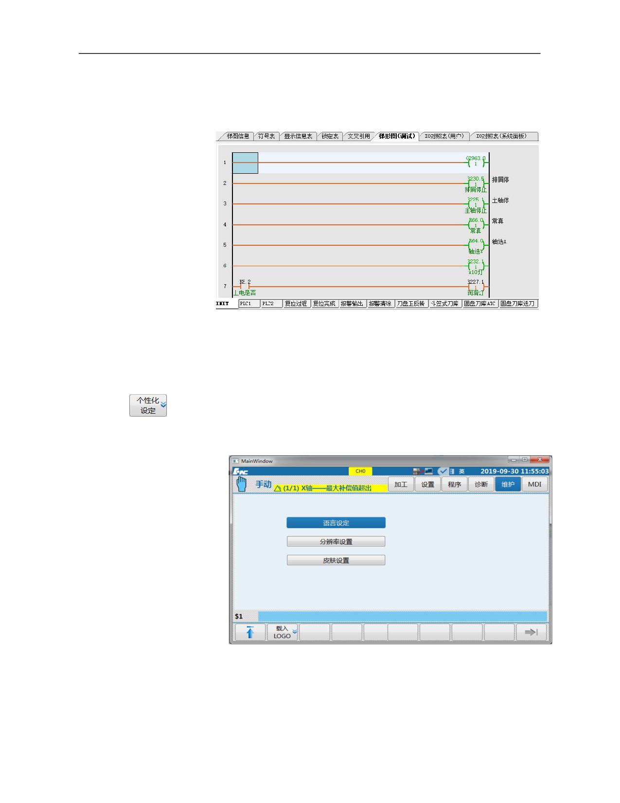
(6) Click on "Start program monitoring" under the diagnosis menu, and the PLC
commissioning software will load system PLC automatically, as shown below.
3.6.8.6 Personalized setup
The system version can be realized through personalized setup: Language
setup, resolution setup and skin setup. Press 『Personalized setup』 soft key
under "Maintain" function set to enter the personalized setup sub-interface, as
shown below. The modification should be validated after restart.
1. Language setup
Language setup can modify system interface language among Chinese,
English and Russian.
97
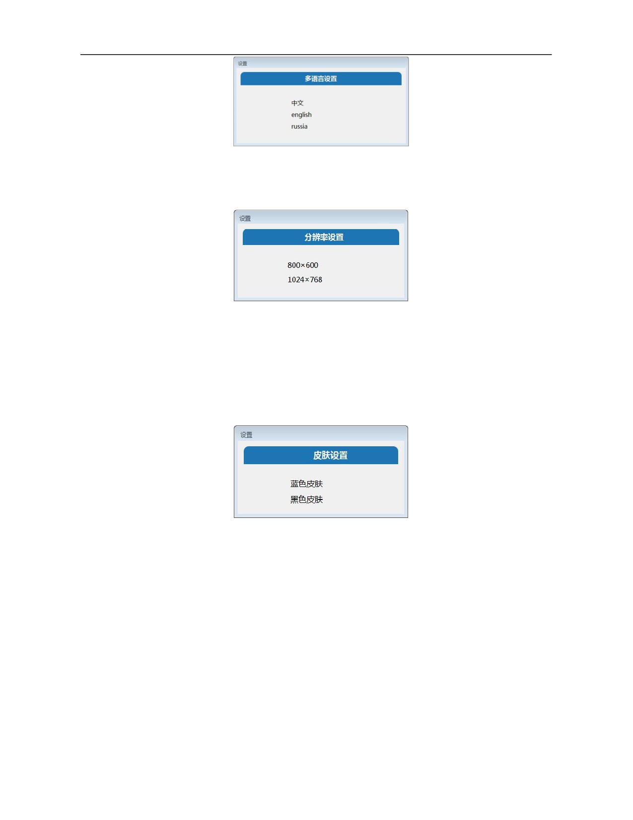
2. Resolution setup
Resolution setup can modify resolution as 800*600 or 1024*768
Note: If BIOS is set as 1024*768, the system supports two resolutions. If
BIOS is set as 800*600, the software supports 800*600 only (BIOS is set as
1024*768 by default).
3. Skin setup
The skin both in black and blue are supported. Subsequent versions will
support gray as well.
3.6.9 Process Package Setup
This function is used to back up process-related optimal parameters, record
them in XML file, and export them to other machine tools.
Press 『Process package』 soft key under the "Maintain" function set to enter
the "Process package" sub-interface, as shown below.
98
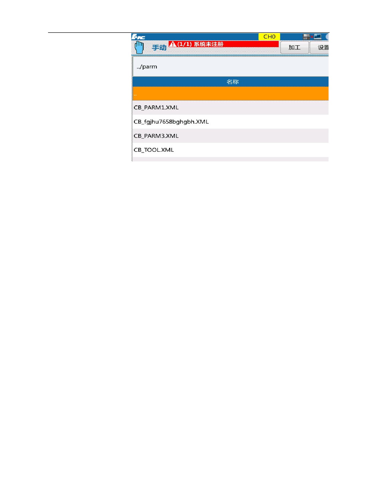
"Process package" of this system is shown below:
Backup
Users can select an XML file and click on Backup to back up the
parameter values corresponding to no (parameter id) in the XML file
into XML file.
Load
Users can select an XML file and click on Load to load the values in
val in the XML file into the parameters corresponding to no of the
system.
Rename
Users can select an XML file and click on Rename, and the system
will prefix the file name with “CB_”. If “.XML” is not added, the
system will suffix the file with “.XML” automatically
Copy, paste
Users can copy, paste and delete XML file among different disks
(except the network disk).
Note:
The directory of process package is parm, and process file can be
renamed.
Naming rule for XML file: CB_*.XML. “CB” and “XML” is in
capital form. The format is shown below:
99
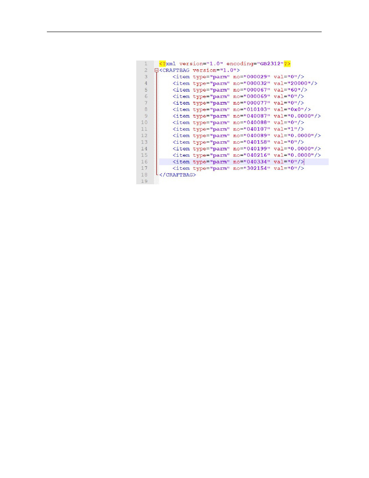
version is 1.0;
encoding is GB2312;
Start with “CRAFTBAG” in capital form, and attribute version is
1.0;
- type is the type, it is in lowercase “parm” if it is a parameter;
no is the parameter number;
val is the parameter value;
100