HNC-8 System Operating. Manual (Milling Machine) V2.4 Series - page 2
3 Display Interface
3.1 Display Interface Selection and Menu Structure
3.1.1
Common Operation of Interface and Menu Selection
1)
There are 6 function keys on the NC panel, which can be used to
select corresponding function sets and display interfaces.
2)
There is a group of function menus in the lower part of display
interface, and the function menu is selected by soft key.
3)
Each group of function menus consists of 10 soft keys (space key is
often reserved), among which the leftmost key is "Return to the
previous menu key" (『↑』), the rightmost key is "Continue menu key"
(『→』) , and the arrow is valid when it is in blue.
4)
The interface displayed when function key is selected for the first time
after startup is the default interface of the function set. The function
menu below is the level 1 main menu. The extension menu of this
level can be found by 『→』.
5)
Menus of all levels under function set has at most 1 main menu and 1
extension menu. Press 『→』 for cyclic switching. At this time, only
menu changes, interface does not change.
6)
The interface selection before function set is switched will be
memorized. That is, while switching back to this function set, the
displayed function menu and the interface are the menu and interface
upon the previous exit.
7)
Function sets of this system are at most a 4-level menu structure, and
the function soft keys marked with "︾" on the right can be used to
find lower-level menus. To return to the previous menu, use the "↑"
key.
8)
For configuration of soft keys of menus at all levels, the standard
version of this system has set personalized display interface or menu
according to actual needs. For special needs, users can also configure
by themselves.
9)
Generally data input and other man-machine dialog boxes can be
opened using corresponding soft keys, but for some data input with
high safety requirements, activate the input box using "Enter"
(「Enter」) and then input data or parameters.
10)
When the man-machine dialog box does not exit, function sets cannot
26
be switched by function keys.
11) Exit mode of man-machine dialog box:
Correctly input data and press "Enter" (「Enter」). After data
is correctly entered, exit the dialog box.
If current input is activated improperly or abandoned, press
"Reset" (「Reset」) to exit the dialog box, and the input data
will not be recorded.
3.1.2 Function Menu Structure
The menu tree is the basic structure diagram of the standard version of the system. The increase, decrease, sorting
or position of the function menu will vary depending on the user's permission, parameter settings and the machine
tool manufacturer. For details, refer to the specification provided by the machine tool manufacturer.
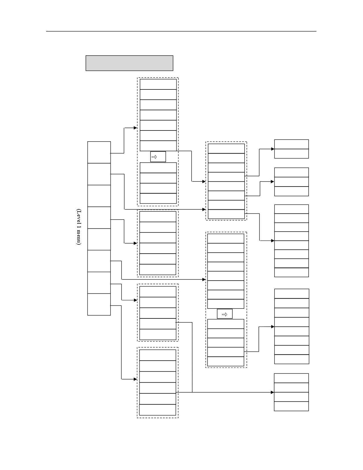
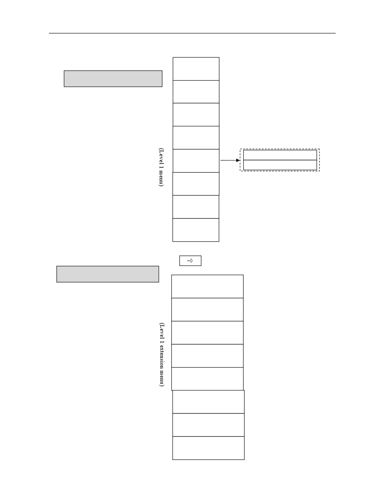
1) Level 1 menu of function sets
27
Machining
(Level 1 menu)
(Level 1 extension menu)
Select
Edit
Verify
Any
Display
Path
Tool
Coordinate
Machining
Macro
Ladder
Process
Machining
QR
Jog
program
program
line
switch
setting
compensati
system
informatio
variable
File
statistics
code
M S
on
n
Setting
(Level 1 menu)
Tool
Magazine
Tool
Coordinate
Workpiece
Auto
compensation
Life
system
measurement
tool setting
Program
(Level 1 menu)
(Level 1 extension menu)
System
USB flash
Network
New
Find
Copy
Paste
Delete
Set
Rename
Name
Time
New
Writable
read only
User
disk
disk
disk
program
mark
sort
sort
directory
disk
Diagnosis
(Level 1 menu)
Alarm
Alarm
Ladder
Status
Axis
Macro
Servo
Log
informatio
history
display
monitorin
variable
adjustmen
n
g
t
Maintain
(Level 1 menu)
(Level 1 extension menu)
Device
Parameter
Parameter
User
Batch
Data
System
Permission
Spatial
Time
Process
Machine
System
Register
configurati
set
classificatio
Set
manage
upgrade
manage
compensati
Set
Package
Information
information
on
n
on
MDI
(Level 1 menu)
Dwell
Clear
Save
Enter
28
2) Menu structure of "Machining" function set
(1) "Machining" main menu
"Machining" main menu
System disk
USB flash disk
User disk
Network disk
Find
Canned cycle
Select
Backstage edit
Find
New
program
Find next
Save
Edit
Machining
Save as
program
optimization
Replace
Cancel optimization
Find
Replace next
Sort by name
Find next
Verify
Replace all
Replace
Sort by time
Position line
Block head
Any
Block
line
Designated
line
Block end
number
Designate N lines
Clear
Display
Search
Copy
switch
View switch
Cut
Continue search
Graphic restore
Path
Paste
Window switch
Move up
set
File head
Move down
Input
File end
Tool
Move left
compensati
on
Move right
Current position
Zoom in
G54
Coordinate
system
Incremental input
G55
Zoom out
Relative actual
G56
Relative clear
G57
View switch
G58
Clear all
Graphic restore
G59
Color configure
G54.1P
Graphic center
Current input
G92
Graphics set
Incremental input
G54~G59
All axes
G54.1P
X
Relative clear
Y
Z
Clear all
29
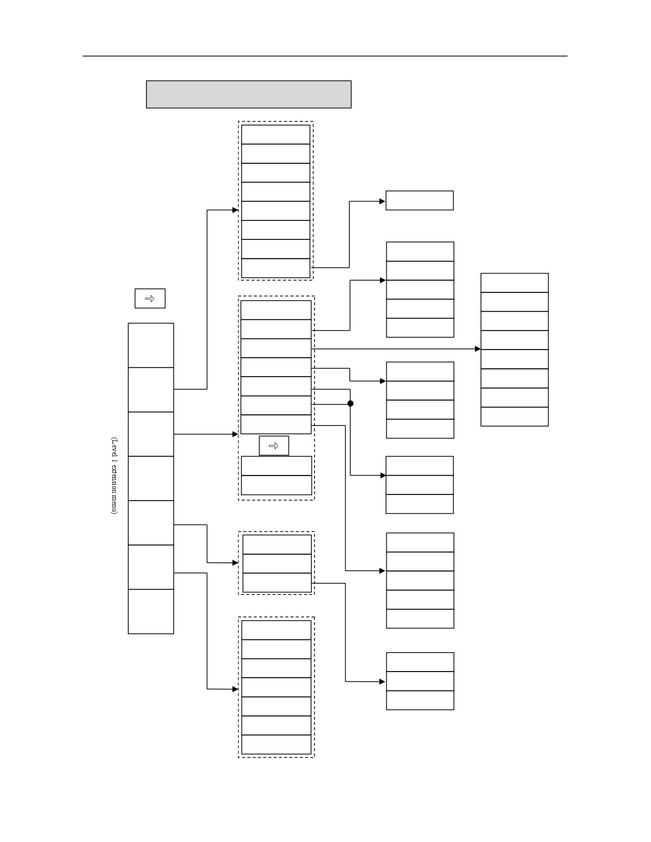
(2) "Machining" extension menu
"Machining" extension menu
All
Local variable
Channel variable
System variable
Find
Axis variable
Tool variable
Find
Add
User macro
Delete
User IO
Find
Panel IO
Ladder title
Update modification
Add
Symbol table
Undo modification
Machining
information
Delete
IO comparison table
Find
K parameter
Set valid
Macro
Find next
variable
Timer
ON
Update modification
Counter
OFF
Undo modification
Ladder
Alarm set
information
Find
Process
Stop operation
Find
file
Online debug
Update modification
Undo modification
Machining
statistics
Preset
Alarm
QR
code
Clear
Prompt
Operation statistics
Find
Jog
Update modification
M S
Undo modification
Machine status
Workpiece statistics
Clear single
Alarm history
Clear all
Fault diagnosis
Export
Commissioning
report
APP download
Health security
30
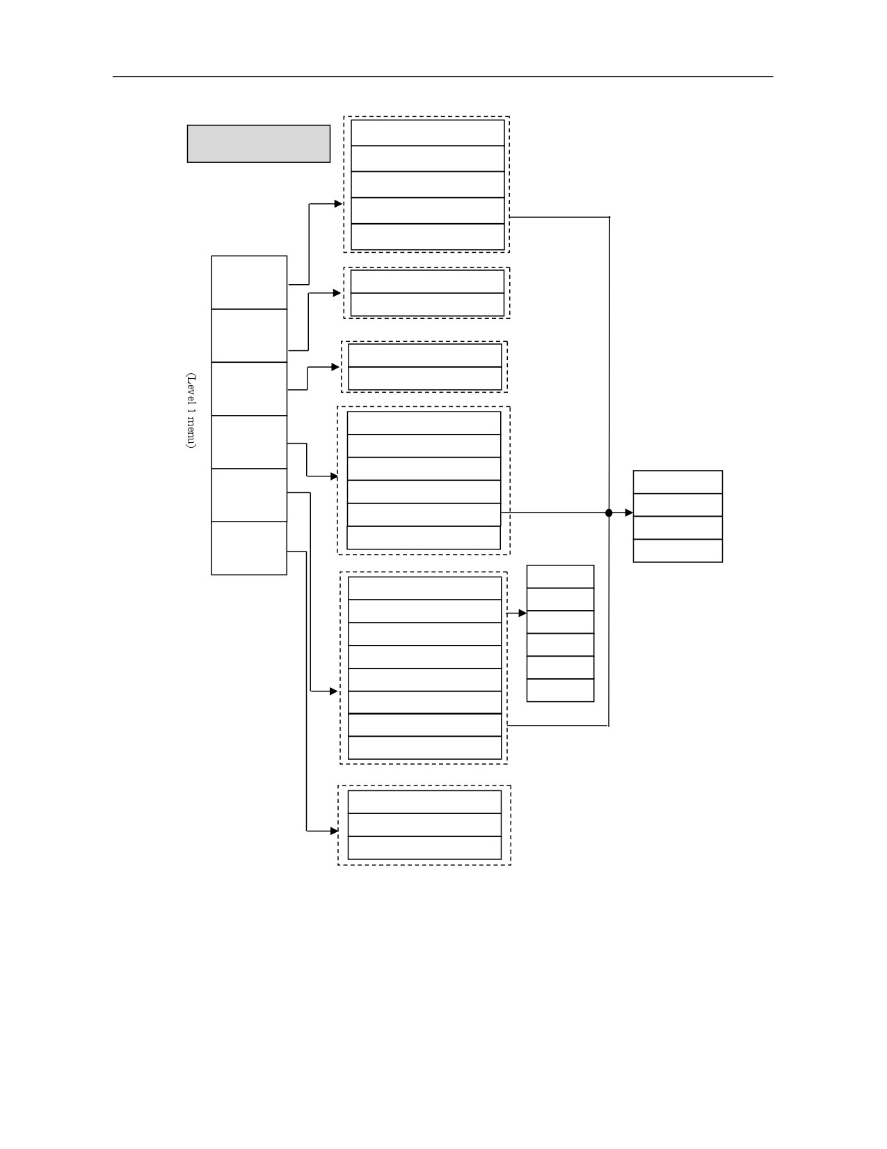
3) Menu structure of "Setup" function set
Current position
"Setup" menu
Incremental input
Relative actual
Relative clear
Clear all
Tool
compensation
Magazine
Magazine configure
Magazine
Find tool number
Tool
Alarm strategy
life
Coordinate
Current input
system
Incremental input
G54~G59
Workpiece
All axes
measure
G54.1P
X
Relative clear
Y
Auto
Clear all
tool setting
Z
G54
Coordinate set
G55
G54-G59
G56
G54.1P
G57
Read
G58
Center measure
G59
Plane measure
Relative clear
Circle center measure
Start
Drop setting
Current position
31
4) Menu structure of "Program" function set
System disk
"Program" main menu
USB flash
disk
Network disk
New program
Find
Find
Find next
Copy
Paste
Delete
"Program" extension menu
Set mark
Rename
Name sort
Time sort
New directory
Writable
Read only
User disk
32
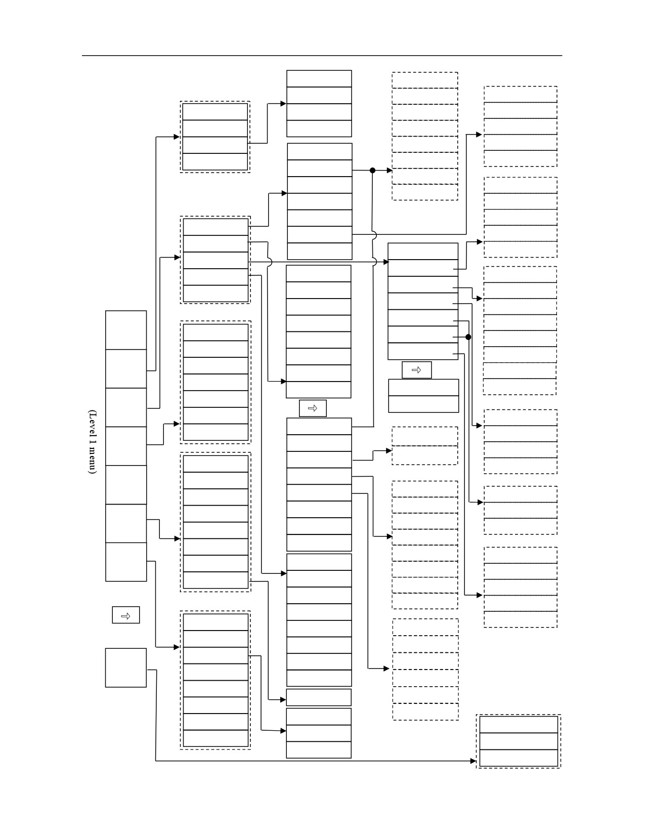
5) Menu structure of "Diagnosis" function set
System disk
Find addres
USB flash disk
Find command
Add
Alarm history
User disk
Find output
Delete
Status record
History export
Find line number
Write
Alarm manage
Find up
Lock
Program list
Empty history
Find down
Unlock
Find
Find mode
Inhibit
Add
Find range
Allow
Delete
Recover
Find
Ladder monitor
Lock list
Update modification
Ladder edit
Cross reference
Ladder title
Undo modification
Ladder information
Symbol table
Program list
User IO
Signal track
IO comparison table
Straight line
Panel IO
Ladder option
K parameter
Normally open
Add
Alarm
Timer
Normally closed
Delete
information
XYR
Counter
Logic output
Find
FG
Alarm set
Inverse output
Find next
Alarm
history
B
Vertical line
Update modification
IQ
Stop operation
Undo modification
Delete vertical line
Ladder
W
Online debug
D
Valid set
Find
Find
ON
Status
Function command
display
Delete element
table
H
OFF
elp
Function module
All
Find
Axis
Edit network
Local variable
monitor
Insert line
List editing
Find
Channel variable
Delete line
Double coil
Update modification
Macro
System variable
variable
Insert column
Update modification
Undo modification
Axis variable
Select network
Undo modification
Tool variable
Servo
Copy network
Alarm
Adjustment
Start
Find
Cut network
Prompt
User macro
Stop
Paste network
Find
Mark
Delete network
Update modification
Zoom out
Start sampling
Undo modification
Zoom in
Modify list
Stop sampling
Move up
Modify comment
Configuration
Log
Move down
Add module
Export
Parameter
Delete module
Restore
Modify module
Find
Operation
Undo modification
Configuration
Application
Clear all
Code preview
Save
Find
Color configuration
Time sort
33
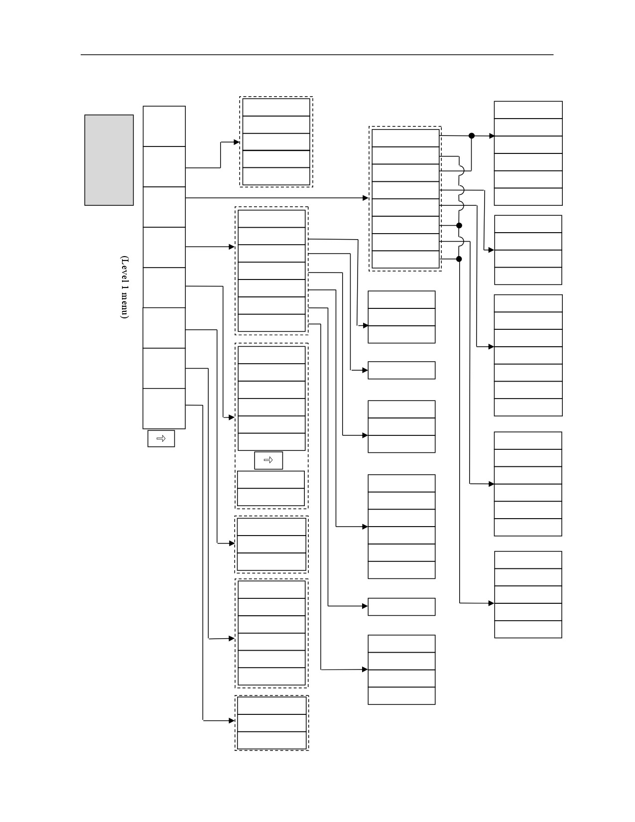
6) Menu structure of "Maintain" function set
(1) Level 1 main menu of "Maintain"
Save
Save
Device
Configuration
Input password
Input password
"Maint
User parameter
Default
ain"
Find
Parameter
Machine
tool
Find
main
Set
parameter
Find next
Axis parameter
menu
Auto offset
Default
Pitch compensation
Parameter
Auto offset
Classification
IO device
Display set
Local spindle device
Compensation
information
User
P parameter
Bus axis device
Load rtl
Set
M code
Machining parameter
Save
PLC switch
Batch
One-click clear
Communication
Find
Personalized setting
Save
Data
Update modification
Closed-loop switch
Input password
Manage
Undo modification
Find
System
USB flash disk
Find next
Upgrade
User disk
Find
Default
Load
IO device
Permission
Manage
Backup
MCP device
Valid set
Delete
ON
Window switch
Save
OFF
Input password
Find
Parameter restore
Local
Find next
PLC restore
Shared disk
Default
FTP
Data type
Bus axis device
Network connection
USB flash disk
Network
User disk
disconnection
Save
PING
Input password
USB flash disk
Find
User disk
Load logo
Find next
Copy
Default
Paste
Closed-loop switch
Delete
Closed-loop
parameter
Window switch
Load
Backup
Change password
Logout
Permission configure
34
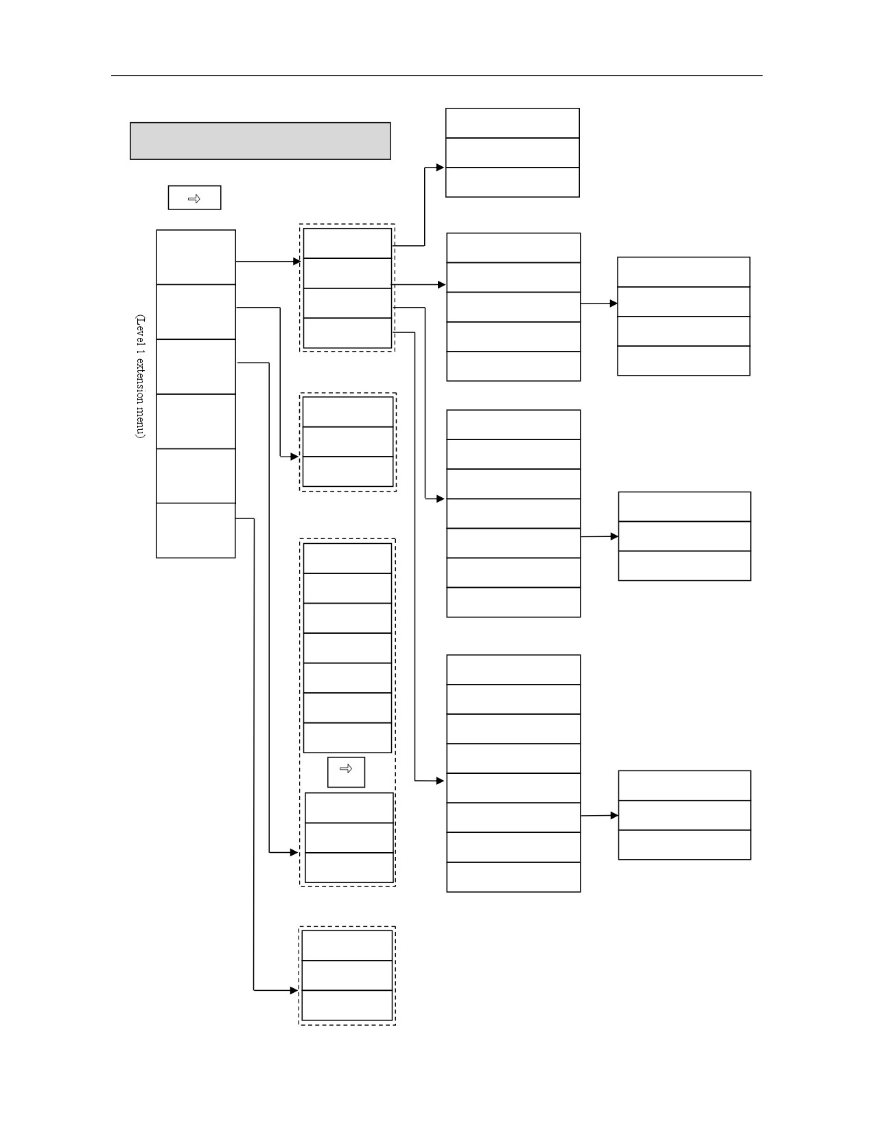
(2) Level 1 extension menu of "Maintain"
USB flash disk
"Maintain" extension menu
Set mark
Read
Spatial
Read file
All
compensation
Linearity
Backlash
Bidirectional
Time set
Straightness
Unidirectional pitch
Forward
Angle
Bidirectional pitch
Reverse
Process
clear
Load
package
Machine
Time edit
information
All
Time sett
Bidirectional
System
Cancel set
information
Forward
Unidirectional straight line
Reverse
Register
Bidirectional straight line
Horizontal
System disk
Clear
Vertical
USB flash disk
Load
User disk
Network disk
All
Backup
Bidirectional
Load
Forward
Rename
Reverse
Deflection
Unidirectional angle
Copy
Pitching
Bidirectional angle
Paste
Roll
Clear
Delete
Load
USB flash disk
CF card
Renewal
35
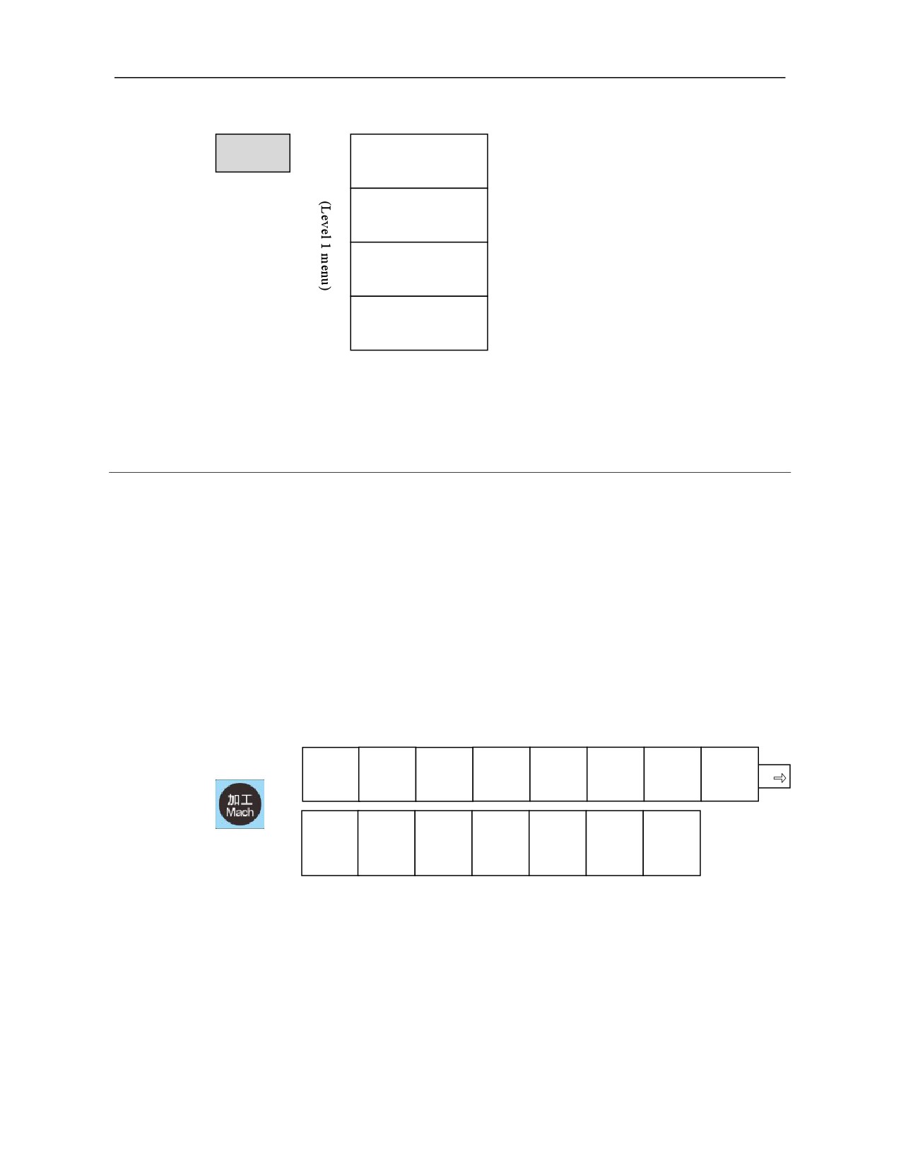
7) Menu structure of "User-defined (MDI)" function set
MDI
Dwell
Clear
Save
Input
3.2 Display Interface and Basic Operation of "Machining" Function
Set
3.2.1
Interface and Function of "Machining" Function Set
"Machining" function set integrates all functions required for parts machining and is
compatible with some functions of function set "Setup", "Program" and "Diagnosis",
which greatly reduces interface switching. The operations that can be conducted
under the function set include select machining program, select editing program,
edit new program, verify program, tool setting (coordinate setup, tool compensation
setup), any line, parameter configuration, coordinate display, graphic display,
machining information display and user macro query, etx. Level 1 main menu and
level 1 extension menu of "Machining" function set are shown below.
Select
Edit
Verify
Any line
Display
Path set
Tool
Coordinat
program
program
switch
compensa
e system
tion
Machinin
Macro
Ladder
Process
Machinin
QR code
Manual
g
variable
informati
file
g
M S
informati
on
statistics
on
Select program: Select a program from the target disk (system disk, USB flash
disk, user disk and network disk) and load it as the machining program; or select a
program and edit it through backstage editing; and edit a newly created program.
Edit program: Edit the loaded program, namely the current machining program.
A running program cannot be edited.
Verify: Enable this function under "Auto" or "Single block" working mode to
quickly verify current loading program, and detect alarms of programming and
grammar during program running.
36
Any line: Designate programs to run from any line under "Auto" working
mode. Specific operations of this function are introduced in 7.2.3 of this manual.
Display switching: Cyclic switching display: Big character coordinate + program,
joint coordinate, graph+ program, program.
Path setup: Used to set view switching, graphic restoration, path color, graphic
center, graphic scaling setup of the programmed path.
Tool compensation: Compensation values such as tool length, length wear, radius
and radius wear can be set under the sub-interface of this function. Jog tool
compensation input mode and automatic measurement input mode are introduced
in detail in Chapter 8 of this manual.
Function and operation of "Tool compensation" under "Setup" function set are the
same as those of "Tool compensation" under "Machining" function set.
Coordinate system: This function can be used to set values of the workpiece
coordinate system through direct input, current value input and incremental input
mode.
Function and operation of "Coordinate system" under "Machining" function set
are the same as those of "Coordinate system" under "Setup" function set.
Machining information: Cyclic switching display: Contents of "Machining
information" and "G command modal"
Macro variable: Local variable, channel variable, system variable, axis variable,
tool variable and user macro variable of the system can be displayed and queried.
Ladder information: Query and modify title information, symbol table, IO
comparison table, K parameter, timer, counter and alarm setup in the ladder
diagram.
Process file: Store and view process card of machining program.
Perform statistics on the workpiece required, completed quantity, and accumulated
quantities, as well as the current running, cumulative running, and current
cutting time.
QR code: Generate QR code of machine tool status, workpiece statistics, alarm
history, fault diagnosis, commissioning report, APP download and health security
information for scanning and viewing using mobile APP.
Manual MS:
When there is no command F (sub-feed)/S (spindle speed), set it
using this function, and save it as system modal amount. If it has been set in the
program, use the set value as the modal amount.
3.2.1.1 Machining set interface zoning
After startup, press
〖Machining〗 function key to enter the default interface of
37
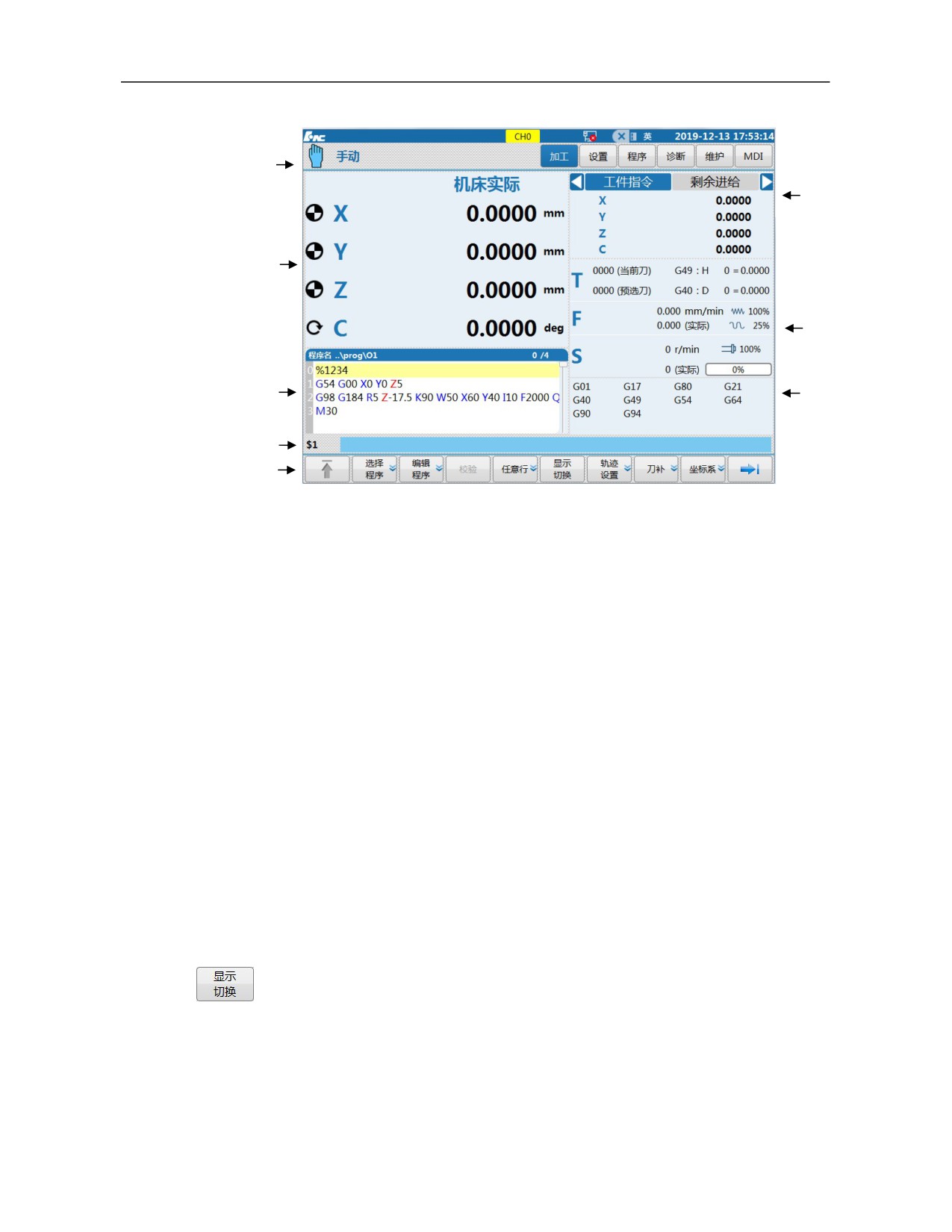
"Machining" function set, as shown below.
(1)
(6)
(2)
(7)
(3)
(8)
(4)
(5)
(1)
Area--Machining mode, alarm message, prompt message and main function set
display area
(2)
Area--Coordinates and graphics display window: Coordinate and graphics path
display area.
(3)
Area---G code display area: Preview or display code of machining program.
(4)
Area---Input box: Enter information to be inputted in this column.
(5)
Area---Menu command bar: Operate system functions through function keys in the
menu command bar.
(6)
Area---Axis status display area: Display coordinate position, pulse value, breakpoint
position, compensation value and load current of axis.
(7)
Area---Auxiliary function: T/F/S information area.
(8)
Area--Machining information area: Display G modal, program progress and
workpiece statistics during machining.
3.2.1.2
Switching of graphics and G code area display
For switching of graphics and G code areas (2) and (3) display , press
『Display switch』 soft key under the main menu interface of this function
set, and the display interface switches among 4 interfaces: big character
coordinate+ program, joint coordinate, graphics + program and program.
(Detailed in 1.3.1)
38
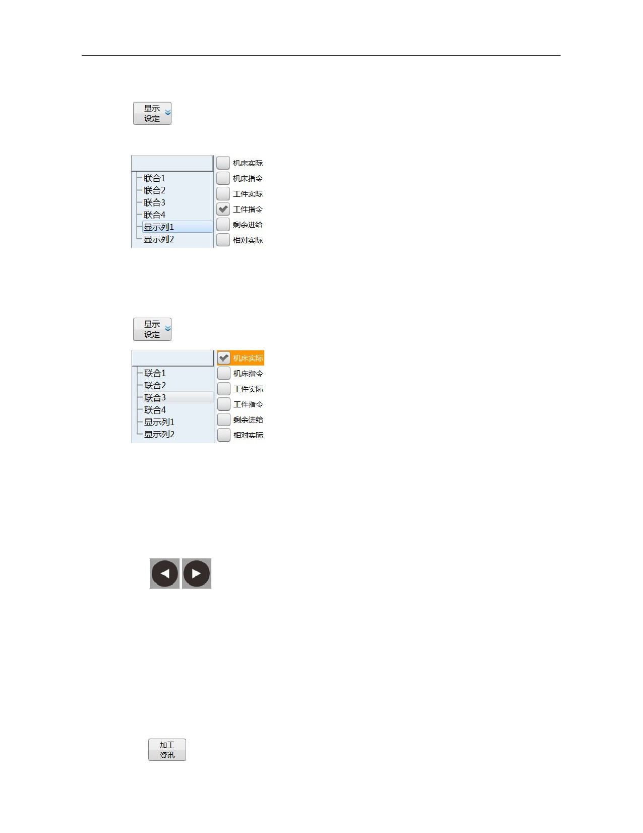
3.2.1.3 "Big character coordinate" display setup of coordinate graphics display
area
For big character display setup of coordinates and graphics
display area
(2), press
『User setup』 soft key under the
"Maintain" function set interface to enter the lower-level menu,
press 『Display setup』 soft key to enter the lower-level menu,
select "Display column 1" and "Display column 2", and set big
character coordinate content in the "Big character coordinate+
program" interface (for details, refer to "User setup" in 3.6.8).
3.2.1.4 "Joint coordinate" display setup of coordinate graphics display area
For joint coordinate display setup of coordinates and graphics
display area
(2), press
『User setup』 soft key under the
"Maintain" function set interface to enter the lower-level menu ,
press『Display setup』 soft key to enter the lower-level menu,
select "Joint 1-4", and set 4 coordinate contents in the "Joint
coordinate" interface
(for details, refer to "User setup" in
3.6.8) .
3.2.1.5 Switch of machining and commissioning information area display
For display switching of machining and commissioning information area (6) ,
press 「Alt」+「Left and right cursors」 on the MDI keyboard to display the
following items and values successively: Machine actual, machine command,
workpiece actual, workpiece command, remaining feed, relative actual,
relative command, breakpoint position, tracking error, workpiece zero, zero
offset, compensation value, actual coordinate
2, synchronous error,
handwheel offset, Z pulse offset, Z pulse interval 1, Z pulse interval 2, actual
speed, motor position, command pulse, actual pulse, motor speed, waveform
frequency, load current and temperature.
3.2.1.6 Switching of machining information area display
For display switching of machining information area (8), press 『Machining
information』 soft key under the "Machining" function extension menu
interface to switch G modal, machining quantity and other information.
39
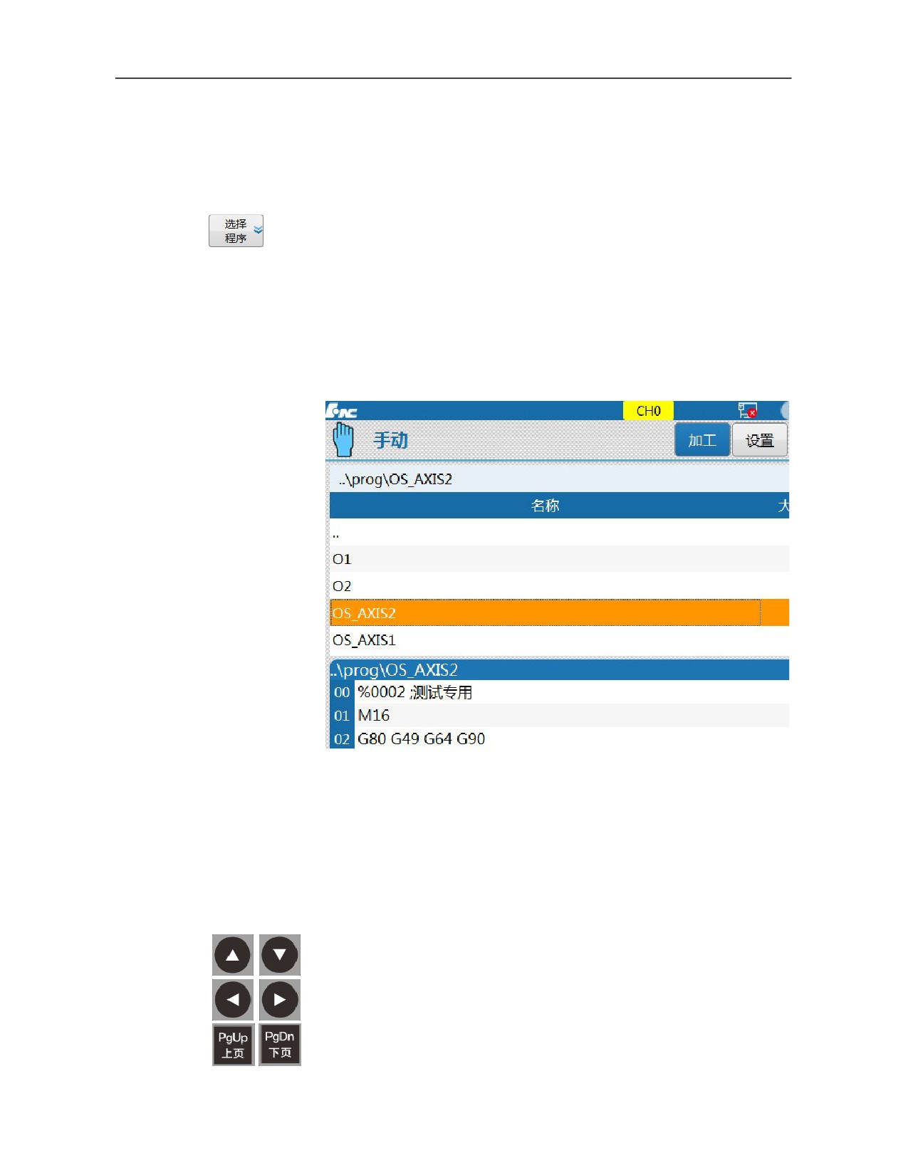
3.2.2 "Select Program" Sub-Interface
Main function of "Select program" sub-interface includes: select
machining program, select editing program, edit program, and create new
programs. The existing programs in system disk, USB flash disk and
network disk can be selected.
Editing program and creating new programs are realized by "Backstage
editing" in the lower-level menu, and the machine tool should not be at
running status while editing current machining program.
Press
〖 Machining 〗 function key to enter the level
1 menu of
"Machining" function set and press 『Select program』 soft key to enter
the interface, as shown below.
3.2.2.1 Select a program in the USB flash disk and load it as current machining
program
Press 『 Select program 』 to enter the "Select program"
sub-interface;
Select soft keys of program source disk, namely soft keys of
『System disk』, 『USB flash disk』『User disk』 and 『Network
disk』, and enter the corresponding program source disks;
Press 「Cursor」 or 「PgUp/PgDn」 to select program file to
40
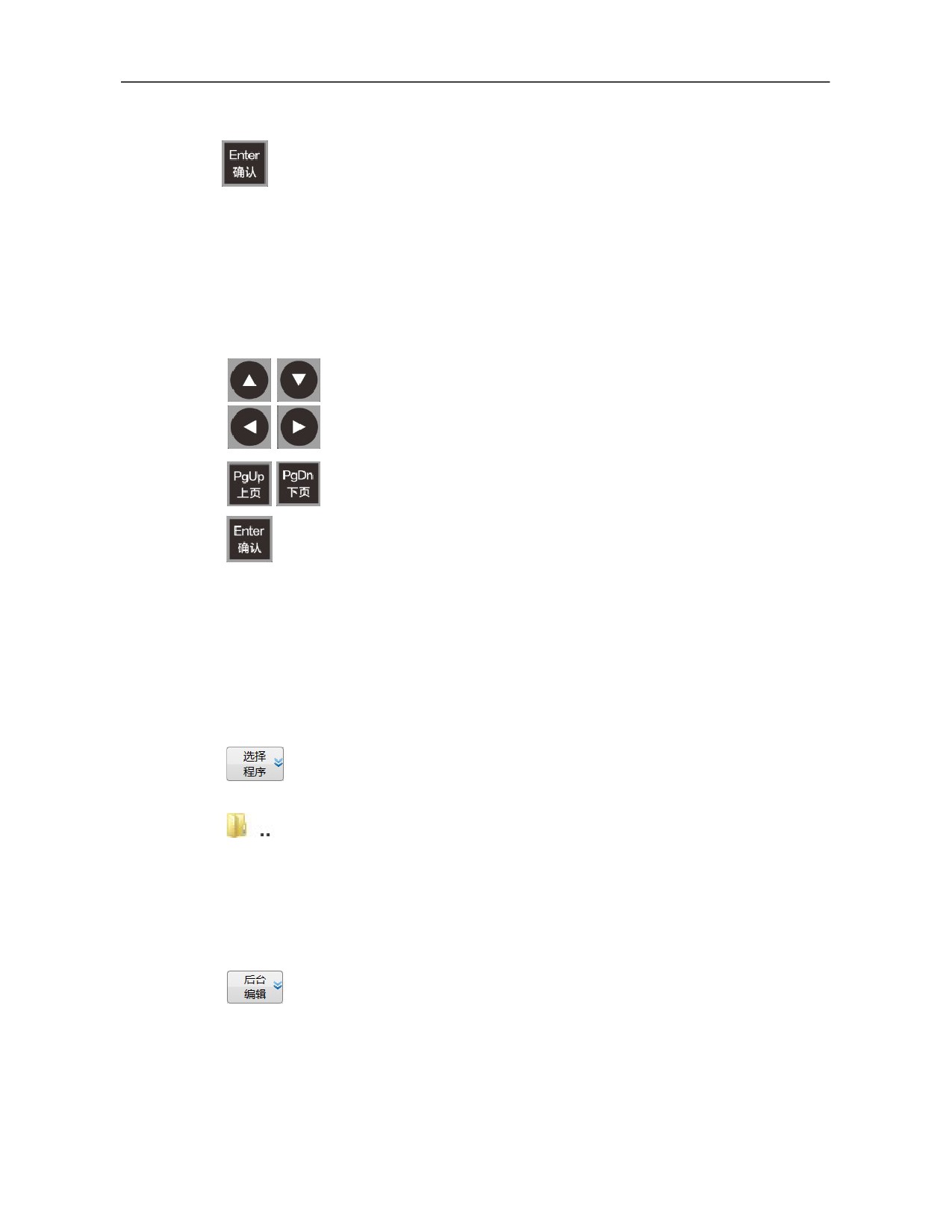
preview program;
Press 「Enter」 to load the selected program as the current
machining program, and revert to the previous menu and
interface. After that, parts can be processed.
Note: If an error is reported while loading a program, press 「Reset」 to
clear it and press
『↑』 to return to level 1 interface);
3.2.2.2
Select a program in the directory as current machining program
Press 『 Select program 』 to enter the "Select program"
sub-interface;
Select soft keys of program source disk, namely soft keys of
『System disk』, 『USB flash disk』『User disk』 and 『Network
disk』, and enter the corresponding program source disks;
Press 「Cursor」 or 「PgUp/PgDn」 to select the file directory;
Press 「Enter」 to activate the selected directory, enter the
directory and display program files underneath.
Press 「Cursor」 or 「PgUp/PgDn」 to move the cursor to the
program file name;
Press「Enter」to load the selected program as current machining
program, and revert to the previous menu and interface. After that,
parts can be processed.
3.2.2.3
Exit file directory
When the cursor is on a file name under the file directory, exit the
directory as below:
Press 「Cursor」 or 「PgUp/PgDn」 to move the cursor to the
directory item (back to the previous directory identifier.);
Press 「Enter」 to exit the current directory.
3.2.2.4
Edit current machining program in the backstage
Current machining program cannot be edited when the program runs,
but it can be edited using backstage edit function under non-running
status.
Press "Program select" soft key to enter the "Select program"
sub-interface;
Press 「Cursor」 or 「PgUp/PgDn」 to select file name of current
machining program;
41
Press 『Backstage edit』 soft key to enter the editing interface to
edit current machining program;
After editing or modification, press 『Save file』 soft key, and a
prompt message Saved will be given, then return to the previous
interface or other operations.
Before a file is saved, a prompt message "Save or not" will be
given. Press 「Y」 to save the file and 「N」 or 「Reset」 not
to save the file.
Note: When the program is not selected under "Select program"
sub-interface
(when the cursor is on the file directory), it is not
allowed to enter the "Backstage edit" sub-interface.
3.2.2.5
Edit other programs than current machining program in the backstage
Press "Program select" soft key to enter the "Select program"
sub-interface;
Select soft keys of program source disk, namely soft keys of
『System disk』, 『USB flash disk』『User disk』 and 『Network
disk』, and enter corresponding program source disks;
Press 「Cursor」 or 「PgUp/PgDn」 to move the cursor to the
selected program file to preview the program;
Press 『Backstage edit』 soft key to enter the editing interface to
edit the program;
After editing or modification, press 『Save file』 soft key and a
prompt message Saved will be given, then return to the previous
interface or other operations.
Before a file is saved, a prompt message "Save or not" will be
given. Press 「Y」 to save the file and 「N」 or 「Reset」 not
to save the file.
Note: When there is a program in the "Backstage edit" interface, the
loading status of current machining program is not affected
3.2.2.6
Edit and creates new programs in the backstage
Press "Program select" soft key to enter the "Select program"
sub-interface;
Select soft keys of program source disk, namely soft keys of
『System disk』, 『USB flash disk』『User disk』 and 『Network
disk』, and enter corresponding program source disks;
Press "Backstage edit" soft key to enter the "Backstage edit"
42
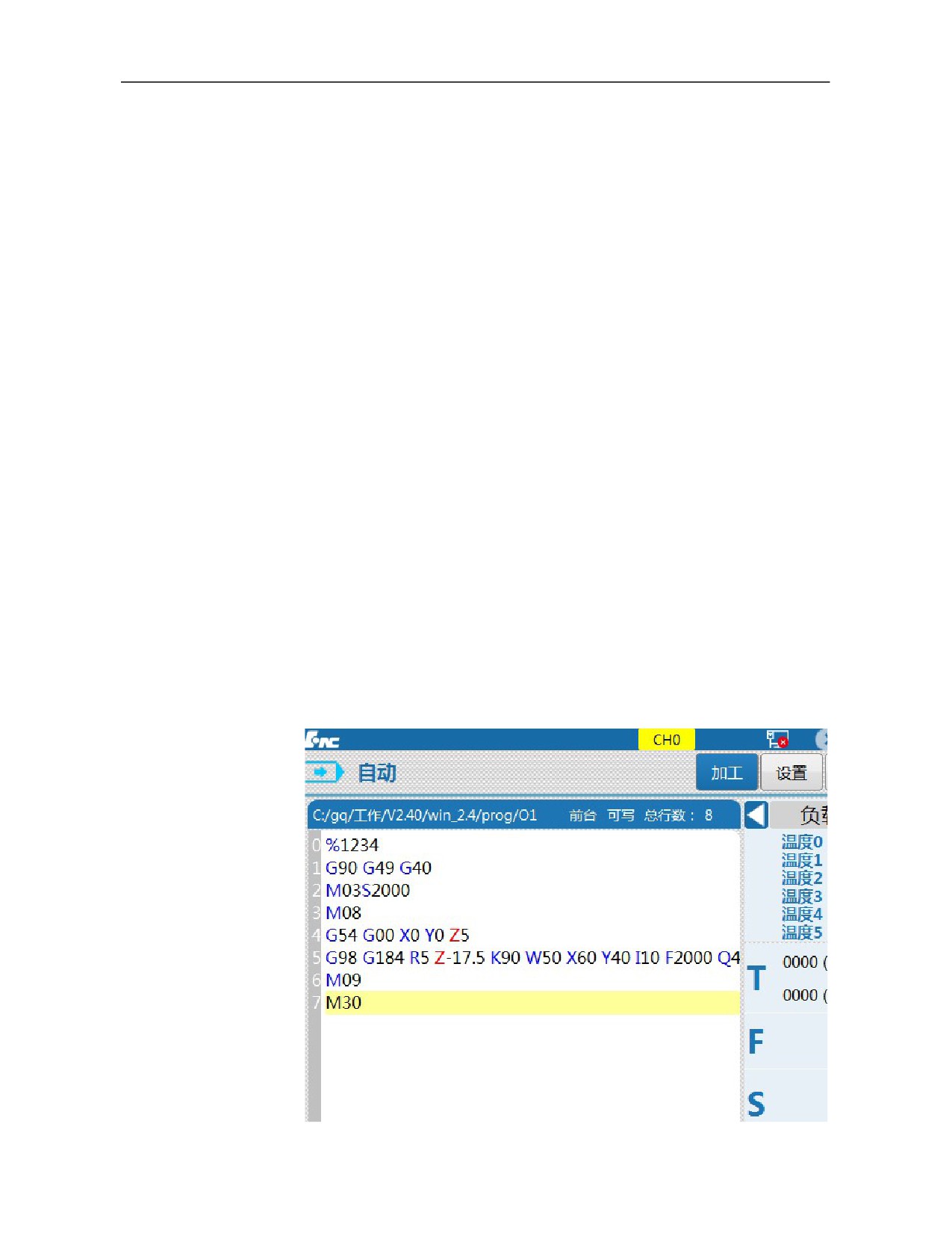
sub-interface;
Press 『New』 soft key and a prompt message "Please enter file
name: O temp" will be given in the input box; (press 「Reset」 to
exit the interface)
Enter a new program name (figure or letter) by MDI keyboard;
Press 「Enter」 to confirm the new file name to enter the program
editing area;
After editing or modification, press 『Save file』 soft key and a
prompt message Saved will be given, then return to the previous
interface or other operations.
Before a file is saved, a prompt message "Save or not" will be
given. Press 「Y」 to save the file and 「N」 or 「Reset」 not
to save the file.
Note: When a new program is created in the "Backstage editing"
interface, it will be loaded as the current machining program
automatically.
3.2.3 "Program Editing" Sub-interface
The "Edit program" sub-interface is mainly used to edit current machining
program and create and edit new programs.
Press 〖Machining〗 function key to enter the level 1 menu of "Machining"
function set and press 『Edit program』 soft key to enter the interface, as
shown below.
43
3.2.3.1
Edit current machining program
Press 『Edit program』 soft key under the "Machining" function
set and the cursor is in the editing area of current machining
program for editing the current machining program.
After editing or modification, press 『Save file』 soft key and a
prompt message Saved will be given, then return to the previous
interface or other operations;
Before a file is saved, a prompt message "Save or not" will be
given. Press 「Y」 to save the file and 「N」 or 「Reset」 not
to save the file.
Note: 1. The machine tool should not be at running status while editing
current machining program.
2. "Edit program" function cannot be used to edit other programs than
current machining program. Otherwise, other programs should be set as
the current machining program by "Select program" function.
3.2.3.2
Create new programs
Select "Edit program" soft key under "Machining" function set to
enter the "Edit program" sub-interface;
Select 『New』 soft key under the sub-interface and a prompt
message "Please enter file name: O temp" in the input box; (Press
「Reset」to exit the interface)
Enter a new program name (figure or letter) by MDI keyboard;
Press「Enter」to confirm the new file name to enter the program
editing area;
After editing or modification, press 『Save file』 soft key and a
prompt message Saved will be given, then return to the previous
interface or other operations.
Before a file is saved, a prompt message "Save or not" will be
given. Press 「Y」 to save the file and 「N」 or 「Reset」 not
to save the file.
Note: After a new program is saved under "Machining" function set, it
will be loaded as the current machining program automatically.
3.2.3.3
Block operation
"Block operation" function is often used for copy, paste multiple program
44
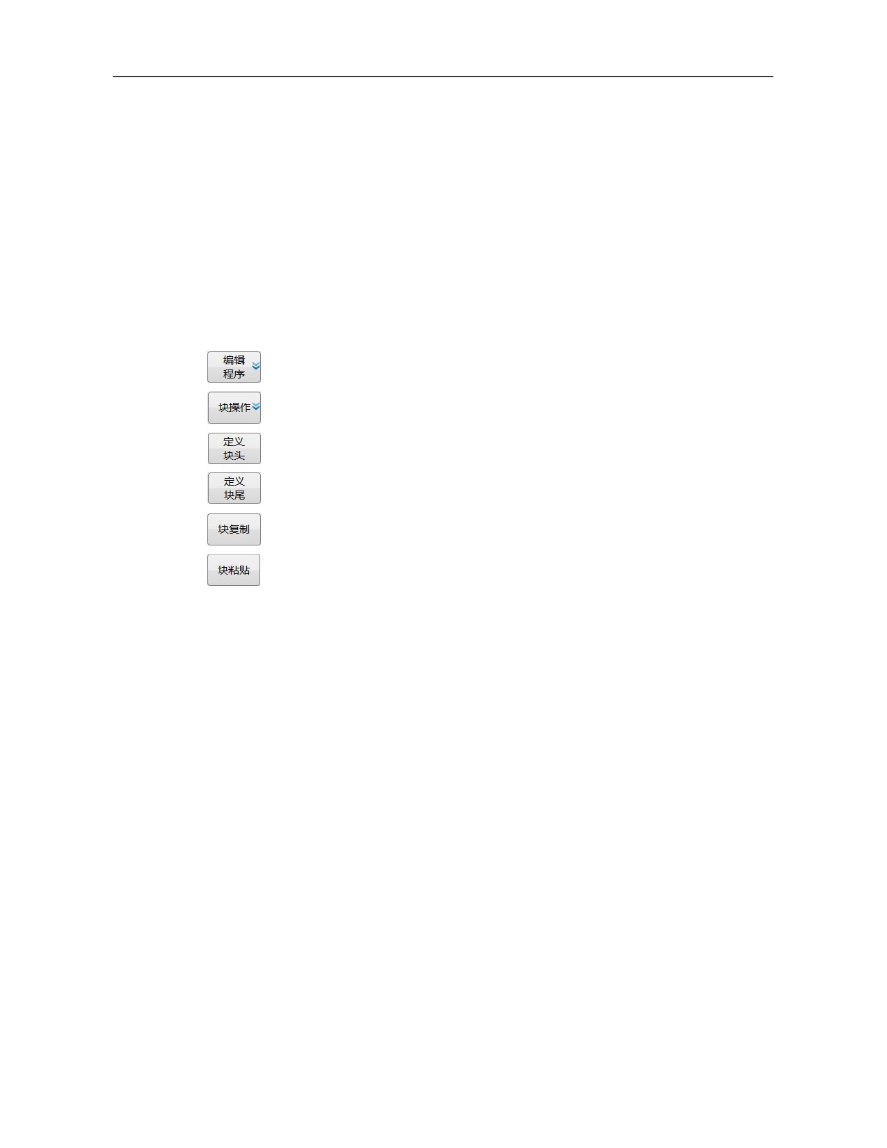
blocks. It defines the initial block and the final block of multiple program
blocks to define size and position of "block".
This function is easy for program editing, so this soft key is in the submenu
of program editing status. There are
4 program editing status: Under
"Machining" function set, edit and create program "Backstage edit" function;
under "Machining" function set, edit current machining program of "Program
edit" function; under "Program" function set, create program of "New"
function.
Block operation is described as below with copy and paste under the
"Program editing" sub-interface as an example
Press 『Edit program』 soft key to enter the sub-interface;
Press 『Block』 soft key to enter the block operation sub-interface;
Press Cursor or PgUp/PgDn to move the cursor to the first block of
the blocks to be edited;
Press 『Block head』 soft key
Press 「Cursor」or「PgUp/PgDn」to move the cursor to the final
block to be edited;
Press 『Block end』 soft key to select the big block program;
Press 『Copy』 soft key;
Press「Cursor」or「PgUp/PgDn」to move the cursor to the paste
position
Press 『Paste』 soft key to complete copy and paste.
3.2.4
"Verify" Sub-interface
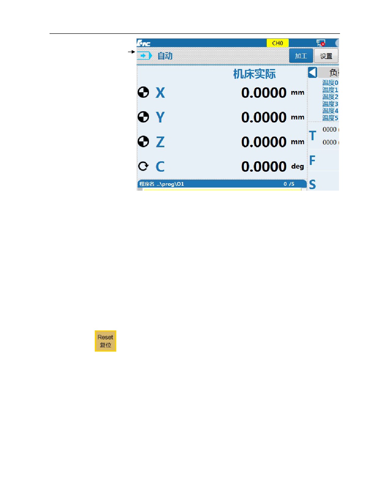
The "Verify" sub-interface is mainly used to quickly check programs, and at
this time the machine tool does not run.
Verifying program is valid under auto mode and single block mode. After
pressing 『Verify』 soft key, the working mode display changes from "Auto"
to "Verify".
Press 〖Machining〗 function key to enter the level 1 menu of "Machining"
function set, and press 『Verify』 soft key to enter the interface, as shown
below.
45
Working mode
3.2.4.1 "Verify" runs
Load programs under auto mode;
After pressing 『Verify』 soft key, the working mode changes to
"Verify";
Press [Cycle start] to verify programs.
(Feedrate override can
control the verification speed)
3.2.4.2 Exit "Verify"
After the program runs correctly, exit the verification status
automatically;
If verification is not conducted correctly or misoperation occurs,
press 「Reset」 to exit the verification status.
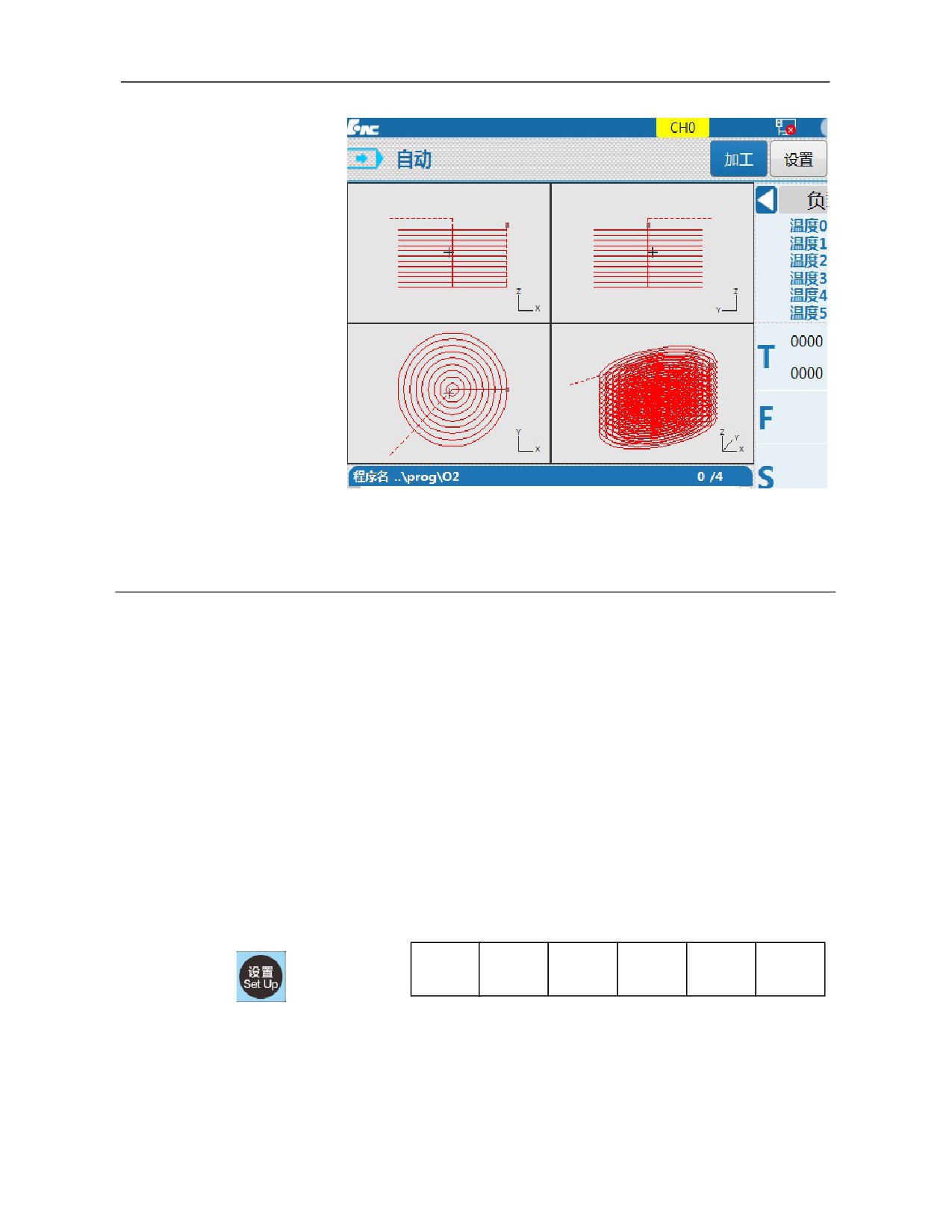
3.2.5 "Path setup" Sub-interface
Select program machining path display interface through cyclic switching of
"Display switch" soft key in the level 1 menu under machining function set.
View switching, graphic restoration, color configuration, graphic center and
graphic setup can be conducted in the interface.
Press 〖Machining〗 function key to enter the level 1 menu of "Machining"
function set and press 『→』 to enter the extension menu. Press 『Graphics
46
setup』 soft key to enter the interface, as shown below.
3.3 "Setup" Function Set Interface and Basic Operation
3.3.1
"Setup" Function Set Interface and Function
"Setup" function set integrates operation functions of tool setting. Operations
that can be conducted under the function set include tool setting operations
such as coordinate system setup, tool compensation setup *, automatic tool
measurement and workpiece measurement as well as tool life management.
This function set interface is recommended to be used as the main tool
setting operation interface. "Machining" function set interface should be used
as supplementary tool setting interface during machining (namely coordinate
and tool compensation value modification).
Level 1 main menu and level 1 extension menu of soft key function of
"Setup" function set are shown below.
Tool
Magazine
Tool
Coordinate
Workpiece
Auto tool
compensat
Life
system
measurem
setting
ion
ent
Tool compensation: Tool length compensation, radius compensation and
radius wear compensation values can be set under this function
sub-interface, and tool length compensation value can be set through
operations under 『Auto tool setting』 soft key.
Function and operation of "Tool compensation" under "Setup" function
47
set are the same as those of "Tool compensation" under "Machining"
function set.
Magazine: The magazine function interface displays tool number and
machining mode. The magazine tool configuration function interface
displays magazine type and magazine capacity.
Tool life:
This function can be used to set tool life management
strategy.
Coordinate system: This function can be used to set values of the
workpiece coordinate system through direct input, current value input
and increment input mode or save measured coordinate values through
operations under 『Workpiece measurement』 soft key.
Function and operation of "Coordinate system" under "Setup" function
set are the same as those of "Coordinate system" under "Machining"
function set.
Workpiece measurement: This function is used for center measurement,
plane measurement and circle center measurement of workpiece. The
measurement results are stored in G54-G59 and extension coordinate
system. For specific operating steps, please refer to "Tool setting and
machining setup'.
Auto tool setting: This function can be used for automatic tool length
measurement under the three applications including single tool single
workpiece, single tool multiple workpieces and multiple tools multiple
workpieces. The measured values are stored in the tool compensation
table. For specific operating steps, please refer to "Tool setting and
machining setup'.
Some functions of "Setup" function set are the same as those of "Machining"
function set. Functions introduced in "Machining" function set are not
introduced in this section.
After startup, press 〖Setup〗 function key to enter the default interface of
"Setup" function set, as shown below.
48
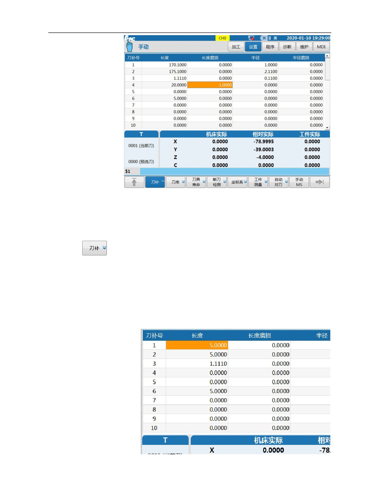
3.3.2 "Tool Compensation" Sub-interface
"Tool compensation" function is mainly used to set tool length compensation,
length wear, radius compensation, and radius wear.
Tool compensation value can be inputted manually, or automatically through
automatic tool measurement mode.
To simplify the operation, the system configures "Tool compensation"
function under "Machining" set and "Setup" set with the same function and
operation. This section is introduced with "Tool compensation" submenu
under "Setup" set.
49
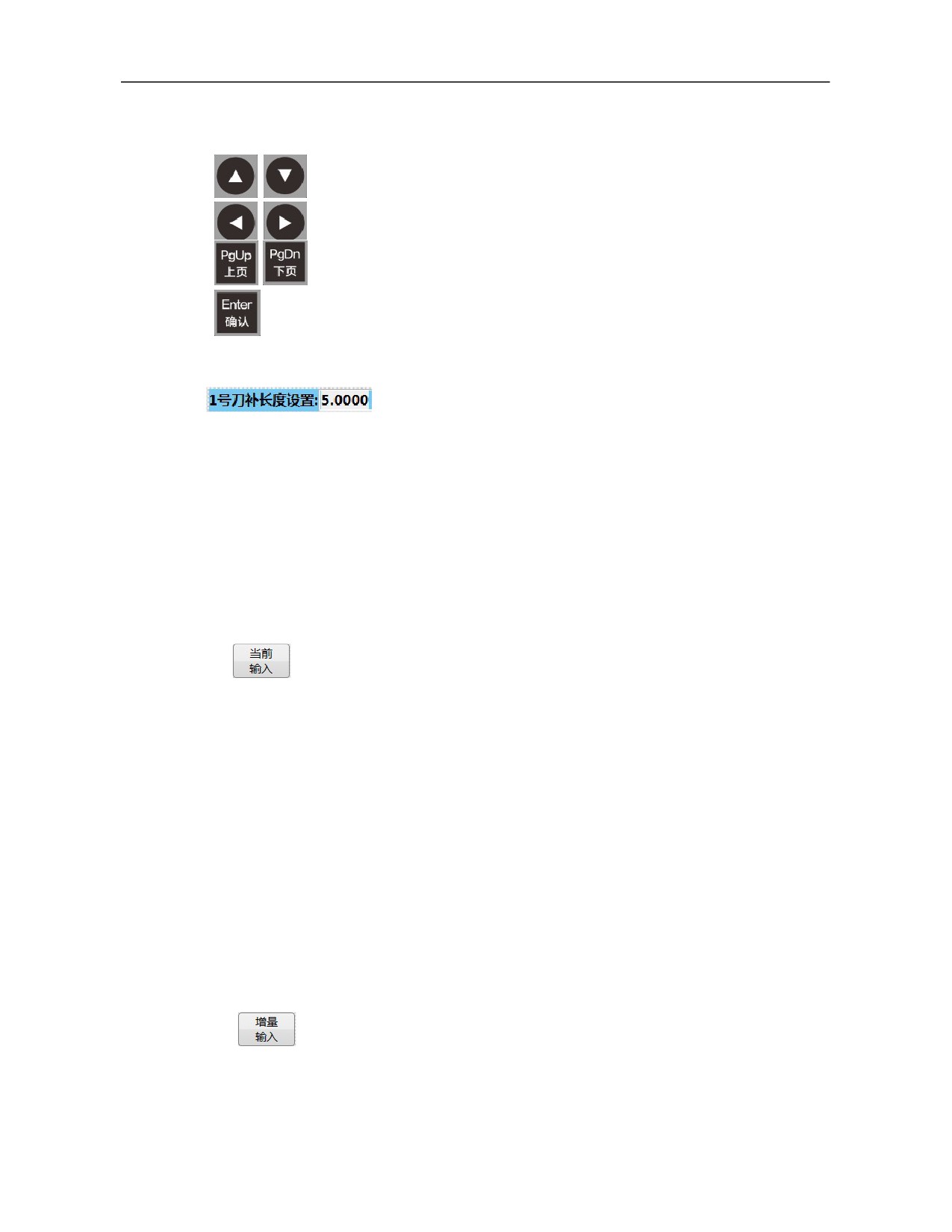
3.3.2.1 Direct input mode of tool length compensation
Press 『Tool compensation』 soft key in the level 1 menu of
machining function set to enter the sub-interface;
Press 「Direction」 or 「PgUp/PgDn」 to move the cursor to tool
length compensation of corresponding tool number;
Press 「Enter」 to confirm, activate input status, and the input box
gives a prompt message Input tool length compensation value of
the selected tool number.
Input correct figures using NC keyboard
Press 「Enter」 to confirm, the original tool compensation value is
replaced by the inputted value, the input box gives a prompt
message "Take effect from next tool changing or rerun", and exit
the input status.
3.3.2.2
Input mode of tool length compensation of current position
Input mode of tool length compensation of current position is to take
the actual machine coordinates when the tool nose touches the tool
setting face of the workpiece as the tool length compensation value.
Press 『Tool compensation』 soft key in the level 1 menu of
machining function set to enter the sub-interface;
Press 「Direction」 or 「PgUp/PgDn」 to move the cursor to tool
length compensation of corresponding tool number;
Under jog mode, move the tool nose to touch the tool setting face
of the workpiece, press
『 Current position 』 to write actual
machine position in tool length compensation value automatically.
3.3.2.3
Incremental input of tool length compensation
When there is tool length compensation value in the tool compensation
table, increase or decrease tool length compensation using increment
input mode.
Press 『Tool compensation』 soft key in the level 1 menu of
machining function set to enter the sub-interface;
Press 「Direction」 or 「PgUp/PgDn」 to move the cursor to tool
length compensation of corresponding tool number;
Press 『Incremental』 to activate the input box;
50